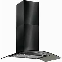
BT9.3BGL - Range hood BAUMATIC - Free user manual and instructions
Find the device manual for free BT9.3BGL BAUMATIC in PDF.


| Product Type | Range Hood |
| Brand | Baumatic |
| Model | BT9.3BGL |
| Width | 900 mm |
| Depth | 500 mm |
| Height (Adjustable) | 540 - 1010 mm |
| Chimney Section Dimensions | 260 x 350 mm |
| Extraction Capacity | 500 m³/h |
| Motor Type | High extraction tangential motor |
| Control Type | Electrical button control |
| Speed Settings | 3 speeds (low, mid, high) |
| Lighting | 2 lights, halogen G4 max 20W |
| Grease Filter | 1 metallic grease filter, washable every 10-15 days |
| Carbon Filter (Optional) | 1 pair S1 carbon filters for recirculation, replace every 3 months |
| Installation Height Above Hob | Electric/Gas: min 700 mm; Coal/Oil: min 800 mm |
| Modes | Extraction (ducting 125 mm) or Recirculation (with carbon filters) |
| Electrical Connection | 220-240 V, 50 Hz, omni-polar switch |
| Power Cable | 3-wire (L, N, E), UK color code |
| Warranty | 12 months parts & labor (extendable to 24 months upon registration), 5 years parts |
| Safety Features | Safety cut-out device, must disconnect before cleaning |
| Cleaning Instructions | External: mild detergent; grease filter: hand wash only, no dishwasher |
| Installation Requirement | Professional installation recommended, min 2 people |
| Compliance | WEEE Directive 2002/96/EC, relevant gas safety codes |
Frequently Asked Questions - BT9.3BGL BAUMATIC
User questions about BT9.3BGL BAUMATIC
0 question about this device. Answer the ones you know or ask your own.
Ask a new question about this device
Download the instructions for your Range hood in PDF format for free! Find your manual BT9.3BGL - BAUMATIC and take your electronic device back in hand. On this page are published all the documents necessary for the use of your device. BT9.3BGL by BAUMATIC.
USER MANUAL BT9.3BGL BAUMATIC
BT9.3 BGL Cooker Hood
Instruction manual

natural_image
Simple line drawing of a fish with fins and tail, no text or symbols presentUser Manual for your Baumatic
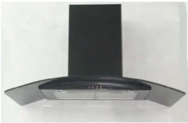
BT9.3 BGL Cooker Hood
90 cm Chimney Hood in black
natural_image
Exterior view of a modern kitchen air conditioner with a black smoke cover and curved top (no text or symbols visible)
NOTE: This User Instruction Manual contains important information, including safety & installation points, which will enable you to get the most out of your appliance. Please keep it in a safe place so that it is easily available for future reference.
CONTENTS
YOUR COOKER HOOD'S SPECIFICATIONS ....3
IMPORTANT SAFETY INFORMATION....4-5
CARING FOR THE ENVIRONMENT......6
USING YOUR COOKER HOOD....7
MAINTAINING AND CLEANING YOUR COOKER HOOD ....8-10
INSTALLATION INSTRUCTIONS ....12-19
ELECTRICAL CONNECTION....12
INSTALLING THE COOKER HOOD......13-15
FITTING THE CHIMNEY....16-17
ATTACHING THE GLASS.....18
INSTALLATION NOTES - EXTRACTION / PURIFYING VERSION .....19
NOTE ON INSTALLING THE VERSION WITH LOWER BRACKET.....20
TROUBLESHOOTING 21
CONDITIONS OF GUARANTEE....22
CONTACT DETAILS....23
HT MOD 16/08/06
Congratulations on purchasing a Baumatic Cooker Hood!
To fully enjoy using your appliance long into the future, please firstly familiarise yourself with its specifications, safety advice and operational instructions included in this manual. You will also need this manual to ensure that your Cooker Hood has been installed properly.
DIMENSIONS
Width (canopy): 900 mm
Depth (canopy): 500 mm
Height (adjustable): 540 mm to 1010 mm
Dimensions of Chimney Section:
260 mm X 350 mm
Your Cooker Hood is fitted with:
• High extraction tangential motor
• Electrical button control operation
- 3 speeds
• 1 metallic grease filter
- 2 lights
Extraction capacity - 500m³/hr
Optional Extra: 1 x Pair of S1 Carbon filters for air recirculation.
Important Safety Information: Please Read this before installing & using.
○ Any installation work must be carried out by a qualified electrician or competent person.
The hood must be installed in accordance with the installation instructions and all measurements followed.
○ If the cooker hood is installed for use above a gas appliance then the provision for ventilation must be in accordance with the Gas Safety Codes of Practice BS.6172, BS.5440 & BS.6891 (Natural Gas) and BS.5482 (LP Gas) 1994, the Gas Safety (Installation & Use) Regulations, the Building Regulations issued by the Department of the Environment, the Building Standards (Scotland) (Consolidated) Regulations issued by the Scottish Development Dptmt.
- It is dangerous to alter the specifications or to modify this product in any way. Do not tamper with it or attempt to alter it in the attempt to customise it further.
- When installing the hood, ensure that the following recommended distances are being observed between the cooker top and the bottom of the cooker hood:
√ Electric cookers: 700 mm
√ Gas cookers: 700 mm
√ Coal/ oil cookers: 800 mm
* NOTE - DO NOT SET YOUR COOKER HOOD LESS THAN 700mm ABOVE YOUR COOKER!
- When installed between adjoining wall cabinets, the cabinets must not overhang the hob.
- The edges of the cooker hood are sharp – be mindful of this as you handle your appliance, especially during installation and cleaning. DO NOT CLEAN IN BEHIND THE GREASE FILTERS!
- If the room where the cooker hood is to be used contains a fuel burning appliance such as a central heating boiler then its flue must be of the sealed or balanced flue type.
- If other types of flue or appliances are fitted, ensure that there is an adequate supply of air in the room.
- When the hood is being used in its extractor function, ensure that the ducting is fire retardant and that there are no bends sharper than 90 degrees as this will reduce the efficiency of the hood.
O
Important Safety Information: Please Read this before installing & using.
- Ensure the ducting for the extractor function has the same diameter as the outlet hole all the way through.
- Keep young children from using, playing with or tampering with the cooker hood. Older children and infirm persons should be supervised if they are using the cooker hood.
- Your cooker hood is for domestic use only.
- Please dispose of the packing material carefully – children are especially vulnerable to it.
○ Dirty oil is an even greater fire risk.
○ Always put lids on pots and pans when cooking on a gas cooker.
The manufacturer refuses to accept any responsibility for damages arising to the hood or it's catching on fire from failure to observe fire safety advice in these instructions.
Remember that when in extraction mode, your cooker hood is removing air from your room. Ensure that proper
ventilation measures are being observed. Note that it removes odours from your room, not steam.
○ Warning - Always ensure that the cooker hood has been disconnected from the power supply before carrying out any work on the hood, including replacing light bulbs.
☒ Do not connect the ducting system of this appliance to any existing ventilation system which is being used for any other purpose.
☒ Do not install above a cooker with a high level grill.
☒ Never leave frying pans unattended during use as overheated fats and oils might catch fire.
☒ Do not leave naked flames under the cooker hood.
☒ Do not attempt to use the cooker hood if it is damaged in any way. Never attempt to use it without the grease filters fitted or if the filters are excessively greasy!
☒ Never flambé cook under this cooker hood.
Environmental Note
Note: Before discarding an old appliance, switch off and disconnect it from the power supply. Cut off and render any plug useless. Cut the cable off directly behind the appliance to prevent misuse. This should be undertaken by a competent person.
CONFORMITY TO W.E.E.E. DIRECTIVE
This appliance is marked according to the European directive 2002/96/EC on Waste electrical and Electronic Equipment (WEEE). By ensuring this product is disposed of correctly, you will help prevent potential negative consequences for the environment and human health, which could otherwise be caused by inappropriate waste handling of this product.
The symbol

on the product, or on the documents accompanying the product, indicates that this appliance may not be treated as household waste. Instead it shall be handed over to the applicable collection point for the recycling of electrical and electronic equipment.
Disposal must be carried out in accordance with local environmental regulations for waste disposal.
For more detailed information about treatment, recovery and recycling of this product, please contact your local city office, your household waste disposal service or the shop where you purchased the product.

natural_image
Simple line drawing of a trash bin with no text or symbolsTo use your cooker hood:
1) Make sure it has been properly installed.
2) Find the CONTROL PANEL. It is located at the front of the canopy, to the right.
3) The CONTROL PANEL contains buttons as shown in the Figure below. These perform separate functions. You will need to understand what these buttons do before you attempt to use your cooker hood.
* Note: The hood should be switched on at least as soon as you start cooking.
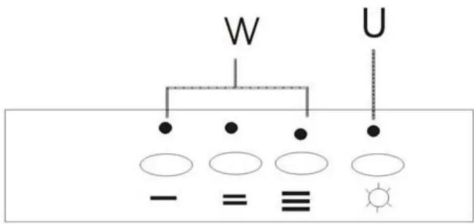
KEY
'W' - Motor operation:
- = low speed, ≡ = mid speed, ≡ = high speed.
'U' – Light 'on/ off' button-This button controls the light
PLEASE NOTE THAT YOUR BAUMATIC COOKER HOOD CAN BE USED EITHER IN RECIRCULATION MODE OR IN EXTRACTION MODE. TO USE THE HOOD IN RECIRCULATION MODE, YOU WILL NEED TO FIT THE CARBON FILTERS. (SEE PAGE 11)
Cleaning your Baumatic Cooker Hood:
IMPORTANT: Before cleaning, always ensure that you have switched your cooker hood OFF at the omni-polar switch, set at the wall from the cable:
Cleaning
- Clean the external parts with mild liquid detergents on a damp cloth.
Never use abrasive powder, corrosive solvents or brushes.
Never insert pointed objects into the motor's protective grid. -
Only clean the control panel and filter grill with a damp cloth and delicate detergents.
-
Be sure to replace the carbon filters at the recommended intervals. Build up could cause a fire hazard.
Never take out the grease filters and attempt to clean the space above where they are set.
Anti-Grease Grille
- Your cooker hood includes an anti-grease grille which helps absorb vapour-suspended grease particles to protect your kitchen & furniture from greasy residues.
The metal grille may become inflammable if it becomes saturated with greasy residue.
√ To prevent this fire hazard, the grille should be cleaned regularly (depending on use) every 10-15 days and at least once a month in hot water with normal washing-up detergent. DO NOT USE A DISHWASHER TO ACHIEVE THIS.
natural_image
Close-up of a finger pressing a button on a green and white electronic device (no text or symbols visible)
natural_image
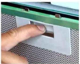
Simple line drawing of a cylindrical object placed on a base with a grid pattern below (no text or symbols)First remove the grille by pulling down on it. Undo the side catches.
You can now clean the anti-grease filter grilles.
√ Soak them for about one hour in hot water with a grease-loosening detergent then rinse off thoroughly with hot water.
√ Repeat the process if needed. Refit the grease grille once it has dried.
√ Refit the grease grilles when dry.
√ PLEASE NOTE: DISCOLOURATION OF THE GREASE FILTER CAN TAKE PLACE WHEN CLEANED IN A DISHWASHER, ETC. Do not worry about the slight discolouration of the grille –its performance won’t be affected.
Let the filter grilles dry thoroughly before refitting them.
Maintenance – Changing the Light Bulb and Carbon Filter
a) Changing the light bulb
Before changing the light bulb, ensure that the appliance is not live (i.e., ensure that you have been checked it off at the
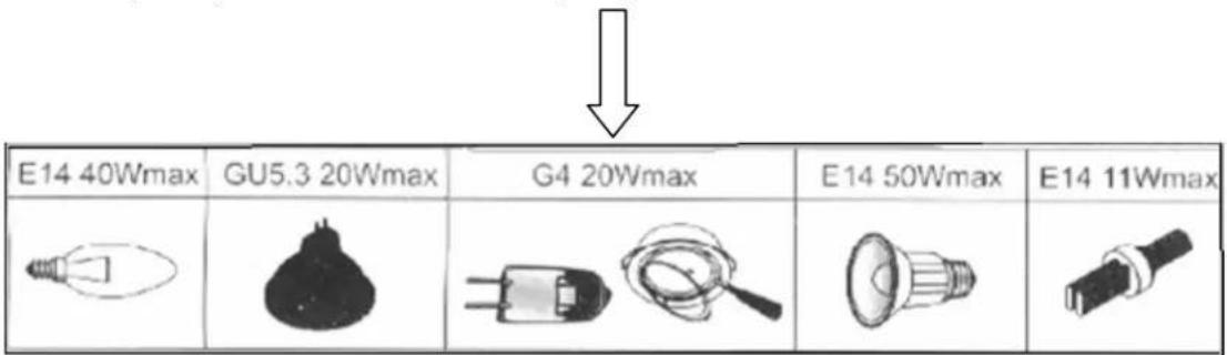
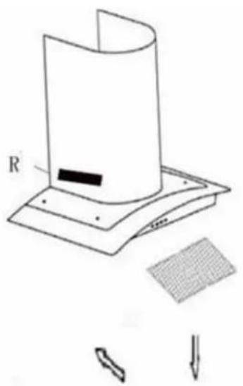
√ Remove the metal anti-grease filters (see Figure 2 below) and find the old bulb located with the light fixture up inside the exposed canopy. Change the halogen b using only olive-shaped spares with an G4 coupling, max. 20W.
natural_image
Diagram of a cylindrical device with labeled component R and a grid pattern, showing no readable text or symbols.Fig 2
* PLEASE NOTE - Defective bulbs should be replaced immediately.
√ Replace the metal anti-grease filters.
Installing / Changing the Carbon Filter
Installing / Changing the Carbon Filter.
Your Baumatic Cooker Hood uses a pair of CARBON FILTERS to purify the air for the air recirculation function.
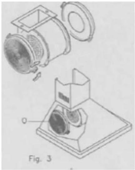
You will find that the filters will attach to both sides of the fan motor (please see figures at bottom of page).
The active carbon filters must be replaced regularly, at least once every three months, to allow normal operation.
Before starting to fit the carbon filter, turn the omni-polar switch off at the wall.
natural_image
Technical line drawing of a mechanical device with exploded and assembled views (no text or symbols)CHANGING THE CARBON FILTER
1) Press the handle of the metal grease filter towards the rear part of the unit until it is released from the front housing, and remove it by pressing downwards (Fig. 2 - above).
2) Remove the old carbon filters by twisting them anticlockwise until they unlatch from the sides of the motor.
3) Blackable new carbon filter have two fixing tongues), turning clockwise so that the tongues latch onto the motor's sides. (Fig. 3 - left).
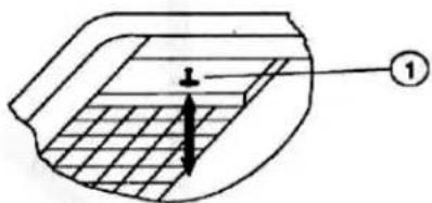
FIG. 2

4) Reposition the anti-grease metallic filter grilles.
INSTALLATION INSTRUCTIONS – Electrical Connection.
Before installation and usage, read all the instructions and make sure that voltage z) indicated on the identification plate (found e (V) and the frequency (H inside your Cooker Hood) and all the data inside the appliance are exactly the same as the voltage and frequency in your home.
NOTE: The manufacturer declines all responsibility in the event of failure to observe all the accident-prevention regulations in force which are necessary for normal use and regu operation of the electric system.
ELECTRICAL CONNECTION
Your cooker hood is intended for fitted and permanent installation.
- The power cable must be connected to the terminals marked L (live) and N (neutral) in the hood and fixed with a cable clamp. distance of at least 3m
- The cooker hood's power cable must be fitted upstream from the electrical connection using an omni-polar switch with a contact
We recommend that the appliance is connected by a qualified electrician who is a member of the N.I.C.E.I.C. and who will comply with the I.E.E. and local regulations. The wires in the mains lead are coloured in accordance with the following U.K. code:
Blue= Neutral, Brown = Live, Green/ Yellow = Ground
If you can only find two wires in the cable (blue and brown), neither must be connected to the Earth terminal!
- As the colours of the wires in the appliance's mains lead may not correspond with the coloured markings identifying the terminals in your spur box, please proceed as follows:
1) The BLUE WIRE must be connected to the terminal marked "N" (Neutral), or coloured Black
2) The BROWN WIRE must be connected to the terminal marked "L" (LIVE), or coloured Red
3) The Green/ Yellow wire must be connected to the terminal marked "E" or
1- (Earth)(Fig 7 - at left)
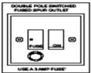
Fig. 7 ONLY FOR U.K.
(Wire diagram-at right)
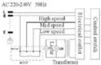
flowchart
graph TD
    A["AC 220-240V 50Hz"] --> B["L"]
    A --> C["N"]
    A --> D["E"]
    B --> E["Motor"]
    C --> E
    D --> E
    E --> F["Transformer"]
    F --> G["Electrical outlet"]
    G --> H["Control switch"]
    F --> I["High speed"]
    F --> J["Mid speed"]
    F --> K["Low speed"]
INSTALLATION INSTRUCTIONS – Installing your Cooker Hood

PLEASE NOTE THAT YOU WILL HAVE TO DECIDE BEFORE INSTALLING YOUR COOKER HOOD THAT YOU CAN ADAPT IT AS AN EXTRACTION FAN. PLEASE SEE PAGE 18 NOW TO UNDERSTAND CRUCIAL DIFFERENCES IN THESE.
☒ The cooker hood must not be fitted above stoves with a radiant top plate.
☒ We recommend that at least two people install this hood.
NOTE: Your Baumatic Cooker Hood should only be fitted on a wall. Do NOT position it any less than 700 mm (70 cm) above the hob.
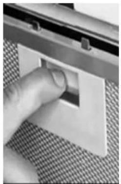
1) Remove the metal anti-grease filters (See figure at right).
Anti - Grease Filter
natural_image
Close-up of a hand pressing a small rectangular object on a textured surface (no visible text or symbols)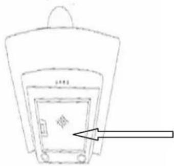
natural_image
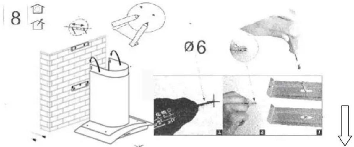
Simple line drawing of a backpack with an arrow pointing to the front panel (no text or symbols)2) Position the hood against the wall and mark the position of the support holes that are to be drilled as shown in the figure below. These support holes can be found on Fig. 4 on next page marked as 'D' with the anchoring holes marked as 'E' (Fig. 4 on next page). If you hood comes with an attached jig, use that as a guide to make the marks for the screw holes.
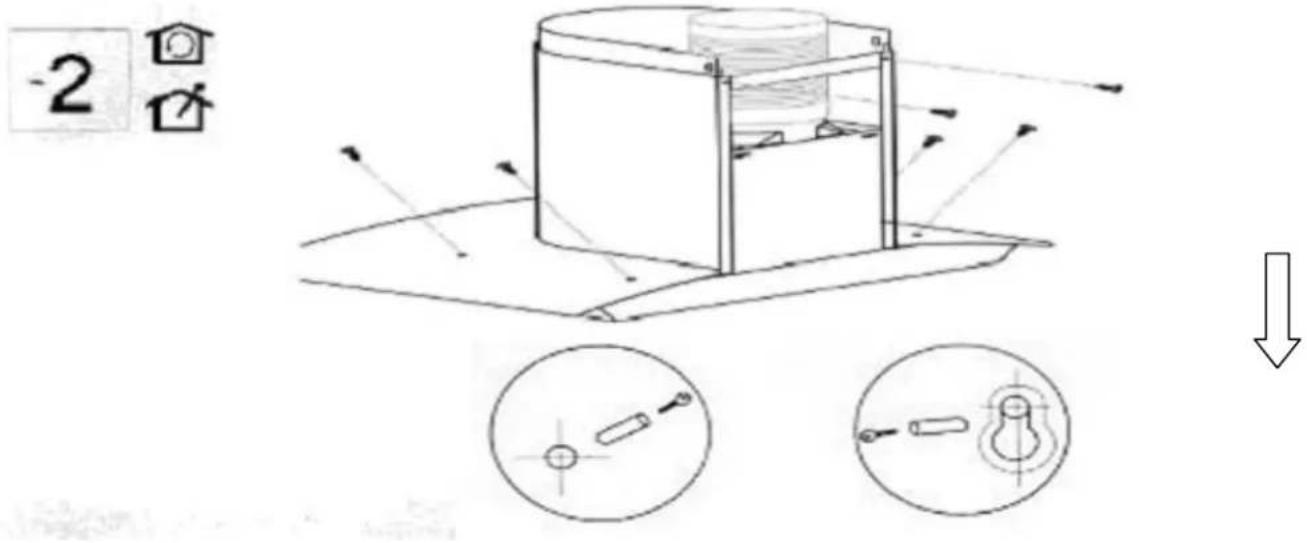
INSTALLATION INSTRUCTIONS – Attaching the Hood
3) Using a drill bit with a 6 mm diameter, make holes in the wall where you have marked these positions (see below).
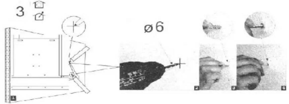
4) Insert the expansion fixings (rawl plugs) in the holes and then screw the support screws halfway in (see below figure, at right).
4
natural_image
Technical line drawing of a cylindrical tank mounted on a base, next to a brick wall and a wall-mounted bracket (no text or symbols)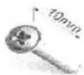

natural_image
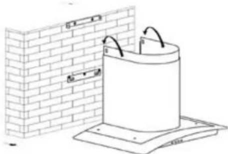
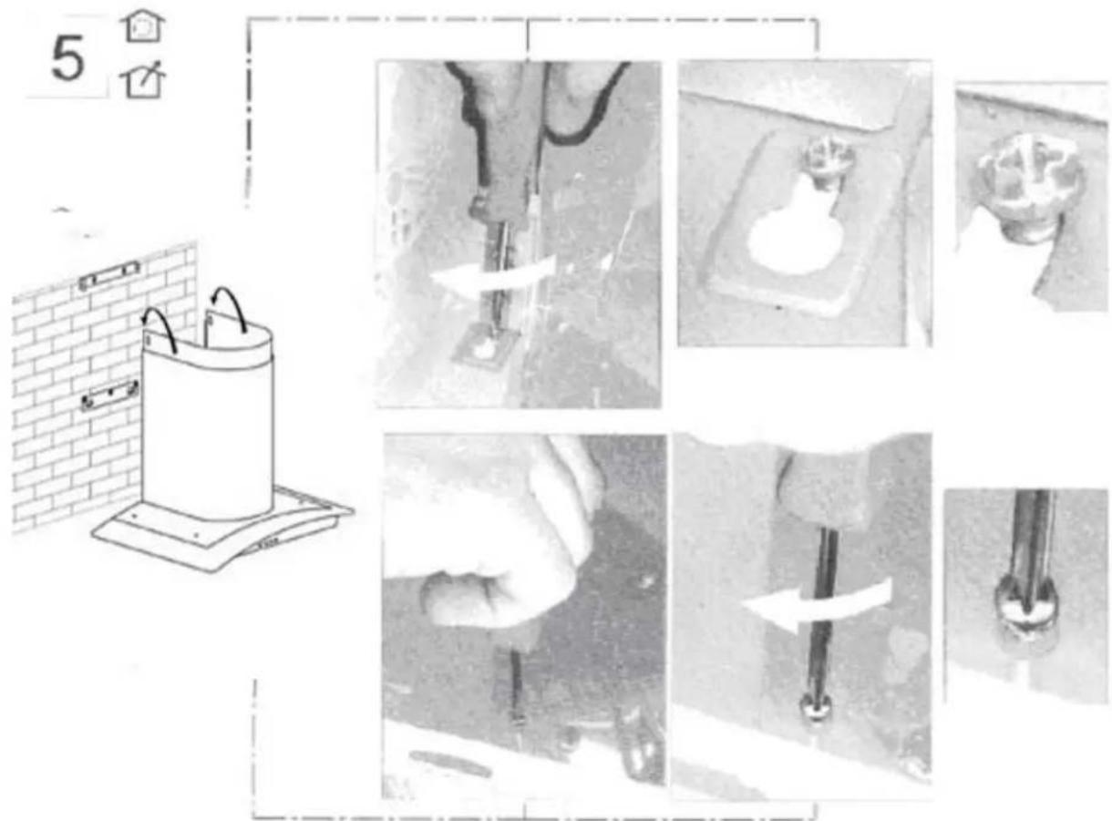
Simple line drawing of a mechanical component or tool with no visible text or symbols5) Hook the hood onto the screws (see above figure) and fasten it onto the wall, tightening the support and anchoring screws the rest of the way in (next page, at top.)
INSTALLATION INSTRUCTIONS – Attaching the Hood
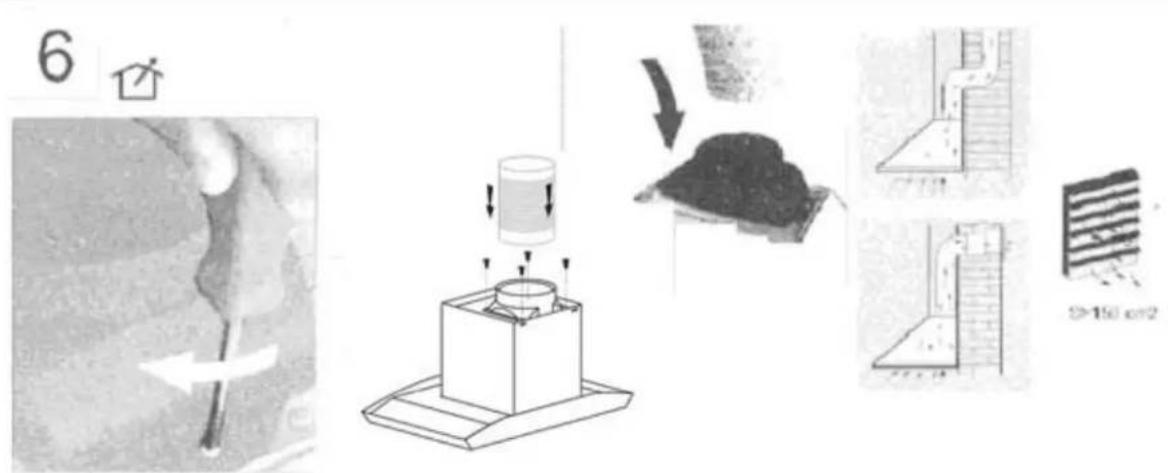
6) (EXTRACTION FUNCTION ONLY) Connect the coupling to the top of the cooker hood (see below). Then connect the discharge pipe to the coupling as shown below. Remember that your ducting will have to match the specifications shown in the notes on Extraction / Air Purifier (Recirculation) Modes on p.18.
INSTALLATION INSTRUCTIONS – Fitting the Chimney
FI TTING THE PIPE – Once your Cooker Hood has been installed, you can now fit the pipe.
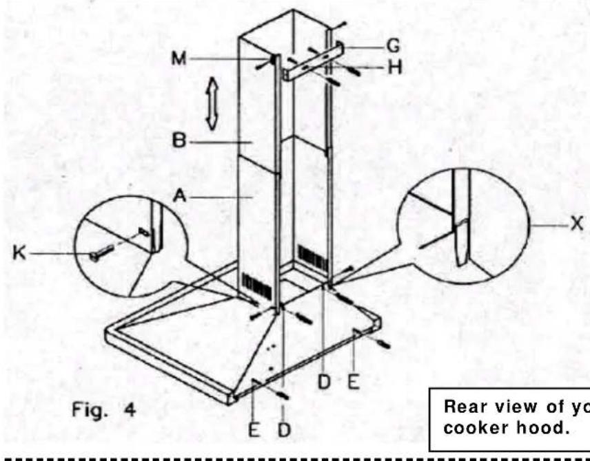
1) Take the two casings 'A' and 'B':
2) Rest the bottom of the casing 'A' on the top of the hood, taking care to position the tabs of the casing correctly on the back of the hood as shown as part 'X' in Figure 4 at right.
3) Fix casing 'A' onto the hood using the two screws 'K' supplied in the bag of accessories (Figure 4 – at right).

4) Lift the mobile part 'B' until it reaches the ceiling, checking that it is perpendicular to the hood.
5) Mark the side measurement of the mobile casing 'B' and then lower it (see below).

INSTALLATION INSTRUCTIONS – Fitting the Chimney
6) T ake the fixing bracket 'G' (Fig. 4 – previous page), centre it with respect to the mark you previously made, keeping it in contact with the ceiling, and then mark the anch ('H').
7) Using a drill bit with a 6m m diameter, make two holes on the fixing marks you previously made (see below).
8) Insert the expansion fixings (rawlplugs) provided, put bracket 'G' (see Fig. 4 on previous page) in position and secure it with the screws provided.
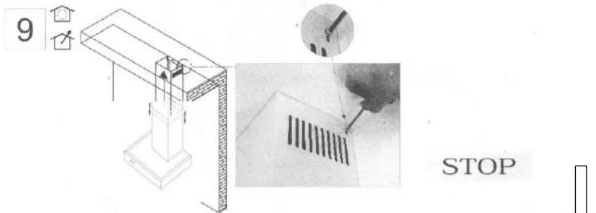
9) Lift casing 'B' up to the ceiling and secure it to the bracket 'G', inserting the screws provided in the holes 'M' (Fig. 4 – previous page).
ATTACHING THE GLASS
Remove the metal grease filters from the hood
Slacken both anchoring screws "F"
Place the glass 'Q' on the upper shelf of the hood, pushing it in towards the wall.
- Tightening the screws 'F' again in the hole and connecting them to the unit.
Take care that the anchoring corner is firmly fastened, tightening it well.
Re-insert the ventilation tube with the coupling tube 'N'.
PLEASE NOTE * DO NOT OVERTIGHTEN THESE SCREWS OR YOU MAY DAMAGE / DI STORT THE UNIT.

Extraction / Air Purifier Modes of Operation
EXTRACTION OPERATION – Installation Instructions
- Ensure that you have fitted the union ('N') to the upper part of the hood using the packaged two screws supplied inside the packing (Fig. 1- on right). Using a 125 mm diameter pipe, connect the union (N) on the upper part of the ho (see Fig. 1) to the discharge outlet for cooking vapours with a cross-section of at least 150 cm ^2 .
PLEASE NOTE: If there is no discharge outlet and the hood is to be fitted to an outside wall of the building, make a hole in the wa that is enough to fit a wind and rain-proof shutter with a cross section of at least 150 cm ^2 and connect this to the outlet union of the unit by means of a pipe.
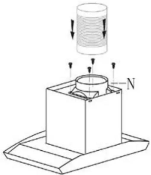
Fig. 1
natural_image
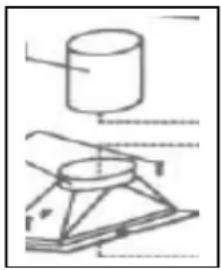
Technical diagram showing a cylindrical object and a mechanical component with no visible text or symbolsPlease note: For the extraction function, you will need to connect a 125 mm diameter outlet chimney to the spigot 'N' in fig. 1 above. This pipe is not provided with your cooker hood. See figure on left.
AIR PURIFIER (RECI RCULATION) OPERATION - Installation Instructions
The cooker hood can be converted to work as an air purifier in the event that there is no provision for an external air discharge duct.
In this case, air is recycled through the vent 'R' (Fig. 1 – above). When using the unit as an air purifier, you need to install two active carbon filters to absorb cooking vapours (please see page 11).
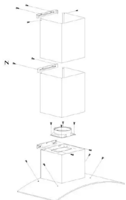
If your Cooker Hood comes with a Lower Bracket
* Note on what to do if your Cooker Hood is the version that comes with a BRACKET.
Please note that your cooker hood may include a lower bracket. If this is the case, you will need to have it installed as such.
This will mean a slight change in how the cooker hood is to be installed from the process shown on page 13.
In Fig. 6, below, you will see an exploded view of the cooker hood and (inset), the bracketed connecting area of the hood ('N').
Hook or attach the hood to the bracket using the screws supplied and carefully check that it has been done properly. A few hoods may be supplied with specific screws for vertical or horizontal adjustment.
Fig.6
Troubleshooting
If something has gone wrong with your Cooker Hood, checking against this chart might keep you from having to call for service.
| Symptom | Solution |
| The cooker hood will not start! | Check that the hood is connected to the electricity supply.Check that the fan speed control is set properly. |
| The cooker hood is not working effectively! | The fan speed is not set high enough.The grease filter is dirty.The kitchen is not ventilated well enough.If the hood is set for recirculation, check that the carbon filters have not expired.If the hood is set for extraction, check that the ducting and outlets are not blocked. |
| The cooker hood has switched off during operation! | The safety cut-out device has been tripped.Turn off the hob and then wait for the device to reset.Note that if you have installed your cooker hood too low, this will happen. If it happens frequently, it will be damaged. |
Baumatic Ltd. Conditions of guarantee
Dear Customer,
Your new Baumatic appliance comes complete with a free 12 month guarantee covering both parts and labour costs resulting from defective materials or workmanship.
Baumatic also gives you the opportunity to automatically extend the guarantee period for a further 12 months at no extra cost, giving an initial guarantee period of 24 months. The extended guarantee period applies to England, Scotland, Wales and Northern Ireland only.
To qualify for your full 24 months guarantee you must register your appliance within 28 days of purchase to be covered under this guarantee. This can be done online via: www.baumatic.co.uk or through returning the guarantee card which can be found in each new Baumatic appliance.
* In addition, your appliance is covered by a 5 year parts warranty. Baumatic Ltd will provide free of charge the parts required to repair the appliance, only if they are fitted by a Baumatic engineer, for any defect that arises due to faulty materials or workmanship within a period of 5 years from the original purchase date.
* An additional 1 to 3 year insurance scheme for labour is available should you wish to extend the warranty period.
Should any person other than an authorised representative of Baumatic Ltd interfere with the appliance, the policy is negated and Baumatic Ltd will be under no further liability.
The guarantee covers the appliance for normal domestic use only, unless otherwise stated.
Any claims made under the terms of the guarantee must be supported by the original invoice/bill of sale issued at the time of purchase.
This guarantee is transferable only with the written consent of Baumatic Ltd.
If the appliance fails and is considered either not repairable or uneconomical to repair between 12 months (2 years if registered) and five years, a free of charge replacement will not be offered.
The guarantee for any replacement will only be for the remainder of the guarantee on the original product purchased.
The guarantee does not cover:
- Sinks and taps
- Failure to comply with the manufacturers instructions for use.
- The replacement of cosmetic components of accessories
- Accidental damage or wilful abuse.
- Subsequent loss or damage owing to the failure of the appliance or electrical supply
- Incorrect installation
- Losses caused by Acts of God, civil war, failure to obtain spare parts, strikes or lockouts
- Filters, fuses, light bulbs, external hoses, damage to bodywork, paintwork, plastic items, covers, baskets, trays, shelves, burner bases, burner caps, decals, corrosion, rubber seals.
In the course of the work carried out it may be necessary to remove the appliance from it operating position. Whilst all reasonable care will be taken, Baumatic Ltd cannot accept responsibility for damage sustained to any property whatsoever in this process.
This guarantee is in addition to and does not diminish your statutory or legal rights.
Contacting Baumatic Ltd
| Sales | Service | Spares | Technical/Advice | |
| TEL: 0118 933 6900 | TEL: 0118 933 6911 | TEL: 0118 933 6922 | 0118 933 6933 | |
| FAX: 0118 931 0035 | FAX: 0118 986 9124 | FAX: 0118 933 6942 | 0118 933 6942 | |
For ROI (Republic of Ireland), please contact one of the numbers below:
TEL: 01-6266798 FAX: 01-6266634
Thanks you for buying Baumatic.
* Applies to UK, Scotland, Wales & Northern Ireland only (Republic of Ireland has 1 year labour & 1 year parts warranty only)
Baumatic®
You will be mine ...
Headquarters
Baumatic Ltd.
Baumatic Buildings,
6 Bennet Road,
Reading,
Berkshire
RG2 0QX, United Kingdom
Sales Telephone
+44 118 933 6900
Sales Fax
+44 118 931 0035
Service Telephone
+44 118 933 6911
Service Fax
+44 118 986 9124
Spares Telephone
+44 118 933 6922
Technical / Advice Telephone
+44 118 933 6933
E-mail:
sales@baumatic.co.uk
technical@baumatic.co.uk
Http (Internet site):
www.baumatic.com

www.baumatic.com
- BT9.3 BGL Cooker Hood
- User Manual for your Baumatic
- CONTENTS
- Congratulations on purchasing a Baumatic Cooker Hood!
- DIMENSIONS
- Dimensions of Chimney Section:
- Your Cooker Hood is fitted with:
- Important Safety Information: Please Read this before installing & using.
- Environmental Note
- CONFORMITY TO W.E.E.E. DIRECTIVE
- The symbol
- To use your cooker hood:
- Cleaning your Baumatic Cooker Hood:
- Cleaning
- Anti-Grease Grille
- Maintenance – Changing the Light Bulb and Carbon Filter
- a) Changing the light bulb
- Installing / Changing the Carbon Filter
- Installing / Changing the Carbon Filter.
- INSTALLATION INSTRUCTIONS – Electrical Connection.
- ELECTRICAL CONNECTION
- INSTALLATION INSTRUCTIONS – Installing your Cooker Hood
- INSTALLATION INSTRUCTIONS – Attaching the Hood
- INSTALLATION INSTRUCTIONS – Fitting the Chimney
- FI TTING THE PIPE – Once your Cooker Hood has been installed, you can now fit the pipe.
- ATTACHING THE GLASS
- Extraction / Air Purifier Modes of Operation
- EXTRACTION OPERATION – Installation Instructions
- AIR PURIFIER (RECI RCULATION) OPERATION - Installation Instructions
- If your Cooker Hood comes with a Lower Bracket
- Troubleshooting
- Baumatic Ltd. Conditions of guarantee
- Contacting Baumatic Ltd
- Baumatic®
- Headquarters
- E-mail:
Brand : BAUMATIC
Model : BT9.3BGL
Category : Range hood