57380 - Uncategorized HYUNDAI - Free user manual and instructions
Find the device manual for free 57380 HYUNDAI in PDF.

User questions about 57380 HYUNDAI
0 question about this device. Answer the ones you know or ask your own.
Ask a new question about this device
Download the instructions for your Uncategorized in PDF format for free! Find your manual 57380 - HYUNDAI and take your electronic device back in hand. On this page are published all the documents necessary for the use of your device. 57380 by HYUNDAI.
USER MANUAL 57380 HYUNDAI
natural_image
Industrial portable push tool with yellow spring and black handle (no visible text or symbols)CONTENT
I. INTRODUCTION ...... - 2 -
II.SAFETY&ALERT SYMBOLS - 2 -
2.1 SAFETY SYMBOLS.... - 3 -
2.2 HAZARDS SYMBOLS....- 3 -
2.3 GENERAL SAFETY - 5 -
2.4 TRANSPORTING.... - 7 -
2.5 MAINTENANCE - 7 -
2.6 EMERGENCIES.... - 7 -
III. GENERAL INFORMATION...... - 8 -
3.1 DEFINITION.... - 8 -
3.2 CONSTRUCTION.... - 8 -
3.3 CONTROLS....-8-
3.4 BASIC ENGINE.... - 10 -
IV. OPERATION .... - 11 -
4.1 CHECK SPRING CYLINDER OIL BATH - 11 -
4.2 CHECK ENGINE - 12 -
4.3 INSPECTION - 12 -
4.4 START - 13 -
4.5 STOP ENGINE ...... - 16 -
To reduce the risk of injury, all operators and maintenance personnel must read and understand these instructions before operating, changing accessories, or performing maintenance on power equipment. All possible situations cannot be covered in these instructions. Care must be exercised by everyone using, maintaining or working near this equipment.
I. INTRODUCTION
Thank you for your selection of our equipment.
We have taken care in the design, manufacture and testing of this product. Should service or spare parts be required, prompt and efficient service is available from our branches.
General Safety instructions for the Operation of Power Equipment. Our factory's goal is to produce power equipment that helps the operator work safely and efficiently. The most important safety device for this or any tool is the operator. Care and good judgment are the best protection against injury. All possible hazards cannot be covered here, but we have tried to highlight some of the important items, individuals should look for and obey Caution, Warning and Danger signs placed on equipment, and displayed in the workplace. Operators should read and follow safety instructions packed with each product.
Learn how each machine works. Even if you have previously used similar machines, carefully check out each machine before you use it. Get the “feel” of it and know its capabilities, limitations, potential hazards, how it operates, and how it stops. We has no duty if person don’t operate as instruction said.
II.SAFETY&ALERT SYMBOLS
FOR YOUR SAFETY AND THE SAFETY OF OTHERS!
Safety precautions should be followed all the time when operating this equipment. Failure to read and understand the Safety Messages and Operating Instructions could result in injury to yourself and others.


NOTE
This Operating Instructions has been developed to provide complete instructions for the safe and efficient operation of the Tamping Rammer. Refer to the engine manufactures instructions for data relative to its safe operation.
Before using this rammer, ensure that the operating individual has read and understood all instructions in this manual.
2.1 SAFETY SYMBOLS
The three (3) Safety Messages shown below will inform you about potential hazards that could injure you or others. The three Safety Messages specifically address the level of exposure to the operator, and are preceded by one of three words: DANGER, WARNING and CAUTION.

DANGER
You WILL be KILLED or SERIOUSLY INJURED if you DO NOT follow these directions.

WARNING
You CAN be KILLED or SERIOUSLY INJURED if you DO NOT follow these directions.

CAUTION
You CAN be INJURED if you DO NOT follow these directions.
2.2 HAZARDS SYMBOLS
Potential hazards associated with the operation of a Tamping Rammer will be referenced with Hazard Symbols which appear throughout this manual, and will be referenced in conjunction with Safety Message Alert Symbols.

WARNING
Lethal Exhaust Gas Hazards
Engine Exhaust gases contain poisonous carbon monoxide. This gas is colorless and odorless, and can cause death if inhaled. NEVER operate this equipment in a confined area or enclosed structure that does not provide ample free flow air.


WARNING
Explosive Fuel Hazards
Gasoline is extremely flammable, and its vapors can cause an explosion if ignited. DO NOT start the engine near spilled fuel or combustible fluids. DO NOT fill the fuel tank while the engine is running or hot. DO NOT overfill tank, since spilled fuel could ignite if it comes into contact with hot engine parts or sparks from the ignition system. Store fuel in approved containers, in well-ventilated areas and be away from sparks and flames.


WARNING
Burn Hazards
Engine components can generate extreme heat. To prevent burns, DO NOT touch these areas while the engine is running or immediately after operations. Never operate the engine with heat shields or heat guards removed.


WARNING
Respiratory Hazards
ALWAYS wear approved respiratory protection when required.


CAUTION
Rotating Parts Hazards
NEVER operate equipment with covers, or guards removed. Keep fingers, hands, hair and clothing away from all moving parts to prevent injury.

CAUTION
Accidental Starting Hazards
ALWAYS place the ON/OFF switch in the OFF position when the rammer is not in use.


CAUTION
Eye and Hearing Hazards
ALWAYS wear approved eye and hearing protection.


CAUTION
Equipment Damage Hazards
Other important messages are provided throughout this manual to help prevent damage to your light tower, other property, or the surrounding environment.

DANGER
Refueling Hazard
Failure to follow instructions in this manual may lead to serious injury or even death! This equipment is to be operated by trained and qualified personnel only! This equipment is for industrial use only.
2.3 GENERAL SAFETY
■ DO NOT operate or service this equipment before reading this entire manual.

■ This equipment should not be operated by persons under 18 years of age.
■ NEVER operate this equipment without proper protective clothing, shatterproof glasses, steel-toed boots and other protective devices required by the job.

natural_image
Five black circular icons representing different workplace safety symbols: boot, helmet, suit, gear, and glove (no text or labels)■ NEVER operate this equipment when not feeling well due to fatigue, illness or taking medicine.
■ NEVER operate this equipment under the influence of drugs or alcohol.

■ ALWAYS wear proper respiratory (mask), hearing and eye protection equipment when operating the rammer.
■ Whenever necessary, replace nameplate, operation and safety decals when they become difficult read.
■ Manufacturer does not assume responsibility for any accident due to equipment modifications.
■ NEVER use accessories or attachments, which are not recommended for this equipment. Damage to the equipment and/or injury to user may result.
■ NEVER touch the hot exhaust manifold, muffler or cylinder. Allow these parts to cool before servicing engine or rammer.

■ High Temperatures – Allow the engine to cool before adding fuel or performing service and maintenance functions. Contact with hot components can cause serious burns.
The engine section of this rammer requires an adequate free flow of cooling air. NEVER operate the rammer in any enclosed or narrow area where free flow of the air is restricted it will cause serious damage to the rammer or engine and may cause injury to people. Remember the rammer's engine gives off DEADLY carbon monoxide gas.

■ ALWAYS refuel in a well-ventilated area, away from sparks and open flames.
■ ALWAYS use extreme caution when working with flammable liquids. When refueling, stop the engine and allow it cool.
■ NEVER operate the rammer in an explosive atmosphere or near combustible materials. An explosion or fire could result causing severe bodily harm or even death.
■ DO NOT smoke around or near the machine. Fire or explosion could result from fuel vapors, or if fuel is spilled on a hot engine.
■ Topping-off to filter port is dangerous, as it tends to spill fuel.
■ Stop the engine when leaving the rammer unattended.
■ Maintain this equipment in a safe operating condition at all times.
■ ALWAYS stop the engine before servicing, adding fuel and oil.
■ NEVER run engine without air filter. Severe engine may occur.
■ ALWAYS service air cleaner frequently to prevent carburetor malfunctions.
■ ALWAYS check the machine for loosened threads or bolts before starting.
■ ALWAYS be sure the operator is familiar with proper safety precautions and operations techniques before using rammer.
■ ALWAYS store equipment properly when it is not being used. Equipment should be stored in a clean, dry location out of the reach of children.
■ DO NOT operate this equipment unless all guards and safety devices are attached and in place.
■ CAUTION must be exercised while servicing this equipment.
- Keep all inexperienced and unauthorized people away from the equipment at all times.
■ Unauthorized equipment modifications will void all warranties.
■ Test the engine ON/OFF switch before operating. The purpose of this switch is to shut down the engine of the rammer.
- Refer to the Engine User's Manual for engine technical questions or information recommended for the equipment.
2.4 TRANSPORTING
■ ALWAYS shut down engine before transporting.
■ Tighten fuel tank cap securely and close fuel cock to prevent fuel from spilling.
- Drain fuel when transporting rammer over long distances or bad roads.
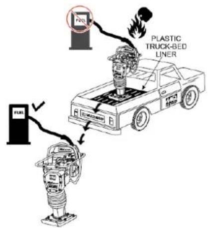
■ When placing the rammer inside a truck-bed for transport, always tie-down the rammer.
2.5 MAINTENANCE
■ NEVER lubricate components or attempt service on a running rammer.
■ ALWAYS allow the rammer a proper amount of time to cool before servicing.
- Keep the rammer in proper running condition.
■ Fix damage to the rammer immediately and always replace broken parts.
■ Dispose of hazardous waste properly. Examples of potentially hazardous waste are used motor oil, fuel and fuel filters.
■ DO NOT use wooden or plastic containers to dispose of hazardous waste.
2.6 EMERGENCIES
■ ALWAYS know the location of the nearest fire extinguisher and first aid kit.

In emergencies always know the location of the nearest phone or keep a phone on the job site. Also know the phone numbers of the nearest ambulance, doctor and fire department. This information will be invaluable in the case of an emergency.

III. GENERAL INFORMATION
3.1 DEFINITION
The tamping rammer is a powerful compacting tool capable of applying a tremendous force in consecutive impacts to a soil surface. Its applications include soil compacting for road, embankments and reservoirs as well as backfilling for gas pipelines, water pipelines and cable installation work.
Circular motion is converted to create impact force. The tamping rammer develops a powerful compacting force at the foot of the rammer. To maintain optimum performance, proper operation and service are essential.
3.2 CONSTRUCTION
The tamping rammer is equipped with an air cooled, four-cycle gasoline engine. Transmission of the power takes place by increasing the engine speed to engage the centrifugal clutch.
3.3 CONTROLS
Before starting the tamping rammer, identify and understand the function of the controls.
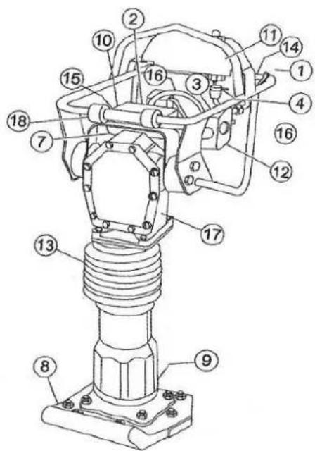
Fig 1
Fig 1 shows the location of the controls and components for the tamping rammer. The function of each control is described below:
- Throttle Lever – Controls engine speed and the tamping action of the rammer.
- Engine Stop Switch –Controls the starting and stopping of the engine. Switch must be in the “ON” position when starting the engine.
- Choke Lever – Used when starting the engine. Normally used in cold weather conditions. In cold weather turn the choke lever to the fully closed position, in warm weather set choke lever half way or completely open.
- Fuel Shut-Off Valve – Supplies fuel from the fuel tank to the engine. To begin fuel flow move the fuel shut-off valve downward.
- Pre-Cleaner – Pre-cleans (first stage) dirt and other debris from entering the engine.
- Foot - Laminated wood with tempered steel plate for superior shock absorption.
- Oil Level Sight Glass – Indicates the level of oil in the oil bath reservoir.
- Recoil Starting Handle - Used when starting the engine. Pull starter handle sharply and quickly, then return starter handle to starter case before releasing.
- Fuel Tank/Cap – Poly fuel tank to avoid rust and corrosion, remove this cap to add gasoline.
- Engine Air Cleaner – Prevents dirt (second stage) and other debris from entering the engine.
- Bellows - Reservoir for oil bath.
- Handle - To operate rammer, grip handle assembly firmly on both sided.
- Muffler - Used to reduce noise and emissions.
- Spark Plug - Provides spark to the ignition system, replace with engine manufacturers recommended type spark plug.
- Nameplate - Displays information regarding the rammer.
3.4 BASIC ENGINE
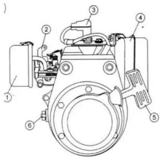
Fig 1A
The engine (Fig 1A) must be checked for proper lubrication and filled with fuel prior to operation. Refer to the Engine User's Manual for instructions.
- Secondary Air Cleaner – Prevents dirt and other debris from entering the fuel system. Remove wing-nut on top of air filter canister to gain access to filter element.
- Choke Lever – Used when starting the engine. Normally used in cold weather conditions. In cold weather turn the choke lever to the fully closed position, in warm weather set choke lever half way or completely open.
- Spark Plug - Provides spark to the ignition system. Set spark plug gap to 0.6-0.7 mm (0.024-0.028 inch). Clean spark plug once a week.
- Muffler - Used to reduce noise and emissions.

WARNING

Engine components can generate extreme heat. To prevent burns, DO NOT touch these areas while the engine is running or immediately after operating. NEVER operate the engine with the muffler removed.
-
Recoil Starter (pull rope) – Manuel-starting method. Pull the starter grip until resistance is felt, then pull briskly and smoothly.
-
Engine ON/OFF Switch – Controls the starting and stopping of the engine. Switch must be in the "ON" position when starting the engine.

NOTE
Operate the engine without an air filter, with a damaged air filter, or a filter in need of replacement will allow dirt to enter the engine, causing rapid engine wear.
IV. OPERATION
This section is intended to assist the operator with the initial start-up of the Tamping Rammer. It's extremely important that this section should be read carefully before attempting to operate the rammer.
DO NOT use your rammer until this section is thoroughly understood.

Read Manual
Failure to understand the operation of the Tamping Rammer could result in severe damage to the trowel or personal injury.
4.1 CHECK SPRING CYLINDER OIL BATH
This unit uses an oil bath lubrication system. Perform the following:
- Check the oil level through the oil level sight glass (Figure 2) at the rear of the tamper foot.
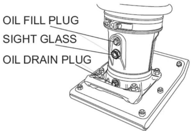
Fig 2
- If oil is not visible, add Mobil ISO VG46 or other oil with same standard into the oil fill plug opening (Fig 2). The bath contains approximately 1000 cc..

The oil level should be kept at the half way point of the sight glass.
4.2 CHECK ENGINE
- Fill the fuel tank (Fig 3) with unleaded gasoline. At the same time, check the engine oil and make it a habit to replenish it often.
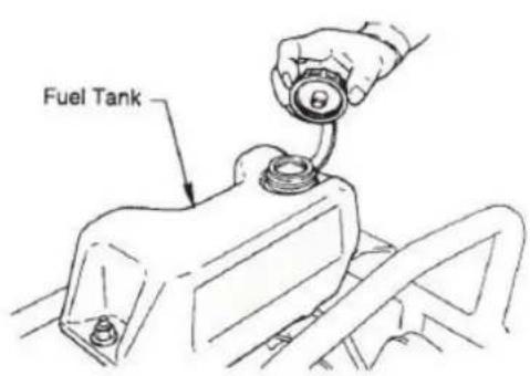
Fig 3
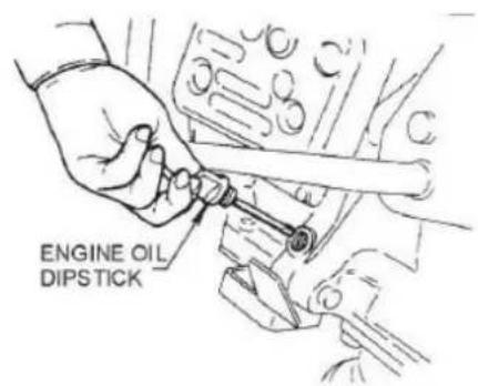
Fig 4
2. Low levels of oil may result in engine seizure due to high levels of consumption during operations.
3. Check the engine oil level (Fig 4) and if the engine oil level is low, it should be refilled. Use the proper motor oil as suggested in the Table below.
| Season or Temperature | Grade of motor oil(higher than MS class) |
| Spring, Summer or Autumn+ 120° F to +15° F | SAE 30 |
| Winter+ 40° F to +15° F | SAE 30 |
| Below +15° F | SAE 10w-30 |
4.3 INSPECTION
- Check all nuts, bolts fasteners for tightness. Retighten as necessary.
- Clean any dirt from the recoil starter and foot pedestal. Wipe the entire unit clean before operating.
- Replace any missing or damage Safety Operations decals.
- Adjust height of handle. Adjust handle by loosening nuts and moving handle to suit operation. Retighten nuts.
4.4 START
- Open the fuel shut-off valve by moving the fuel cock lever to the OPEN position (Fig 5) then set the engine start/stop switch (Fig 5) to the START position.
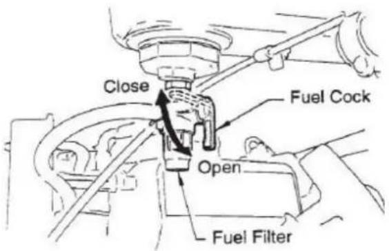
Fig 5
- Set the engine ON/OFF switch (Fig 6) to the ON position (start).
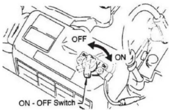
Fig 6
- Close the choke lever (Fig 7) and move the throttle lever to the Full Open position. Turning the choke lever 90 degrees clockwise closes the choke. In cold weather, start the unit with choke fully closed. In warm weather or when the engine is warm, the unit can be started with choke halfway or completely open.
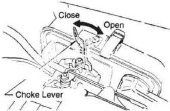
Fig 7
- Grip the recoil starter (Fig 8) handle and pull it until you feel a slight resistance. Then pull sharply and quickly. Return the recoil starter handle to the starter case before releasing.
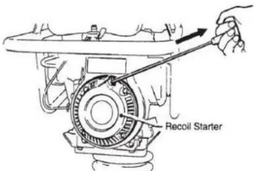
Fig 8
- If engine fails to start, move the choke lever (Fig 7) to the half open position to avoid flooding.
- Repeat steps 1 to 4.
- If the engine does not start after repeated attempts, check the spark plug for excess fuel. Clean and replace the spark plug as needed.
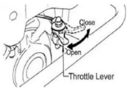
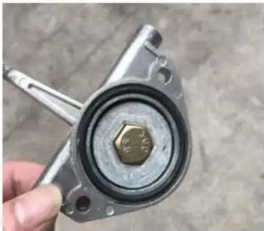
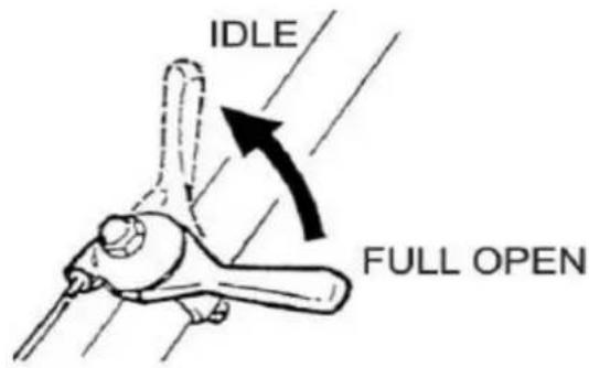
- To start the tamping rammer action, move the throttle lever (Fig 9) quickly from IDLE (close) to the FULL OPEN position. DO NOT move the throttle lever slowly as this may cause damage to the clutch or spring. Please be noted that for NEW TYPE throttle lever, get O-ring from manual and accessories bag and fix in the throttle lever as Fig 10.
OLD TYPE
NEW TYPE
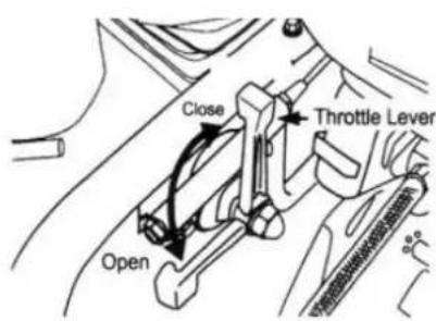
Fig 9
natural_image
Close-up of a hand holding a mechanical component with a hexagonal bolt, no visible text or symbolsFig 10

CAUTION
-
Make sure that the throttle lever is moved to the FULL OPEN position. Operating the rammer at less than full speeds can result in damage to the clutch springs or foot.
-
The Tamping rammer is designed to run at 4.000 rpm. At optimum rpm the foot hits at the rate of 680 impacts per minute. Increasing throttle speed past factory set rpm does not increase impacts and may damage unit. The rammer is designed to advance while tamping. For faster advance, pull back slightly on the handle so that rear of foot contacts soil first.
4.5 STOP ENGINE
Normal Shutdown
- Move throttle lever quickly from the FULL OPEN to IDLE position (Fig 11) and run the engine for three minutes at low speed. After the engine cools, turn the engine start/stop switch to the "STOP" position (Figure 6) until engine comes to a complete stop.
OLD TYPE
NEW TYPE
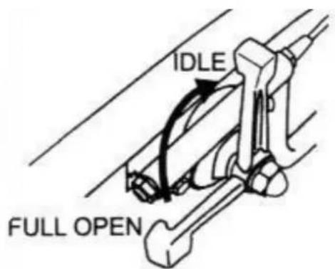
Fig 11
- Close the fuel shut-off valve by moving the fuel cock lever to the CLOSED position. See Figure 5.
Emergency Showdown
Move the throttle lever quickly to the IDLE position, and turn the engine START/STOP switch to the STOP position.
V.MAINTENANCE
DAILY
■ Thoroughly remove dirt and oil from the engine and control area. Clean or replace the air cleaner elements as necessary. Check and retighten all fasteners as necessary. Check the spring box and bellows for oil leaks. Repair or replace as needed.
WEEKLY
■ Remove the fuel filter cap and clean the inside of the fuel tank.
■ Remove or clean the filter at the bottom of the tank.
■ Remove and clean the spark plug, then adjust the spark gap to 0.02\~0.03 inch (0.6\~0.7 mm). This unit has electronic ignition, which requires no adjustments.
■ Clean air cleaner cover.
200 – 300 HOURS
■ Remove the element from the pre-cleaner (Figure 12) at the top of the crankcase (body side) and clean it with cleaning oil (kerosene).

Figure 12 Optional Pre-Cleaner
■ Lubricate the top element (yellow) with 2\~5cc of engine oil SAE-30.
Lubricate bottom element (gray) with 13\~15cc of engine oil SAE-30 and completely squeeze out the excess oil from the element before installing.
The air cleaner (Figure 13) on the engine side will hardly be contaminated, if it is, however after cleaning the element with kerosene, dip it in mixed oil consisting of 3 parts of gasoline and 1 part of engine oil. Then tightly squeeze outer primary element (sponge) and shake off well the inner secondary element before installing them.
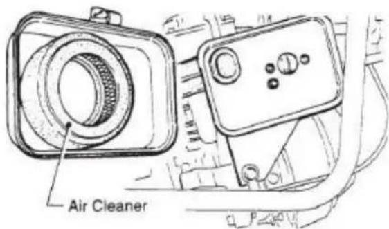
Figure 13 Engine Air Cleaner
200 – 300 HOURS (Oil Bath)
Drain oil reservoir on foot housing (Figure 14). Refill with approximately 1000cc of MOBIL ISO VG-46 or other oil with same standard. Oil should be midway in sight glass. Break in oil should be changed after first 50 hours.
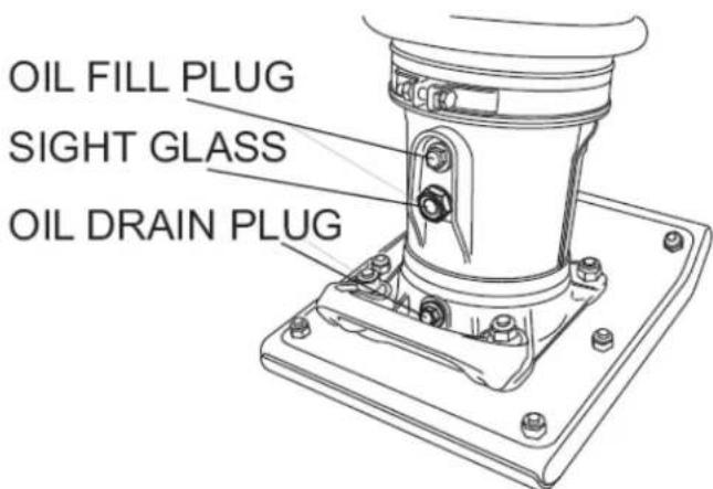
Figure 14 Foot Housing Drain Plug
YEARLY
■ Check the fuel line and the oil line regularly for damage and to ensure that there are no leaks.
■ Replace the oil and fuel lines every two years to maintain the performance and flexibility lines.
LONG TERM STORAGE
■ Drain fuel from fuel tank, fuel line and carburetor.
■ Remove spark plug and pour a few drops of motor oil into cylinder. Crank engine 3 to 4 times so that oil reaches all internal parts.
■ Clean exterior with a cloth soaked in clean oil.
■ Store unit covered with plastic sheet in moisture free and dust free location out of direct sunlight.
VI. TROUBLESHOOTING
6.1 ENGINE TROUBLESHOOTING
| SYMPTOM | POSSIBLE PROBLEM | SOLUTION |
| Difficult to start | ||
| Fuel is available but spark plug will not ignite. (Power available at high tension cable). | Ignition plug being bridge? | Check ignition system. |
| Carbon deposit at ignition? | Clean or replace ignition. | |
| Short circuit due to defective insulators? | Replace insulators. | |
| Improper spark gap? | Set spark plug gap to the correct gap. | |
| Fuel is available but spark plug will not ignite. (Power NOT available at high tension cable). | Short circuit at stop switch | Check stop switch circuit. Replace stop switch if defective. |
| Ignition coil defective? | Replace ignition coil. | |
| Fuel is available and spark plug ignites (compression normal). | Muffler clogged with carbon deposits? | Clean or replace muffler. |
| Fuel in use inadequate (water, dust)? | Flush fuel system and replace with fresh fuel. | |
| Air Cleaner clogged? | Clean or replace air cleaner. | |
| Fuel is available and spark plug ignites (compression low). | Defective cylinder head gasket? | Tighten cylinder head bolts or replace head gasket. |
| Cylinder worn? | Replace cylinder. | |
| Spark plug loose? | Tighten spark plug | |
| Operation not satisfactory | ||
| Not enough power available (compression normal, no misfiring). | Air cleaner clogged? | Clean or replace air cleaner. |
| Air in fuel line? | Bleed (remove air) from fuel line. | |
| Fuel level in carburetor float chamber improper? | Adjust carburetor float. | |
| Carbon deposits in cylinder? | Clean or replace cylinder. | |
| Not enough power available (compression normal, misfiring). | Ignition coil defective? | Flush fuel system and replace with fresh fuel. |
| Ignition plug often shorts? | Clean or replace crankcase. | |
| Fuel in use inadequate (water, dust)? | Clean or replace muffler. | |
| Engine overheats. | Combustion chamber? | Clean or replace crankcase. |
| Exhaust or muffler clogged with carbon. | Clean or replace muffler. | |
| Spark plug heat value incorrect? | Replace spark plug with correct type spark plug. | |
| Rotational speed fluctuates. | Governor adjustment improper? | Adjust governor to correct lever. |
| Governor spring defective? | Clean or replace ignition. | |
| Fuel flow erratic? | Check fuel line. | |
| Air taken in through suction line? | Check suction line. | |
| Recoil starter not working properly. | Dust in rotating part? | Clean recoil starter assembly. |
| Spiral spring failure? | Replace spiral spring. | |
6.2 RAMMER TROUBLESHOOTING
| Engine rotates but amplitude not uniform or does not strike. | Operation speed of throttle lever is incorrectly set? | Set throttle lever to correct position. |
| Oil in excess? | Drain excess oil. Bring to correct level. | |
| Clutch slips? | Replace or adjust clutch. | |
| Spring Failure? | Replace spiral spring. | |
| Speed of engine improper? | Adjust engine speed to correct operating RPM setting. |
VII. REPLACEMENT PARTS LIST
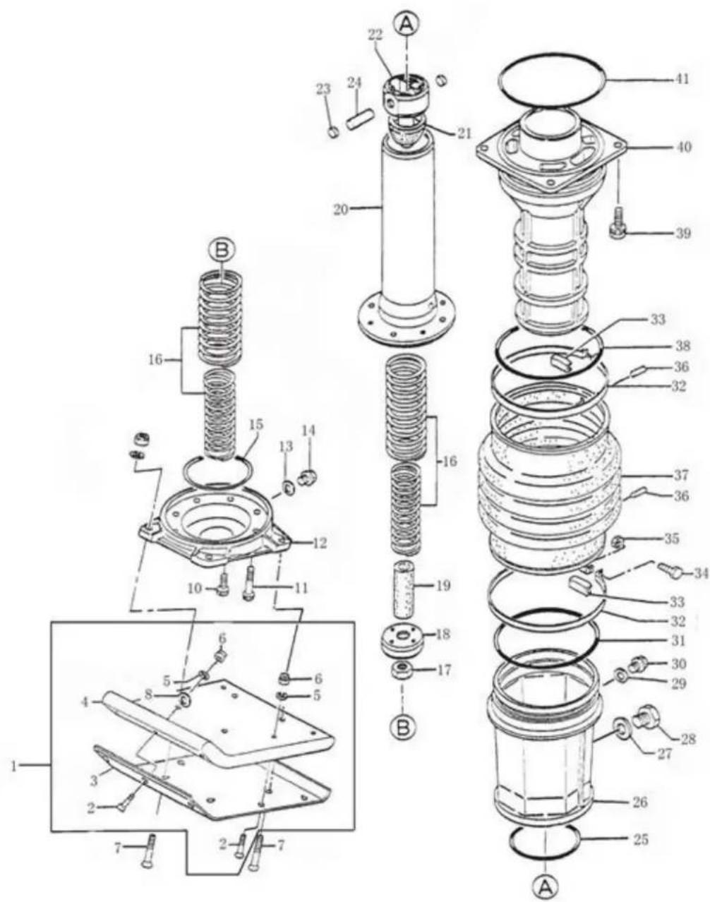
7.1 GUIDE CYLINDER AND FOOT ASSY
GUIDE CYLINDER AND FOOT ASSY(A)
| PART NO. | DESCRIPTION | QTY |
| A01 | Foot Assy | 1 |
| A02 | Sunk head bolt 12*55 H | 7 |
| A03 | Metal sheet | 1 |
| A04 | Plastic Foot | 1 |
| A05 | Washer SW M12 | 11 |
| A06 | Nylon nut M12 | 11 |
| A07 | Sunk head bolt 12*70H( Foot Assy without Handle) | 4 |
| A07 | Sunk head bolt 12*100H( Foot Assy with Handle) | 4 |
| A08 | Washer SW φ12 | 7 |
| A10 | Socket head bolt 10*20T | 4 |
| A11 | Socket head bolt 10*35T | 4 |
| A12 | Foot plate ( for engines except 170F) | 1 |
| A12 | Foot plate ( for 170F) | 1 |
| A13 | Packing φ12(CU) | 1 |
| A14 | Oil plug M12*1.25 | 2 |
| A15 | O-ring G-90 | 1 |
| A16 | Main spring | 1 |
| Inner spring (engines except Honda GX100&170F) | 2 | |
| Inner spring (for Honda GX100& 170F) | 2 | |
| Out spring | 2 | |
| A17 | Nut M18,P1.5 | 1 |
| A18 | Piston end | 1 |
| A19 | Stopper lower | 1 |
| A20 | Spring cylinder | 1 |
| A21 | Stopper upper | 1 |
| A22 | Piston rod kit | 1 |
| A23 | Nylon plug | 2 |
| A24 | Piston pin | 1 |
| A25 | O-ring φ100×3.1 | 2 |
| A26 | Protection sleeve | 1 |
| A27 | Copper packing φ16 | 1 |
| A28 | Level gauge, plug type | 1 |
| A29 | Packing φ12 | 2 |
| A30 | Plug 1/4*14 13L | 2 |
| A31 | O ring 160*4 | 1 |
| A32 | Bellows clamp | 2 |
| A33 | Band guide,bellows | 2 |
| A34 | Bolt 8*40H | 2 |
| A35 | Nut M8 | 2 |
| A36 | Pin 6D-8.5L | 1 |
| A37 | Chinese made bellow | 1 |
| A37 | German made bellow (Optional) | 1 |
| A38 | O ring 160*4 | 1 |
| A39 | Bolt 10*35 H,SW | 4 |
| A40 | Guide cylinder | 1 |
| A41 | O-ring φ 160×5.3 | 1 |
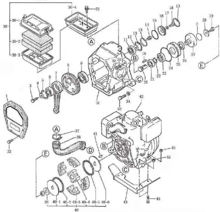
7.2 CRANKCASE AND ENGINE ASSY
CRANKCASE AND ENGINE ASSY(B)
THROTTLE
| PART NO. | DESCRIPTION | QTY |
| B01 | Back of crankcase | 1 |
| B02 | O-ring φ22.4*2.65 | 1 |
| B03 | Bolt 8*20H.SW | 1 |
| B04 | Washer φ8 | 1 |
| B05 | Stop ring R-52 | 1 |
| B06 | Bearing 6304 | 1 |
| B07 | Connecting rod | 1 |
| B08 | Gear wheel | 1 |
| B09 | Bearing 6207 | 1 |
| B10 | Crank case | 1 |
| B11 | Bearing 6204 | 2 |
| B12 | Washer φ8 | 1 |
| B13 | Stop ring φ47 | 3 |
| B14 | Bolt 8*20H.SW | 1 |
| B15 | O-ring φ43.7×1.8 | 1 |
| B16 | Bearing cover | 1 |
| B17 | Nut M8 | 1 |
| B18 | Bolt 6*10 T | 1 |
| B19 | Flat key5*20 | 1 |
| B20 | Pinion( for engines except Honda GX100) | 1 |
| B20 | Pinion( for Honda GX100) | 1 |
| B21 | Bearing 6204 | 2 |
| B22 | Stop ring S-35 | 1 |
| B23 | Bearing 6007Z | 1 |
| B24 | O-ring G-100 | 1 |
| B25 | Spacer | 1 |
| B26 | Oil seal TC-40528 | 1 |
| B27 | Clutch drum( for engines except Honda GX120) | 1 |
| B27 | Clutch drum( for Honda GX120) | 1 |
| Key5*5*19R | 1 | |
| B28 | Lock washer | 1 |
| B29 | Bolt 8*25H.SW | 1 |
| B30 | Air cleaner assy (Optional) | 1 |
| B31 | Bolt 8*25H.SW (Optional) | 4 |
| B32 | Nut M6*18 | 8 |
| B33 | Hex bolt M10*50 | 2 |
| B34 | Spring washer φ10 | 2 |
| B35 | Nylon nut M10 | 2 |
| B36 | Flatgasket φ10 | 2 |
| B37 | Hoop φ40 (Optional) | 1 |
| B38 | Svphon, air filter (Optional)( depends on engines) | 1 |
| B39 | Lock washer.clutch | 1 |
| B40 | Clutch assy C812E (depends on engines) | 1 |
| B41 | Woodruff Key (depends on engines) | 1 |
| B42 | Engine | 1 |
| B43 | Engine Plate (depends on engines) | 1 |
| B44 | Hex bolt M8*40 | 4 |
| B45 | Lock nut M8 | 4 |
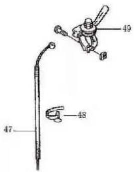
| B47 | Throttle cable (depends on engines) | 1 |
| B48 | Ribbon | 1 |
| B49 | Throttle lever | 1 |
7.3 TANK AND HANDLE ASSY
TANK AND HANDLE ASSY (C)
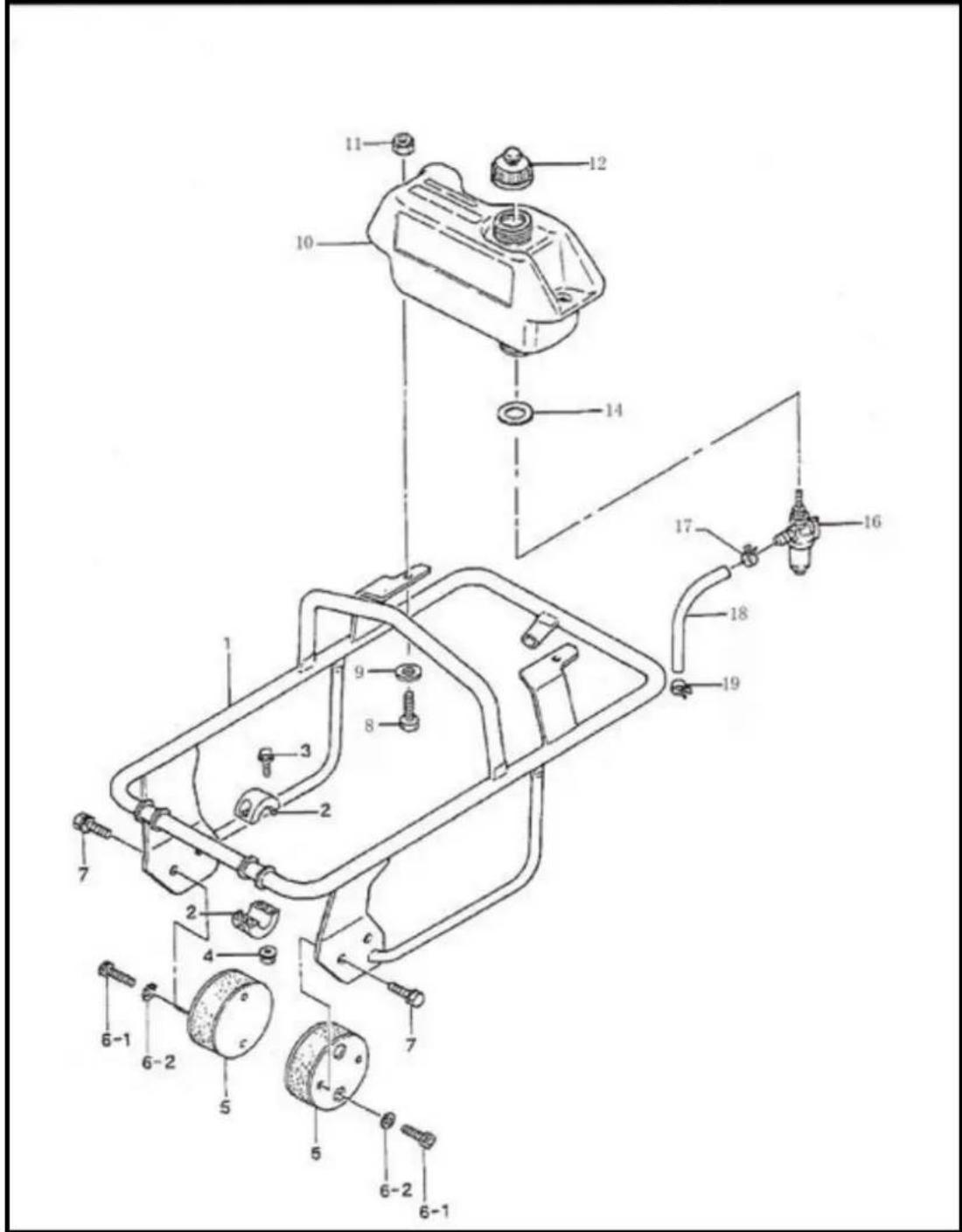
| PART NO. | DESCRIPTION | QTY |
| C01 | Handle( depends on engines) | 1 |
| C02 | Roller handle | 1 |
| C03 | Flange bolt 5*25 H | 4 |
| C04 | Flange nut | 4 |
| C05 | Shock absorber | 2 |
| C06-1 | Shock head bolt 10*20 T | 4 |
| C06-2 | Tooth locked washer φ10 | 8 |
| C07 | Bolt 8*30 T | 4 |
| C08 | Hex Bolt M8*20 | 2 |
| C09 | Gasket φ8 | 2 |
| C10 | Fuel tank | 1 |
| C11 | Nylon nut M8 | 2 |
| C12 | Cap assy, tank | 1 |
| C14 | washer, throttle lever | 1 |
| C16 | Fuel cock assy | 1 |
| C17 | Hose band 9.5D | 1 |
| C18 | Hose, fuel | 1 |
| C19 | Hose band 9.5D | 1 |
| Spring, clutch | 2 |