SP425-01 - Uncategorized KKT Kolbe - Free user manual and instructions
Find the device manual for free SP425-01 KKT Kolbe in PDF.

User questions about SP425-01 KKT Kolbe
0 question about this device. Answer the ones you know or ask your own.
Ask a new question about this device
Download the instructions for your Uncategorized in PDF format for free! Find your manual SP425-01 - KKT Kolbe and take your electronic device back in hand. On this page are published all the documents necessary for the use of your device. SP425-01 by KKT Kolbe.
USER MANUAL SP425-01 KKT Kolbe
INSTALLATION, OPERATION & MAINTENANCE MANUAL
KSTAR BluE-H5/H3 ENERGY STORAGE SYSTEM
KSTAR
Shenzhen Kstar New Energy Company Limited
Add: Kstar Industrial Park, Guangming Hi-Tech Park,
shenzhen,P.R.CHINA
Tel:0755-21389008 Fax:0755-21389008
Web:www.kstar.com
202011 IVer:1.0
Copyright Statement
This manual is under the copyright of Shenzhen Kstar Science and Technology Co., Ltd, with all rights reserved. Please keep the manual properly and operate in strict accordance with all safety and operating instructions in this manual. Please do not operate the system before reading through the manual.
KSTAR
Stock code:002518
CONTENTS
01 Introduction 01
1.1 System Introduction 01
1.2 Operating Model 02
1.2 Operation Modes 03
1.3 Safety Introduction 04
1.4 Battery Safety Datasheet 06
1.5 General Precautions 07
1.6 Part-time
1.6 Parts List 08
1.7 System Appearance 11
1.7 System Appearance 11
1.8 Liability Limitation 13
02 Installation 14
2.1 Installation Site and Environment 14
2.2 Installation 16
2.3 External CT connection 27
2.4 DRED port connections(optional) 27
2.5 Single Line Diagram 28
03 System Operation 30
3.1 Switch On 30
3.2 Switch Off 31
3.3 Emergency Procedure 31
04 EMS Introduction And Set UP 32
4.1 Function Description 32
4.2 Display and Setting 34
4.3 Setting 38
4.4 Inquiry 58
4.5 Statistics 59
4.6 Restart 61
05 Wireless Router Connection 62
5.1 Download APP 62
5.2 Connect Wi-Fi Datalogger 62
06 Create Account And Add Datalogger 63
6.1 Create Account 63
6.2 Add Datalogger 64
07 Routine Maintenance 65
7.1 Alarm code 65
7.2 Error code 66
08 Fault diagnosis and solutions 67
09 Machine Parameters 70
10 Routine Maintenance 75
11 Quality Assurance 76
12 Contact Information 77
01 Introduction
1.1 System Introduction
Kstar BluE-H5 (incl.BluE-PACK10.2 and BluE-S 5000D)/BluE-H3 (incl. BluE-PACK5.1 and BluE-S 3680D) can be applied in DC-coupled systems (mostly new installation), AC-coupled systems (mostly retrofit) and Hybrid-coupled systems (mostly retrofit, and PV capacity-increase), as the following schemes show:
| Solution | Configuration | |
| Inverter | ESS | |
| BluE H3-5 | BluE-S 3680D | BluE-PACK5.1 |
| BluE H3-10 | BluE-S 3680D | BluE-PACK10.2 |
| BluE H5-10 | BluE-S 5000D | BluE-PACK10.2 |
| BluE H5-20 | BluE-S 5000D | BluE-PACK20.4 |
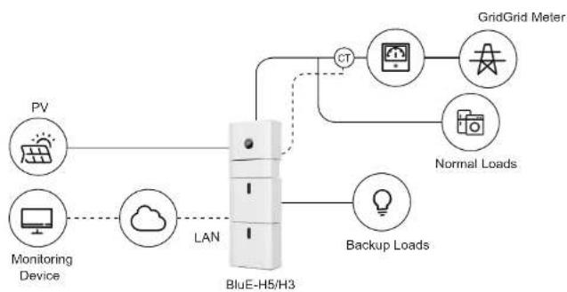
flowchart
graph TD
    PV["PV"] --> LAN["LAN"]
    Monitoring["Monitoring Device"] -.-> LAN
    LAN --> Backup["Backup Loads"]
    NAV["Cloud"] -.-> LAN
    LAN --> GridGridMeter["GridGrid Meter"]
    LAN --> NormalLoad["Normal Loads"]
    LAN --> CT["CT"]
    CT --> GridGridMeter
    Cloud --> NormalLoad
    NAV --> Backup
Figure1 DC-coupled Storage System – Scheme
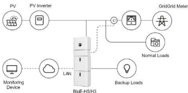
flowchart
graph TD
    A["PV"] --> B["PV Inverter"]
    B --> C["Grid Grid Meter"]
    D["Monitoring Device"] --> E["Cloud"]
    E --> F["LAN"]
    F --> G["Backup Loads"]
    G --> H["BluE-H5/H3"]
    H --> I["C"]
    I --> J["Grid Grid Meter"]
    H --> K["Light Bulb"]
Figure 2 AC-coupled Storage System – Scheme
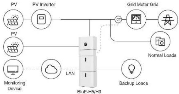
flowchart
graph TD
    PV["PV"] --> PVInverter["PV Inverter"]
    PV --> PVMonitoring["Monitoring Device"]
    PVInverter --> GridMeterGrid["Grid Meter Grid"]
    PVMonitoring --> LAN["LAN"]
    LAN --> BlueE-H5["H3"]
    BlueE-H5 --> BackupLoad["Backup Loads"]
    BlueE-H5 --> GridMeterGrid
    GridMeterGrid --> NormalLoad["Normal Loads"]
    GridMeterGrid --> Control["Control"]
    Control --> BlueE-H5
    BlueE-H5 --> MonitoringDevice["Monitoring Device"]
    MonitoringDevice --> Cloud["Cloud"]
    Cloud --> LAN
    Control --> GridMeterGrid
    Control --> NormalLoad
Figure 3 Hybrid-coupled Storage System – Scheme
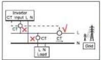
! CAUTION:
If CT test pass but inverter still can't achieve export power (power is not controllable or always 0 power output). Please check installation location of the CT.
KSTAR
User Manual User Manual
KSTAR
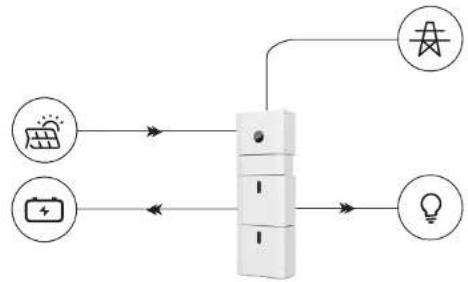
1.2 Operation Modes:
There are three basic modes that end users can choose via inverter screen/APP.
- SELF CONSUME: The energy generated by the solar panels will be used in the following order: Feed the home loads; Charge the battery and then, feed into the grid. When the sun is off, the load will be supported by battery to enhance self consumption. If the power supply from the batteries is not sufficient, the grid will support the load demand.
flowchart
graph TD
    A["太阳能电池图标"] --> B["中央设备"]
    C["电池图标"] --> B
    D["光伏电池图标"] --> B
    B --> E["灯泡图标"]
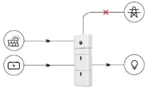
- BAT PRIORITY: Under this mode, the battery is only used as a backup power supply when the grid falls and as long as the grid works, the batteries won't be used to power the loads. The battery will get charged with the power generated by the PV system or from the grid.
flowchart
graph TD
    A["太阳能电池"] --> B["开关"]
    C["电池"] --> B
    D["LED"] --> B
    B --> E["灯泡图标"]
    B --> F["电源符号"]
    style B stroke:#000,stroke-width:2px
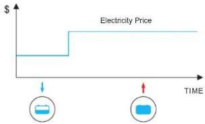
- PEAK SHIFT: This mode is designed for time-use mode customer. The customer is able to set up the charging/discharging time & power via inverter screen or APP.
line
| TIME | Electricity Price | | ---- | ----------------- | | 0 | $ | | >1 | $ |1.3 Safety Introduction
1.3.1 Manual Keeping
This manual contains important information about operating the system. Before operating, please read it very carefully.
The system should be operated in strict accordance with the instructions in the manual, otherwise it can cause damages or loss to equipment, personnel and property. This manual should be kept carefully for maintenance and reparation.
1.3.2 Operator Requirements
The operators should get a professional qualification, or be trained.
The operators should be familiar with the whole storage system, including compositions and working principles of the system.
The operators should be familiar with the Product Instruction.
While maintaining, the maintainer is not allowed to operate any equipment until all the equipment has been turned off and fully discharged.
1.3.3 Protection of Warning Sign
The warning signs contain important information for the system to operate safely, and it is strictly prohibited to torn or damage them. Ensure that the warning signs are always well-functioned and correct placed. The signs must be replaced immediately when damaged.
KSTAR
User Manual User Manual
KSTAR

This sign indicates a hazardous situation which, if not avoided, could result in death or serious injury!

The Storion BluE-H5/H3 must not be touched or put into service until 5 minutes after it has been switched off or disconnected to prevent an electric shock or injury.

This sign shows danger of hot surface!

Refer to the operating instructions.
1.3.4. Setting of Warning Sign for Safety
During instruction, maintenance and repair, follow the instructions below to prevent non-specialist personnel from causing misuse or accident:
- Obvious signs should be placed at front switch and rear-level switch to prevent accidents caused by false switching.
- Warning signs or tapes should be set near operating areas.
- The system must be reinstalled after maintenance or operation.
1.3.5 Measuring Equipment
To ensure the electrical parameters to match requirements, related measuring equipment are required when the system is being connected or tested. Ensure that the connection and use matched specification to prevent electric arcs or shocks.
1.3.6 Moisture Protection
It is very likely that moisture may cause damages to the system. Repair or maintaining activities in wet weather should be avoided or limited.
1.3.7 Operation After Power Failure
The battery system is part of the energy storage system which stores life-threatening high voltage even when the DC side is switched off. Touching the battery outlets is strictly prohibited. The inverter can keep a life-threatening voltage even after disconnecting it from the DC and / or AC side. Therefore, for safety reasons, it must be tested with a properly calibrated voltage tester before an installer works on the equipment.
1.4 Battery Safety Datasheet
1.4.1 Hazard Information
Classification of the hazardous chemical
Exempt from classification according to Australian WHS regulations.
Other hazards
This product is a Lithium Iron Phosphate Battery with certified compliance under the UN Recommendations on Transport of Dangerous Goods, Manual of Tests and Criteria, Part III, subsection 38.3. For the battery cell, chemical materials are stored in a hermetically sealed metal case, designed to withstand temperatures and pressures encountered during normal use. As a result, during normal use, there is no physical danger of ignition or explosion and chemical danger of hazardous materials' leakage. However, if the product is exposed to a fire, added mechanical shocks, decomposed, added electric stress by misuse, the gas release vent will be operated. The battery cell case will be breached at the extreme. Hazardous materials may be released. Moreover, if heated strongly by the surrounding fire, acrid or harmful fume may be emitted.
1.4.2 Safety Datasheet
For detailed information please refer to the provided battery safety datasheet.
1.5 General Precautions

DANGER
Danger to life due to high voltages of the PV array, battery and electric shock. When exposed to sunlight, the PV array generates dangerous DC voltage which will be present in the DC conductors and the live components of the inverter. Touching the DC conductors or the live components can lead to lethal electric shocks. If you disconnect the DC connectors from the system under load, an electric arc may occur leading to electric shock and burns.
- Do not touch uninsulated cable ends.
◆ Do not touch the DC conductors.
◆ Do not open the inverter and battery.
◆ Do not wipe the system with damp cloth. - Have the system installed and commissioned by qualified people with the appropriate skills only.
- Prior to performing any work on the inverter or the battery pack, disconnect the
inverter from all voltage sources as described in this document.

WARNING
Risk of chemical burns from electrolyte or toxic gases. During standard operation, no electrolyte shall leak from the battery pack and no toxic gases shall form. Despite careful construction, if the Battery Pack is damaged or a fault occurs, it is possible that electrolyte may be leaked or toxic gases formed.
Do not install the system in any environment of temperature below -10^ or over 50^ and in which humidity is over 90% .
◆ Do not touch the system with wet hands.
- Do not put any heavy objects on top of the system.
◆ Do not damage the system with sharp objects.
- Do not install or operate the system in potentially explosive atmospheres or areas of high humidity.
- Do not mount the inverter and the battery pack in areas containing highly flammable materials or gases.
- If moisture has penetrated the system (e.g. due to a damaged enclosure), do not install or operate the system.
- Do not move the system when it is already connected with battery modules. Secure the system to prevent tipping with restraining straps in your vehicle.
◆ The transportation of Kstar BluE-H5/H3 must be made by the manufacturer or an instructed personal. These instructions shall be recorded and repeated.
◆ A certified ABC fire extinguisher with minimum capacity of 2kg must be carried along when transporting.
It is totally prohibited to smoke in the vehicle as well as close to the vehicle when loading and unloading.
For the exchange of a battery module, please request for new hazardous goods packaging if needed, pack it and let it be picked up by the suppliers.
In case of contact with electrolyte, rinse the affected areas immediately with water and consult a doctor without delay.

CAUTION:
Risk of injury through lifting or dropping the system. The inverter and battery are heavy. There is risk of injury if the inverter or battery is lifted incorrectly or dropped during transport or when attaching to or removing from the wall.
- Lifting and transporting the inverter and battery must be carried out by more than 2 people.
1.6 Parts List
Check the following parts list to ensure it is complete.
Kstar delivers a total system separately on site to client, this consists of:
 |  | |||
| 4xM5*12 | 2xφ8*60 | 1xCT Connector | 1xCT andcom cable | 2xAC Collector |
 |  |  | ||
| 2xMC4 | 1xCollector | 1x Mounting Panel | 1xUser Manual | |
KSTAR
User Manual User Manual
KSTAR
| BluE-PACK5.1 | ||
 | ### | ### |
| 4xφ8*60 | 4xM6 Gasket2xM5*12 | |
| ### | ||
| 1x Mounting Panel | ||
| BluE-PACK10.2 (includ two pieces BluE-PACK5.1) | ||
| [244H] | [3682] | [7276] |
| 8xφ8*60 | 4xM5*12 | 2xMounting Panel |
 | [224D] | [6HTT] |
| 8xM6 Gasket | 2xPower Cable(1 black, 1 red) | 1x Battery Communication Cable |
 |  |  | |
| 12xφ8*60 | 6x M5*12 | 3x Mounting Panel | |
| [6ZSC] |  | 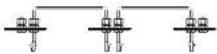 | |
| 12xM6 Gasket | 4xPower Cable(2 black, 2 red) | 1x Battery Communication Cable | |
| [0087] | 2x19 | 2x19 | |
| 16xφ8*60 | 8xM5*12 | 4xMounting Panel | |
| (aest) | 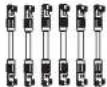 | (best) | |
| 16x M6 Gasket | 6x Power Cable(3 black, 3 red) | 1xBattery Communication Cable | |
1.7 System Appearance
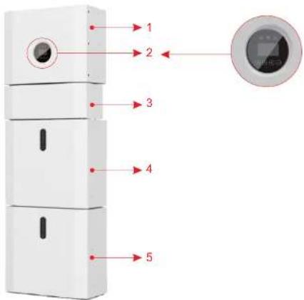
Figure 4 BluE-H5/H3 Delivery Scope
| Object | Description |
| 1 | Hybrid Inverter BluE-S 5000D/3680D |
| 2 | EMS Display Screen |
| 3 | Cable Box (connected to Inverter) |
| 4 | BluE-PACK5.1 (Battery 1) |
| 5 | BluE-PACK5.1 (Battery 2, if configured) |
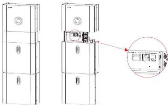
1.7.1 Cable Box Part
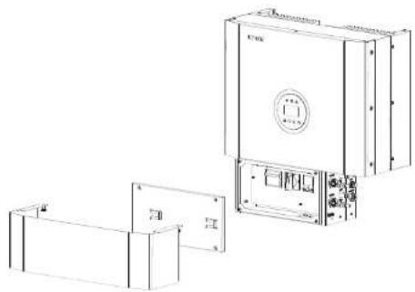
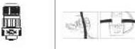
natural_image
Technical line drawing of a mechanical device with front panel and side panels (no text or symbols)Figure 5 Inverter without Cable Box Covers—Front View
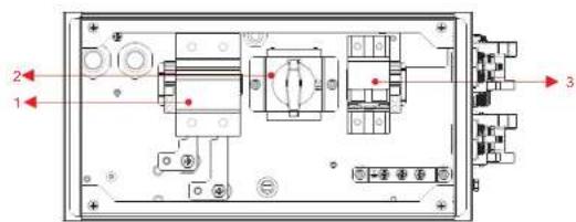
Figure 6 Cable Box Part without Covers – Front View
| Object | Description |
| 1 | Battery circuit breaker |
| 2 | DC isolation switch |
| 3 | Output terminal block ( BACK UP/ON GRID ) |
KSTAR
User Manual User Manual
KSTAR
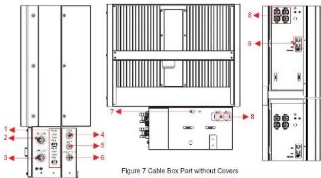
| Object Object | Description | DVC class | Description | DVC class | |
| 1 | PV1, PV2 | DVC C | 2 | GRID | DVC C |
| 3 | BACKUP | DVC C DVC A | 4 | DRM | |
| 5 | COM | DVC A DVC A | 6 | CT/METER | |
| 7 | INV | DVC C | 8 | BAT+,BAT- | DVC C |
| 9 | RJ45 | DVC C |
1.8 Liability Limitation
Any product damage or properly loss caused by the following conditions, Kstar does not assume any direct or indirect liability.
- Product modified, design changed or parts replaced without authorization; Kstar
- Changes, repair attempts and erasing of series number or seals by non Kstar technician;
- System design and installation are not in compliance with standards and regulations;
- Fail to comply with the local safety regulations (VDE for DE, SAA for AU);
- Transport damage (including painting scratch caused by rubbing inside packaging during shipping). A claim should be made directly to shipping or insurance company in this case as soon as the container/packaging is unloaded and such damage is identified;
- Fail to follow any/all of the user manual, the installation guide and the maintenance regulations;
- Improper use or misuse of the device;
• Insufficient ventilation of the device;
- The maintenance procedures relating to the product have not been followed to an acceptable standard;
- Force majeure (violent or stormy weather, lightning, overvoltage, fire etc.);
• Damages caused by any external factors.
13 www.kstar.com
02 Installation
This Manual introduces the basic steps to install and set up Kstar BluE-H5/H3.

Please be cautious unpacking the battery, otherwise components could be damaged.
2.1 Installation Site and Environment
2.1.1 General
This BluE-H5/H3 energy storage system is outdoor version and can be installed in an outdoor or an indoor location.
When BluE-H5/H3 systems are installed in a room, BluE-H5/H3 must not be hampered by the structure of the building, the furnishings and equipment of the room.
The Storion BluE-H5/H3 is naturally ventilated. The location should therefore be clean, dry and adequately ventilated. The mounting location must allow free access to the unit for installation and maintenance purposes, and the system panels must not be blocked.
The following locations are not allowed for installation:
- habitable rooms;
• ceiling cavities or wall cavities;
- on roofs that are not specifically considered suitable;
- access / exit areas or under stairs / access walkways;
- where the freezing point can be reached, such as garages, carports or other places as well as wet rooms (environmental category 2);
- locations with humidity and condensation over 90% ;
- places where salty and humid air can penetrate;
• seismic areas - additional security measures are required;
- Sites with altitude below 2000m;
- places with an explosive atmosphere;
- locations with direct sunlight or a large change in the ambient temperature;
- places with flammable materials or gases or an explosive atmosphere.
2.1.2 Restricted Locations
The BluE-H5/H3 shall not be installed :
(a) in restricted locations as defined for panels in AS / NZS 3000;
(b) within 600mm of any heat source, such as hot water unit, gas heater, air conditioning unit or any other appliance.
(c) within 600mm of any exit;
(d) within 600mm of any window or ventilation opening;
(e) within 900mm of access to 240Vac connections;
(f) within 600mm of side of other device.
KSTAR
User Manual User Manual
KSTAR
A BluE-H5/H3 installed in any corridor, hallway, lobby or the like and leading to an emergency exit shall ensure sufficient clearance for safe egress of at least 1 meter.
The BluE-H5/H3 must also not be installed in potentially explosive atmospheres for gas cylinders that are heavier than air gases and have a vent clamp in accordance with AS/NZS 3000.
2.1.3 Barrier to Habitable Rooms
To protect against the spread of fire in living spaces where the BluE-H5/H3 is mounted or on surfaces of a wall or structure in living spaces with a BluE-H5/H3 on the other side, the wall or structure shall have a suitable non-combustible barrier. If the mounting surface itself is not made of a suitable non-combustible material, a non-combustible barrier can be placed between the BluE-H5/H3 and the surface of a wall or structure.
If the BluE-H5/H3 is mounted at a wall or at a distance of 300mm from the wall or the structure separating it from the habitable space, the distances to other structures or objects must be increased. The following distances must remain free:
(i) 600 mm beside the BluE-H5/H3;
(ii) 500 mm above the BluE-H5/H3;
(iii) 600 mm before the BluE-H5/H3.
If the distance between the BluE-H5/H3 and the ceiling or any object above the system is less than 500mm, the ceiling or structural surface above the system must be made of noncombustible material within a radius of 600mm around the system.
The BluE-H5/H3 must be mounted to ensure the highest point is not more than 2.2m above the ground or the platform.
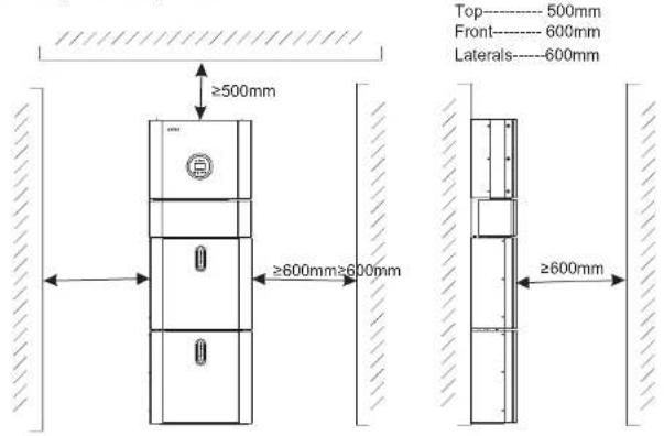
Figure 8 Limited Distance of Installation to Neighboring Objects
15 www.kstar.com
2.2 Installation
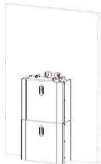
Step 1 Remove the battery and inverter from the packaging box.
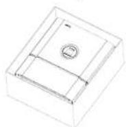
Figure 9 Unpacking the inverter and battery
2.2.1 Battery Installation
Step 2 Assemble the battery mounting panel on the battery.

Figure 10 Assemble Battery Mounting Panel
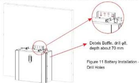
Step 3 Position the battery parallel to the wall and use a 8mm drill to drill holes at a depth of about 70mm in the wall for sub sequent fixation of the mounting plates.
www.kstar.com
KSTAR
User Manual User Manual
KSTAR
NOTE:
The type B RCD must be installed on the backup port of the system. In addition, the installation of inverter must fulfill AS/NZS 3000, AS/NZS 4777.1 and AS/NZS 5033. the internal N line of converter is connected to grid neutral via internal relays, when in stand-alone mode.
Step 4 Remove the debris baffle and secure the battery to the wall with screws and gaskets.
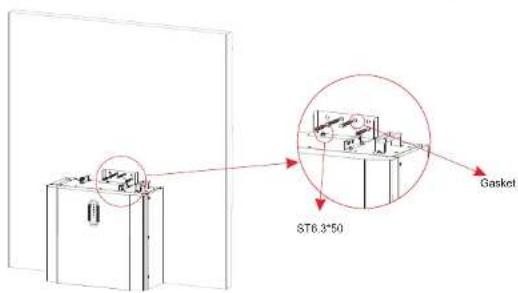
Figure 12 Battery Installation – Mounting on the Wall
Step 5 To assemble the second (and all other) battery, repeat steps 6 and 7, respectively.
natural_image
Line drawing of a two-tier refrigerator with top shelf (no text or symbols)Figure 13 Battery Installation – Second Battery Installation
17 www.kstar.com
2.2.2 Inverter Installation
Step 6 Inverter Installation.
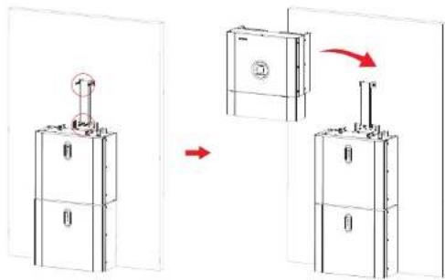
Figure 14 Inverter Installation
Step 7 Hang the inverter onto the mounting panels, adjust the entire system and ensure that the battery and the inverter have been securely hung onto the panels and brackets.
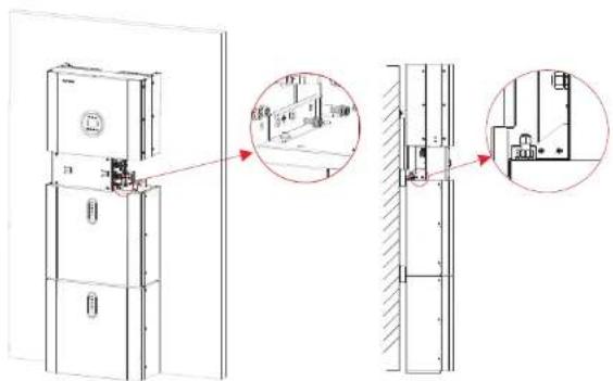
Figure 15 Inverter Installation on the Wall
KSTAR
User Manual User Manual
KSTAR
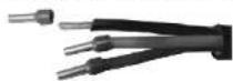
Step 8 Please make AC cables on site.
Step 8-1 Please follow the AC cable requirements below.
For all AC connections, 4-10mm² 105 XJ cable is required to be used. Please make sure the resistance of cable is lower than 1 ohm. If the wire is longer than 20m, it's recommended to use 10mm² cable.

WARNING:
There are "L" "N" "÷" symbols marked inside the connector, the Line wire of grid must be connected to "L" terminal; the Neutral wire of grid must be connected to "N" terminal; the Earth of grid must be connected to "÷"
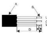
| Object | Description | Value |
| A | External diameter | 12mm to 18mm |
| B | Copper conductor cross-section | 4mm2 to 10mm2 |
| C | Stripping length of the insulated conductors | approx.13mm |
| D | Stripping length of the outer sheath of the AC cable | approx.53mm |
| The PE conductor must be 10mm longer than the L and N conductors | ||
b. Insert the conductor into the suitable ferrule acc. to DIN 46228-4 and crimp the contact.
b
c. Unscrew the swivel nut from the threaded sleeve and thread the swivel nut and threaded sleeve over the AC cable.
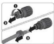
C
d. Insert the crimped conductors L, N and PE into the corresponding terminals and tighten the screw with a hex key wrench screwdriver(size:2.5, 1.2-2.0N.m). Ensure that all conductors are securely in place in the screw terminals on the bush insert.
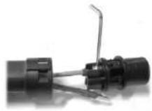
d
e. Screw the swivel nut onto the threaded sleeve. This seals the AC connector and provides strain relief for the AC cable. When doing so, hold the bush insert firmly by the locking cap. This ensures that the swivel nut can be screwed firmly onto the threaded sleeve.
e
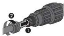
- Assembly the plug shell, adapter as below picture, Push the adapter and Shell by hand until a "Click" is heard or felt.
f
g. Plug the AC connector into the jack for the AC connection by hand until a "Click" is heard or felt.
KSTAR
User Manual User Manual
KSTAR
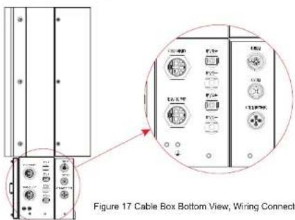
(8) Use tool to clamp the AC wiring terminal and wire rod; screw the nut, but do not tighten it. Make sure that the cable is free to pass through the waterproof components. Once the terminal is connected to the right site of the inverter, tighten the nut.
natural_image
Pure technical line drawing of a three-tiered electrical cabinet or enclosure with no text, numbers, or symbols.Figure 16
(9) Connect the AC wiring terminal to the corresponding hole site of the inverter and lock it with a screw driver or electric screw driver (suggestion: stem diameters and torsion of screwdriver or electric screwdriver should be 4mm and 8\~12kg-f.cm respectively)
(10) Tighten the nut.
(11) Circuit breaker parameters are recommended:
Back-up 32A/400Vac 6KA
On-grid 40A/400Vac 6KA
Step 8-2 Connect the Backup and Grid cables in advance according to the connector mode, and connect them to the Backup and Grid board connectors in turn.
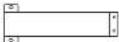
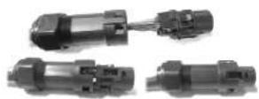
Step 9 Take out the communication cable set provided in the accessory parts of one BluE-H5/H3-BAT, cut off one end and crimp a new RJ45 connector. If there are two batteries, you only need to remake one of battery communication cable on site.
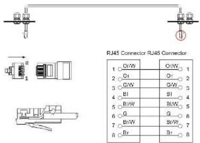
Figure 18 Network Cable Type B

NOTE:
The communication cable is in type B, see Figure 18. Leave the power cables and communication cables hanging on outside. Leave the device aside.
KSTAR
User Manual User Manual
KSTAR
Step10 Connect the BAT communication cable of the cable box from Step 13 to the topmost battery at the right side. Then use the communication cable supplied with the batteries to connect the batteries to each other via the respective connectors on the left side. After you have connected all the modules together, close all covers (if you want to connect further battery modules, you must mount them before closing).
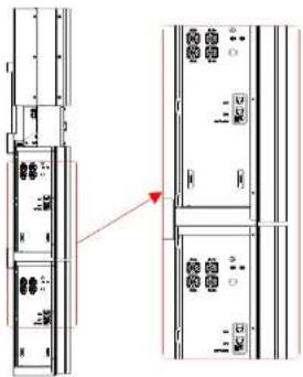
natural_image
Technical line drawing of a multi-chamber electrical cabinet with no visible text or symbolsFigure 19 Wiring the Communication Cable
Step11 Connect the power cables of the bottom battery from Step 4 to the side terminals of the top battery. Make sure that red connects to red and black connects to black.
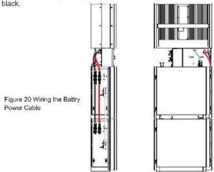
23 www.kstar.com
Step12 Close the lid and tighten the screw.
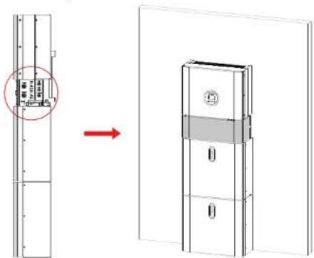
Figure 21
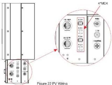
Step13 Close the battery covers and connect the PV-MC4 connectors to the system (connection on both sides). Also, connect all AC cables, the meter communications cable METER, and the Ethernet cable LAN. Then close the cable box cover. The installation is now complete.
www.kstar.com
KSTAR
User Manual User Manual
KSTAR
Step14 Open the front cover of the last battery and remove the DIP cover. Now set the DIP switch 2 to "on" mode and close the cover again.
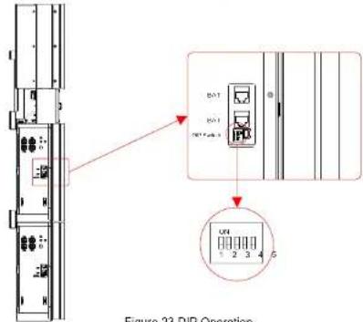
Figure 23 DIP Operation
DIP switch setting
When PACKs are used in parallel, the address can be distinguished by setting the address on the BMS DIP switch. It is necessary to avoid setting the address to the same. For the definition of the BMS DIP switch, refer to the following table.

NOTE:
The address of the battery pack connected to the inverter is 1, and the others are dialed in the order of 2-8.
| address | DIP switch position □ | |||
| □ | #1□ | #2 □ | #3□ | #4□ |
| 1 | ON | OFF | OFF OFF | |
| 2 | OFF | ON | OFF OFF | |
| 3 | ON | ON | OFF OFF | |
| 4 | OFF | OFF | ON OFF | |
| 5 | ON | OFF | ON OFF | |
| 6 | OFF | ON | ON OFF | |
| 7 | ON | ON | ON OFF | |
| 8 OFF | OFF OFF ON | |||


NOTE:
The DIP setting is only changed on the last battery.
If you connect more than 2 battery modules to the system, please only install the additional batteries 3-4 on the side of the system. You can connect up to 4 batteries, 2 each mounted on top of each other, to the BluE-H5/H3. To do this, carry out the individual installation steps as for the first two batteries, including the DIP setting on the last module.
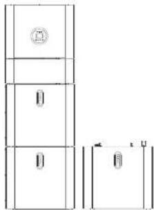
Figure 24 Increase the Battery Modules

NOTE:
Recommended AC circuit breaker rating is 32A.

NOTE:
It is necessary to disconnect the power line, communication line and communication line between battery pack and inverter to manually sleep all battery packs.

STATEMENT:
The method of anti-islanding protection is Method(c)
2.3 External CT connection
The electricity meter should be mounted and connected at the grid transition point (feed-in point) so that it can measure the grid reference and feed-in power.
- Loosen the nut, and untangle the single-aperture sealing ring.
| Pin Pin | Description | Description | |
| 1 | CT positive electrode | 3 | NC |
| 2 | CT negative pole | 4 | NC |


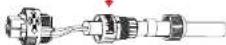
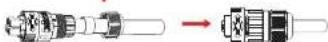
Figure 25
- Install the waterproof component and screw on the waterproof sheath nut.
- Open the external CT wiring port, the arrow points to the direction of the power grid, put the wire into the external CT card slot, and buckle the buckle.
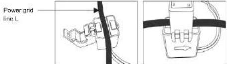

NOTE: External CT should be placed near the power grid.
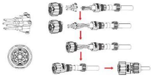
2.4 DRED port connections(optional)
DRED means demand response enable device. The AS/NZS 4777.2:2015 required inverter need to support demand response mode(DRM). This function is for inverter that comply with AS/NZS 4777.2:2015 standard. KSG single phase inverter is fully comply with all DRM. A 6P terminal is used for DRM connection.
| Pin | Description Description | Pin | |
| 1 | DRM 1/5 | 4 | DRM 4/8 |
| 2 | DRM 2/6 | 5 | RefGen |
| 3 | DRM 3/7 | 6 | Com/DRMO |
Please follow below figure to assemble DRM connector.
flowchart
graph TD
    A["Pin 1"] --> B["Switch"]
    B --> C["Coil"]
    C --> D["Coil"]
    D --> E["Terminal"]

    subgraph Initial Assembly
        F["Pin 1"] --> G["Switch"]
        G --> H["Coil"]
        H --> I["Coil"]
        I --> J["Terminal"]

    end

    subgraph Final Assembly
        K["Switch"] --> L["Coil"]
        L --> M["Coil"]
        M --> N["Terminal"]
    end
Figure 26 DRM connector
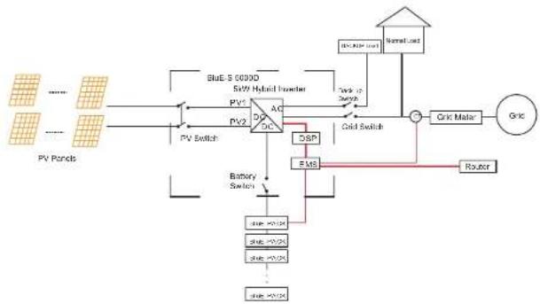
2.5 Single Line Diagram
The single line diagrams of DC-, AC- and Hybrid-coupled sysyem are as below:
flowchart
graph TD
    A["PV Panels"] --> B["Power Source"]
    B --> C["PV Switch"]
    C --> D["Grid Switch"]
    D --> E["Grid"]
    E --> F["Motor Load"]
    F --> G["Grid"]
    G --> H["Circuit Maker"]
    H --> I["Router"]
    I --> J["FSM"]
    J --> K["DSR"]
    K --> L["Battery Switch"]
    L --> M["Sub-DC"]
    M --> N["Sub-DC"]
    N --> O["Sub-DC"]
    O --> P["Sub-DC"]
    P --> Q["Sub-DC"]
    Q --> R["Sub-DC"]
    R --> S["Sub-DC"]
    S --> T["Sub-DC"]
    T --> U["Sub-DC"]
    U --> V["Sub-DC"]
    V --> W["Sub-DC"]
    W --> X["Sub-DC"]
    X --> Y["Sub-DC"]
    Y --> Z["Sub-DC"]
    Z --> AA["Sub-DC"]
    AA --> AB["Sub-DC"]
    AB --> AC["Sub-DC"]
    AC --> AD["Sub-DC"]
    AD --> AE["Sub-DC"]
    AE --> AF["Sub-DC"]
    AF --> AG["Sub-DC"]
    AG --> AH["Sub-DC"]
    AH --> AI["Sub-DC"]
    AI --> AJ["Sub-DC"]
    AJ --> AK["Sub-DC"]
    AK --> AL["Sub-DC"]
    AL --> AM["Sub-DC"]
    AM --> AN["Sub-DC"]
    AN --> AO["Sub-DC"]
    AO --> AP["Sub-DC"]
    AP --> AQ["Sub-DC"]
    AQ --> AR["Sub-DC"]
    AR --> AS["Sub-DC"]
    AS --> AT["Sub-DC"]
    AT --> AU["Sub-DC"]
    AU --> AV["Sub-DC"]
    AV --> AW["Sub-DC"]
    AW --> AX["Sub-DC"]
    AX --> AY["Sub-DC"]
    AY --> AZ["Sub-DC"]
    AZ --> BA["Sub-DC"]
    BA --> BB["Sub-DC"]
    BB --> BC["Sub-DC"]
    BC --> BD["Sub-DC"]
    BD --> BE["Sub-DC"]
    BE --> BF["Sub-DC"]
    BF --> BG["Sub-DC"]
    BG --> BH["Sub-DC"]
    BH --> BI["Sub-DC"]
    BI --> BJ["Sub-DC"]
    BJ --> BK["Sub-DC"]
    BK --> BL["Sub-DC"]
    BL --> BM["Sub-DC"]
    BM --> BN["Sub-DC"]
    BN --> BO["Sub-DC"]
    BO --> BP["Sub-DC"]
    BP --> BQ["Sub-DC"]
    BQ --> BR["Sub-DC"]
    BR --> BS["Sub-DC"]
    BS --> BT["Sub-DC"]
    BT --> BU["Sub-DC"]
    BU --> BV["Sub-DC"]
    BV --> BW["Sub-DC"]
    BW --> BX["Sub-DC"]
    BX --> BY["Sub-DC"]
    BY --> BZ["Sub-DC"]
Figure 27 DC-coupled system
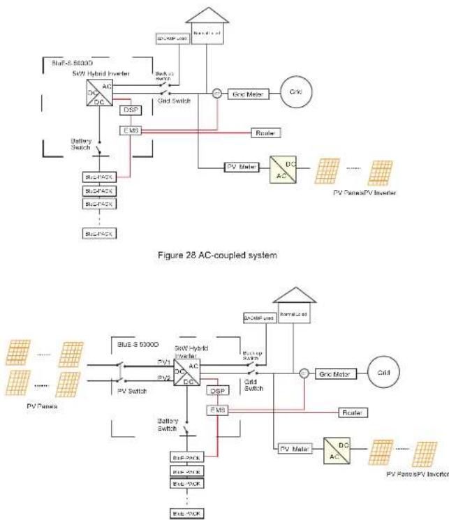
Figure 29 Hybrid-coupled system
03
System Operation
3.1 Switch On
When turning on the system, it is very important to follow the steps below to prevent damage to the system.
WARNING: Please check the installation again before turning on the system.
natural_image
Technical line drawing of a refrigerator with an inset close-up showing internal components (no text or symbols)Step 1:
Turn on the external PV switch.
Step 2
Turn on the external grid switch.
Step 3:
If backup load is applied, turn on the external Backup switch.

NOTE:
the Backup switch is only used when a backup load is applied.
Step 4
Open the outer shell of the cable box. Open the battery switch cover and turn on tery switch on the cable box.
Step 5:
Press power button on all the batteries until the indicator lights turn on.
Step 6
Close the battery switch cover and the outer shell of the cable box.
3.2 Switch Off
Step 1: Press the power button on all the batteries, till the lights turn off.
Step 2: Open cable box outer shell, open the battery switch cover and turn off the battery switch.
Step 3: Turn off the external grid switch.
Step 4: If backup load is applied, turn off the external backup switch.
Step 5: Turn off the external PV switch on the cable box.
Step 6: Close the battery switch cover and the outer shell of cable box.
3.3 Emergency Procedure
When the BluE-H5/H3 energy storage system appears to be running abnormally, you can turn off the grid-connected main switch that directly feeding the BESS, and turn off all load switches within the BESS, turn off the battery switch at the same time. To prevent a potentially fatal personal injury, if you want to repair or open the machine after the power is switched off, please measure the voltage at the input terminals with a suitably calibrated voltage tester. Before working on this equipment, please confirm that there is no grid electric supply to the BESS! The upper cover plate cannot be opened until the DC-link capacitance inside the battery modules discharges completely about 15 minutes later.
3.3.1 Emergency Handling Plan
-
Disconnect the AC breaker.
-
Check the control power supply. If it is OK, return the power supply to find out the reason.
-
Please record every detail related to the fault, so Kstar can analyse and solve the fault. Any operation of equipment during a fault is strictly forbidden, please contact Kstar as soon as possible.
-
As battery cells contain a little Oxygen inside and all cells have got explosion-proof valves, explosion hardly happens.
-
When the indicator light on the battery shows a red fault, check the fault type through the communication protocol, and contact our after-sales service personnel for advice.
3.3.2 Hazards
If the battery pack leaks electrolyte, avoid contact with the leaking liquid or gas. If one is exposed to the leaked substance, immediately perform the actions described below:
Inhalation: Evacuate the contaminated area, and seek medical attention.
Eye contact: Rinse eyes with running water for 5 minutes, and seek medical attention.
Contact with skin: Wash the affected area thoroughly with soap and water, and seek medical attention.
Ingestion: Induce vomiting and seek medical attention.
■ 31 www.kstar.com
3.3.3 Fire
If a fire breaks out in the place where the battery pack is installed, perform the following countermeasures:
Fire extinguishing media
During normal operation, no respirator is required. Burning batteries can not be extinguished with a regular fire extinguisher, this requires special fire extinguishers such as the Novec 1230, the FM-200 or a dioxin extinguisher. If the fire is not from a battery, normal ABC fire extinguishers can be used for extinguishing.
Fire -fighting instructions
- If fire occurs when charging batteries, if it is safe to do so, disconnect the battery pack circuit breaker to shut off the power to charge.
- If the battery pack is not on fire yet, extinguish the fire before the battery pack catches fire.
- If the battery pack is on fire, do not try to extinguish but evacuate people immediately.

There may be a possible explosion when batteries are heated above 150^ C. When the battery pack is burning, it leaks poisonous gases. Do not approach.
Effective ways to deal with accidents
Battery in dry environment: Place damaged battery into a segregated place and call local fire department or service engineer.
Battery in wet environment: Stay out of the water and don't touch anything if any part of the battery, inverter, or wiring is submerged.
Do not use a submerged battery again and contact the service engineer.
04 Ems Introduction And Set Up
4.1 Function Description
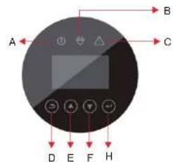
Figure 30 BluE-H5/H3 EMS Interface
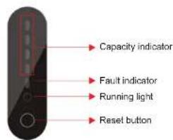
Figure 31 BluE-PACK Interface
www.kstar.com
32
KSTAR
User Manual
| Object | Name | Description |
| A | Indicator LED | Grid connection |
| B | Off-grid | |
| C | Red: The inverter is in fault. | |
| D | Button Function | Return Button: Escape from current interface or function. |
| E | Up button: Move cursor to upside or increase value. | |
| F | Down Button: Move cursor to downside or decrease value. | |
| H | ENT Button: Confirm the selection. |
LED indicator description
Table 4.1 LED working status indication
| status | Normal/Alarm /Protection | ON/OFF | RUN | ALM | Power indicator LED | Instructions | |||||
| ● | ● | ● | ● | ● | ● | ● | ● | ||||
| Shut down | domancy | off | off | off | off | off | off | off | off | off | ALL OFF |
| Standby | Normal | light | Flash one time | off | According to battery indicator | standby mode | |||||
| Alarm | light | Flash one time | three times | Module low voltage | |||||||
| charge | Normal | light | light | off | According to battery indicator(Power indicator highest LED flashes two) | The maximum powerLED flashes twice, and the ALM does not flash when an overcharge alarm occurs | |||||
| Alarm | light | light | Flash three times | ||||||||
| Overcharge protection | light | light | off | light | light | light | light | light | light | If there is no mains electricity, the indicator light turns to standby | |
| Temperature,overcurrent,failure,protection | light | off | light | off | off | off | off | off | off | Stop charging | |
| Discharge | Normal | light | RMS time | off | According to battery indicator | ||||||
| Alarm | light | Depr Time | Fur Time | ||||||||
| Undervoltage protection | light | off | off | off | off | off | off | off | off | Stop discharging | |
| Temperature,overcurrent,short circuit,reverse connection,failure protection | light | off | light | off | off | off | off | off | off | Stop discharging | |
| Failure | off | off | light | off | off | off | off | off | off | Stop charging and discharging | |
User Manual
KSTAR
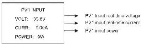
4.2. Display and Setting
4.2.1 PV1 input display interface
Interface
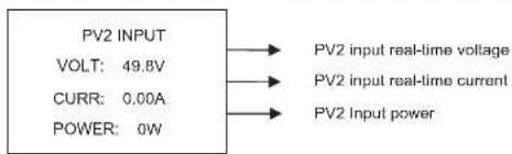
4.2.2 PV2 input display interface
Interface
4.2.3 Bus voltage
Interface

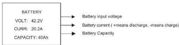
4.2.4 Battery
Interface
flowchart
graph LR
    A["BATTERY"] --> B["Battery input voltage"]
    A --> C["Battery current (+means discharge, -means charge)"]
    A --> D["Battery Capacity"]
    A --> E["VOLT: 42.2V"]
    A --> F["CURR: 20.2A"]
    A --> G["CAPACITY: 40Ah"]
KSTAR
User Manual
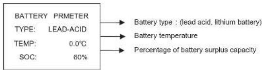
4.2.5 Battery Prmeter
Interface
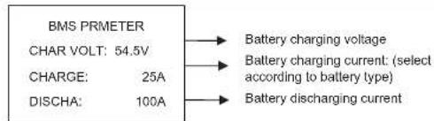
4.2.6 BMS parameters
Interface
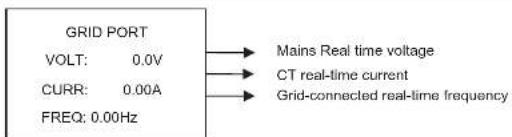
4.2.7 Grid-connected output
Interface
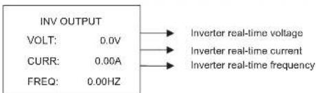
4.2.8 Inverter output
Interface
35 www.kstar.com
User Manual
KSTAR
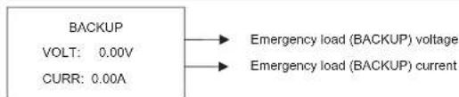
4.2.9 Load
Interface
4.2.10 Power
Interface
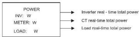
flowchart
graph LR
    A["POWER"] --> B["INverter real - time total power"]
    C["INV: W"] --> D["CT real-time total power"]
    E["METER: W"] --> F["Load real-time total power"]
    G["LOAD: W"] --> H["Load real-time total power"]
4.2.11 Power
Interface
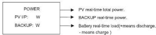
flowchart
graph LR
    A["POWER"] --> B["PV real-time total power."]
    C["PV I/P: W"] --> D["BACKUP real-time power."]
    E["BACKUP: W"] --> F["Battery real-time load(+means discharge, - means charge .)"]
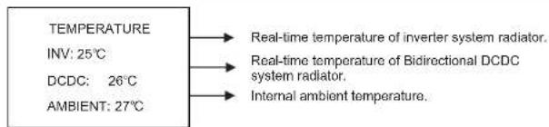
4.2.12 Temperature
Interface
KSTAR
User Manual User Manual
KSTAR
4.2.13 Status information
Interface
Description
STATE
SYS: ERROR
INV: STANDBY
DCDC: STANDBY
System information: Power-up mode, standby
mode, hybrid grid-connection, off-grid operation,
mains charging mode, PV charging mode, bypass
mode, fault mode, DSP programming, ARM
programming.
INV: standby mode, off-grid inverter mode, grid-
connected mode, and transition of grid-connection
to off-grid, transition of off-grid to grid mode.
DCDC: standby mode, soft start mode, charging mode.
4.2.14 Error information
Interface
ERROR NO.
WARNING: W11-1
FAULT:
F10-1
Alarm code (see Chapter 9)
Error code (see Chapter 9)
4.2.15 System setting
Interface
Description
SYSTEM
STATE: PEAKS HIFT
GRID STD:
China
PV I/P: INDEPN
Status mode: Self-generation and self-
consumption, Peak load shifting, and Battery
priority.
Grid-connection standards: China, Germany,
Australia, Italy, Spain, UK, Hungary, Belgium,
Western Australia, Greece, France, Bangkok,
Thailand, local and 60HZ.
PV Input mode: independent connection, parallel
connection, constant voltage.
Press ESC button to enter user setting
4.2.16 User setting
Interface
Description
-USER-
→1:SETUP
2:INQUIRE
3:STATISTIC
Press ESC on the Main Display Interface to enter
the user interface.
See chapter 8.2 for more setting details.
Enter the password before setting up the user.
Interface Description
-PASSWORD-
INPUT: XXXXX
After entering the setup interface, the system will prompt to input password:
The default password is "000000", which can be altered in Password setting menu;
Press UP/DOWN button to increase or decrease
the figure that is input;
Press ENTER button to move the cursor
backwards or confirm the setting;
Press ESC button to move the cursor forward.
4.3 Setting
Interface
Description
-SETUP--
+1:SYS SETTING
2:BAT SETTING
3:GRID STD
4:RUN SETTING
5:485 ADDRESS
6:BAUD RATE
7:LANGUAGE
B:BACKLIGHT
9:DATE/TIME
10:CLEAR REC
11:PASSWORD
12:MAINTENANCE
13:FCTRY RESET
14:AUTO TEST
This interface is used for various information
inquiry options.
Press UP/DOWN button to move the corresponding options.
Press ENTER to enter the selected menu.
Press ESC button to return to the user interface.
There are 13 options in total, including system
mode, battery parameters, grid standard, operation
parameters, 485 address, 485 baud rate, language
display, LCD backlight, date/time, clear history,
password setting and maintenance, and factory
setting.
KSTAR
User Manual
4.3.1 System setting
| Interface | Description |
| --SYS SETTING-- | This interface is used to access system information. |
| →1:WORK MODE | Press UP/DOWN button to move corresponding options. |
| 2:PV INPUT | |
| 3:ZERO EXPORT | Press ENTER to enter the selected menu. |
| 4:DRM ENABLE | Press ESC button to return to the setting interface. |
| 5:EPS ENABLE | There are 7 options in total, including working mode, PV input type, anti-reflux enable, DRM enable , EPS enable, remote controlled enable , boot delay time. ( see from 1 to 7 ) |
| 6:REMOTE CTRL | |
| 7:START DELAY | |
| 8:CEI SPI Ctrl | |
| 9:GFCI Enb | |
| 10:DISC MODE |
① Working mode
| Interface | Description |
| --W ORKE M ODE --1 : S ELF CONS U M E→ 2 : P EAK SF T3 : B AT PRIOR I TY | This interface is used to opt for the working mode. After selecting the three modes, the restart interface will be entered.Press ESC button to return to setting interface. |
After completing the setup of peak load shifting mode, the time for charging and discharging also needs to be set.
User Manual
KSTAR
Time setup
| Interface | Description |
| CHA STAR1: 00:00CHA REND00:00DIS START1: 00:00DISC END1: 00:00 | This interface is used to set the time-1 of peak load shifting.Press UP/DOWN button to change the value.Press ENTER to confirm.Press ESC button to return. |
| CHA STAR2: 00:00CHA REND2: 00:00DIS START2: 00:00DISC END2: 00:00 | This interface is used to set the time-2 of peak load shifting.Press UP/DOWN button to change the value.Press ENTER to confirm.Press ESC button to return. |
② Input mode
| Interface | Description |
| --INPUT MODE --→1:INDEPENDANT2:PARALLEL3:CV | Setup of PV Input mode.The factory setting by default is standalone mode.When parallel input is set to be stand-alone mode,PV power will be imbalanced. |
③ZERO EXPORT
| Interface | Description |
| -- ZERO EXPORT --→1: DISABLE2: ENABLE | Back-flow-prevention function.Default option is disabling. |
KSTAR
User Manual User Manual
KSTAR
④ DRM enable
| Interface | Description |
| --DRM ENABLE--→1:DISABLE2:ENABLE | It is enabled when BACKUP load needs power.Default option is disabling. |
⑤ Backup enable
| Interface | Description |
| --EPS ENABLE-- | It is enabled when BACKUP load needs power. |
| →1:DISABLE | Default option is Enabling. |
| 2:ENABLE |
⑥ Remote Control enable
| Interface | Description |
| -REMOTE CTRL->1:DISABLE2:ENABLE | The power switch of the machine can be realized through remote control.Default option is disabling. |
⑦ START-UP delay
| Interface | Description |
| START-UP DELAYINPUT: 30UNIT: SEC | The input value ranges from 20 to 300,which varies with different standards. |
4.3.2 Battery parameters
| Interface | Description |
| --BAT SETTING--1:BAT TYPE2:DISC-DEPTH3:CHG CURR4:D ERISC POW5:CHG POWER6:BAT END VOLT7:BAT WAKE-UP | This interface is used to select battery parameters.Press UP/DOWN button to move corresponding options;Press ENTER button to enter the selected menu;Press ESC button to return to setting interface.(see from 1 to 6) |
① Battery type
| Interface | Description |
| --BAT TYPE-- | This interface is used to select battery type. Press UP/DOWN button to move corresponding options; Press ENTER button to enter the selected menu; Select the LEAD-ACID enter button to enter the LEAD-ACID interface; Select the OTHER_Li enter button to enter the OTHER_Li interface; Select the other selections enter button to enter the restart interface. |
| 1:LEAD-ACID | |
| -2:OTHER-LEP | |
| 3:BYD-LEP | |
| 4:CITIC-LEP | |
| 5:PYLON-LEP | |
| 6:BluE-LEP | |
| 7:KSTAR-LEP |
Other Li battery parameter
| Interface | Description |
| --OTHER LI BAT--→1:FLOAT VOLT2:BAT END VOLT3:BAT CAP4:BAT OVP | This interface is used to select other Li battery parameter.Press UP/DOWN button to move corresponding options;Press ENTER button to enter the selected menu;Options include battery charge voltage, battery discharge end voltage and battery over voltage |
KSTAR
User Manual User Manual
KSTAR
Lead-acid battery parameter
| Interface | Description |
| --LEAD-ACID -- | This interface is used to select other Li battery parameter. |
| →1:CHARG-VOLT | Press UP/DOWN button to move corresponding options; |
| 2:EQUAL VOLT | |
| 3:BAT CAP | Press ENTER button to enter the selected menu; |
| 4:BAT END VOLT | Options include battery charge voltage, battery capacity,battery discharge end voltage, battery over voltage protection (see from4to7) |
| 5:BAT OVP |
② Discharge depth
| Interface | Description |
| Press UP/DOWN to increase or decrease the input figure;Press Enter to move cursor backward, confirm input and return to battery parameters interface;Press ESC to move cursor forward and return to battery parameters interface; | |
| -DISC DEPTH--INPUT: 60UNIT: % |
③ Charge current
| Interface | Description |
| -CHARGE CURR--INPUT: 25UNIT: A | Press UP/DOWN button to increase or decrease the input figure;Press Enter to move cursor backward, confirm input and return to battery parameters interface;Press ESC button to move cursor forward and |
④ Discharge Power
| Interface | Description |
| -DISC PERCENT--INPUT: 080% | Press UP/DOWN button to increase or decrease the input figure;Press Enter button to move cursor backward, confirm input and return to battery parameters interface;Press ESC button to move cursor forward and |
⑤ Charge Power
| Interface | Description |
| -CHAR PERCENT--INPUT: 020% | Press UP/DOWN button to increase or decrease the input figure;Press Enter to move cursor backward, confirm input and return to battery parameters interface;Press ESC button to move cursor forward and return to battery parameters interface. |
⑥BAT WAKE-UP
| Interface | Description |
| -- BAT WAKE-UP -- | Enter the option 1 to enable or disable the function. Enter the option 2 to adjust the value of the time. |
| →1:ENABLE | |
| 2:TIME |
Battery wake up enable
| Interface | Description |
| --BAT WAKE-UP-- | Battery wake-up enable setting. |
| -1: DISABLE | The default option is disabling. |
| 2: ENABLE |
KSTAR
User Manual User Manual
KSTAR
Bat Wake Time
| Interface | Description |
| -- Bat Wake Time--INPUT: 060min | Press UP/DOWN button to increase or decrease the input figure;Press Enter button to move cursor backward, confirm input and return to battery parameters interface; |
4.3.3 Grid standard
| Interface | Description |
| --GRID STD-- | Press UP/DOWN button to move corresponding options. Here are eleven countries for selection, including China, Germany, Australia, Italy, Spain and U.K.(for detail, refers to table 9.1);Press ENTER button to confirm the selection and enter restart interface;Press ESC button to cancel the selection and return to setting interface. |
| →1:CHN | |
| 2:GER | |
| 3:AUS | |
| 4:ITA | |
| ... | |
| 13:THA | |
| 14:Local | |
| 15:60Hz |
4.3.4 Operation parameters
| Interface | Description |
| --RUN SETTING-- | |
| →1:REACT POWER | Press UP/DOWN button to move corresponding options;Press Enter to enter the selected menu;Press ESC button to return to setting interface. |
| 2:GRID POWER | |
| 3:VOLT MAX | |
| 5:VOLT MIN | |
| 6:FREQ MAX | Options include reactive compensation mode, grid power, discharge/charge power, low/high grid power, low/high grid voltage, low/high grid frequency, VoltOverStart and FreqOverStart (see from1to9) |
| 7:OVER VOLT | |
| 8:UNDER VOLT | |
| 9: OVER FREQ | |
| 10:UNDER FREQ | |
| 11:REACT RESP | |
| 12:VRT_ENABLE | |
| 13:POW SI RATE |
45 www.kstar.com
① Reactive mode
| Interface | Description |
| Press UP/DOWN button to move corresponding options;Press Enter to confirm the input and enter power factor setting interface;(select 2, press Enter to confirm input and enter reactive power interface; Select 3, 4, the corresponding mode will be selected and return to the parameter setting interface.)Press ESC button to cancel the input and return to operation parameters interface. |
Power factor setting
| Interface | Description |
| -POWER FACTOR-INPUT: C1.00 | Press UP/DOWN to increase or decrease the input figure;Press ENTER button to confirm or ESC button to cancel the input and return to working interface;The input value should range between L0.80 and L0.99 or C0.8 and C1.00. |
| Value range(L1.00~C1.00) |
Reactive Power
| Interface | Description |
| -REACT POWER-INPUT: +60% | Press UP/DOWN button to adjust the input figure;Press ENTER button to confirm or ESC button to cancel the input and return to working interface;The input value should range between -60% and +60%, which varies with the standard. |
| Value range(-60%~+60%) |
KSTAR
User Manual User Manual
KSTAR
② Grid-connected power
| Interface | Description |
| -GRID PERCENT-INPUT: 100% | Press UP/DOWN button to adjust the input figure;Press ENTER button to confirm or ESC button tocancel the input and return to operation parameters interface;The input value should range between 0 and 100. |
| Value range(0~100) |
③Volt Max
| Interface | Description |
| -VOLT MAX -1:INV MAX2:GRID MAX | Enter option 1 to adjust the maximum volt of the INV.Enter option 2 to adjust the maximum volt of the grid. |
High INV voltage
| Interface | Description |
| -INV VOLT HIGH-INPUT:UNIT: V | INV Over Voltage Protection PointPress UP/DOWN to adjust the input figure;Press Enter to confirm the input and enter restart interface;Press ESC to cancel the input and return to operation parameters interface;The value should range between 240V and 280V, which varies with different standards. |
| Value range(240~280V) |
GRID VOLT MAX
| Interface | Description |
| -GRID MAX-INPUT: 270V | GRID Over Voltage Protection PointPress UP/DOWN to adjust the input figure;Press Enter to confirm the input. |
| 4Volt Min | |
| Interface | Description |
| -VOLT MIN-1:VAC-MIN2:GRID MIN | Enter option 1 to adjust the minimum volt of the INV. Enter option 2 to adjust the minimum volt of the grid. |
Low INV voltage
| Interface | Description |
| -INV VOLT LOW-INPUT:UNIT: V | INV Low Voltage Protection PointPress UP/DOWN button to adjust the input figure;Press Enter to confirm the input and enter restart interface;Press ESC button to cancel the input and return to operation parameters interface;The value should range between 150V and 220V, which varies with different standards. |
| Value range(150~200V) |
Grid Volt Min
| Interface | Description |
| -GRID MIN-INPUT: 170V | GRID Low Voltage Protection PointPress UP/DOWN to adjust the input figure;Press Enter to confirm the input. |
KSTAR
User Manual
⑤Freq Max
| Interface | Description |
| -FREQ MAX- | Enter option 1 to adjust the maximum |
| →1:INV-MAX | frequency of the INV. Enter option 2 to adjust |
| 2: MGRID AX | the maximum frequency of the grid. |
High INV frequency
| Interface | Description |
| -INV FREQ HIGH-INPUT: 52.0UNIT: Hz | INV Over Frequency Protection PointPress UP/DOWN to adjust the input number;Press ENTER to confirm the input and enter restart interface;Press ESC to cancel the input and return to operational parameters interface;The value ranges between 50.5 and 55, which varies with different standards. |
| Value range(50.5~55) |
GRID Freq Max
| Interface | Description |
| -GRID MAX-INPUT: 53.5Hz | GRID Over Frequency Protection PointPress UP/DOWN to adjust the input figure;Press Enter to confirm the input. |
⑥Freq Min
| Interface | Description |
| -FREQ MIN-→1:INV MIN2:GRID MIN | Enter option 1 to adjust the minimum frequency of the . Enter option 2 to adjust the minimum INV frequency of the . grid |
User Manual
KSTAR
Low INV frequency
| Interface | Description |
| -INV FREQ LOW-INPUT:UNIT: Hz | INV Low Frequency Protection PointPress UP/DOWN to adjust the input figure;Press Enter to confirm the input and enter restart interface;Press ESC to cancel the input and return to operation parameters interface;The value ranges between 45 and 49.8, which varies with different standards. |
| Value range(45~49.8) |
GRID Freq Min
| Interface | Description |
| -GRID MIN-INPUT: 50.5Hz | GRID Low Frequency Protection PointPress UP/DOWN to adjust the input figure;Press Enter to confirm the input. |
⑦ OVER VOLT
| Interface | Description |
| -OVER VOLT--1:ENABLE2:VOLT | Enter the option 1 to enable or disable the function that the power of inverter derates when voltage is too high. Enter the option 2 to adjust the exact value of the voltage when power starts to derate. |
OVER VOLT ENABLE
| Interface | Description |
| -OVER VOLT- | Derate power when Voltage over. |
| -1:DISABLE | The default option is enable. |
| 2:ENABLE |
KSTAR
User Manual User Manual
KSTAR
OVER VOLT START
| Interface | Description |
| -OVER START- | Press UP/DOWN to adjust the input figure; |
| INPUT: 264V | Press Enter to confirm the input. |
⑧UNDER VOLT
| Interface | Description |
| -UNDER VOLT-→1:ENABLE2:VOLT | Enter the option 1 to enable or disable the function that the power of inverter derates when voltage is too low. Enter the option 2 to adjust the exact value of the voltage when power start to derate. |
UNDER VOLT ENABLE
| Interface | Description |
| -UNDER VOLT->1:DISABLE2:ENABLE | Enable or disable the function that the power of inverter derates when voltage is too low. |
UNDER VOLT START
| Interface | Description |
| -UNDER START- | Press UP/DOWN to adjust the input figure; |
| INPUT: 200V | Press Enter to confirm the input. |
⑨OVER FREQ
| Interface | Description |
| -OVER FREQ-→1:ENABLE2:FREQ | Enter the option 1 to enable or disable the function that the power of inverter derates when frequency is too high. Enter the option 2 to adjust the exact value of the frequency when power start to derate. |
OVER FREQ E ENABL
| Interface | Description |
| -OVER FREQ- | Derate power when Frequency over. |
| →1:DISABLE | The default option is enable. |
| 2:ENABLE |
OVER FERQ START
| Interface | Description |
| -OVER START- | Press UP/DOWN to adjust the input figure; |
| INPUT: 50.50Hz | Press Enter to confirm the input. |
⑩UNDER FREQ
| Interface | Description |
| -UNDER FREQ->1:ENABLE2:FREQ | Enter the option 1 to enable or disable the function that the power of inverter derates when frequency is too low. Enter the option 2 to adjust the exact value of the frequency when power start to derate. |
UNDER FREQ ENABLE
| Interface | Description |
| -UNDER FREQ--1:DISABLE2:ENABLE | Derate power when Frequency is too low.The default option is enable. |
KSTAR
User Manual User Manual
KSTAR
UNDER FERQ START
| Interface | Description |
| -UNDER FERQ START-INPUT: 50.50Hz | The function that the power of inverter derates when frequency is too low. Press UP/DOWN to adjust the exact value of the frequency when power input to derate. |
⑪ REACT RESP
| Interface | Description |
| -REACT RESP-INPUT: 10s | The input value of Reactive response time.The value ranges from 6s to 60s and defaultvalue is 10s. |
| Value Range( 6s ~ 60s ) |
⑦ VRT_ENABLE
| Interface | Description |
| -VRT_ENABLE->1:DISABLE2:ENABLE | Enable or disable the High/Low voltage ride through capability . |
⑬ POW SI RATE
| Interface | Description |
| -POW SI RATE- | The input value of power rising rate. |
| INPUT: 250% | Default value is 250%. |
4.3.5 485 Address
| Interface | Description |
| -485 ADDRESS-INPUT:1 | Press UP/DOWN button to adjust the input figure;Press ENTER button to confirm or ESC button tocancel the input and return to setup interface;The input value should range between 1 and 64. |
| Value range(1~64) |
4.3.6 485 Baud rate
| Interface | Description |
| -SELECT- | Press UP/DOWN button to move corresponding options;Press ENTER button to confirm or ESC button to cancel the selection and return to setup interface;There are three alternative options:2400/4800/9600. |
| 1:2400 bps | |
| 2:4800 bps | |
| -3:9600 bps |
4.3.7 Language
| Interface | Description |
| -LANGUAGE-→1:CHINESE2:ENGLISH | Press UP/DOWN button to move corresponding options;Press ENTER button to confirm or ESC button to cancel the selection and return to setup interface; |
4.3.8 LCD backlight
| Interface | Description |
| -LIGHT TIME-INPUT: 20UNIT: S (seconds) | Press UP/DOWN button to adjust the input figure;Press ENTER button to confirm or ESC button to cancel the input and return to setup interface;The input value should range between 20 and 120. |
| Value range(20-120) |
KSTAR
User Manual
4.3.9 Date/time
| Interface | Description |
| --DATE/TIME-- | Press UP/DOWN button to adjust the input figure;Press Enter button to move cursor backward, confirm input and return to setup interface;Press ESC button to move cursor forward and return to setup interface;The input value should range between 2000 and 2099. |
| DATE:20 07-19 20- | |
| TIME:10:01:12 | |
| WEEK:Monday |
4.3.10 Clear history
| Interface | Description |
| --DEL RE - C->1:CANCEL2:CONFIRM | Clear all the previous history in Inquiry/Record menu.Press UP/DOWN button to move corresponding options;Press ENTER button to confirm or ESC button to cancel the selection and return to setup interface; |
4.3.11 Password Setting
| Interface | Description |
| --PASSWORD--OLD:XXXXXEW:XXXXXCONFIRM:XXXXX | This interface will be used to change password for entry into the setup interface;Press UP/DOWN to adjust the input figure;Press Enter to move cursor backward, confirm input and return to setup interface;Press ESC to move cursor forward and return to setup interface; |
4.3.12 Maintenance
| Interface | Description |
| -12:MAINTENANCE | Maintainer use only. |
User Manual
KSTAR
4.3.13 Factory default setting
| Interface | Description |
| -FACTORY RESET-→1:CANCEL2:CONFIRM | Press U W ton correspondinP/DO N but to move options;Press Enter to enter the selected item. |
4.3.14 AutoTest
| Interface | Description |
| -- PASSWORD-- | The Auto test function works only in the Italy grid standard. After entering the Auto test Interface, the system will prompt to input password; The password is"00000". |
| INPUT:XXXXX |
Interface
| Auto test ...603 s | The self-test countdown interface. This interface will show up at the beginning of the self-test. The countdown will last for 603 seconds. You can press the ESC Key to exit the self-test. |
Interface
| -TEST LIST--1:VOLT MAX→2:VOLT MIN3:FREQ MAX4:FREQ MIN | After the countdown there is a test list interface which is used to select the parameter for Autotest.There are four kinds of test results including Volt Max ,Volt Min ,Freq Max and Freq Min. After entering the submenu items, you can press the UP |
KSTAR
User Manual User Manual
KSTAR
| Interface | Description |
| VACMAX(S1)Set:253.0V 603sTes:253.0V 603sCur:230.0V Pass! | Threshold setting value: The value set by upper computer software.Threshold setting trip time: The trip time set by upper computer software.Threshold auto test value: The value of threshold during coincidence between the threshold and current measured value. |
| VACMAX(S2)Set:264.0V 190msTes:264.0V 188msCur:230.0V Pass! | Threshold auto test trip time: The time from the coincidence between the threshold and current to the trip signal of disconnection switch.Current measured voltage or frequency value:The measurement value of grid voltage or frequency during the coincidence. |
| Interface | Description |
| VACMINSet:195.0V 1.52sTes:195.0V 1.50sCur:230.0V Pass! | Threshold setting value: The value set by upper computer software.Threshold setting trip time: The trip time set by upper computer software.Threshold auto test value: The value of threshold during coincidence between the threshold and current measured value.Threshold auto test trip time: The time from the coincidence between the threshold and current to the trip signal of disconnection switch.Current measured voltage or frequency value:The measurement value of grid voltage or frequency during the coincidence. |
| Interface | Description |
| FACMAX(S1)Set:50.2Hz 100msTes:50.2Hz 94msCur:49.9Hz Pass! | Threshold setting value: The value set by upper computer software.Threshold setting trip time: The trip time set by upper computer software.Threshold auto test value: The value of threshold during coincidence between the threshold and current measured value.Threshold auto test trip time: The time from the coincidence between the threshold and current to the trip signal of disconnection switch.Current measured voltage or frequency value:The measurement value of grid voltage or frequency during the coincidence. |
| FACMAX(S2)Set:51.5Hz 100msTes:51.5Hz 94msCur:49.9Hz Pass! |
| Interface | Description |
| FACMIN(S1)Set:49.8Hz 100msTes:49.8Hz 97msCur:49.9Hz Pass! | Threshold setting value: The value set by upper computer software.Threshold setting trip time: The trip time set by upper computer software.Threshold auto test value: The value of threshold during coincidence between the threshold and current measured value. |
| FACMIN(S2)Set:47.5Hz 100msTes:47.5Hz 94msCur:49.9Hz Pass! | Threshold auto test trip time: The time from the coincidence between the threshold and current to the trip signal of disconnection switch.Current measured voltage or frequency value; |
| Interface | Description |
| --IN UIREQ -- | Press UP/DOWN button to move corresponding options;Press Enter button to jump to the selected menu;Press ESC button to return to user interface;There are four alternative options: machine model, serial number, firmware version and running records (refer to 1 to 4). |
| →1:INV MO DULE | |
| 2:MODULE SN | |
| 3:FIRMW ARE | |
| 4:RECORD |
| Interface | Description |
| --INVERTER-- | This interface displays machine model of the inverter;Press ESC button to return to inquiry interface. |
| BluE H3-5 |
KSTAR
User Manual User Manual
KSTAR
② Serial number
| Interface | Description |
| -SERIAL NUMBER-SN:123456789532625 | This interface displays serial number of the Inverter;Press ESC button to return to inquiry interface. |
③ Firmware Version
| Interface | Description |
| --FIRMWARE--ARM VER:1.0.0DSP VER:1.0.0 | This interface displays firmware version for ARM and DSP of the inverter;Press ESC button to return to inquiry interface. |
④ Running records
| Interface | Description |
| --REC (170)- 1:F10-1 | SN of the fault: Fault warning codes (500 at ultmost)(the latest fault or alarm marked as No.1)Time of the fault:Press UP/DOWN button to view the record;Press ENTER button to enter the descriptioninterface for corresponding records;Press ESC button to return to Inquiry interface |
| DATE: 2018 -12-01 | |
| TIME: 00 : 01 : 02 |
4.5 Statistics
| Interface | Description |
| --STAT-- | This interface is used to select statistics items;Press UP/DOWN button to move corresponding options;Press Enter to enter the selected menu;Press ESC button to return to user interface;There are eight alternative options in total: time accounting, grid-connection frequency/ peak power/ power generation for the day / power generation for the month/ power generation for the year/gross power generation (refer to 1 to8). |
| →1:TIME STAT. | |
| 2:CONNE. TIMES | |
| 3:PEAK POWER | |
| 4:E-TODAY | |
| 5:E-MONTH | |
| 6:E-TEAR | |
| 7:E-TOTAL |
① Time accounting
| Interface | Description |
| -Time- | |
| RUN: 5 | Operation length of inverter ( hours ) |
| GRID: 0 | Grid-connection length ( hours ) |
| UNIT: HOUR | Press ESC button to return to statistics interface. |
② Grid-connection frequency
| Interface | Description |
| -- CONNE.TIMES -- TIMES: 0 | This interface displays grid-connection frequency of the inverter;Press ESC button to return to statistics interface. |
③ Peak power
| Interface | Description |
| --PEAK POWER-- | |
| HISTORY: 5000 | |
| TODAY: 0 | |
| UNIT: W | |
④ The day
| Interface | Description |
| --E-TODAY--PV: 0.0KWHMETER: 0.0KWHGRID: 0.0KWHLOAD: 0.0KWH | This interface displays power generation for the day ( kWh );PV power generation;Electric energy selling to grid;Electric energy buying from grid;Power consumption of load; |
KSTAR
User Manual User Manual
KSTAR
⑤The month
| Interface | Description |
| --E-MONTH--PV: 0.0KWHMETER: 0.0KWHGRID: 0.0KWHLOAD: 0.0KWH | This interface displays power generation for the month ( kWh ) :PV power generation;Electric energy selling to grid;Electric energy buying from grid;Power consumption of load; |
⑥The year
| Interface | Description |
| --E-YEAR--PV: 0.0KWHMETER: 0.0KWHGRID: 0.0KWHLOAD: 0.0KWH | This interface displays power generation for the year ( kWh ) ;PV power generation;Electric energy selling to grid;Electric energy buying from grid;Power consumption of load; |
⑦ Gross generation
| Interface | Description |
| --E-TOTAL- | |
| PV: 0.0KWH | This interface displays gross power generation; PV power generation; Electric energy selling to grid; Electric energy buying from grid; Power consumption of load; |
| METER: 0.0KWH | |
| GRID: 0.0KWH | |
| LOAD: 0.0KWH | |
4.6 Restart
| Interface | Description |
| Please Restart! | |
05 Wireless Router Connection
5.1 Download APP
Step 1: Scan the QR Code on the right side and download the APP.

iOS

Android
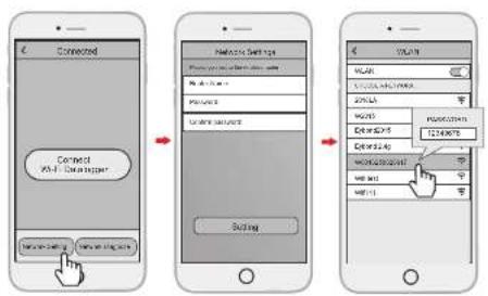
5.2 Connect Wi-Fi Datalogger
Step 1: Select the same number of WI-Fi PlugII PN to connect on your phone WLAN. (Initial Password:12345678)
Step 2: Open the APP, tap the Wi-Fi Config button to enter this page.
5.3 Network Setting
Step 1: Then tap the Network Setting button.
Step 2: According to the prompts, type in the information to finish the network setting.
Step 3: After the Wi-Fi PlugII is restarted, reconnect the Wi-Fi which connected by step 5.1.
KSTAR
User Manual User Manual
KSTAR
06 Create Account And Add Datalogger
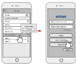
6.1 Create Account
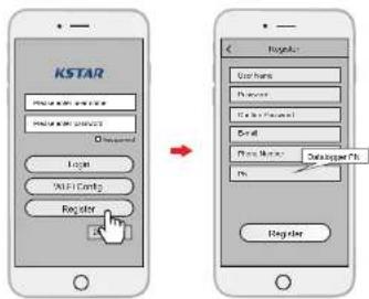
Step 1: Open the APP, tap the Register button to enter this page.
Step 2: According to the prompts, type in the information to create an account.
6.2 Add Datalogger
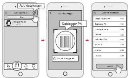
Step 1: Login the account and click the Datalogger button. Tap the "+"button on the top-right corner of the Datalogger page.
Step 2: Scan the PN on the Wi-Fi PlugII, or input it manually.
Step 3: According to the prompts, type in the information to finish add datalogger.
07 Alarm code and error code
7.1 Alarm code
| Codes | English description |
| W00 | Grid Volt Low |
| W01 | Grid Volt High |
| W02 | Grid Frequency Low |
| W03 | Grid Frequency High |
| W04 | Solar Loss |
| W05 | Bat Loss |
| W06 | Bat Under Volt |
| W07 | Bat Volt Low |
| W08 | Bat Volt High |
| W09 | Over Load |
| W10 | GFCI Over |
| W11 | LN Reverse |
| W12 | Fan Fault |
| W13 | BAT Power Down |
| W14 | BMS Discharge Over Current |
| W15 | BMS charge Over Current |
| W16 | BMS Over Volt |
| W17 | BMS Over Temp |
| W18 | BMS Discharge Low Temp |
| W19 | Bms Volt Imbalance |
| W20 | Bms Communicate Fault |
| W21 | BMS Under Volt |
| W22 | Bms Chg Temp Low |
| W23 | BMS Severe Over Volt |
| W24 | BMS Severe Over Temp |
| W25 | CT Reverse |
7.2 Error code
| Codes | English description |
| F00 | Soft Time Out |
| F01 | INV Volt Short |
| F02 | GFCI Sensor Fault |
| F04 | Bus Volt Low |
| F05 | Bus Volt High |
| F06 | Bus Short Circuit |
| F07 | PV ISO Under Fault |
| F08 | PV Input Short Circuit |
| F09 | Bypass Relay Fault |
| F10 | INV Curr Over |
| F11 | INV DC Over |
| F12 | Ambient Over Temp |
| F13 | Sink Over Temp |
| F14 | Grid Relay Fault |
| F15 | DisChg Curr Over |
| F16 | Chg Curr Over |
| F17 | Current Sensor Fault |
| F18 | INV Abnormal |
| F19 | EPS Relay Fault |
| F20 | Alway Over Load |
| F32 | SCI Fault |
KSTAR
User Manual
08 Fault diagnosis and solutions
The inverter is easy to maintain. When you encounter the following problems, please refer to the Solutions below, and contact the local distributor if the problem remains unsolved. The following table lists some of the basic problems that may occur during the actual operation as well as their corresponding basic solutions.
Fault diagnosis table
| Types | Codes Solutions | |
| Soft Time Out F00 | (1) Restart the inverter and wait until it functions normally;(2) Contact customer service if error warning continues. | |
| INV Volt Short F01 | (1) Cut off all the power and shut down all the machines; disconnect the load and plug in to restart machines, then check whether the load is short circuited if the fault has been eliminated;(2) Contact customer service if fault remains unremoved. | |
| GFCI Sensor Fault F02 | (1) Cut off all the power, Restart the inverter and wait until it functions normally.(2) Contact customer service if error warning continues. | |
| Bus Volt Low | F04F05 | (1) Check the input mode setting is correct.(2) Restart the inverter and wait until it functions normally.(3) Contact customer service if error warning continues. |
| Bus Volt Short F06 | (1) Restart the inverter and wait until it functions normally.(2) Contact customer service if error warning continues. | |
| PV ISO Under Fault | F07 | (1) Check for good ground connection;(2) Check if the earth resistance of PV+ and PV- is greater than 2MΩ;(3) If it is smaller than 2MΩ, check PV string for ground fault or poor ground insulation; if it is greater than 2MΩ, please contact the local inverter customer service once fault is not removed. |
User Manual
KSTAR
| Types | Codes | Solutions |
| PV Input Short Circuit | F08 | (1) Check the input mode setting is correct.(2) Disconnect the PV input, restart the inverter and wait until it functions normally.(3) Contact customer service if error warning continues. |
| Relay Fault | F09 | (1) Disconnect the PV input, restart the inverter and wait until it functions normally.(2) Contact customer service if error warning continues. |
| F14 | ||
| F19 | ||
| INV Current Over F10 | (1) Wait five minutes for the inverter to automatically restart;(2) Check whether the load is in compliance with the specification;(3) Contact customer service if error warning continues. | |
| INV DC Over F11 | (1) Restart the inverter and wait until it functions normally.(2) Contact customer service if error warning continues. | |
| NTC/SinkTemp Over | F12 | (1) Restart the inverter, restart the machine after a few minutes of cooling, and observe whether the machine can return to normal.(2) Check if the ambient temperature is outside the normal operating temperature range of the machine.(3) Contact customer service if error warning continues. |
| F13 | ||
| Dischg Curr Over F15 | (1) Wait one minute for the inverter to restart;(2) Check whether the load is in compliance with the specification;(3) Contact customer service if error warning continues. | |
| CHG Current Over F16 | (1) Check if battery wiring port is short circuited;(2) Check if charging current is in compliance with presetting;(3) Contact customer service if error warning continues. | |
| Current Sensor Fault F17 | (1) Restart the inverter and wait until it functions normally.(2) Contact customer service if error warning continues. | |
KSTAR
User Manual User Manual
KSTAR
| Types | Codes Solutions | |
| INV Abnormal F18 (1) Please contact the distributor. | ||
| Communication Fault F32 | (1) Restart the inverter and wait until it functions normally.(2) Contact customer service if error warning continues. | |
| Grid Fault | W00 | (1) Check if the local voltage and frequency is incompliance with the machine specification;(2) If voltage and frequency are within the acceptedrange, then wait 2 minutes for the inverter to functionnormally; but if no recovery or fault repeats, pleasecontact the local inverter customer service;(3) Contact the local power company if voltage andfrequency are beyond range or unstable. |
| W01 | ||
| W02 | ||
| W03 | ||
| Solar Loss W04 | (1) PV is not connected;(2) Check grid connection;(3) Check PV availability. | |
| Bat Loss W05 | (1) Battery is not connected;(2) Check if battery wiring port is short circuited;(3) Contact customer service if error warning continues. | |
| Bat Volt Low | W06 | (1) Check the battery availability;(2) Contact customer service if error warning continues. |
| W07 | ||
| Bat Volt High W08 | (1) Check if the battery is in line with the presetting;(2) If so, power off and restart;(3) Contact customer service if error warning continues. | |
| Over Load Warning | W09 | (1) Wait one minute for the inverter to restart;(2) Check whether the load is in compliance with thespecification; |
| CFCI Over | W10 | (1) Check PV string for direct or indirect groundingphenomenon;(2) Check peripherals of machine for current leakage;(3) Contact the local inverter customer service if faultremains unremoved. |
| LN Reverse | W11 | (1) Check whether the installation follows the instructions;(2) Contact customer service if error warning continues. |
| Fan Fault | W12 | (1) Restart the inverter and wait until it functions normally.(2) Contact customer service if error warning continues. |
| BMS Fault | W14~W25 | (1) Please contact the distributor. |
09 Machine Parameters
| Battery Specifications BluE-PACK5.1 BluE-PACK10.2 | ||
| Electrical | ||
| Energy Capacity | 5.12kWh | 10.24kWh |
| Battery type | LFP (LiFePO4) | |
| Depth of Discharge (DoD) | 90% | |
| Rated voltage | 51.2V | |
| Operating Voltage Range | 44.8~56.5Vdc | |
| Operation | ||
| Maximum Charging Current | 50A (0.5C) | 100A (0.5C) |
| Maximum Discharging Current | 80A (0.8C) | 100A (0.5C) |
| Operating temperature range | 0°C~+50°C(Charging)/-10°C~+50°C(DisCharging) | |
| Storage temperature range | -20°C~+50°C | |
| Humidity | 0% ~ 90% | |
| BMS | ||
| Modules Connection | max. 4 batteries in parallel | |
| Monitoring Parameters | System voltage, current, cell voltage,cell temperature, PCBA temperature measurement | |
| Communication | CAN and RS-485 compatible | |
| Ventilation type | Passive and Active Cooling | |
KSTAR
User Manual User Manual
KSTAR
| Physical | ||
| Weight (Kg) | 58 | 116 |
| Dimension (W×H×D)mm | 540* 0*24053 540*1 | 1020*240 |
| IP Protection | IP65 | |
| Warranty | 5Year Product Warranty, 10Year Performance Warranty | |
| Certificate | ||
| Safety(Cell) | IEC 62619、UL 1973、UN 38.3 | |
| MODEL | BluE-S-3680D | BluE-S-5000D |
| PV terminal | ||
| Vmax. PV | 580Vd.c. | |
| Rate Voltage | 400Vd.c. | |
| MPPT Voltage Range | 120~550Vd.c. | |
| MPPT Range (full load) | 184~550Vd.c. 230~550Vd.c. | |
| MPPT Tracker / Strings | 2 | |
| Max. continuous PV input current | 13Ad.c.×2 | |
| Isc PV | 16Ad.c. | |
| Max backfeed current | 0Ad.c. | |
| Max. continuous PV input power | 4800W 6500W | |
| Battery terminal | ||
| Battery type | Lithium or lead-acid batteries | |
| Voltage range | 40~60Vd.c. | |
| Rated voltage | 48Vd.c. | |
| Maximum charge/discharge current | 50Ad.c./80Ad.c. | 100Ad.c./100Ad.c. |
| Maximum charge/discharge power | 3000W/4000W | 4600W/5000W |
| Gridterminal parameter | |
| Rated voltage | 230Va.c. |
| Rated frequency | 50Hz |
| Rated input Current | 31Aa.c. |
| Maximum continuous input current | 32Aa.c. | |
| Maximum continuous input power | 7360VA | |
| Rated output Current | 16Aa.c. 22Aa.c. | |
| Maximum continuous output current | 16Aa.c. 22Aa.c. | |
| Power factor (Cos phi), adjustable | 0.8 leading ~0.8 lagging(0.95 leading ~0.95 lagging for Germany) | |
| Maximum continuous output power | 3680W 5000W | |
| max. output fault current | 102Apeak | |
| Grid port inrush current | less than 22Apeak | |
| Grid port overcurrent protection | 40A | |
| Backup load terminal parameter | ||
| Rated voltage | 230Va.c. | |
| Rated frequency | 50Hz | |
| Rated output Current | 16Aa.c. | 20Aa.c. |
| Maximum continuous output current | 16Aa.c. | 20Aa.c. |
| Rated frequency | 50/60Hz ( Fluctuation range±0.2% ) | |
| Rated continuous output power | 3680W | 4600W |
| Maximum output apparent power | 4000VA | 5000VA |
| Max. output fault current | 99Apeak | |
| Backup load overcurrent protection | 32A | |
| Generalparameter | |
| Temperature | -25°C to +60°C, derating above 45 °C |
| Protective class | Class I |
| Overvoltage Category | II(DC side), III(AC side) |
| Ingress protection | IP65 |
| Altitude | ≤ 2000m |
| Dimension (W×H×D)mm | 540*590*240 |
| Weight (Kg) | 39 |
| Relative Humidity | 0~95% (No condensation) |
KSTAR
User Manual
| Topology | High Frequency Isolation |
| Cooling | Natural Convection |
| Display | LCD/APP |
| Communication Interface | RS485/CAN2.0/WIFI |
| Max. Conversion Efficiency(From Battery) | 94.0% |
| Max. Conversion Efficiency(From PV) | 97.6% |
| Euro Efficiency | 97.0% |
| MPPT Efficiency | 99.5% |
| Protection Function | Short Circuit Protection, AC Leakage Fault Protection,Grounding Fault Protection, Anti-islanding Protection,Overload Protection、Surge Protection、DC PolarityProtection |
| Certification& Standard | |
| Grid Regulation | AS/NZS 4777.2, VDE-AR-N4105, VDE0126-1-1 |
| Safety Regulation | IEC/EN 62109-1&2, IEC62040-1 |
| EMC | EN61000-6-1, EN61000-6-2, EN61000-6-3,EN61000-6-4,EN61000-4-16, EN61000-4-18,EN61000-4-29 |
User Manual
KSTAR
Table 9.1 Grid specification (single-phase)
| Grid Specification | Output Voltage Range (Vac) | Output Frequency Range (Hz) | Boot wait time(S) |
| China | 187-252 48-50.5 30 | ||
| Germany | 184-264 47.5-51.5 60 | ||
| Australia | 180-260 47-52 60 | ||
| Italy | 184-276 49.7-50.3 60 | ||
| Spain | 196-253 48-50.5 180 | ||
| U.K. | 184-264 47-52 180 | ||
| Hungary | 196-253 49-51 300 | ||
| Belgium | 184-264 47.5-51.5 60 | ||
| W-Australia | 180-260 45-52 60 | ||
| Greece | 184-264 49.5-50.5 180 | ||
| France | 184-264 47.5-50.4 60 | ||
| Bangkok | 150-264 49-51 | 150 | |
| Thailand | 150-264 48-51 60 | ||
| Local | 150-280 45-55 30 | ||
| 60Hz | 184-264 59.5-60.5 60 |
10 Routine Maintenance
10.1 Maintenance Plan
◆ Check if wire connections are loose.
◆ Check if cables are aged/damaged.
◆ Check if cable insulating ribbon drops.
◆ Check if cable terminal is loose, any overheat sign.
◆ Check if ground connection is good.
10.1.1 Operating Environment
(Every six months)
Carefully observe whether the battery system equipment is ineffective or damaged;
When the system is running, listen to any part of the system for abnormal noise;
Check whether the voltage, temperature and other parameters of the battery and other equipment parameters are normal during system operation;
10.1.2 Equipment Cleaning
(Every six months to one year, depending on the site environment and dust content, etc.) Ensure that the ground is clean and tidy, keep the maintenance access route unblocked, and ensure that the warning and guiding signs are clear and intact. Monitor the temperature of the battery module and clean the battery module if necessary.
10.1.3 Cable, Terminal and Equipment Inspection
(Every six months to one year)
◆ Check if the cable connections are loose.
◆ Check whether the cables are aged / damaged.
◆ Check whether the cable tie of the cable has fallen off.
- Check if the cable terminal screws are loose and the terminal position has any signs of overheating.
◆ Check whether the management system of the system equipment, monitoring system and other related equipment are invalid or damaged.
◆ Check that the grounding of the equipment is good and the grounding resistance is less than 10 ohms.
10.2 Notes
After the equipment is out of operation, please pay attention to following notes while maintaining :
- Related safety standards and specifications should be followed in operation and maintenance.
◆ Disconnect all the electrical connections so that the equipment would not be powered on. - Wait at least 5 minutes after disconnection, so that the residual voltage of the capacitors drops to a safe voltage. Use a multimeter to make sure that the equipment is completely discharged.
- The equipment should be repaired by professional staff only and it is strictly forbidden for maintenance staff to open equipment modules on their own.
◆ Appropriate protective measures should be taken while maintaining, such as insulated gloves, shoes, and anti-noise ear plugs.
◆ Life is priceless. Make sure no one would get hurt first.
In case of a deep discharge, the battery must be charged to a SOC rate of 30% to 50% if the entire system is static (ie the battery has not been charged for two weeks or more).
Please contact us in time if there are any conditions that could not be explained in the manual.
11 Quality Assurance
When product faults occur during the warranty period, KSTAR or his partner will provide free service or replace the product with a new one.
Evidence
During the warranty period, the customer shall provide the product purchase invoice and date. In addition, the trademark on the product shall be undamaged and legible. Otherwise, KSTAR has the right to refuse to honor the quality guarantee.
Conditions
• After replacement, unqualified products shall be processed by KSTAR.
- The customer shall give KSTAR or his partner a reasonable period to repair the faulty device.
Exclusion of Liability
In the following circumstances, KSTAR has the right to refuse to honor the quality guarantee:
KSTAR
User Manual
- The free warranty period for the whole machine/components has expired.
• The device is damaged during transport.
• The device is incorrectly installed, refifitted, or used. - The device operates in harsh environment, as described in this manual.
- The fault or damage is caused by installation, repairs, modification, or disassembly performed by a service provider or personnel not from KSTAR or his authorized partner.
- The fault or damage is caused by the use of non-standard or non-KSTAR.
components or software.
- The installation and use range are beyond stipulations of relevant international standards.
• The damage is caused by unexpected natural factors.
For faulty products in any of above cases, if the customer requests maintenance, paid maintenance service may be provided based on the judgment of KSTAR.
12 Contact Information
18 overseas branch offices

PV inverter industry Pre-sales : (86)0755-89741234 Ext 8151
PV inverter industry After-sales : (86)0755-89741234 Ext 8729
Global overseas service mailbox : overseas_service@kstar.com.cn