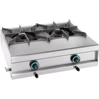
321202 - Other Kitchen Appliances Mach - Free user manual and instructions
Find the device manual for free 321202 Mach in PDF.


| Product Type | Other Kitchen Appliance |
| Brand | Mach |
| Model | 321202 |
| Dimensions (approx.) | 30 x 20 x 15 cm |
| Weight (approx.) | 2 kg |
| Power Rating | 500 W |
| Voltage | 220-240 V, 50/60 Hz |
| Main Functions | Mixing, chopping, blending, whisking |
| Control Type | Rotary dial with multiple speeds |
| Bowl Capacity | 1.5 L |
| Material | Stainless steel and plastic |
| Cleaning & Care | Wipe with damp cloth; detachable parts dishwasher safe |
| Safety Features | Overheat protection, non-slip feet, safety lock |
| Spare Parts Availability | Replacement bowls, blades, and seals available |
| Repairability | Faulty parts replaceable; professional repair recommended |
| Manual Format | PDF, 22 pages, English |
| Warranty | 2 years limited warranty |
Frequently Asked Questions - 321202 Mach
User questions about 321202 Mach
0 question about this device. Answer the ones you know or ask your own.
Ask a new question about this device
Download the instructions for your Other Kitchen Appliances in PDF format for free! Find your manual 321202 - Mach and take your electronic device back in hand. On this page are published all the documents necessary for the use of your device. 321202 by Mach.
USER MANUAL 321202 Mach
1.2. General safety instructions
natural_image
Exterior view of a stainless steel electrical appliance with a black fan cover (no visible text or symbols)FL12

natural_image
Exterior view of a stainless steel gas stove with two yellow cooling fans (no text or symbols visible)FL24
natural_image
Technical line drawing of a mechanical assembly with bolt holes and a magnified inset showing two cylindrical components (no text or symbols)natural_image
Four circular diagrams showing mechanical or electrical components with no visible text or symbolsPositie 0:
De knop is uit.
natural_image
Hand holding a circular device with internal components and directional arrows (no text or symbols)natural_image
Hand pointing at a circular switch labeled '10' with an arrow indicating left-hand motion (no text or symbols beyond the number)WORKS, REPAIRS AND SPARE PARTS
(FOR THE QUALIFIED TECHNICIAN)
This leaflet includes all the information, advises and warnings for the correct use of the gas ranges of the FL series and it is supplied with every product. The leaflet is a part of the appliance.
Before any action of installation use or maintenance we advice you to read carefully the corresponding chapters of this manual. This leaflet must be kept in safe place where it is easy to be found.
In case you sell the cooker you must deliver this to the new owner together with the appliance.
1.2. General safety instructions
This appliance has been manufactured for professional use and must be used only by qualified personnel. All works for the installation gas supply connections repairs and maintenance must be done by qualified personnel.
Any use of this appliance that is not specified in this manual from any liability for harm or injury to persons or damage to properties or the appliance.
Before using or working on the appliance is necessary to know the operation of every control reported in this manual.
The normal operation and every day's maintenance of the appliance must be done by qualified personnel.
After any action of maintenance be sure that all parts of the appliance have been replaced correctly and are in condition to operate normally.
1.3. Models
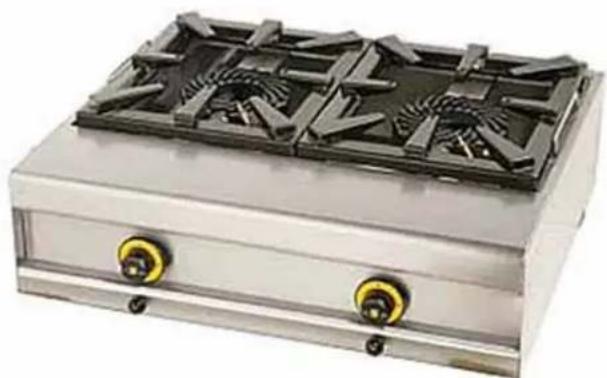
This gas operated ranges series includes the models: FL12 and FL24.

natural_image
Exterior view of a stainless steel electrical appliance with a black fan cover (no visible text or symbols)FL12
natural_image
Exterior view of a stainless steel gas stove with two yellow cooling fans (no text or symbols visible)FL24
1.4. Technical characteristics
The frame of the appliance is made of stainless steel and the grids for the pan support are enamelled and designed to work under heavy loads.
The valves controlling the gas supply are equipped with safety devices (thermocouples) that interrupt the flow of gas in case of accidental blow – off of the burners.
The burners can work in heavy working conditions and are in conformity with the corresponding norms for safety.
PART TWO INSTALLATION INSTRUCTIONS FOR THE QUALIFIED IN TECHNICIAN
2.1. Installation
The installation, connection to the gas supply and putting in operation of the unit, must be done by qualified technician, who must follow the corresponding regulations for safety in the room where the appliance is installed.
The unit must be installed in well ventilated room, possibly under an aspirator to ensure the absolute removal of the burned gasses.
2.2. Special regulations for the installation
We have to remind you that the installation of cooking appliances working with gas, in rooms were public has access, must be done according the corresponding regulations:
- Safety regulation for danger of accidents because of panic in public places.
- General regulations valid for our installation of burning gasses and liquid fuel. (Follow the special instructions according the type of gas you use).
- Heating, ventilation and cooling -Installation of cooking appliances for restaurants.
2.3. Installation
Put the cooker out of its packing and inspect that everything is in order. Inspect also all parts for any damage that possibly happened to it during the transportation.
Before you put the unit in operation for the very first time remove the plastic coating from the stainless steel surfaces and clean them, if it is necessary, with solved to remove the coating's clue.
Put the cooker to the desired place.
2.4 Preliminary inspection:
Be sure that the appliance is adjusted to operate for the gas available in the installations supply. If the available gas is different you have to adjust the cooker according the description in the chapter 2.11.
Usually the appliance is already adjusted to operate with LPG.
Special indications in the packing and on the cooker's body describe how the unit is adjusted to operate.
2.5 Connection
The connection to the gas network or tank must be done with flexible hose or metal pipes of the corresponding diameter. A gasket and/or Teflon film must be used to ensure gas tight connection. A gas switch must be in line to cut off the gas supply when the appliance is not in use. When the gas connection is complete, all fixings must be inspected for gas leakage. For this inspection use the special sprays sold for this use or a gas leakage detecting equipment.
Do not inspect for gas leakage using open flame.
This appliance must not be installed near flammable surfaces and must be in a distance at least 10 cm from the nearest wall.
The company does not accept any responsibility for damages to persons, or objects caused because of ignoring these instructions.
2.6 Power
This appliance operates in its nominal power with the injectors supplied with it.
The pressure of the gas supplied to the unit must correspond to the values reported on the label attached on it.
If the pressure of the gas in your installation is not in accordance with the above values the appliance must not be connected.
2.7 Pressure control
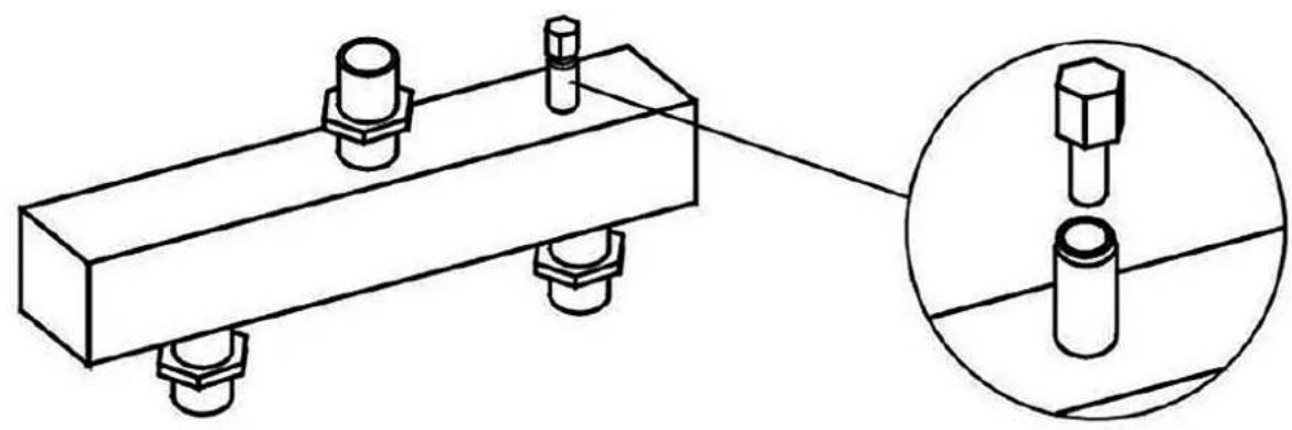
The gas supply pressure can be inspected with the proper manometer that the technician will connect to the pressure control nipple. The nipple is located on the gas supply pipe a few cm from the point of the appliance's gas inlet. The user can have access to that point by removing the pan support grid. To do the connection on the nipple follow the instructions:
Unscrew the sealing nut and remove it from the nipple that is located on the pipe of the main supply.
Fix the manometer and put the appliance in operation following the instructions given to the next paragraphs. Inspect the gas pressure.
Remove the manometer and put the sealing nut back on the nipple. Ensure that the sealing nut is gas tight fixed.
natural_image
Technical line drawing of a mechanical assembly with bolt holes and a magnified inset showing two cylindrical components (no text or symbols)2.8 Operating the ranges
Gas ranges control switches are located on the front panel of the appliance.
Each one controls one range and has four positions.
If you wish to change the position press lightly the switch keep it pressed, and turn.

Position zero:
The switch is off.
No gas supply to the corresponding range.
Ignition's position:
Normal gas supply to the jet of the range controlled by this switch.
The gas flow exists only if the thermocouple is already warm or if the switch is pressed in.
This position to the gas switch is a necessary step when starting fire to the range.
Big flame position:
Normal gas supply to the range controlled by this switch.
The range operates with its maximum heating power. Normal cooking operation.
Small flame position:
Reduced gas supply to the range controlled by this switch.
The range operates in low heating power.
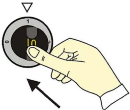
This appliance is equipped with safety devices to protect people and their properties from erroneous operations. For this reason the user has to follow next procedure every - when he wish to start fire to the ranges.
1) Turn the switch to the position for ignition. To do it press the switch lightly and turn counter - clockwise.

natural_image
Hand holding a circular device with internal components and directional arrows (no text or symbols)2) When the switch is turned, press it inside and keep it pressed for 10 - 15 seconds to let gas flow to the pilot
natural_image
Hand pointing at a circular dial with number 1 and arrow, no text or symbols present3) Continue keeping the switch pressed and start fire with a lighter to the burner of the corresponding range. After the fire start continue keeping the switch pressed for 10 - 15 seconds to let thermocouple (the safety device) become activated.
Now you can release the switch if the fire remains all safety devices are activated and you can use the range normally, if the fire stops repeat the above procedure
Start fire to the range by turning the switch to the desirable position (big or small flame). When you finish your work and you wish to blow out the range turn the switch to the position zero.
2.10 Inspection of the operation.
- Inspect for gas leakage as reported in the paragraph 2.5.
- Ensure that in the place where the unit is installed there is good ventilation.
- Inspect the flame in main burner and ensure that it looks normal.
- Be sure for the stability of the flame in the main burner by a turning the temperature selector a few times to the highest and lowest position.
2.11 Adjustment to a different type of gas
- To adjust the appliance for another type of gas than the one that the unit is prepared it in the factory you have to replace the injectors of the burners.
- The necessary injectors are supplied with the appliance in a plastic bag.
- To replace the injector in the main burners follow the procedure:
- The burners must be cold, switched off and the gas supply switch closed.
- Remove the tray under the unit and pick it up enough high to have access to the burner from the bottom of the appliance.
- With a 7 mm spanner remove the nuts holding the primary air adjuster (galvanized ring) and pull it away from the injector's opening.
- Unscrew the injector and replaced it with the one of the correct type.
- Move the primary air adjuster to the correct position to have a bright blue flame without yellow flashes and fix it by screwing the nuts.
PART THREE - MAINTENANCE AND CLEANING (INSTRUCTIONS FOR THE USER)
3.1. Use and maintenance
- We remind you one more time that this appliance is for professional use and must be operated only by specially treated personnel.
- The personnel who is responsible for the technical works like the connection and initial operation, has the obligation to inform the everyday users how to operate and maintain this appliance.
- Before any work of maintenance is necessary to turn off the switch in the gas supplying line of your installation.
- We advice the user to make a contract of maintenance with a qualified technician where should be a detailed list of inspections on the appliance for every year.
- If you follow carefully the instructions reported in this manual you will have perfect use and a long life of your SER GAS cookers.
- The manufacturer does not accept any responsibility for possible damages should be caused on persons, animals or property because of incorrect use of the appliance or because of ignoring the instructions reported in this manual.
Important! The gas valves have adjusting screws sealed with lack. This sealing must never be removed and the screws must never be touched.
3.2. Cleaning
The appliance must be kept carefully clean especially in its inner parts using warm water and dishwashing detergent or the special products for cleaning similar appliances. We advice you to be sure that the products used in your oven do not contain drastic chemicals and that they are proper for cleaning stainless steel.
PART FOUR
WORKS, REPAIRS AND SPARE PARTS
(FOR THE QUALIFIED TECHNICIAN)
4.1. Bad operation
Even with a correct operation of the appliance it is possible to face-up failures that are caused of different reasons. In the following board reported some possible failures and some directions to solve the problems.
| Trouble Causes | and corrective measures |
| Smell of gas | Can be caused of gas leakage. Inspect the piping supplying gas to the unit as described in the paragraph 2.5 |
| Smell of non burned gas | Inspect that the burning is normal. Inspect that the gas consumption is not excessive. Inspect that the burned gas can flow away freely.Inspect for the correct operation of the aspirator and ventilation of your place. |
| The pilot burner blows off | Ensure that the flame is enough to warm well the thermocouple.Adjust the distance between the thermocouple and the burner.Inspect that the thermostatic valve operates normally. |
| The pilot does not light on | Inspect that the thermocouple is well seated on its holder.It is possible to have loose of power on the piping or the injector is corked. Inspect that the thermostatic valve operates normally. |
| "Explosions" to the burners. | Inspect the pressure of the gas Inspect that the thermocouple is not too far away from the main burner |
| The main burner does not lights on | Inspect that there is no loose of power on the piping or that the injector is not corked. The burner's parts is possible not to be well fixed.The thermostatic valve can have problem. |
Attention!
At the end of every work of maintenance or repair you have done on gas parts it is necessary to inspect for gas leakage.
| Length (mm) | Depth (mm) | Height (mm) | Power (kW) | |
| *321.201/*321.211 | 390 | 600 | 230 | 7.5 |
| *321.202/*321.212 | 740 | 600 | 230 | 15 |
Types of gases used
| FR -BE | G30 / G31G20 / G25 | 3+2E+ | 28 -30/37 mbar20/25 mbar | () () |
| GB | G30 / G31G20 | 3+2H | 28-30/37 mbar20 | () () |
| NL | G30 / G31G25 | 3B/P2L | 30 mbar25 mbar | () () |
| LU | G20 | 2E | 20 mbar | () |


- General safety instructions
- Positie 0:
- WORKS, REPAIRS AND SPARE PARTS
- (FOR THE QUALIFIED TECHNICIAN)
- Models
- Technical characteristics
- PART TWO INSTALLATION INSTRUCTIONS FOR THE QUALIFIED IN TECHNICIAN
- Installation
- Special regulations for the installation
- Installation
- Preliminary inspection:
- Connection
- Do not inspect for gas leakage using open flame.
- Power
- Pressure control
- Operating the ranges
- Position zero:
- Ignition's position:
- Big flame position:
- Small flame position:
- Inspection of the operation.
- Adjustment to a different type of gas
- PART THREE - MAINTENANCE AND CLEANING (INSTRUCTIONS FOR THE USER)
- Use and maintenance
- Important! The gas valves have adjusting screws sealed with lack. This sealing must never be removed and the screws must never be touched.
- Cleaning
- PART FOUR
- Bad operation
- Attention!
Brand : Mach
Model : 321202
Category : Other Kitchen Appliances