ES-5104PH V2 - Switch Edimax - Free user manual and instructions
Find the device manual for free ES-5104PH V2 Edimax in PDF.

User questions about ES-5104PH V2 Edimax
0 question about this device. Answer the ones you know or ask your own.
Ask a new question about this device
Download the instructions for your Switch in PDF format for free! Find your manual ES-5104PH V2 - Edimax and take your electronic device back in hand. On this page are published all the documents necessary for the use of your device. ES-5104PH V2 by Edimax.
USER MANUAL ES-5104PH V2 Edimax
No. 278, Xinhu 1st Rd., Neihu Dist., Taipei City, Taiwan
Email: support@edimax.com.tw
Edimax Technology Europe B.V.
Fijenhof 2, 5652 AE Eindhoven, The Netherlands
Email: support@edimax.nl
Edimax Computer Company
3444 De La Cruz Blvd., Santa Clara, CA 95054, USA
Live Tech Support: 1(800) 652-6776
Email: support@edimax.com
ES-5104PH V2: 5-Port Fast Ethernet Switch with 4 PoE+ Ports
Package Contents
Before you start using this product, please check if there is anything missing in the package, and contact your dealer to claim the missing item(s):
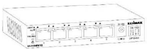
text_image
UNITS PORT 6 EN-310F872 T A T A T A 2 3 4 5 DC/3V EN YTD 1 2 3 4 DC/300PoE+ Switch

text_image
IDIMAX Quick Installation GuideQIG
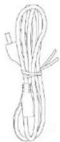
Power Cord
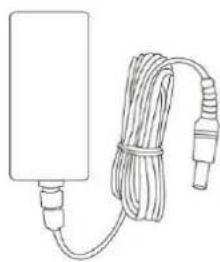
natural_image
Line drawing of a rectangular device connected to a coiled cable with connectors (no text or symbols)Power Adapter
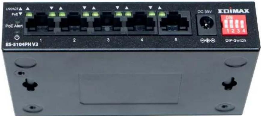
Front Panel:
Please refer to the following descripon for the front panel:
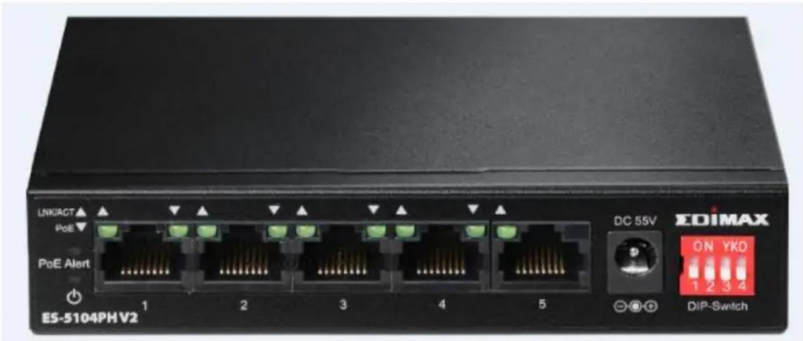
text_image
LNKACT PoE PoE Alert ES-5104PHV2 1 2 3 4 5 DC 55V EDIMAX ON YKO 1 2 3 4 DIP-SwitchES-5104PH V2
DIP Switch Denion:
The front pnael of PoE+ switch provies four pins DIP Switch. The detailed descripons are shown nin the following table.
| DIP Switch | Status | Descripon |
| 1(Extend) | On | This mode makes the PoE+ Port 1~2 operate at auto-negoaon 10Mbps speed duplex mode only, but the delivery distance of PoE power and network data can reach 200m. |
| O (default) | This mode makes the PoE+ Port 1~2 operate as a genral switch. | |
| 2(Extend) | On | This mode makes the PoE+ Port 3~4 operate at auto-negoaon 10Mbps speed duplex mode only, but the delivery distance of PoE power and network data can reach 200m. |
| O (default) | This mode makes the PoE+ Port 3~4 operate as a genral switch. | |
| 3 | On | This mode makes the PoE+ switch |
| (VLAN) | operate as a VLAN isolaon switch and port 1 to port 4 will isolate respectively., port 1 to port 4 can only communicate with port 5 (uplink port). | |
| O (default) | This mode makes the PoE+ switch operate as a genral switch. | |
| 4 (QoS) | On | This mode makes the PoE+ switch operate as a QOS switch, it follows the Video & Voice Trac High Priority in QoS service. |
| O | This mode makes the PoE+ switch operate as a genral switch. |
Please note, aer truning ON the DIP switch you will have to Reboot the switch.
Aer installing the switch, you can check its status from the LED inducators on the front panel shown below.
LED Denions:
| LED | Color | LED Status | Descripon |
| Power ⏻ | Green | On | Switch is on. |
| O | Switch is o. | ||
| LNK/ACT | Green | On | Connected to 10/100M network. |
| Flashing | Transferring/receiving data. | ||
| Off | No device is connected. | ||
| PoE | Green | On | Feeding power to PoE devices. |
| O | PoE funcon is not acve. | ||
| PoE Alert | Red | On | Total PoE power consumed is exceeding PoE budget. |
| O | Total PoE power is within PoE budget. |
Back Panel:
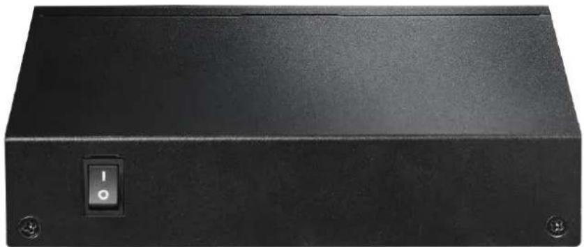
natural_image
Black rectangular electronic device with a circular switch labeled 'I' and two mounting holes (no text or symbols beyond the switch)Wall Mount Opon
text_image
LN6/ACT PoE PoE Alert ES-5104PH V2 1 2 3 4 5 DC 55V EDIMAX ON 1 2 3 4 DIP-SwitchThe switch can be mounted on a wall.
Measure the distance between the 2 mounng holes and screw a screw each into the wall. Carefully place the unit onto the wall by covering the caps of the screw with the mounng holes.
Operang Environment
This switch must be installed and operated within the limits of the specied operang temperature 0 - 40°C (32 - 104°F) and humidity (10 - 90% non-condensing).
- Do not place objects on top of the unit.
- Do not obstruct any vents at the sides of the unit.
- Do not posion the unit close to any heang source such as a heater, radiator or in direct exposure to sun.
- Take care to ensure the unit does not come into contact with water. Consider using a dehumidier to reduce humidity and prevent moisture entering the unit.
Connecng to Network Devices
The RJ-45 ports on the switch support Auto-MDI/MDI-X which allows either straight-through or cross-over type cables to connect this switch to a workstaon or switch.
Connect one end of the network cable to the RJ-45 port on the side panel, and connect the other end of the network cable to the RJ-45 port on the network device. Follow the same procedure to connect all RJ-45 ports of the switch.
The UTP network cables must comply with EIA/TIA 568 specicaons and Category 5 standard for data transmission. The maximum length for a UTP cable segment between the switch and connected devices is 100 meters (300).
Once the network cable is connected to both ends and the aached network device is powered on, the green LNK/ACT LED should be lit.
Connecng The Power
Connect the power adapter to the power connector of the unit; the green power LED on the front panel should be lit.

flowchart
graph LR
    A["Internet"] --> B["ADSL or Cable Modem"]
    B --> C["Router"]
    C --> D["ES-5104PH V2"]
    D --> E["IP Camera"]
    D --> F["Smart TV"]
    D --> G["IP Phone"]
    D --> H["Laptop"]
    D --> I["Media Player"]
    D --> J["Game Console"]
PoE Devices
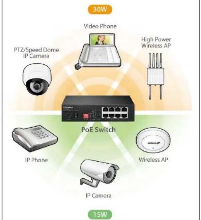
text_image
30W Video Phone PTZ/Speed Dome IP Camera High Power Wireless AP PoE Switch IP Phone Wireless AP IP Camera 15WTROUBLESHOOTING
1. Power LED is not lit.
Check if the power cord is properly connected to the external power adapter and the power source. Make sure the DC power jack is rmly plugged into the power socket of the switch.
2. Link/Acvity (LNK/ACT) LED is not lit when connected to devices.
- Ensure that the network device aached to the switch is switched on.
- Check the network cable; ensure it is properly connected to the switch and the network device.
- Check the network cable; ensure the UTP cable complied with EIA/TIA 568 and Category 5 speciaons.
[!] Contact your dealer if problems persist.
COPYRIGHT
Copyright © Edimax Technology Co., Ltd. all rights reserved. No part of this publicaon may be reproduced, transmied, transcribed, stored in a retrieval system, or translated into any language or computer language, in any form or by any means, electronic, mechanical, magnec, opcal, chemical, manual or otherwise, without the prior written permission from Edimax Technology Co., Ltd.
Edimax Technology Co., Ltd. makes no representaons or warranes, either expressed or implied, with respect to the contents hereof and specifically disclaims any warranes, merchantability, or tness for any parcular purpose. Any soware described in this manual is sold or licensed as is. Should the programs prove defecve following their purchase, the buyer (and not this company, its distributor, or its dealer) assumes the enre cost of all necessary servicing, repair, and any incidental or consequential damages resulting from any defect in the soware. Edimax Technology Co., Ltd. reserves the right to revise this publicaon and to make changes from me to me in the contents hereof without the obligaon to nofy any person of such revision or changes.
The product you have purchased and the setup screen may appear slightly dierent from those shown in this QIG. The soware and specicaons are subject to change without noce. Please visit our website www.edimax.com for updates. All brand and product names menoned in this manual are trademarks and/or registered trademarks of their respective holders.
Federal Communicaon Commission Interference Statement
This equipment has been tested and found to comply with the limits for a Class A digital device, pursuant to Part 15 of the FCC Rules. These limits are designed to provide reasonable protecon against harmful interference when the equipment is operated in a commercial environment. This equipment generates, uses, and can radiate radio frequency energy and, if not installed and used in accordance with the instrucon manual, may cause harmful interference to radio communicaons. Operaon of this equipment in a residential area is likely to cause harmful interference in which case the user will be required to correct the interference at his own expense.
FCC Radiaon Exposure Statement
This device complies with FCC radiaon exposure limits set forth for an uncontrolled environment and it also complies with Part 15 of the FCC RF Rules. This equipment must be installed and operated in accordance with provided instrucons and the antenna(s) used for this transmier must be installed to provide a separaon distance of at least 20 cm from all persons and must not be co-located or operang in conjuncon with any other antenna or transmier. End-users and installers must be provided with antenna installaon instrucons and consider removing the no-collocaon statement.
This device complies with Part 15 of the FCC Rules. Operaon is subject to the following two conditions:
(1) this device may not cause harmful interference, and
(2) this device must accept any interference received, including interference that may cause undesired operaon.
Cauon!
Any changes or modicaons not expressly approved by the party responsible for compliance could void the user's authority to operate the equipment.
R&TTE Compliance Statement
This equipment complies with all the requirements of DIRECTIVE 2014/30/EU OF THE EUROPEAN PARLIAMENT AND THE COUNCIL of March 9, 1999 on radio equipment and telecommunicaon terminal equipment and the mutual recognition of their conformity (R&TTE). The R&TTE Directive repeals and replaces in the directive 98/13/EEC (Telecommunicaons Terminal Equipment and Satellite Earth Staon Equipment) As of April 8, 2000.
Safety
This equipment is designed with the utmost care for the safety of those who install and use it. However, special aenon must be paid to the dangers of electric shock and stac electricity when working with electrical equipment. All guidelines of this and of the computer manufacture must therefore be allowed at all mes to ensure the safe use of the equipment.
EU Countries Intended for Use
The ETSI version of this device is intended for home and oce use in Austria, Belgium, Bulgaria, Cyprus, Czech, Denmark, Estonia, Finland, France, Germany, Greece, Hungary, Ireland, Italy, Latvia, Lithuania, Luxembourg, Malta, Netherlands, Poland, Portugal, Romania, Slovakia, Slovenia, Spain, Sweden, Turkey, and United Kingdom. The ETSI version of this device is also authorized for use in EFTA member states: Iceland, Liechtenstein, Norway, and Switzerland.
EU Countries Not Intended for Use
None
EU Declaraon of Conformity
English: This equipment is in compliance with the essenal requirements and other relevant provisions of Direcve 2014/30/EU.
WEEE Directive & Product Disposal

At the end of its serviceable life, this product should not be treated as household or general waste. It should be handed over to the applicable collecon point for the recycling of electrical and electronic equipment, or returned to the supplier for disposal.
Declaraon of Conformity
We, Edimax Technology Co., Ltd., declare under our sole responsibility, that the equipment described below complies with the requirements of the European R&TTE directives.
Equipment: 5-Port Fast Ethernet Switch with 4 PoE Ports
Model No.: ES-5104PH V2
The following European standards for essenal requirements have been followed:
Direcves 2014/30/EU
EMC : EN 55032:2012+AC:2013 Class A
EN 61000-3-2:2014 Class A
EN 61000-3-3:2013
EN 55024:2010
Direcves 2014/35/EU
Safety (LVD) : IEC 62368-1:2014 (2nd Edion) and/or EN 62368-1:2014+A11:2017
Edimax Technology Europe B.V.
Fijenhof 2,
5652 AE Eindhoven,
The Netherlands
Printed Name: David Huang
Title: Director
Edimax Technology Europe B.V.
a company of:
Edimax Technology Co., Ltd.
No. 278, Xinhu 1st Rd.,
Neihu Dist., Taipei City,
Taiwan

Date of Signature: Nov., 2020
Signature:

Printed Name: Albert Chang
Title: Director
Edimax Technology Co., Ltd.