
74-020 - Uncategorized IDEAL - Free user manual and instructions
Find the device manual for free 74-020 IDEAL in PDF.


| Product Type | Conduit Bender with Handle |
| Model Number (Handle) | 74-020 |
| Handle Length | 44 inches |
| Handle Material | Extra High Strength Steel |
| Bender Head Material | Ductile Iron or Lightweight Aluminum |
| Compatible Conduit | 1" EMT, 3/4" and 1" Rigid/IMC |
| Bender Marks | Arrow, Rim Notch, Star-Point, Degree Scale |
| Bending Capabilities | Stub, Back-to-Back, Offset, Saddle, Hickey |
| Take-Up For Stubs | 6 inches (for 3/4" EMT) |
| Offset Bending | 22.5°, 30°, 45°, 60° angles supported |
| Saddle Bend Angles | 45° center with 22.5° outer, or 60° center with 30° outer |
| Operation | Heavy foot pressure when bending on floor; body pressure close when in air |
| Correction for Overbend | Use back pusher or expanded end of handle to straighten |
| Shrinkage Consideration | Allow for shrink amount when bending offsets (see table) |
| Maintenance | Keep conduit in bender groove to prevent kinking; clean after use |
| Safety | Use proper foot pressure to avoid slipping; wear protective gear |
| Included Accessories | None (handle only; bender head sold separately) |
| Warranty | Manufacturer warranty applies (details not specified) |
Frequently Asked Questions - 74-020 IDEAL
User questions about 74-020 IDEAL
0 question about this device. Answer the ones you know or ask your own.
Ask a new question about this device
Download the instructions for your Uncategorized in PDF format for free! Find your manual 74-020 - IDEAL and take your electronic device back in hand. On this page are published all the documents necessary for the use of your device. 74-020 by IDEAL.
USER MANUAL 74-020 IDEAL
natural_image
Close-up of a person's foot stepping on a metal bicycle pedal, showing tread pattern and measurement markings (no text or symbols)Bender Guide
Features
Your IDEAL Bender has engineered features which include:
1. Arrow
To be used with stub, offset and outer marks of saddle bends.
2. Rim Notch
Locates the center of a saddle bend.
3. Star-Point
Indicates the back of a 90° bend.
4. Degree Scale
For offsets, saddles and those special situations.
5. A Choice
High strength ductile iron or light weight aluminum.
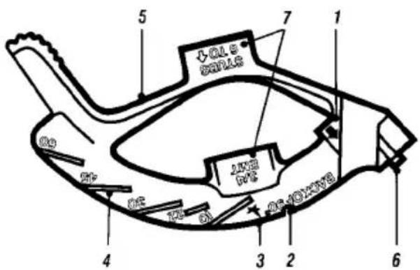
The above are features that lead to perfectly predictable and repeatable bends.
Instructions
Bend conduit with skill and professionalism. Take the guess-work out of bending.
Steps to Remember
Step 1. Measure your job.
Step 2. Mark you conduit using the recommended tables.
Step 3. Use your bender's engineered marks.
Note: Reference to the above Steps 1, 2, and 3 will be made throughout this booklet.
Don't Forget
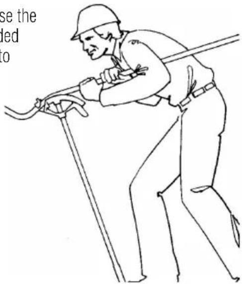
- When bending on the floor, pin the conduit to the floor. Use heavy foot pressure.
- When bending in the air, exert pressure as close to your body as possible.
- In case you overbend, use the back pusher or the expanded end of the bender handle to straighten your conduit to fit the job.
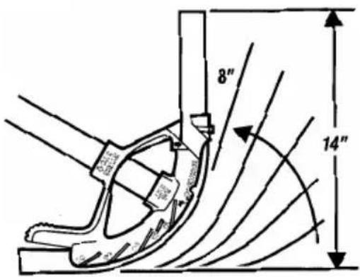
How to Bend a Stub
The stub is the most common bend. Note that your bender is marked with the "take-up" of the arc of the bender shoe.
Example:
Consider making a 14" stub, using a 3/4" EMT conduit.
Step 1. The IDEAL bender indicates stubs 6" to ↑. Simply subtract the take-up, or 6", from the finished stub height. In this case 14" minus 6" = 8".
Step 2. Mark the conduit 8" from the end.
Step 3. Line up the Arrow on the bender with the mark on the conduit and bend to 90°.
Remember: Heavy Foot pressure is critical to keep the EMT in the bender groove and to prevent kinked conduit.
How to Make Back-To-Back Bends
A back-to-back bend produces a "U" shape in a single length of conduit. Use the same technique for a conduit run across the floor or ceiling which turns up or down a wall.
Example:
Step 1. After the first 90^ bend has been made, measure to the point where the back of the second bend is to be, "B".
Step 2. Measure and mark your conduit the same distance, mark "B".
Step 3. Align the mark on the conduit with the Star-Point on the bender and bend to 90°.
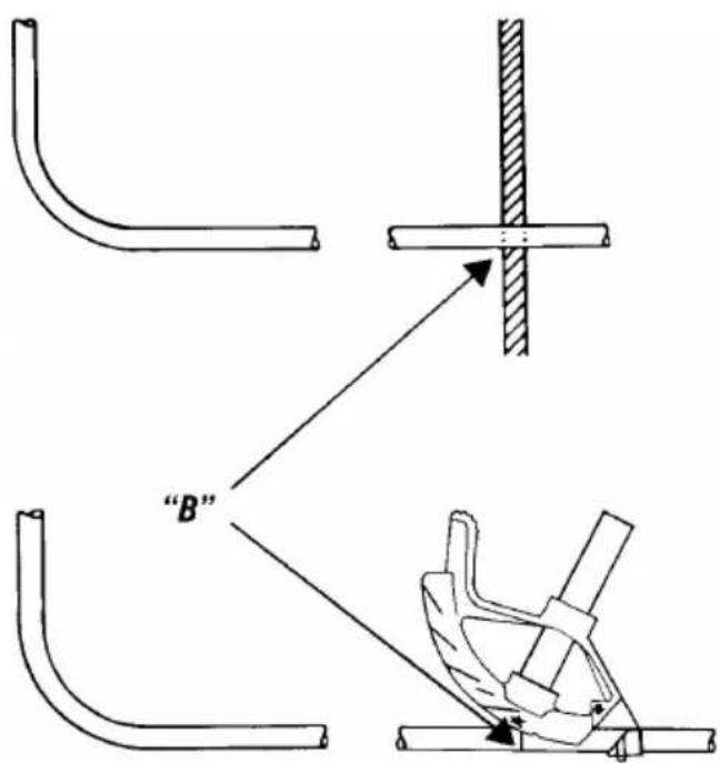
Star-Point on bender must be referenced for accurate bends.
How to make an Offset Bend
The offset bend is used when an obstruction requires a change in the conduit's plane.
Before making an offset bend, you must choose the most appropriate angles for the offset. Keep in mind that shallow bends make for easier wire pulling, steeper bends conserve space.
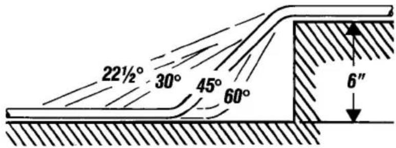
You must also consider that the conduit shrinks due to the detour. Remember to ignore the shrink when working away from the obstruction, but be sure to consider it when working into it.
Example:
Step 1. Measure the distance from the last coupling to the obstruction.
Step 2. Add the “shrink amount” from the table on page 5 to the measured distance and make your first mark. Your second mark will be placed at the “distance between bends.” (Refer to table on page 5.)
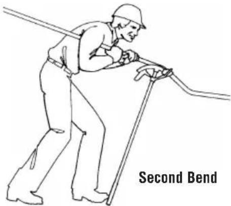
Step 3. Align the Arrow with the first mark and using the Degree Scale bend to the chosen angle. Slide down the conduit and rotate conduit 180°, align the Arrow and bend as illustrated.
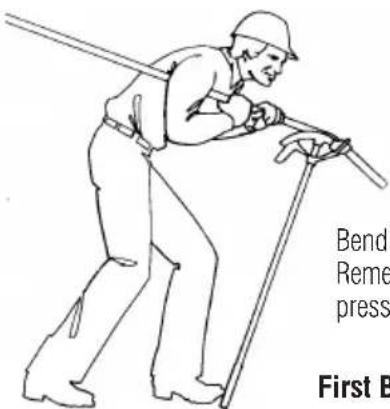
Bend offsets in the air. Remember to keep your body pressure close to the bender.
First Bend
Example:
30° Bend with a 6" Offset Depth
Distance Between Bends ← 12" | 1-1/2" → Shrink Amount
Reference Table for Offset Bends
Degree of Bend
| Offset Depth (Inches) | 22-1/2° | 30° | 45° | 60° | ||||
| 2" 5-1/4" 3/8" | ||||||||
| 3" 7-3/4" 9/16" 6" 3/4" | ||||||||
| 4" 10-1/2" 3/4" 8" 1" | ||||||||
| 5" 13" 15/16" 10" 1- /4" 7" 1-7/8" | ||||||||
| 6" 15-1/2" 1-1/8" 12" 1-1/2" 8-1/2" | 2-1/4" 7-1/4" 3" | |||||||
| 7" 18-1/4" 1-5/16" 14" 1-3/4" 9-3/8" 2-5/8" 8-3/8" 3-1/2" | ||||||||
| 8" 20-3/4" 1-1/2" 16" 2" 11-1/4" 3" | 9-5/8" 4" | |||||||
| 9" 23-1/2" 1-3/4" 18" 2-1/4" 12-1/8" | 3-3/8" 10-7/8" | 4-1/2" | ||||||
| 10" | 28" 1-7/8" 20" 2-1/2" | 4" 3-3/4" 12" 5" | ||||||
How to Make Saddle Bends
The saddle bend is similar to an offset bend, but in this case the same plane is resumed. It is used most often when another pipe is encountered.
Most common is a 45^ center bend and two 22-1/2^ outer bends, but you can use a 60^ center bend and two 30^ bends.

natural_image
Simple line drawing of a curved pipe or duct with a circular opening, no text or symbols present.Important: Use the same calculation for either set of angles.
Example:
Step 1. You encounter a 3" O.D. pipe 4 feet from the last coupling. The formula shown in the chart below indicates that for each inch of outside diameter of the obstruction, you must move your center mark ahead 3/16" per inch of obstruction height and make your outer marks 2-1/2" per inch of obstruction height from the center mark.
Step 2. The following table gives the actual mark spacings. In this example, the center mark is moved ahead 9/16" to 48-9/16". The outer marks are 7-1/2" from the center mark, or 41-1/16" and 56-1/16". Mark you conduit at these points.
| If Obstruction is | Move Your Center Mark Ahead | Make Outside Marks From Center Mark |
| 1" 3/16" 2-1/2" | ||
| 2" 3/8" 5" | ||
| 3" 9/16" 7-1/2" | ||
| 4" 3/4" 10" | ||
| 5" 15/16" 12-1/2" | ||
| 6" 1-1/8" 15" |
Step 3.
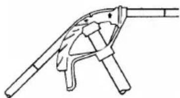
(A) Align the center mark with the Rim Notch and bend to 45^ .
(B) Do not remove the conduit from the bender. Slide the bender down to the next mark and line up with the Arrow. Bend to 22-1/2° as indicated.
(C) Remove and reverse the conduit and locate the other remaining mark at the Arrow. Bend to 22-1/2° as indicated.
natural_image
Line drawing of a mechanical device with lever and handle (no text or symbols)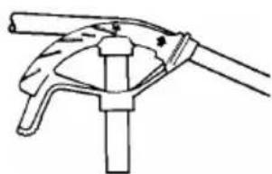
natural_image
Line drawing of a mechanical clamp or bracket assembly (no text or symbols)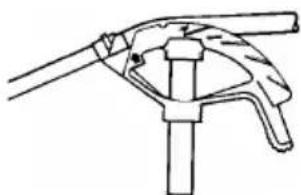
natural_image
Line drawing of a hand holding a tool or clamp (no text or symbols)Be sure to line up all bends to be in the same plane.
Hickeys
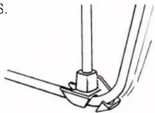
Hickeys require a different approach to bending. It is not a fixed radious device but rather one that requires several movements per bend. The hickey can give you the advantage of producing bends with a very tight radius.
natural_image
Pure mechanical diagram showing a lever and shaft assembly without any text or symbolsOrder Information
| Conduit Size | Ductile Iron Bender | Bender | Aluminum Hickey | Handle | |
| EMT | |||||
| 1/2" | 74-001 | 74-031 | 74-010 | 74-019 | |
| 3/4" | 74-002 | 74-032 | 74-011 | 74-019 | |
| 1" | 74-003 | 74-033 | 74-012 | 74-020 | |
| 1-1/4" | 74-006 | 74-036 | 74-013 | 74-021 | |
| Rigid/IMC | |||||
| 1/2" | 74-002 | 74-032 | 74-011 | 74-019 | |
| 3/4" | 74-003 | 74-033 | 74-012 | 74-020 | |
| 1" | 74-006 | 74-036 | 74-013 | 74-021 | |
| Handles | |||||
| 3/4" IPS 38" Long Expanded Extra High Strength Handle | 74-019 | ||||
| 1" IPS 44" Long Extra High Strength Handle | 74-020 | ||||
| 1-1/4" IPS 54" Long Extra High Strength Handle | 74-021 | ||||
The IDEAL bender line gives you the engineering design, indicator marks and durability to bend conduit with ease and confidence.
Brand : IDEAL
Model : 74-020
Category : Uncategorized