
DWB09E152I - Range hood BOSCH - Free user manual and instructions
Find the device manual for free DWB09E152I BOSCH in PDF.
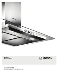


| Product Type | Range Hood |
| Brand | Bosch |
| Model | DWB09E152I |
| Installation Type | Wall-mounted |
| Operating Modes | Exhaust air mode and circulating-air mode |
| Fan Speed Settings | 3 fan speeds + intensive setting |
| Lighting Type | Interchangeable bulbs (halogen, filament, or LED) |
| Filter Type | Metal-mesh grease filter (washable) |
| Optional Filter | Activated carbon filter for recirculation mode |
| Control Type | Electronic push buttons (multiple variants) |
| Material | Stainless steel |
| Max Weight | 40 kg |
| Recommended Duct Diameter | 150 mm (min 120 mm) |
| Electrical Connection | 220-240 V, 50/60 Hz |
| Safety Features | Safety caps, automatic switch-off for intensive mode |
| Cleaning | Grease filters dishwasher-safe; stainless steel surfaces with mild cleaner |
| Warranty | 2 years (standard) |
Frequently Asked Questions - DWB09E152I BOSCH
User questions about DWB09E152I BOSCH
0 question about this device. Answer the ones you know or ask your own.
Ask a new question about this device
Download the instructions for your Range hood in PDF format for free! Find your manual DWB09E152I - BOSCH and take your electronic device back in hand. On this page are published all the documents necessary for the use of your device. DWB09E152I by BOSCH.
USER MANUAL DWB09E152I BOSCH
Extractor hood
Extractor hood

BOSCH
Instructions for installation and use
Instructions for installation and use
Table of contents
Safety instructions....2
Operating modes....3
Exhaust mode....3
Recirculation mode....3
Operation 4
Installing and removing filters....4
Cleaning and maintenance....5
Replacing the bulb 5
Installation instructions 6
Safety precautions.... 6
Duct dimensions....6
Checking the wall....7
Preparing for installation....7
Installation....7
Connecting the flue duct 9
⚠️ Safety instructions
General information

With edge extraction duct
- Pull down the metal mesh grease filter.

Installing the metal mesh grease filter
- Insert the metal mesh grease filter.


Securing the appliance
Connecting the duct
en
Table of contents
Safety instructions....10
Operating modes....11
Exhaust air mode 11
Circulating-air mode 11
Operation 12
Installing and removing filter 12
Cleaning and care ....13
Replacing bulbs....13
Installation instructions.... 14
Safety notes 14
Pipe dimensions.... 14
Checking the wall 15
Preparing the installation....15
Installation 15
Attaching flue duct.... 17

Safety instructions
General information
Follow these instructions, in particular the safety instructions. The appliance can only be used safely if it is correctly installed according to the safety instructions. Retain the instructions for subsequent use or for the next owner.
This appliance is designed to be used in the home only. The manufacturer is not liable for damage which is caused by improper use or incorrect operation.
Danger of suffocation!
from packaging material. Never allow children to play with packaging material.
After unpacking the appliance, check it for visible damage. Do not connect the appliance if it has been damaged in transit.
These instructions apply to several appliance models. It is possible that individual features are described which do not apply to your appliance.
Adults and children must never use the appliance unsupervised if they are not physically or mentally capable of doing so or if they lack the knowledge and experience to operate the appliance correctly and safely.
Never allow children to play with the appliance!
Please contact our customer service regarding any queries or faults (see list of customer service centres).
When calling, please quote the following numbers:
E-Nr. FD
The numbers can be found on the rating plate inside the appliance (to do this, remove the metal-mesh grease filter).
Enter the numbers in the above box so that you can easily find them when required.
Installation
Mortal danger, risk of intoxication!
Due to combustion gases sucked back in. Never operate the appliance in the exhaust air mode at the same time as a room air-dependent heat-producing appliance unless an adequate supply of fresh air is ensured.

Room air-dependent heat-producing appliances (e.g. gas, oil, wood or coal-operated heaters, continuous flow heaters or water heaters) obtain combustion air from the room in which they are installed and discharge the exhaust gases into the open through an exhaust gas system (e.g. a chimney).
In combination with an activated vapour extractor hood, room air is extracted from the kitchen and neighbouring rooms - a partial vacuum is produced if not enough fresh air is supplied. Toxic gases from the chimney or the extraction shaft are sucked backed into the living space.
■ Adequate incoming air must therefore always be ensured.
■ An incoming/exhaust air wall box alone will not ensure compliance with the limit.
Safe operation is possible only whenever the partial vacuum in the place where the firing equipment is installed does not exceed 4 Pa (0.04 mbar). This can be achieved whenever the air needed for combustion is able to enter through openings that cannot be sealed, for example in doors, windows, incoming/exhaust air wall boxes or by other technical means.

In any case, consult your responsible chimney sweep. He is able to assess the house's entire ventilation setup and will suggest the suitable ventilation measures to you.
Unrestricted operation is possible if the vapour extractor hood is operated exclusively in the recirculation mode.
Risk of fire!
from flying sparks. Do not install appliance above a solid fuel heater (e.g. wood or coal) unless a closed, non-removable cover is available.
Caution!
Risk of damage from heat accumulation due to too narrow gap between appliance and high-sided unit or wall. Only one side of the appliance may be installed directly next to a high-sided unit or a wall. Distance between the appliance and wall or high-sided unit must be at least 50 mm.
The specified safety distances must be observed. Also observe the specifications for your cooking appliance. If gas and electric hobs are operated together, the largest specified distance applies.
The width of the extractor hood must correspond at least with the width of the hob.
For the installation observe the currently valid building regulations and the regulations of the local electricity and gas suppliers.
Risk of electric shock!
from damaged connection cable. Do not kink or pinch connection cable during installation.
Risk of fire, risk of injury!
from damaged connection cable. A damaged connection cable must be replaced by a qualified technician (electrician).
Risk of injury!
From sharp edges during installation. Always wear protective gloves while installing the appliance.
Risk of injury!
from a falling appliance. All safety screws and safety caps must be firmly fitted.
Using the appliance
Risk of burns!
from hot appliance when used with cooking appliances. Keep children away and ensure appliance is used properly.
Risk of injury, risk of damage!
from objects falling on the appliance. Never place objects on the appliance.
Risk of fire, risk of burns!
if gas hotplates not covered with cooking utensils. Always use gas hotplates with appropriate cooking utensils. Regulate flame to ensure that it does not lick over the cooking utensil.
Risk of burns, risk of damage!
if several gas hotplates are operated simultaneously. Never operate two gas hotplates simultaneously on the highest flame for longer than 15 minutes. The housing will become very hot due to the intense heat.
Note: One large burner of more than 5 kW (Wok) is equivalent to the power of two gas burners.
Risk of fire!
■ from grease deposits in the metal-mesh grease filter. Never work under the appliance with a naked flame (e.g. flambéing). Always operate appliance with metal-mesh grease filter. Regularly clean the metal-mesh grease filter.
■ from overheated fats and oils. Heat fats and oils under constant supervision only. Never extinguish fire with water, always use a fire blanket, lid or plate.
Caution!
Risk of damage due to corrosion. Always switch on the appliance while cooking to avoid condensation. Condensate can produce corrosion damage.
Risk of injury!
due to LED lights of risk group 1. Do not look directly into the switched on LED lights for longer than 100 seconds.
Cleaning and care
Risk of burns, risk of electric shock!
Always leave the appliance to cool down before cleaning or servicing. Switch off the fuse or pull out the mains plug.
Caution!
■ Risk of damage due to ingress of humidity into the electronic circuitry. Never clean operator controls with a wet cloth. ■ Surface damage due to incorrect cleaning. Clean stainless steel surfaces in the grind direction only. Do not use any stainless steel cleaners for operator controls. ■ Surface damage due to strong or abrasive cleaning agents. Never use strong and abrasive cleaning agents.
Maintenance and repair
Risk of fire, risk of injury!
from improper repairs. Switch off fuse or pull out mains plug. Repairs may be performed by a qualified technician (electrician) only.
Risk of injury!
from defective or damaged appliance. Switch off fuse or pull out mains plug and call customer service.
Risk of fire, risk of injury!
from damaged connection cable. A damaged connection cable must be replaced by a qualified technician (electrician).
Risk of burns, risk of electric shock!
from defective bulbs. Switch off fuse or pull out mains plug. Always replace defective bulbs immediately (leave bulbs to cool down first) to prevent the remaining bulbs from overloading.
Operating modes
This appliance can be used in exhaust-air mode or circulating-air mode.
Exhaust air mode

The air which is drawn in is cleaned by the grease filters and conveyed to the exterior by a pipe system.
Note: The exhaust air must not be conveyed into a functioning smoke or exhaust gas flue or into a shaft which is used to ventilate installation rooms which contain heating appliances.
■ Before conveying the exhaust air into a non-functioning smoke or exhaust gas flue, obtain the consent of the heating engineer responsible.
■ If the exhaust air is conveyed through the outer wall, a telescopic wall box should be used.
Circulating-air mode

The air which is drawn in is cleaned by the grease filters and an activated carbon filter and conveyed back into the kitchen.
Note: To bind odours in circulating-air mode, you must install an activated carbon filter. The different options of operating the appliance in circulating-air mode can be found in the brochure or ask your dealer. The required accessories are available from specialist outlets, from customer service or from the Online Shop. The accessory numbers can be found at the end of the instructions for use.
Operation
These instructions apply to several appliance models. It is possible that individual features are described which do not apply to your appliance.
Note: Switch on the extractor hood when you start cooking and switch it off again several minutes after you have finished cooking. This is the most effective way of removing the kitchen fumes.
Control panel variant 1
Control panel variant 2
Control panel variant 3
Switching on fan: variant 1
Press On/Off button.
Increase fan setting by pressing button + or reduce it by pressing button -.
Intensive setting
You can use the Intensive setting for particularly strong odour and fume generation.
Keep pressing button + until P / b is indicated on the display.
Run time is limited. Then the appliance sets automatically a lower fan setting. You can always switch back manually.
Switching on fan: variants 2 and 3
Increase or reduce the fan settings by pressing buttons 1, 2 and 3.
Intensive setting: variant 3
Press button P.
Light
The light can be switched on and off independently of the fan.
Installing and removing filter
⚠️ Risk of burns, risk of electric shock!
from appliance. Always leave appliance to cool down before cleaning or servicing. Switch off fuse or pull out mains plug.
Removing metal-mesh grease filter
- Open the lock and fold down the metal-mesh grease filter. While doing so, place your other hand under the metal-mesh grease filter.
- Remove the metal-mesh grease filter from its holder.


With edge extraction
- Pull the metal-mesh grease filter downwards.
While doing so, place your other hand under the metal-mesh grease filter.
- Remove the metal-mesh grease filter from its holder.
Notes
■ Grease can accumulate in the bottom of the metal-mesh grease filter. - Do not hold the metal-mesh grease filter at an angle, otherwise grease will drip out.


Installing the metal-mesh grease filter
- Insert the metal-mesh grease filter. While doing so, place your other hand under the metal-mesh grease filter.
- Fold up the metal-mesh grease filter and lock it.
Cleaning and care

Risk of burns, risk of electric shock!
from appliance. Always leave the appliance to cool down before cleaning or servicing. Switch off the fuse or pull out the mains plug.
Caution!
■ Risk of damage due to ingress of humidity into the electronic circuitry. Never clean operator controls with a wet cloth. ■ Surface damage due to incorrect cleaning. Clean stainless steel surfaces in the grind direction only. Do not use any stainless steel cleaners for operator controls. ■ Surface damage due to strong or abrasive cleaning agents. Never use strong and abrasive cleaning agents.
Cleaning appliance surface
Suitable cleaning agents and care products for your appliance can be purchased via the Hotline or from the Online Shop (see front of the instructions for use).
Note: The appliance surface and controls are scratch-sensitive. Observe the warranty regulations in the enclosed service booklet and the following cleaning instructions:
- Clean the surfaces with a soft, damp cloth, washing-up liquid or a mild window cleaner. Soften dried dirt with a damp cloth. Do not scratch! ■ Dry cloths, abrasive sponges, scouring agents, cleaning agents containing sand, soda, acid, chlorine or any other aggressive substances are not suitable. ■ Clean the stainless steel surfaces in the direction of the ground surface only. ■ Do not use stainless steel cleaner or wet cloths for the controls.
Cleaning metal-mesh grease filters
The inserted metal-mesh grease filters absorb the grease particles from the kitchen fumes. Clean the metal-mesh grease filters under normal use (1 to 2 hours daily) approx. every three months.
Notes
■ Do not use any aggressive, acidic or alkaline cleaning agents. ■ When cleaning the metal-mesh grease filters, also clean the holder for the metal-mesh grease filters in the appliance using a damp cloth. ■ The metal-mesh grease filters can be cleaned in the dishwasher or by hand.
In the dishwasher:
Note. If the metal-mesh grease filters are cleaned in the dishwasher, slight discolouration may occur. This has no effect on the function of the metal-mesh grease filters.
■ Do not clean heavily soiled metal-mesh grease filters together with utensils. ■ Place the metal-mesh grease filters loosely in the dishwasher. The metal-mesh greases filter must not be wedged in.
By hand:
Note. You can use a special grease solvent for stubborn dirt. It can be ordered via the Online Shop.
■ Soak the metal-mesh grease filters in a hot soapy solution. ■ Clean the filters with a brush and then rinse them thoroughly. ■ Leave the metal-mesh grease filters to drain.
Replacing bulbs

Risk of burns, risk of electric shock!
from defective bulbs. Switch off fuse or pull out mains plug. Always replace defective bulbs immediately (leave bulbs to cool down first) to prevent the remaining bulbs from overloading.
Important! Use only bulb of the same type and same power (see bulb holder or rating plate inside the appliance) – to do this remove metal-mesh grease filter.
Replacing halogen bulbs
Note. When inserting halogen bulbs, do not touch the glass tube. Use a clean cloth to insert the halogen bulbs.
- Carefully remove bulb ring using a suitable tool.
- Pull out bulb and replace with bulb of the same type.
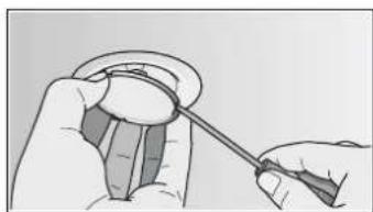

- Insert bulb cover.
- Insert mains plug or switch on fuse again.
Replacing filament bulbs
- Lift bulb cover slightly and push towards the outside of the appliance.
- Unscrew bulb and replace with bulb of the same type.


- Insert bulb cover.
- Insert mains plug or switch on fuse again.
LED lights
Defective LED lights may be replaced by the manufacturer, his customer service or a qualified technician (electrician) only.

Risk of injury!
due to LED lights of risk group 1. Do not look directly into the switched on LED lights for longer than 100 seconds.
Installation instructions


■ This appliance is installed on the wall. ■ Follow the enclosed installation instructions for additional special accessories (e.g. for circulating-air mode). ■ The surfaces of the appliance are sensitive. Avoid damaging them during installation.
Safety notes
⚠ Mortal danger, risk of intoxication!
Due to combustion gases sucked back in. Never operate the appliance in the exhaust air mode at the same time as a room air-dependent heat-producing appliance unless an adequate supply of fresh air is ensured.

Room air-dependent heat-producing appliances (e.g. gas, oil, wood or coal-operated heaters, continuous flow heaters or water heaters) obtain combustion air from the room in which they are installed and discharge the exhaust gases into the open through an exhaust gas system (e.g. a chimney).
In combination with an activated vapour extractor hood, room air is extracted from the kitchen and neighbouring rooms - a partial vacuum is produced if not enough fresh air is supplied. Toxic gases from the chimney or the extraction shaft are sucked backed into the living space.
■ Adequate incoming air must therefore always be ensured. ■ An incoming/exhaust air wall box alone will not ensure compliance with the limit.
Safe operation is possible only whenever the partial vacuum in the place where the firing equipment is installed does not exceed 4 Pa (0.04 mbar). This can be achieved whenever the air needed for combustion is able to enter through openings that cannot be sealed, for example in doors, windows, incoming/exhaust air wall boxes or by other technical means.

In any case, consult your responsible chimney sweep. He is able to assess the house's entire ventilation setup and will suggest the suitable ventilation measures to you.
Unrestricted operation is possible if the vapour extractor hood is operated exclusively in the recirculation mode.
Risk of fire!
from flying sparks. Do not install appliance above a solid fuel heater (e.g. wood or coal) unless a closed, non-removable cover is available.
For the installation observe the currently valid building regulations and the regulations of the local electricity and gas suppliers.
Risk of electric shock!
from damaged connection cable. Do not kink or pinch connection cable during installation.
Risk of injury!
From sharp edges during installation. Always wear protective gloves while installing the appliance.
Risk of injury!
from a falling appliance. All safety screws and safety caps must be firmly fitted.
Pipe dimensions
Note: The device manufacturer does not assume any warranty for complaints attributable to the pipe section.
■ The device achieves its optimum performance by means of a short, straight exhaust air pipe and as large a pipe diameter as possible. As a result of long rough exhaust air pipes, many pipe bends or diameters, the optimum extraction performance is not achieved and fan noise is increased. ■ The pipes or hoses for laying the exhaust air line must consist of non-combustible material.
Round pipes
An inner diameter of 150 mm, but at least 120 mm, is recommended.
Flat ducts
The inner cross-section must correspond to the diameter of the round pipes.
∅ 150 mm approx. 177 cm²
∅ 120 mm approx. 113 cm²
■ Flat ducts should have no sharp deflections. ■ Use sealing strip for deviating pipe diameters.
Checking the wall
■ The wall must be level, vertical and adequately load-bearing. ■ The depth of the boreholes must be the same length as the screws. The wall plugs must have a secure grip. ■ The enclosed screws and wall plugs are suitable for solid brickwork. Suitable fasteners must be used for other structures (e.g. plasterboard, porous concrete, poroton bricks). ■ The max. weight of the extractor hood is 40 kg.
Preparing the installation
- Mark a vertical centre line on the wall from the ceiling to the lower edge of the extractor hood.
- Mark positions for the screws and the contour of the attachment area.
- Drill five 8 mm ∅ holes to a depth of 80 mm for the attachments and press in the wall plugs flush with the wall.

Installation
- Screw on the fixing bracket for the flue duct. A

- Screw on brackets for the extractor hood hand-tight, max. 3 N m B

- Screw in threaded pin, leaving it protruding out of the wall by 5–9 mm.

Attaching and aligning the appliance
- Initially remove the protective foil from the back of the appliance and, following installation, remove foil completely.
- When attaching the appliance, ensure that it engages firmly with the brackets.
- Align the appliance horizontally by turning the brackets. If required, the appliance can be moved to the right or left.

Securing the appliance
- Press the safety caps with the arrow upwards onto the brackets until they engage.
- Screw on knurled nut and washer firmly.
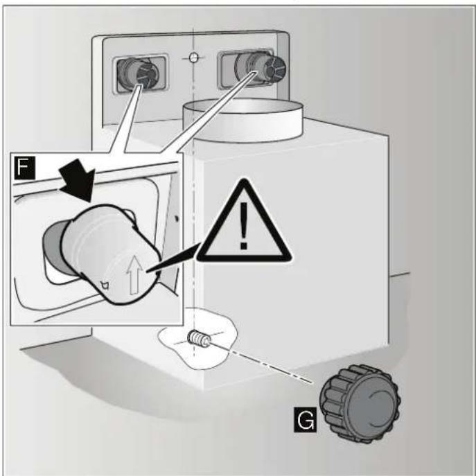
Removing safety caps
If the safety caps have to be removed, use a flat screwdriver.

Connecting the pipes
Note: If using an aluminium pipe, smooth the connection area beforehand.
Exhaust-air pipe ∅ 150 mm (recommended size)
Attach exhaust-air pipe directly to the air-pipe connector and seal.
Exhaust-air pipe ∅ 120 mm
- Attach reducing connector directly to the air-pipe connector.
- Attach exhaust air pipe to the reducing connector.
- Seal both joints appropriately.
Electrical connection
Risk of electric shock!
from damaged connection cable. Do not kink or pinch connection cable during installation.
The required connection data can be found on the rating plate inside the appliance; to do this, remove the metal-mesh grease filter.
Length of the connection cable: approx. 1.30 m
This appliance complies with the EC interference suppression regulations.
This appliance may be connected to a correctly installed earthed socket only.
Attach the earthed socket preferably inside the flue duct.
The earthed socket should be connected via its own circuit. If the earthed socket is no longer accessible following installation of the appliance, a disconnector must be fitted as for a permanent connection.
If a permanent connection is required, the installation must feature an all-pole disconnector (circuit breakers, fuses and contactors) with a min. 3 mm contact opening.
The permanent connection may be installed by an electrician only.
Attaching flue duct
Risk of injury!
From sharp edges during installation. Always wear protective gloves while installing the appliance.

- Separate the flue ducts. To do this, remove the adhesive tape.
- Remove the protective foil from both flue ducts.
- Push one flue duct into the other.
Notes
■ To prevent scratches, place paper for protection over the edges of the outer flue duct. - Slots of the inner flue duct downwards.
- Place flue ducts on the appliance.
- Push inner flue duct upwards and attach to the fixing brackets on the left and right. A
- Press flue duct downwards until it engages. B
- Screw flue duct to the sides of the fixing bracket using two screws. C

- TABLE OF CONTENTS
- ⚠️ SAFETY INSTRUCTIONS
- GENERAL INFORMATION
- WITH EDGE EXTRACTION DUCT
- INSTALLING THE METAL MESH GREASE FILTER
- SECURING THE APPLIANCE
- CONNECTING THE DUCT
- EN
- SAFETY INSTRUCTIONS
- DANGER OF SUFFOCATION
- E-NR. FD
- INSTALLATION
- MORTAL DANGER, RISK OF INTOXICATION
- RISK OF FIRE
- CAUTION
- RISK OF ELECTRIC SHOCK
- RISK OF FIRE, RISK OF INJURY
- RISK OF INJURY
- USING THE APPLIANCE
- RISK OF BURNS
- RISK OF INJURY, RISK OF DAMAGE
- RISK OF FIRE, RISK OF BURNS
- RISK OF BURNS, RISK OF DAMAGE
- CLEANING AND CARE
- RISK OF BURNS, RISK OF ELECTRIC SHOCK
- MAINTENANCE AND REPAIR
- OPERATING MODES
- EXHAUST AIR MODE
- CIRCULATING-AIR MODE
- OPERATION
- SWITCHING ON FAN: VARIANT
- INTENSIVE SETTING
- SWITCHING ON FAN: VARIANTS 2 AND
- LIGHT
- INSTALLING AND REMOVING FILTER
- ⚠️ RISK OF BURNS, RISK OF ELECTRIC SHOCK
- REMOVING METAL-MESH GREASE FILTER
- WITH EDGE EXTRACTION
- NOTES
- INSTALLING THE METAL-MESH GREASE FILTER
- CLEANING APPLIANCE SURFACE
- CLEANING METAL-MESH GREASE FILTERS
- IN THE DISHWASHER
- BY HAND
- REPLACING BULBS
- REPLACING HALOGEN BULBS
- REPLACING FILAMENT BULBS
- LED LIGHTS
- INSTALLATION INSTRUCTIONS
- SAFETY NOTES
- ⚠ MORTAL DANGER, RISK OF INTOXICATION
- PIPE DIMENSIONS
- ROUND PIPES
- FLAT DUCTS
- CHECKING THE WALL
- PREPARING THE INSTALLATION
- ATTACHING AND ALIGNING THE APPLIANCE
- REMOVING SAFETY CAPS
- CONNECTING THE PIPES
- EXHAUST-AIR PIPE ∅ 150 MM (RECOMMENDED SIZE)
- EXHAUST-AIR PIPE ∅ 120 MM
- ELECTRICAL CONNECTION
- LENGTH OF THE CONNECTION CABLE: APPROX. 1.30 M
- ATTACHING FLUE DUCT
Brand : BOSCH
Model : DWB09E152I
Category : Range hood