
TLP791 - Video projector TOSHIBA - Free user manual and instructions
Find the device manual for free TLP791 TOSHIBA in PDF.

| Product Type | Video Projector |
| Brand | Toshiba |
| Model | TLP791 |
| Display Technology | LCD |
| Native Resolution | XGA (1024 x 768) |
| Brightness | 2500 ANSI lumens |
| Contrast Ratio | 800:1 |
| Lamp Life (Normal Mode) | 2000 hours |
| Lamp Type | UHP 200W |
| Keystone Correction | Vertical ±30° |
| Zoom Ratio | 1.2x manual |
| Inputs | VGA, S-Video, Composite, Audio |
| Dimensions (W x H x D) | 320 x 100 x 250 mm |
| Weight | 3.5 kg |
| Power Consumption | 280W (standby <5W) |
| Noise Level | 35 dB (normal mode) |
| Cleaning | Clean air filter every 100 hours; wipe lens with soft cloth |
| Safety | Do not look directly at lens; ensure ventilation; unplug when not in use |
| Spare Parts | Replacement lamp (model: TLPLMP02), remote control, air filter |
| Reparability | Lamp and filter user-replaceable; other repairs by qualified technician |
Frequently Asked Questions - TLP791 TOSHIBA
User questions about TLP791 TOSHIBA
0 question about this device. Answer the ones you know or ask your own.
Ask a new question about this device
Download the instructions for your Video projector in PDF format for free! Find your manual TLP791 - TOSHIBA and take your electronic device back in hand. On this page are published all the documents necessary for the use of your device. TLP791 by TOSHIBA.
USER MANUAL TLP791 TOSHIBA
natural_image
Line drawing of a projector with ventilation slots and control panel (no text or symbols)TLP790
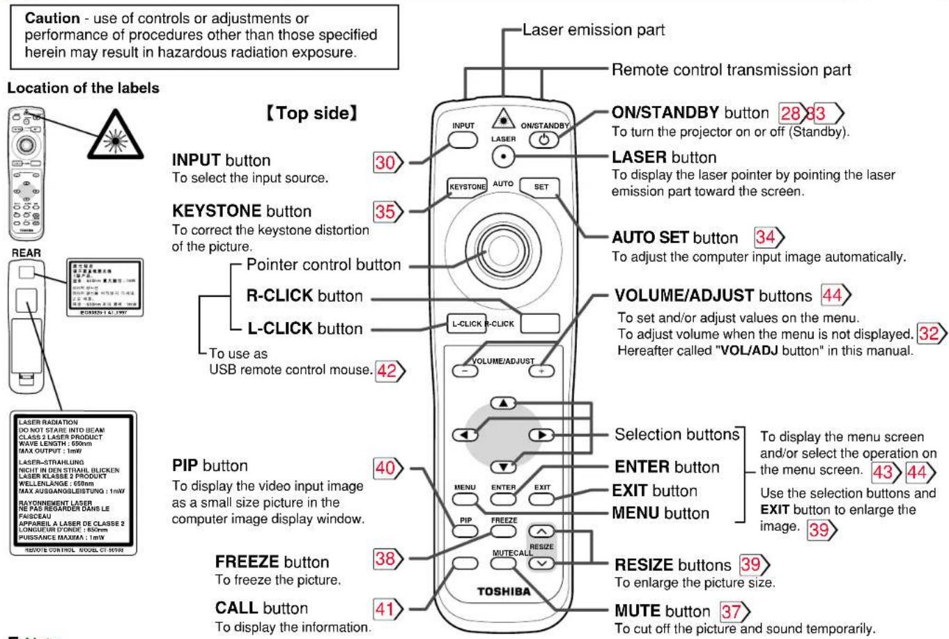
SAFETY PRECAUTIONS

| WARNING:RETURN ON LANDING PLEASE READDIRECTIONS, MEATINGS.DO NOT REMOOLS SCHEANS EXCEPTLAMP COVER SECREWS.DO NOT BLOCK VENTING OPENINGS. | THIS CODE COMPLIERS ARE PART OF THE ROLLER'S,ORIN AN ON A BHAUNT TO THE ROLLAR THIS CODE IS PERTHE ROLLAR PROCESSED BY: 100% OR 100% MAXIMUM ORDER NO. 20000000000000000000000000000000000000000000000000000000000000000000000000000000000000000000000000000 |
| AVIS:YUMULIZE LIME LE MODE D'EMPLOYMENTUSAGE.NE PAS RETIREN LES HA 1A CECEPTIONTRE VA 1A COVERAGE LE AMPLE.NE BOUZZALE PASES OBRICULE DOVENTILATION. | THIS CODE COMPLIERS ARE PART OF THE ROLLAR PROCESSED BY: 100% OR 100% MAXIMUM ORDER NO. 20000000000000000000000000000000000000000000000000000000000000000000000000 |
| 警告:· 使用になるのに,取総態明確をお読みください。· プレープかー出倒のまジを取るのかきいください。· 遵化性するさきないください。 | WARNING:YOUNUM LETATE ZIE REDONING/ANLE FUNGLESEN.KELINE SCHWAMEN AUZDER DENLAMPFENZERGLINWAISCH TENTHEVEN.LUFT DORMS/TWINNING NOT BLOCK ENHORN. |
| 警告:操作前,请勿注明需要清除所有,请勿重新启动按钮(灯嘴或额外)添加需要清除关闭允许内部温度调节高导放放磁压穴.23553839 |

The lightning flash with arrowhead symbol, within an equilateral triangle, is intended to alert the user to the presence of uninsulated “dangerous voltage” within the product’s enclosure that may be of sufficient magnitude to constitute a risk of electric shock to persons.

The exclamation point within an equilateral triangle is intended to alert the user to the presence of important operating and maintenance (servicing) instructions in the literature accompanying the appliance.
WARNING: TO REDUCE THE RISK OF FIRE OR ELECTRIC SHOCK, DO NOT EXPOSE THIS APPLIANCE TO RAIN OR MOISTURE. DANGEROUS HIGH VOLTAGES ARE PRESENT INSIDE THE ENCLOSURE. DO NOT OPEN THE CABINET. REFER SERVICING TO QUALIFIED PERSONNEL ONLY.
WARNING: Handling the cord on this product or cords associated with accessories sold with this product, will expose you to lead, a chemical known to the State of California to cause birth defects or other reproductive harm. Wash hands after handling.
FCC Radio Frequency Interference Statement
Note: This equipment has been tested and found to comply with the limits for a USA only Class A digital device, pursuant to part 15 of the FCC Rules. These limits are designed to provide reasonable protection against harmful interference when the equipment is operated in a commercial environment. This equipment generates, uses, and can radiates radio frequency energy and, if not installed and used in accordance with the instruction manual, may cause harmful interference to radio communications. Operation of this equipment in a residential area is likely to cause harmful interference in which case the user will be required to correct the interference at his own expense.
WARNING: Changes or modifications made to this equipment, not expressly approved by USA only Toshiba, or parties authorized by Toshiba, could void the user's authority to operate the equipment.
Notice: This Class A digital apparatus complies with Canadian ICES-003.
WARNING: This is a Class A product. In a domestic environment this product may cause radio interference in which case the user may be required to take adequate measures.
IMPORTANT PRECAUTIONS
CONTENTS
3
Save Original Packing Materials
The original shipping carton and packing materials will come in handy if you ever have to ship your LCD projector. For maximum protection, repack the set as it was originally packed at the factory.
Avoid Volatile Liquid
Do not use volatile liquids, such as an insect spray, near the unit. Do not leave rubber or plastic products touching the unit for a long time. They will mar the finish.
Moisture Condensation
Never operate this unit immediately after moving it from a cold location to a warm location. When the unit is exposed to such a change in temperature, moisture may condense on the crucial internal parts. To prevent the unit from possible damage, do not use the unit for at least 2 hours when there is an extreme or sudden change in temperature.
Exemption Clauses
- Toshiba Corporation bears no responsibility in the case of damages arising from earthquakes, fire not liable to Toshiba Corporation, operating by third parties, other accidents, or use under abnormal conditions including erroneous or improper operation and other problems.
- Toshiba Corporation bears no responsibility for incidental damages (lost profit, work interruption, corruption or loss of the memory contents, etc.) arising from the use of or the inability to use this unit.
- Toshiba Corporation accepts no liability whatsoever for any damages arising from not having followed the descriptions in this Owner's Manual.
- Toshiba Corporation accepts no liability whatsoever for any damages arising from malfunctions arising from combination with equipment or software that is not related to Toshiba Corporation.
In the spaces provided below, record the Model and Serial No. located at the bottom of your LCD projector.
Model No. ____ Serial No.
Retain this information for future reference.
IMPORTANT SAFETY INSTRUCTIONS
CONTENTS
4
CAUTION: PLEASE READ AND OBSERVE ALL WARNINGS AND INSTRUCTIONS GIVEN IN THIS OWNER'S MANUAL AND THOSE MARKED ON THE UNIT. RETAIN THIS BOOKLET FOR FUTURE REFERENCE.
This set has been designed and manufactured to assure personal safety. Improper use can result in electric shock or fire hazard. The safeguards incorporated in this unit will protect you if you observe the following procedures for installation, use and servicing. This unit is fully transistorized and does not contain any parts that can be repaired by the user.
DO NOT REMOVE THE CABINET COVER, OR YOU MAY BE EXPOSED TO DANGEROUS VOLTAGE. REFER SERVICING TO QUALIFIED SERVICE PERSONNEL ONLY.
1. Read Owner's Manual
After unpacking this product, read the owner's manual carefully, and follow all the operating and other instructions.

2. Power Sources
This product should be operated only from the type of power source indicated on the marking label. If you are not sure of the type of power supply to your home, consult your product dealer or local power company. For products intended to operate from battery power, or other sources, refer to the operating instructions.

3. Source of Light
Do not look into the lens while the lamp is on. The strong light from the lamp may cause damage to your eyes or sight.

4. Ventilation
Openings in the cabinet are provided for ventilation and to ensure reliable operation of the product and to protect it from overheating, and these openings must not be blocked or covered. The openings should never be blocked by placing the product on a bed, sofa, rug or other similar surface. This product should not be placed in a built-in installation such as a bookcase or rack unless proper ventilation is provided or the manufacturer's instructions have been adhered to.

Continued

IMPORTANT SAFETY INSTRUCTIONS (continued)

5
5. Heat
The product should be situated away from heat sources such as radiators, heat registers, stoves, or other products (including amplifiers) that produce heat.
7. Cleaning
Unplug this product from the wall outlet before cleaning. Do not use liquid cleaners or aerosol cleaners. Use a damp cloth for cleaning.

9. Overloading
Do not overload wall outlets; extension cords, or integral convenience receptacles as this can result in a risk of fire or electric shock.

6. Water and Moisture
Do not use this product near water – for example, near a bath tub, wash bowl, kitchen sink, or laundry tub; in a wet basement; or near a swimming pool and the like.

8. Power-Cord Protection
Power-supply cords should be routed so that they are not likely to be walked on or pinched by items placed upon or against them, paying particular attention to cords at plugs, convenience receptacles, and the point where they exit from the product.

10. Lightning
For added protection for this product during storm, or when it is left unattended and unused for long periods of time, unplug it from the wall outlet. This will prevent damage to the product due to lightning and power-line surges.

Continued

IMPORTANT SAFETY INSTRUCTIONS (continued)

6
11. Object and Liquid Entry
Never push objects of any kind into this product through openings as they may touch dangerous voltage points or short-out parts that could result in a fire or electric shock. Never spill liquid of any kind on the product.
12. Do not place the product vertically
Do not use the product in the upright position to project the pictures at the ceiling, or any other vertical positions. It may fall down and dangerous.
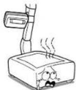
natural_image
Cartoon illustration of a computer monitor with arms and legs, showing a smiling face and dynamic motion (no text or symbols)13. Stack Inhibited
Do not stack other equipment on this product or do not place this product on the other equipment.
Top and bottom plates of this product develops heat and may give some undesirable damage to other unit.
14. Attachments
Do not use attachments not recommended by the product manufacturer as they may cause hazards.
15. Accessories
Do not place this product on an unstable cart, stand, tripod, bracket, or table. The product may fall, causing serious injury to a child or adult, and serious damage to the product. Use only with a cart, stand, tripod, bracket, or table recommended by the manufacturer, or sold with the product. Any mounting of the product should follow the manufacturer's instructions, and should use a mounting accessory recommended by the manufacturer.
A product and cart combination should be moved with care. Quick stops, excessive force, and uneven surfaces may cause the product and cart combination to overturn.

IMPORTANT SAFETY INSTRUCTIONS (continued)

7
16. Damage Requiring Service
Unplug this product from the wall outlet and refer servicing to qualified service personnel under the following conditions:
a) When the power-supply cord or plug is damaged.
b) If liquid has been spilled, or objects have fallen into the product.
c) If the product has been exposed to rain or water.
d) If the product does not operate normally by following the operating instructions. Adjust only those controls that are covered by the operating instructions as an improper adjustment of other controls may result in damage and will often require extensive work by a qualified technician to restore the product to its normal operation.
e) If the product has been dropped or damaged in any way.
f) When the product exhibits a distinct change in performance – this indicates a need for service.
17. If glass components, including lens and lamp, should break, contact your dealer for repair service.
This product incorporates glass components, including a lens and a lamp. If such parts should break, please handle with care to avoid injury and contact your dealer for repair service. The broken pieces of glass may cause to injury.
In the unlikely event of the lamp rupturing, thoroughly clean the area around the projector and discard any edible items placed in that area.
18. Servicing
Do not attempt to service this product yourself as opening or removing covers may expose you to dangerous voltage or other hazards. Refer all servicing to qualified service personnel.

19. Replacement Parts
When replacement parts are required, be sure the service technician has used replacement parts specified by the manufacturer or have the same characteristics as the original part. Unauthorized substitutions may result in fire, electric shock, or other hazards. (Replacement of the lamp only should be made by users.)
20. Safety Check
Upon completion of any service or repairs to this product, ask the service technician to perform safety checks to determine that the product is in proper operating condition.

Continued

IMPORTANT SAFETY INSTRUCTIONS (continued)

8
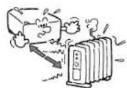
- Do not get your hands between the camera arm and the main unit when setting the camera arm back in its original position.
To avoid injury, be careful not to get your hands caught when setting the camera arm back in its original position. Families with children should be particularly careful.
- Do not leave documents on the unit for long periods of time while using the document imaging function.
Do not leave texts, papers or other documents for projection on the unit for long periods of time. The heat could erase the letters on a thermal paper.
- Do not look into the arm light while it is lit.
The strong light may cause damage to your eyes or sight.
- Do not carry by the camera arm.
Do not carry the projector by the camera arm.
Doing so can result in damage or injury.
- Do not move the projector while the arm is still erect.
Always store the arm back in position when moving the projector. Otherwise injury or damage may result.


natural_image
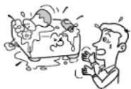
Cartoon illustration of a man reacting to a box with an angry expression (no text or symbols present)Power supply cord selection
CONTENTS
9
If your line voltage is 220 to 240V, use one of the following types of cable.
| Plug configuration Plug type | Line voltage | |
 | EURO240V10 – 15A | 220 – 240V |
| UK240V6A | 200 – 240V | |
| Australian240V10A | 200 – 240V | |
| North American240V15A | 200 – 240V | |
 | Switzerland240V6A | 200 – 240V |
Plug
| configuration Plug type | Line voltage | |
 | EURO | 220 – 240V |
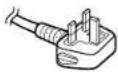 | UK | 220 – 240V |
Use a 5A fuse which is approved by ASTA or BSI to BSI362.
Always replace the fuse cover after changing the fuse.
Contents

Before use
SAFETY PRECAUTIONS 2
IMPORTANT PRECAUTIONS 3
IMPORTANT SAFETY INSTRUCTIONS 4
Power supply cord selection 9
Contents 10
Names of each part on the main unit.... 11
Names of each part on the remote control 14
Loading batteries 15
Remote control operation 16
Installation and connections
Floor-mounted projector placement.... 17
Projector placement angle adjustment 20
Ceiling-mounted projector placement 21
Connecting a computer (COMPUTER IN 1 connector) ... 22
Connecting a computer (COMPUTER IN 2 connector) .. 23
Connecting video equipment 24
Projector operation control by a computer 26
How to use the output connector 27
Operations
Projection on the screen.... 28
Turning the power off 33
Adjusting the picture automatically.... 34
Correcting the keystone distortion 35
Cutting off the picture and sound temporarily .... 37
Freezing the picture 38
Enlarging the picture size 39
Displaying PIP Sub-pictures 40
Displaying Information.... 41
Operating a computer by the remote control 42
Adjustments & Settings
Operating the menu screen 43
GUIDE MENU adjustments and settings 45
FULL MENU adjustments and settings - Picture 46
FULL MENU adjustments - Position 47
FULL MENU adjustments - Color 48
FULL MENU adjustments and settings - Audio 49
FULL MENU adjustments and settings - Display 50
FULL MENU settings - Default setting 51
FULL MENU settings - Reset 52
PIP menu setting 53
Document imaging camera
Part names (of the document imaging camera model) ... 54
Preparation of the document imaging camera 55
Picture projection with the document imaging camera .. 56
Overlaying projection 59
Locking the white balance 60
Correcting illuminated defects 61
Maintenance
Trouble indications 62
Air filter cleaning 63
Lens and main unit cleaning 65
Lamp replacement 66
Others
Before calling service personal 68
Pin assignment of COMPUTER IN connector 70
Applicable signal 71
Controlling the projector by using RS-232C 73
Specifications 79
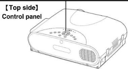
Names of each part on the main unit
CONTENTS
11
CAUTION
Openings in the cabinet are provided for ventilation and to ensure reliable operation of the product and to protect it from overheating, and these openings must not be blocked or covered.
The explanation here is only for the model without the document imaging camera. For the model with the document imaging camera, refer to 54.
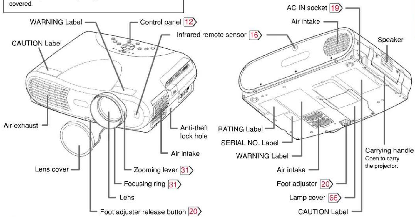
Note
The air exhaust discharges high temperature air. Do not put anything around the air exhaust, otherwise it may deform due to the high temperature air.
Continued

Names of each part on the main unit (continued)
CONTENTS
12
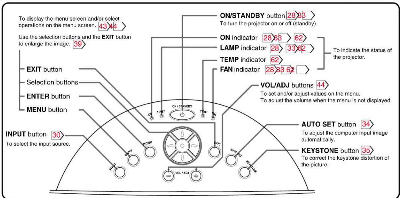
Names of each part on the main unit (continued)

Names of each part on the remote control

Note
The description in the label differs dependent on the destination of the product.
Loading batteries
CONTENTS
15
Notes
Using batteries incorrectly can cause them to leak or burst. Strictly observe the following.
- Install the batteries with their + and - ends facing correctly.
- Do not charge, heat, disassemble, or short the batteries or throw them into a fire.
- Do not leave any exhausted batteries in the remote control.
- Do not mix different types of batteries or new and old batteries.
- When you will not be using the remote control for a prolonged period, take the batteries out of the remote control.
- When the remote control stops working or only works at very close range, replace all the batteries with new ones.
- When replacing the batteries, use longer life alkaline batteries.
- If a battery has leaked, carefully wipe off any residue inside the battery case before loading new batteries.
1
【Bottom side】
Open the cover.
2
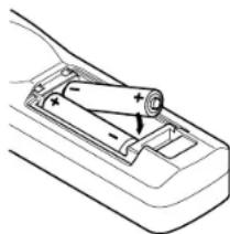
natural_image
Diagram of a car's internal battery compartment with an arrow indicating direction (no text or labels)Install the batteries.
Make sure that the +/- polarities match the illustration in the compartment.
Two batteries (LR6 (SIZE AA)) are used.
3
natural_image
Line drawing of a mechanical component with an arrow indicating direction (no text or symbols)Attach the cover.
Remote control operation
CONTENTS
Point the remote control at the infrared remote sensor and press a button.
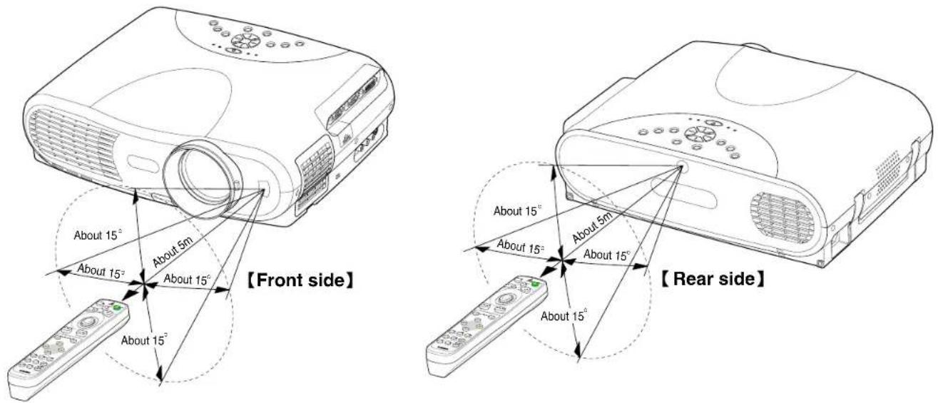
Notes
• The remote control may not operate when there is sunlight or other strong light such as a fluorescent lamp shining on the projector's remote sensor.
- Operate the remote control from a position where the remote sensor is visible.
- Do not drop the remote control or otherwise jolt it.
- Keep the remote control out of locations with excessively high temperature or humidity.
- Do not get water on the remote control or place wet objects on it.
- Do not disassemble the remote control.
- Under unusual circumstances the remote control may not operate well due to the location being used or the surroundings.
At such times, change the direction of the remote control to the projector and retry the operation.
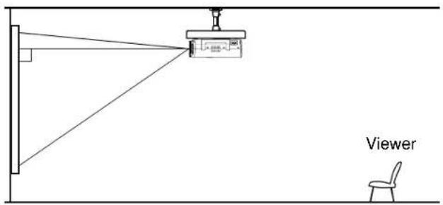
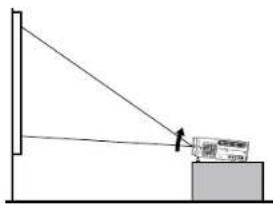
Floor-mounted projector placement

17
There are two ways to place the floor-mounted projector. Perform the "Projection mode" setting on the menu screen for the projection method. 51
For the ceiling-mounted projector placement, refer to the page 21.
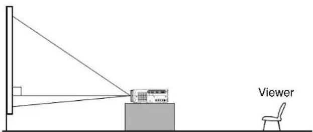
Floor-mounted front projection
Viewing a picture projected on the front of the screen from a floor installation.
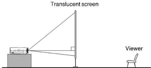
Floor-mounted rear projection
Viewing a picture projected through the back of the screen from a floor installation.
Floor-mounted projector placement (continued)

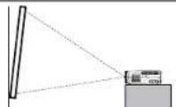
1 Place the projector on a steady, level surface such as a table.
To obtain proper screen projection, place the projector so that the light beam hits the screen squarely.
Point the lens straight at the center of the screen as above.
Place the projector horizontally so that the projecting light hits the screen squarely.
2 Determine the screen size projected on the screen.
The projection size depends on the distance between the lens and the screen.
Adjust the projection size by changing the distances as shown below.
$$ \begin{array}{l} a (\min.) = \frac {\text { Projection size } - 1 . 7 3 8 2}{2 3 . 3 7 7} \ a (\max.) = \frac {\text { Projection size } - 1 . 3 7 6 6}{2 3 . 2 6 6} \ b = \text { Projection size (cm) } \times 0. 0 7 2 \ \end{array} $$
a: Distance between the lens and the screen (m)
b: Distance between the lens height and the bottom of projection area (cm)
• The values are approximations.
| Projection size (inches) | a (m) | b (cm) | |
| Minimum (At maximum zoom) | Maximum (At minimum zoom) | ||
| 32 (81) | - | 1.30 | 5.8 |
| 40 (102) | 1.30 | 1.66 | 7.3 |
| 60 (152) | 1.98 | 2.52 | 11.0 |
| 80 (203) | 2.66 | 3.38 | 14.6 |
| 100 (254) | 3.34 | 4.24 | 18.3 |
| 150 (381) | 5.05 | 6.39 | 27.4 |
| 200 (508) | 6.75 | 8.54 | 36.6 |
| 300 (762) | 10.15 | - | 54.9 |
Floor-mounted projector placement (continued)

3
Connect the power cord.
- Insert one end into the AC IN socket on the projector.
- Insert the other end into a wall outlet.
The three indicators, TEMP, LAMP, and ON, light in green for several seconds and then the ON indicator lights in orange and the projector turns to the standby mode.
Do not perform any operations while the three indicators are lit green.
4
Take off the lens cover.
natural_image
Diagram of a device with a blue circular component inserted into a ring, showing no text or symbols.Notes
- When the projector is moved from a cold location to a warm location, or when the ambient temperature in the projection room has risen suddenly, moisture may condense on the lens or the internal optical section to blur the projected pictures. In such a case, leave the projector for an adequate time (1 to 2 hours, depending on the room's condition) before using it, so it adjusts to the ambient temperature.
- If the screen is exposed to direct sunlight or other strong light, the projected picture will become too faint to see. Shut out the light with curtains or by other means.
- If the screen and the projector are not installed properly, the projected picture may be distorted.
Projector placement angle adjustment

The tilt of the projector can be adjusted using the foot adjuster.
1
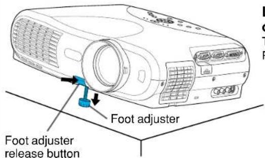
Lift the front of the projector until the desired tilt angle is obtained and hold down the foot adjuster release button.
The foot adjuster will extend.
Release the button to lock in position.
2
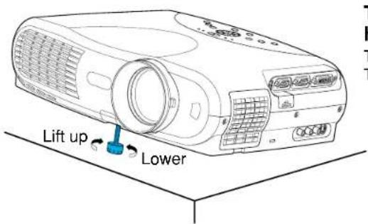
Turn the foot adjuster to make fine adjustment to the height.
Turn clockwise to lift up.
Turn counterclockwise to lower.
Notes
- To put the foot adjuster back, hold down the foot adjuster release button and lower the front slowly.
- Be sure to hold the projector when putting the foot adjuster back so as not to let the front fall on your fingers.
- Do not tilt the projector at an angle exceeding the range adjustable by the foot adjusters, since the life duration of the lamp may be shortened.
Ceiling-mounted projector placement

CAUTION
When a ceiling mount is required, please consult with the dealer.
Ceiling-mounted front projection
Viewing a picture projected on the front of the screen from a ceiling installation.
Ceiling-mounted rear projection
Viewing a picture projected through the back of the screen from a ceiling installation.
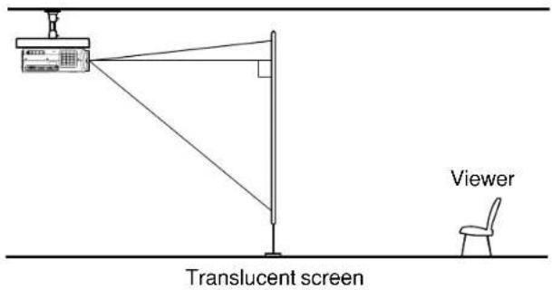
Perform the "Projection mode" setting on the menu screen for the projection method. 51
Note
The relation between the projection size and the distance to the screen is the same as that of the floor-mounted projection mode 18.
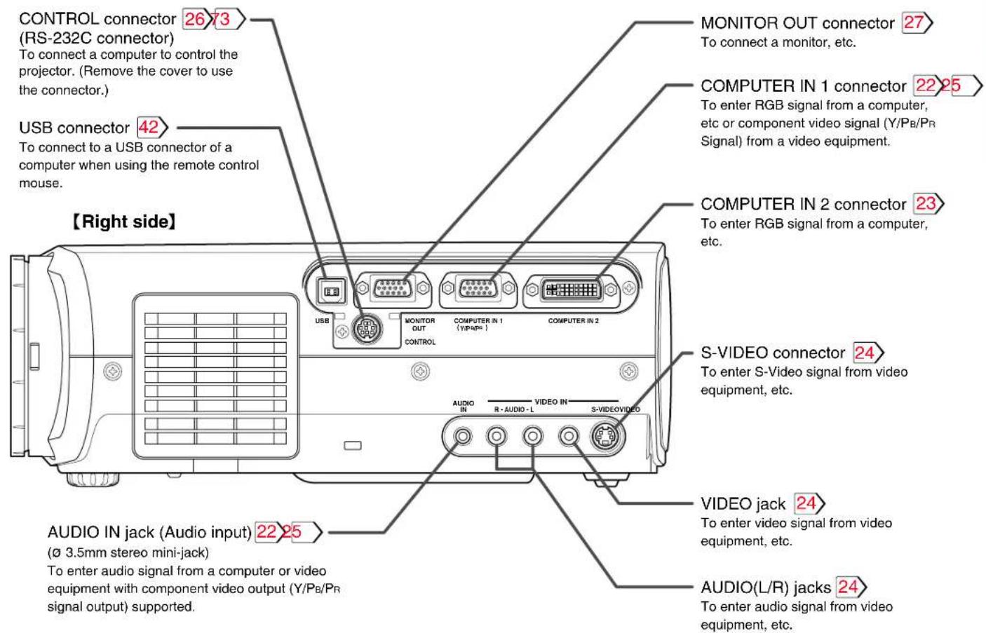
Connecting a computer (COMPUTER IN 1 connector)

You can project the picture from the computer.
Check that the power supplies for the projector and for the computer are off before connecting the cables.
Notes
• The projector cannot be connected to a computer without an analog RGB connector. For details, refer to the computer manual.
- You may not be able to connect some computers to the projector. For details, consult the dealer.
- Some computers may have output modes which are not compatible with this projector. Check the compatibility of the connectors, signal levels, timing, resolutions, etc.
Connecting a computer (COMPUTER IN 2 connector)

You can project the picture of analog RGB or digital RGB signal from a computer by using the COMPUTER IN 2 connector. Check that the power supplies for the projector and for the computer are off before connecting the cables.
Notes (Please also read "Notes" on page 22.)
- DVI digital cable needs to be purchased separately when you input a digital RGB signal.
- Although infrequent, noise might be generated on the screen depending on the types of computer and connection cables. Should this occur, reduce the refresh rate of the computer signal, or lower the resolution. Use of connection cables that are 2 m or shorter is recommended.
- The input signal specifications of the DVI port of the projector conform to DVI 1.0 specifications; however, contents protection is not supported. Note that there is no guarantee for the operations not specified in this specification.
Connecting video equipment

24
You can project the picture from video equipment by using VIDEO IN connectors.
Check that the power supplies for the projector and for the video equipment are off before connecting the cables.

The S-VIDEO connector and VIDEO jack can be used independently, but the audio input jacks are used as both the S-VIDEO and VIDEO input.
Continued

Connecting video equipment (continued)

You can project the picture from video equipment with component video output jack.
Check that the power supplies for the projector and for the video equipment are off before connecting the cables.
Projector operation control by a computer

You can control the projector by a computer connected with the control cable supplied. 73 Check that the power supplies for the projector and for the computer are off before connecting the cables.
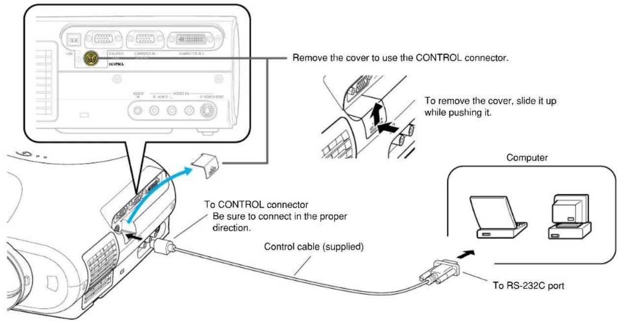

Do not connect any cable other than the exclusive one supplied.
How to use the output connector

You can output video signals to a computer monitor, etc.
Check that the power supplies for the projector and for the equipments are off before connecting the cables.
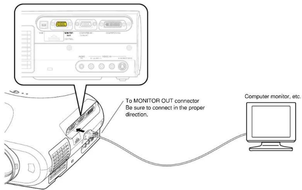
Notes
- The analog RGB signals or Y/Pb/Pr signals of the COMPUTER IN 1 or COMPUTER IN 2 connector selected by the input select operation are output from the MONITOR OUT connector. If neither of these input sources is selected, the signal of the COMPUTER IN 1 connector is output. (Digital RGB signals are not output.)
- Signals are output from the MONITOR OUT connector even when in the standby mode.
- An ordinary computer monitor may not display a normal picture with Y/P B/PR signals.
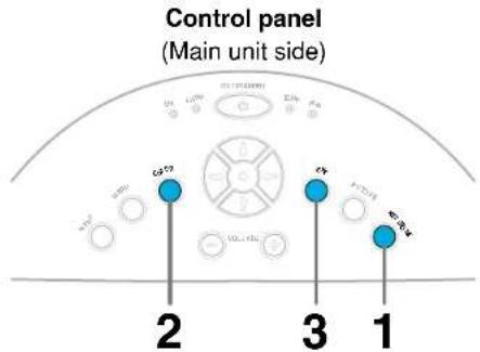
Projection on the screen
CONTENTS
28
CAUTION – Do not look into the projection lens while operating the projector.
Remote control
Control panel
Preparation
1 Install and connect the projector properly.
② Take off the lens cover.
1
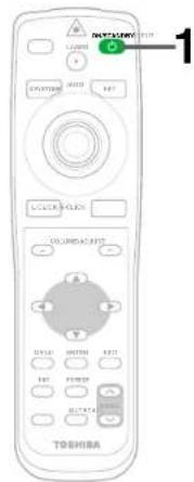
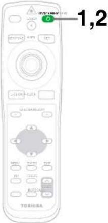
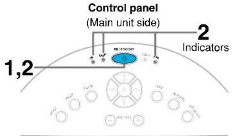
ON/STANDBY
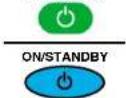
Press ON/STANDBY.
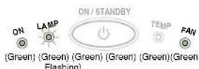
The projector turns on and the ON, LAMP and FAN indicators light in green.
(The LAMP indicator blinks while the lamp is warming up.)


The lamp lights and the start up display appears.
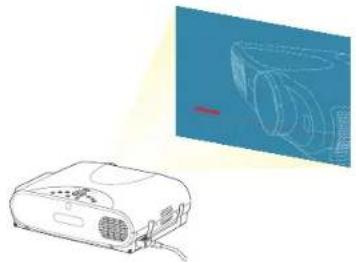
natural_image
Illustration of a projector and its internal components, shown in line and perspective views (no text or symbols)Notes
- The startup screen disappears when you push the EXIT button or wait for a while. You can also set the startup screen not to be displayed on the menu screen. 51
- When a projector is used for the first time, the language selection menu is displayed after the startup screen disappears. Set it up with procedures 2 and 3 on the next page.
Projection on the screen (continued)

29
Remote control
Control panel
(Main unit side)
When a projector is used for the first time, the language selection menu, which is to select a language for displaying menus or messages, is displayed. Select a desired language. (At shipping from factory, it is set to English.)
flowchart
graph LR
    A["Input Block 1"] --> B["Arrow"]
    C["Input Block 2"] --> D["Arrow"]
    E["ENTER"] --> F["ENTER"]
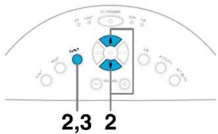
Select a desired language with the selection buttons (▲/▼), and press ENTER.
A menu confirming the selection result is displayed in the selected language.
Press ENTER to confirm.
Press EXIT to return to step 2 if you want to re-select a language.
Notes
- The language selection menu will not be displayed on the second and subsequent times you turn on the power. However, if "Reset all" 52 is executed, the language selection menu will be displayed when the power is turned on next.
• The language can also be selected on the menu screen. 50 - This Owner's manual is described on the supposition that English was selected.

Turn on the connected equipment and put it in playback mode.
Select "Cancel" or install driver contained in the supplied CD-ROM, when the dialog box of the Add New Hardware Wizard screen appears on the computer when connecting a computer. (The supplied CD-ROM contains a driver information file named TOSHIBA_TLP.inf. Click the Browse button of the dialog box to find and designate this file.)
Continued

Projection on the screen (continued)

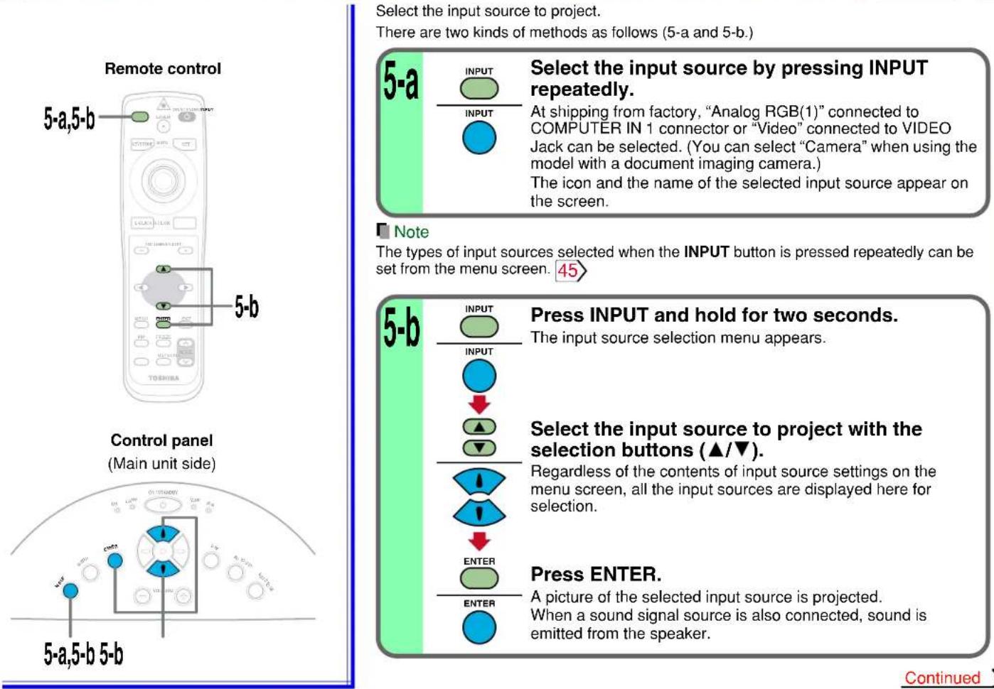
Select the input source to project.
There are two kinds of methods as follows (5-a and 5-b.)
Select the input source by pressing INPUT repeatedly.
At shipping from factory, "Analog RGB(1)" connected to COMPUTER IN 1 connector or "Video" connected to VIDEO Jack can be selected. (You can select "Camera" when using the model with a document imaging camera.)
The icon and the name of the selected input source appear on the screen.
Note
The types of input sources selected when the INPUT button is pressed repeatedly can be set from the menu screen. 45
Press INPUT and hold for two seconds.
The input source selection menu appears.
Select the input source to project with the selection buttons (▲/▼).
Regardless of the contents of input source settings on the menu screen, all the input sources are displayed here for selection.
Press ENTER.
A picture of the selected input source is projected. When a sound signal source is also connected, sound is emitted from the speaker.
Continued

Projection on the screen (continued)

31
Notes
(Signal sent from the computer)
- If you project an image from a computer with an LCD screen while monitoring the image on the computer, the image may not be projected properly, depending on the computer model. In this case, turn off the computer display. For details on controlling the computer display, etc., refer to the computer's manual and description on the software for the computer used.
- The projector projects an image by XGA signal (1024 x 768) in full screen.
- The image quality from a computer signal other than XGA may be inferior. It is recommended to set the external monitor connected to the computer to XGA mode (1024 x 768).
- The projector can be also applied to DDC2B (Display Data Channel 2B). If your computer is applied to the DDC, start up your computer after turning on the projector.
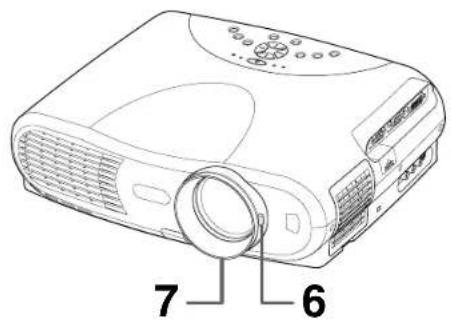
6

Adjust the picture size by turning the zooming lever.
Turn to the right to enlarge the picture.
Turn to the left to reduce the picture.
7

Focus on the picture by turning the focusing ring.
A still picture is recommended for focusing.
Projection on the screen (continued)

Remote control
Control panel
(Main unit side)
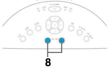
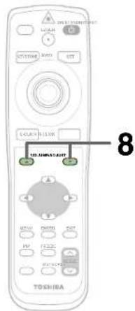
8
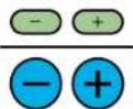
Press VOL/ADJ (+/-) to adjust volume.
Press the (+) button to increase volume. Press the (-) button to decrease volume.
Notes
• To change the projecting angle, adjust the foot adjuster. 20
- If the screen image suffers keystone distortion, press the KEYSTONE button to adjust the distortion. 35
- Due to lamp characteristics, flickers may occasionally occur in a picture. This is not malfunction of the unit.
- The lamp may rarely burst with a loud sound. A lamp is consumable supplies. If used for extended periods, images will appear dark, and the lamp could burn out. This is characteristic of a lamp, and is not malfunction. (The lifetime of the lamp depends on conditions of use.)
- The projector's liquid crystal panel is made using extremely advanced technology, but there may be black spots (pixels that do not light) or bright spots (pixels that are constantly lit) on the panel. Please note that these are not malfunctions.
- When trying to press a button whose operation is not available, the icon appears.
- When supplying the signal not compatible with the projector, the icon appears.
- When signals are not input from the input source, the OFF icon appears.
- The projector may stop operating if the surrounding temperature is too high or if the air filter is clogged with dust. 62
About the LCD Panel
The life of the LCD panel is limited.
Take care over the points below so as to use the panel for years.
- To prolong the life of this panel, never fail to turn the power off when the panel is not in use and make sure that the lamp has gone out. The state of the lamp being extinguished helps enhance the effect of energy saving.
- If the air filter is stained and is clogged up, the main unit inner temperature rises. As a result, the life of the LCD is shortened and a malfunction may also occur. Clean the air filter from time to time 63 and replace it regularly. It is recommended that this replacement be done at the time of replacing a lamp. (Ask a dealer where the unit was purchased or your nearby service station about an air filter for replacement.)
Turning the power off
CONTENTS
33
Remote control
1
ON/STANDBY

ON/STANDBY

Press ON/STANDBY after using the projector.
An instruction message for turning the power off appears on the screen and disappears after a while. When the message disappears, operation becomes invalid.
2
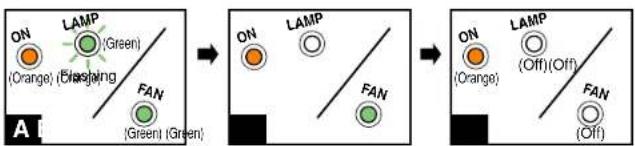
ON/STANDBY

ON/STANDBY

Press ON/STANDBY again.
Cooling starts. Once cooling is completed, the LAMP and FAN indicators turn off and the standby mode is set. (The ON indicator turns in orange.)
flowchart
graph LR
    A["ON (Orange)"] --> B["LAMP (Green)"]
    B --> C["FAN (Green)"]
    C --> D["ON (Orange)"]
    D --> E["LAMP (Green)"]
    E --> F["FAN (Green)"]
    F --> G["ON (Orange)"]
    G --> H["LAMP (Green)"]
    H --> I["FAN (Green)"]
    I --> J["ON (Orange)"]
    J --> K["LAMP (Green)"]
    K --> L["FAN (Green)"]
    L --> M["ON (Orange)"]
    M --> N["LAMP (Green)"]
    N --> O["FAN (Green)"]
    O --> P["ON (Orange)"]
    P --> Q["LAMP (Green)"]
    Q --> R["FAN (Green)"]
    R --> S["ON (Orange)"]
    S --> T["LAMP (Green)"]
    T --> U["FAN (Green)"]
    U --> V["ON (Orange)"]
    V --> W["LAMP (Green)"]
    W --> X["FAN (Green)"]
    X --> Y["ON (Orange)"]
    Y --> Z["LAMP (Green)"]
    Z --> AA["FAN (Green)"]

To protect the light source lamp, the LAMP indicator blinks as long as a minimum of cooling is necessary. The power cannot be turned back on during this time. Unplugging the power cord at this time will shorten the lamp's duration life.

The cooling fan continues to run for a while to expel the heat remaining inside. If you are in a hurry, however, you may unplug the power cord at this time.

The standby mode is set.
Notes
- The projector consumes about 20W of power in the standby mode. We recommend you unplug the power cord when not using the projector for long periods of time.
- Be sure that the LAMP indicator has turned off before unplugging the power cord. Cutting the power by unplugging the power cord while the projector is operating or the light source lamp is being cooled will shorten the lamp's duration life. Should a fault or some other irregularity arise with this unit, unplug the power cord.
- When reinserting the power plug before the lamp has cooled, please wait until the lamp has cooled sufficiently before use. When the lamp is at a high temperature, it may not light and it's life duration will be shortened.
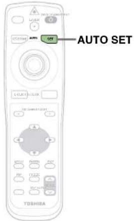
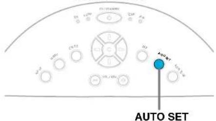
Adjusting the picture automatically

Remote control
Control panel
(Main unit side)
You can adjust the optimum horizontal position, vertical position, sampling phase and sampling frequency for projecting analog RGB signals at the touch of a button.
1
Input full screen video signals from the input source (computer) and project the image.
Adjustments may not be performed properly for images that are not displayed on the entire screen or for extremely dark images.
2
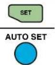
Press AUTO SET.
The horizontal position, vertical position, sampling phase and sampling frequency are adjusted automatically.
The icon 📋 appears during signal processing.
Notes
- Automatic adjustment may not be performed properly for signals other than those computers' signals with which the projector is compatible.
- The horizontal position, vertical position, sampling phase and sampling frequency can also be adjusted from the menu screen 47.
\* Sampling frequency
Analog RGB signals input from the computer are converted into digital signals inside the projector. The sampling frequency is the number of times per second the analog signals are converted into digital signals. In order to capture (sample) each individual dot of the computer's signals, the sampling frequency must be adjusted to match the computer's dot clock frequency. If this adjustment is off, details of the image details may be blurred, a striped pattern may appear if images with many vertical lines are displayed, or the image's width may change. For computer signals with which are projector-compatible, the sampling frequency is adjusted automatically even when the AUTO SET button is not pressed.
\* Sampling phase
The sampling phase is the timing at which the computer's analog RGB signals are sampled. If the sampling phase is off, the individual dots cannot be sampled at the proper timing, resulting in blurred or flickering images.
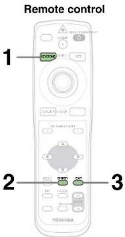
Correcting the keystone distortion

A picture may be expanded on the upper side if projected upward from the projector lifted up by the foot adjuster. The projector can correct this keystone distortion.
natural_image
Simple line drawing of a mechanical setup with a lever and a block, no text or symbols present.
bar_stacked
| Group | SP1.1 | SP1.2 | SP1.3 | |-------|-------|-------|-------| | Tc | 25 | 10 | 25 | | SD | 25 | 10 | 10 | | Tm | 25 | 20 | 20 | | SD | 25 | 20 | 20 |
bar_stacked
| Time Period | IPL 1 | IPL 2 | IPL 3 | | ----------- | ----- | ----- | ----- | | Tn Qtr | 40 | 10 | 25 | | Jnd Qtr | 30 | 15 | 10 | | Knd Qtr | 40 | 20 | 20 | | Kth Qtr | 25 | 30 | 25 |1

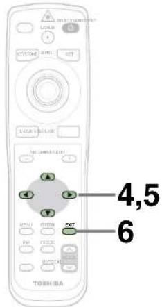
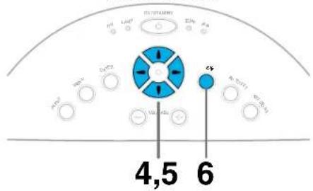
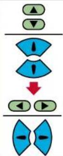
KEYSTONE

Press KEYSTONE.
The keystone adjustment menu appears, with the "Auto. V-keystone" being selected. (This menu is the same as the sub-menu which is displayed when "Correct the keystone distortion of the screen" is selected from GUIDE MENU. 45)
2

ENTER

Press ENTER.
The vertical keystone distortion on the picture projected is automatically corrected.
The icon appears while the keystone correction is executing. When the correction is finished, the menu for selecting "V-keystone" or "H-keystone" by manual adjustment appears, with the former being selected.
3


Confirm the keystone distortion.
When no more adjustment is needed, press the EXIT button repeatedly until the menu disappears. If the keystone distortion has not been corrected properly, adjust it according to the next procedure.
Continued
Correcting the keystone distortion (continued)

Remote control
Control panel
(Main unit side)
4
If the screen is not installed vertically, "Auto. V-keystone" is not corrected properly.
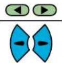
After confirming that "V-keystone" is selected on the menu; Adjust the distortion of the both sides (right and left) of the picture with the selection buttons (◀/▶).
5
flowchart
graph TD
    A["Top Left Triangle"] --> B["Blue funnel shape with Inlet"]
    B --> C["Blue funnel shape with Inlet"]
    C --> D["Red Arrow Down"]
    D --> E["Bottom Left Triangle"]
    E --> F["Blue funnel shape with Right Triangle"]
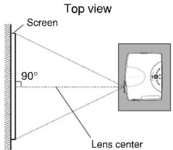
When the projector is not installed at an angle of 90^ to the screen viewed from the top, the upper and lower sides of the projected picture will be distorted.
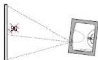
Select "H-keystone" from the menu with the selection buttons (▲/▼), and adjust the distortion of the upper and lower sides of the picture with the selection buttons (◄/►).
6
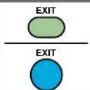
Press EXIT repeatedly until the menu disappears.
The keystone adjustment finishes.
Notes
- Due to digital correction processing, some of the information may be eliminated or the picture quality may be degraded depending on the amount of keystone correction or the contents of the signal source.
- The adjustable range of "V-keystone" or "H-keystone" is influenced by each other's correction amount, and each input signal 71. Therefore, the correction amount may change when switching the input.
- When "Auto. V-keystone" does not operate properly even with the screen installed vertically, execute "Horizontal reference value reset" 52.
Cutting off the picture and sound temporarily

Remote control
The image and sound of this projector can be turned off if you wish to temporarily project the image from another projector or an OHP, etc., onto the screen.

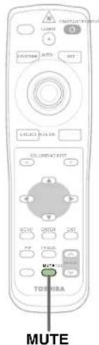
Press MUTE.
The sound and picture are cut off temporarily.
To cancel the mute mode, press MUTE again. The image and sound will be output.
The icon appears in the mute mode.
Note
The mute mode is cancelled if another operation is performed during the mute mode.
Freezing the picture

Remote control
You can freeze the image being projected.
Use this function to stop moving images from a video recorder during presentations.

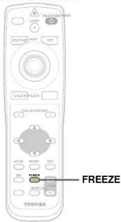
Press FREEZE.
The picture freezes.
To release the picture, press FREEZE again.
The icon appears in the freeze mode.
Notes
- The frozen image can be enlarged with the RESIZE buttons. The freeze mode is cancelled if any operation other than RESIZE is performed.
- The freeze mode cannot be set when there is no input (when no signals are being supplied from a signal source).
- The input source's moving image continues to run even when the projector is set in freeze mode.
- If you use this function on video soft sold on the market, broadcast or broadcast on cable except for the purpose of your private seeing and hearing, it may infringe the copyright protected by the copyright laws.
Enlarging the picture size

You can enlarge (resize) the picture size projected.
Remote control
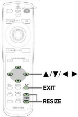
The icon appears in the resize mode.
![RESIZE Press RESIZE (↑) The enlargement ratio increases each time the RESIZE (∧) button is pressed. The enlargement ratio can be increased continuously by keeping the button pressed in. ABCDEFGHIJKL MNOPQRSTUVW XYZ0123456789! #$%&'()[]?<>@' =++ ABCDEFGHIJKL MNOPQRSTUVW YZ0123456789! $%&'()[]?<>@' =++ OPQRSTUV Z012345678 %&'()[]?<>@' ............→123456 '0]0?< RESIZE To reduce the enlargement ratio, press the RESIZE (▼) button. The enlargement ratio can be reduced continuously by keeping the button pressed in. QHST 123456 '0]0?< OPQRSTU 012345678 &'()[]?<>> OPQRSTU Z012345678 %&'()[]?<>> ............→ABCDEFGHIJKL MNOPQRSTUVW XYZ0123456789! #$%&'()[]?<>@' =++ The enlarged section is moved when the selection buttons (▲▼/←) pressed. The section can be moved continuously by keeping the button pressed in. 123456 '0]0?< DEFGH PQRST 123456 HSTUV 3456789 10?<>@ NOT QH Z01234 %&'()[]? EXIT Press the EXIT button to cancel the resize mode and return to the original size.](/content/2026/06/1150525/images/b22fcf2389f7829cc6a73ad621ab9108624319d7249101cec26ac9982c8af9ff.jpg)
Notes
- Enlarged images can be frozen by pressing the FREEZE button. The frozen image can also be enlarged or reduced.
- The resize mode is cancelled if any operation other than setting the freeze mode is performed.
- This projector uses electrical digital resizing, so the picture quality degrades when images are enlarged.
- This function does not work in no input status (no signal is supplied from the signal source).
- If you use this function on video soft sold on the market, broadcast or broadcast on cable except for the purpose of your private seeing and hearing, it may infringe the copyright protected by the copyright laws.
Displaying PIP Sub-pictures

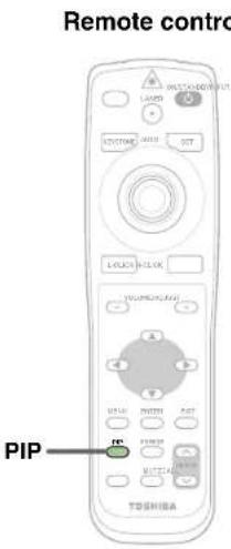
Video or S-video images can be displayed as small images within the computer's image. (Referred to as "sub-pictures" in this manual.)

Press PIP.
A sub-picture is displayed.
Press the PIP button again to turn off the sub-picture.
Notes
- The PIP function cannot be used when a source other than an RGB input source is selected.
- The PIP function cannot be used without signals supplied from an RGB signal source.
- The sub-picture turns off if any other operation is performed.
- The signal source, size, display position and audio input source to display sub-pictures can be changed from the menu screen. 53
- If you use this function on video soft sold on the market, broadcast or broadcast on cable except for the purpose of your private seeing and hearing, it may infringe the copyright protected by the copyright laws.
Displaying Information
CONTENTS
Information on the input signal source, etc., can be displayed.

Press CALL.
The information described below is displayed.
The information display turns off when the CALL button is pressed again.

Status display
Input - current input source
H-resolution - the horizontal resolution of the input signal (at RGB input)
V-resolution - the vertical resolution of the input signal (at RGB input)
H-frequency - the horizontal frequency of the input signal (at RGB input)
V-frequency - the vertical frequency of the input signal (at RGB input)
Sync - the polarity of the sync signal (at RGB input)
Video mode - the color mode of the video signal (at Video, S-Video input)
Signal format- the formatting of the Y/PB/PR signal (at Y/PB/PR input)
Lamp time - the elapsed usage time of the lamp
Version - the version of the firmware
Shutter - the shutter speed of the document imaging camera (at document imaging camera input)
Notes
- The information displayed is not refreshed even if it changes. To refresh the information, turn off the information display, then turn it back on.
• The information display turns off if any other operation is performed. - The "Lamp time" shows an approximate time for lamp replacement. (It should not be used as a lamp warranty time counter.) If the time indicated here nears 1500 hours, contact your store of purchase about obtaining a replacement lamp (TLPL79, sold separately).
- The "Lamp time" can be reset when the lamp is replaced.
- The "Version" is the version of the control program used in the projector and is used for servicing, etc.
Operating a computer by the remote control

You can control a computer by the remote control when the projector and computer are connected with the supplied USB cable. In this manual, this function is explained as "mouse remote control".
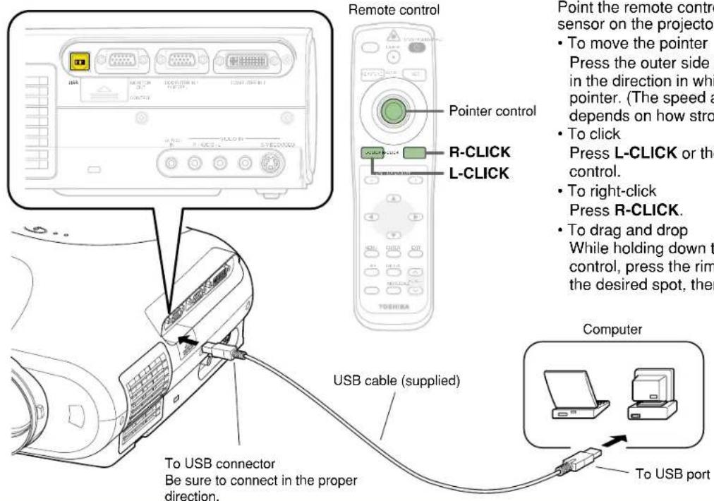
Point the remote control at the remote control
sensor on the projector when operating its buttons.
• To move the pointer
Press the outer side of the pointer control button in the direction in which you want to move the pointer. (The speed at which the pointer moves depends on how strongly the button is pressed.)
- To click
Press L-CLICK or the center of the pointer control.
- To right-click
Press R-CLICK.
- To drag and drop
While holding down the center of the pointer control, press the rim side to move the pointer to the desired spot, then release the center part.
Notes
- This function is available on any computer with the Windows 98/98SE, Windows Me, Windows 2000, Windows XP or Mac OS9 that is equipped with a USB port which can support USB1.1. However, please note that Toshiba does not guarantee the operation of all computers.
- When connecting to the computer's USB port for the first time, a message asking you to insert the Windows98 CD-ROM may appear on the computer's monitor screen, depending on whether or not the device driver is installed. If so, do as the message says.
- When using a USB cable other than the supplied one, be sure to use a shielded type.
Operating the menu screen
CONTENTS
Various adjustments and settings can be made on the menu screen. The basic operations on the menu screen are shown here.

flowchart
graph TD
    A["Start GUIDE MENU: You can adjust or set the functions used frequently."] --> B["Press MENU. The GUIDE MENU appears, and an item list is displayed on the menu."]
    B --> C["Items: Analog R3BT"]
    C --> D["Button operation guide: FULL Item Next Cut"]
    D --> E["Select the item with the selection buttons (▲/▼)."]
    E --> F["Press ENTER to confirm. The selected item can be adjusted or set."]
    F --> G["Adjust and set the selected item with the button displayed in the button operation guide section. According to the selected item, the kind ([adjustment"], [setting] or["execution"]) and the button to be used are displayed in the button operation section.]
    G --> H["Press EXIT to return to the GUIDE MENU. When you want to select other items, press EXIT repeatedly until GUIDE MENU appears. When you want to quit, press EXIT repeatedly until GUIDE MENU disappears."]
    H --> I["End"]

    J["If you want to make more detailed adjustments and settings, call up the FULL MENU. Return to the GUIDE MENU when the MENU button is pressed."] --> K["FULL MENU: For the operating instruction, refer to the next page. 44"]
    K --> L["Press MENU once again. The FULL MENU of [Picture"] appears. FULL_MENU_has_seven_pages_of["Picture"], [Position], [Color], [Audio], [Display], [Default setting] and["Reset"]. Use the selection buttons (◄/►) to change the page of FULL MENU.]
    L --> M["[Picture"] [Position] [Color]]
    M --> N["[Reset"] [Display] [Audio default setting]]
    N --> O["VOL/ADJ"]
    O --> P["VOL/ADJ Selection"]
    O --> Q["VOL/ADJ ENTER"]
    P --> R["VOL/ADJ EXIT"]
    Q --> S["VOL/ADJ EXIT"]
Operating the menu screen (continued)
CONTENTS
44
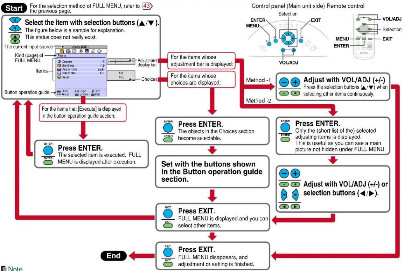
flowchart
graph TD
    A["Start"] --> B["Select the item with selection buttons (▲/▼)."]
    B --> C{If the figure below is a sample for explanation.}
    C -->|Yes| D["Adjustment display bar"]
    C -->|No| E["Adjust the items whose adjustment bar is displayed;"]
    D --> F["For the items whose choices are displayed;"]
    E --> G["For the items whose selection of other items continuously."]
    F --> H["Press ENTER. The objects in the Choices section become selectable."]
    G --> I["Set with the buttons shown in the Button operation guide section."]
    I --> J["Set with the buttons shown in the Button operation guide section."]
    J --> K["Press EXIT. FULL MENU is displayed and you can select other items."]
    K --> L["Press EXIT. FULL MENU disappears, and adjustment or setting is finished."]
    L --> M["End"]
Note
An exclusive menu is displayed when making PIP function sub-picture settings.
GUIDE MENU adjustments and settings

On GUIDE MENU, you can set or adjust the functions frequently used.
| The relationship between input source and item Yes: Adjustable -: Not displayed | ||||||||||
| Adjust the image brightness. | Contrast | ADJ. | Adjust the contrast of the picture. | Yes | Yes | Yes | Yes | Yes | Yes | |
| Brightness | ADJ. | Adjust the brightness of the picture. | ||||||||
| Adjust the image flicker. | Phase | ADJ. | Adjust the flicker of the picture. (Sampling clock phase adjustment) | Yes | Yes | - | - | - | - | |
| Adjust the image color. | Color | ADJ. | Adjust the color depth of the picture. | - | - | - | Yes | Yes | - | |
| Adjust the sensitivity of the document imaging camera. | Camera gain | ADJ. | Adjust the document imaging camera's gain. | - | - | - | - | - | Yes | |
| Shutter | Select a shutter speed below to decrease the flickering of the document imaging camera's picture. | - | - | - | - | - | Yes | |||
| Restrain the flicker of the camera. | Auto | SET | The shutter speed is set automatically. | |||||||
| 50Hz | SET | The shutter speed is fixed to 50 Hz. | ||||||||
| 60Hz | SET | The shutter speed is fixed to 60 Hz. | ||||||||
| Select the image with its brightness priority or quality (color) priority. | Bright The picture is set with its brightness priority.SET | Yes | Yes | Yes | - | - | - | |||
| True color The picture is set with its color quality priority.SET | ||||||||||
| Correct the keystone distortion of the screen. | Auto. V-keystone EXEC. | the vertical keystone distortion automatically. | ADJ.V-keystones (common for all of the inputs) | |||||||
| To manual adjustment EXEC. | Adjust the Vertical keystone. | |||||||||
| H-keystone | Adjust the Horizontal keystone. | ADJ. | ||||||||
| Select the input source when changing the input. | COMPUTER IN 1 | SET | ☑: COMPUTER IN 1 connector is selectable with the INPUT button. | SET | Yes (common for all of the inputs) | |||||
| ●: Use COMPUTER IN 1 connector as Analog RGB RGB input. | ||||||||||
| Y/PB/PR | SET | ●: Use COMPUTER IN 1 connector as Y/PB/PR input. | ||||||||
| COMPUTER IN 2 | SET | ☑: COMPUTER IN 2 connector is selectable with the INPUT button. | ||||||||
| Analog RGB(2) | SET | ●: Use COMPUTER IN 2 connector as Analog RGB (2) input. | ||||||||
| Digital RGB | SET | ●: Use COMPUTER IN 2 connector as Digital RGB input. | ||||||||
| VIDEO: Video input is selectable with the INPUT button.SET | ||||||||||
| S-VIDEO | SET | ☑: S-Video input is selectable with the INPUT button. | ||||||||
| CAMERA | SET | ☑: Camera input is selectable with the INPUT button. | ||||||||
Notes
- The items related to the camera (the document imaging camera) are displayed only with models having a camera.
- "Sampling phase" is adjusted and memorized for each RGB signal 71.
- "Keystone" and "Input source setting" can be adjusted (set) at all input sources, but the adjustments (settings) made at one input source are applied to all input sources.
- It is impossible to exit from the menu if no input source is selected.
- If setting of the input source is changed, the setting becomes effective the next time the input is changed.
- The adjustments or settings made are memorized automatically when the power is turned off by pressing the ON/STANDBY button. If the power cord is unplugged or if a power failure occurs while the projector is on, the adjustments or settings are not memorized.
FULL MENU adjustments and settings - Picture

| You can make various adjustments or settings of the picture from FULL MENU [Picture].To operate FULL MENU, refer to page 44. | The relationship between input source and item Yes: Adjustable : Not displayed | |||||||||
| Analog RGB(1) | Analog RGB(2) | Digital RGB | Y/PB/PH | Video | S-Video | Camera | ||||
| Contrast | ADJ. | Adjust the contrast of the picture. | Yes | Yes | Yes | Yes | Yes | Yes | Yes | |
| Brightness | ADJ. | Adjust the brightness of the picture. | Yes | Yes | Yes | Yes | Yes | Yes | Yes | |
| Sharpness | ADJ. | Adjust the sharpness of the picture. (In Y/Pb/Pr input mode, sharpness is a setting item.) | - | - | - | Yes | Yes | Yes | Yes | |
| Camera gain Adjust | the document imaging camera's gain.ADJ. | - | - | Yes | ||||||
| Picture mode Bright | The picture is set with its brightness priority.SET | Yes | Yes | Yes | - | - | - | - | ||
| True color The picture is set with its color quality priority.SET | ||||||||||
| Video mode Auto. | SET | The video mode (color system) is set automatically. | - | - | - | - | Yes | Yes | - | |
| NTSC | SET | The video mode is fixed to NTSC system. | ||||||||
| PAL | The video mode is fixed to PAL system.SET | |||||||||
| SECAM | SET | The video mode is fixed to SECAM system. | ||||||||
| PAL-N | SET | The video mode is fixed to PAL-N system. | ||||||||
| PAL-M | SET | The video mode is fixed to PAL-M system. | ||||||||
| PAL60 | SET | The video mode is fixed to PAL60 system. | ||||||||
| NTSC4.43 | SET | The video mode is fixed to NTSC4.43 system. | ||||||||
| Signal format | Auto. | SET | The Y/PB/PR signal format is set automatically. | - | - | - | Yes | - | - | - |
| 525i | SET | The Y/Pb/PR signal format is fixed to 525i mode. | ||||||||
| 525p | SET | The Y/Pb/PR signal format is fixed to 525p mode. | ||||||||
| 625i | SET | The Y/Pb/PR signal format is fixed to 625i mode. | ||||||||
| 750p | SET | The Y/Pb/PR signal format is fixed to 750p mode. | ||||||||
| 1125i | SET | The Y/Pb/PR signal format is fixed to 1125i mode. | ||||||||
| Shutter | Auto. | SET | The shutter speed is set automatically. | - | - | Yes | ||||
| 50Hz | SET | The shutter speed is fixed at 50 Hz. | ||||||||
| 60Hz | SET | The shutter speed is fixed at 60 Hz. | ||||||||
| Screen size | Full | SET | The picture is converted to XGA (1024 x 768 dot) resolution. | Yes | Yes | Yes | Yes | Yes | Yes | Yes |
| Thru | SET | The picture is displayed with the input source resolution. | ||||||||
| Wide | SET | The picture is converted to wide screen format. | - | - | - | Yes | Yes | Yes | - | |
| Reset | EXEC. | Return the adjustments and settings of FULL MENU [Picture] to the factory default values. | Yes | Yes | Yes | Yes | Yes | Yes | Yes | |
Notes
- The items related to the camera (the document imaging camera) are displayed only with models having a camera.
- A part of function is restricted if you set the "Video mode" or "Signal format" to the modes other than [Auto]. 51
- If you use this function to display a video image of a video soft sold on the market, broadcast or broadcast on cable with the aspect ratio changed selecting in the screen size setting menu except for the purpose of your private seeing and hearing, it may infringe the copyright protected by the copyright laws.
- The adjustments or settings made are memorized automatically when the power is turned off by pressing the ON/STANDBY button. If the power cord is unplugged or if a power failure occurs while the projector is on, the adjustments or settings are not memorized.
FULL MENU adjustments - Position

You can adjust the picture position etc. of the analog RGB input from FULL MENU [Position].
To operate FULL MENU, refer to page 44.
| The relationship between input source and item Yes: Adjustable -: Not displayed | |||||||
| Analog RGB(1) | Analog RGB(2) | Digital RGB | Y/PB/PR | Video S-Video Camera | |||
| H-position | ADJ. | Adjust the horizontal display position of the picture. | Yes Yes - | - | - | ||
| V-position | ADJ. | Adjust the vertical display position of the picture. | Yes Yes - | - | - | ||
| Phase Adjust the flicker of the picture. (Sampling clock phase adjustment) ADJ. | Yes Yes - | - | - | ||||
| Frequency | ADJ. | Adjust the sampling frequency of the input signal if vertical stripes appear in the detailed image. | Yes Yes - | - | - | ||
| Reset Return the adjustments of FULL MENU [Position] to the factory default values. | Yes Yes - | - | - | ||||
Notes
- This menu is not displayed except with analog RGB input.
- The adjustment of each item in this menu is memorized for each RGB signal input 71.
- The adjustments made are memorized automatically when the power is turned off by pressing the ON/STANDBY button. If the power cord is unplugged or if a power failure occurs while the projector is on, the adjustments are not memorized.
FULL MENU adjustments - Color

You can adjust the color condition of the picture from FULL MENU [Color]. To operate FULL MENU, refer to page 44.
| The relationship between input source and item Yes: Adjustable - Not displayed | ||||||||
| Color | ADJ. | Adjust the color depth of the picture. | - | - | - | Yes | Yes | Yes |
| Tint | ADJ. | Adjust the tint of the picture. (Not adjustable at PAL, SECAM, PAL-N,PAL-M and PAL60) | - | - | ||||
| R-level Adjust the red level of the picture.ADJ. | Yes | Yes | Yes | Yes | Yes | Yes | ||
| G-level Adjust the green level of the picture.ADJ. | Yes | Yes | Yes | Yes | Yes | Yes | ||
| B-level Adjust the blue level of the picture.ADJ. | Yes | Yes | Yes | Yes | Yes | Yes | ||
| Reset Return the adjustments of FULL MENU [Color] to the factory default value. | Yes | Yes | Yes | Yes | Yes | Yes | ||
Note
The adjustments made are memorized automatically when the power is turned off by pressing the ON/STANDBY button. If the power cord is unplugged or if a power failure occurs while the projector is on, the adjustments are not memorized.
FULL MENU adjustments and settings - Audio

You can set the sound emitted from the speaker from FULL MENU [Audio]. To operate FULL MENU, refer to page 44.
| Volume Adjust the sound | volume emitted from the speaker.ADJ. | Yes | Yes | Yes | Yes | Yes | - | ||
| Speaker output On The | sound is emitted from the speaker.SET | Yes (common) | Yes (common) | - | |||||
| Off No sound is emitted from the speaker.SET | |||||||||
| Channel select L+R | SET | The sound of the left and right channels is mixed and emitted from the speaker. | Yes (common) | Yes (common) | - | ||||
| L | SET | Only the sound of the left input channel is emitted from the speaker. | |||||||
| R | SET | Only the sound of the right channel is emitted from the speaker. | |||||||
| Loudness On The loudness effect is added to the speaker sound.SET | Yes (common) | Yes (common) | - | ||||||
| Reset | EXEC. | Return the adjustments and settings of FULL MENU [Audio] to the factory default values. | Yes (common) | Yes (common) | - | ||||
Notes
- When the camera input is selected, sound is not emitted.
• Each item can be set at every input source except the camera input, but the settings made at one input source are applied to all input sources as shown in the table. The sound volume can be adjusted for each input source except the camera input. - The adjustments or settings made are memorized automatically when the power is turned off by pressing the ON/STANDBY button. If the power cord is unplugged or if a power failure occurs while the projector is on, the adjustments or settings are not memorized.
FULL MENU adjustments and settings - Display

You can set the language, menu display, etc. from FULL MENU [Display]. To operate FULL MENU, refer to page 44.
| V-keystone | ADJ. | Adjust the keystone distortion caused by changing the vertical installation angle. | Yes (common for all of the inputs) | ||||||
| H-keystone | ADJ. | Adjust the keystone distortion caused by changing the horizontal installation angle. | Yes (common for all of the inputs) | ||||||
| Language | English | SET | Menus and messages are displayed in English. | Yes (common for all of the inputs) | |||||
| Français | SET | Menus and messages are displayed in French. | |||||||
| Deutsch | Menus and messages are displayed in German.SET | ||||||||
| Italiano | Menus and messages are displayed in Italian.SET | ||||||||
| Español | SET | Menus and messages are displayed in Spanish. | |||||||
| Português | SET | Menus and messages are displayed in Portuguese. | |||||||
| 日本語 | SET | Menus and messages are displayed in Japanese. | |||||||
| 中文(简体字) | SET | Menus and messages are displayed in Chinese (Simplified). | |||||||
| 中文(繁體字) | SET | Menus and messages are displayed in Chinese (Traditional). | |||||||
| 한국어 | Menus and messages are displayed in Korean.SET | ||||||||
| Icon On | SET | The icon is displayed. | Yes (common for all of the inputs) | ||||||
| Off | SET | The icon is not displayed. | |||||||
| Menu position Upper left | SET | The menu is displayed at the upper left of the screen. | Yes (common for all of the inputs) | ||||||
| Upper right | SET | The menu is displayed at the upper right of the screen. | |||||||
| Lower left | SET | The menu is displayed at the lower left of the screen. | |||||||
| Lower right | SET | The menu is displayed at the lower right of the screen. | |||||||
| Menu translucent | On | SET | The menu background becomes translucent. | Yes (common for all of the inputs) | |||||
| Off | SET | The menu background is normal. | |||||||
| Reset | EXEC. | Return the adjustments and settings of FULL MENU [Display] to the factory default values. | Yes (common for all of the inputs) | ||||||
Notes
• Each item can be set at all input sources, but the settings made at one input source are applied to all input sources.
- The adjustments or settings made are memorized automatically when the power is turned off by pressing the ON/STANDBY button. If the power cord is unplugged or if a power failure occurs while the projector is on, the adjustments or settings are not memorized.
- The setting of "Menu translucent" is not available if no signal is input. Also, the background of the menu will not be translucent, regardless of the settings.
FULL MENU settings - Default setting

You can set the Input source, projection mode, etc. from FULL MENU [Default setting]. To operate FULL MENU, refer to page 44.
| The relationship between input source and item | Yes: Adjustable -: Not displayed | |||||
| Analog RGB(1) | Analog RGB(2) | Digital RGB | Y/P_B/P_R | Video | S-Video | Camera |
| Input source setting:On/Off with ENTER:On/Off with (◄) or (►) | SETCOMPOTETER IN 1 connector is selectable with the INPUT button. | Yes (common for all of the inputs) | ||
| SETALogsRGB(PUTER IN 1 connector as Analog RGB (1) input. | ||||
| Y/PB/PR | SET | ●: Use COMPUTER IN 1 connector as Y/PB/PR input. | ||
| SETCOMPOTETER IN 2 connector is selectable with the INPUT button. | ||||
| SETALogsRGB(PUTER IN 2 connector as Analog RGB (2) input. | ||||
| ●: Use COMPUTER IN 2 connector as Digital RGB input.SETDigital RGB | ||||
| VIDEO: Video input is selectable with the INPUT button.SET | ||||
| S#VIDEO: S-Video input is selectable with the INPUT button. | ||||
| CAMERA | SET | ●: Camera input is selectable with the INPUT button. | ||
| Projection mode Standard | SET | The projector is set to the floor-mounted front projection mode. | Yes (common for all of the inputs) | |
| Rear | SET | The projector is set to the floor-mounted rear projection mode. | ||
| Ceiling | SET | The projector is set to the ceiling-mounted front projection mode. | ||
| Rear ceiling | SET | The projector is set to the ceiling-mounted rear projection mode. | ||
| Background | Logo The TOSHIBA logo is displayed when no signal is input.SET | Yes (common for all of the inputs) | ||
| Blue The entire screen is set to blue when no signal is input.SET | ||||
| None Nothing is displayed when no signal is input.SET | ||||
| No signal power off | Off | SET | The power does not turn off automatically even if no signal status continues. | |
| 5 min. | SET | The power turns off automatically when no signal status continues for approx. 5 min. | ||
| Power on | Manual | SET | The power turns on by pressing the ON/STANDBY button. | |
| SETo When the power plug is inserted, the power is on. | Yes (common for all of the inputs) | |||
| Start-up screen | On | SET | The start-up display appears when the power is turned on. | |
| Off | SET | The start-up display does not appear when the power is turned on. | ||
| Reset | EXEC. | Return the settings of FULL MENU [Default setting] to the factory default values. | Yes (common for all of the inputs) | |
Notes
- It is impossible to exit from the menu if no input source is selected.
- If setting of the input source is changed, the setting becomes effective the next time the input is changed.
- In the following conditions, the function to detect no signal ("No signal background", "No signal power off") does not activate:
1) When "Video mode" 46 is set to the modes other than [Auto] and Video input or S-Video input is selected.
2) When "Signal format" 46 is set to the modes other than [Auto] and Y/PB/PR input is selected. - Note that the projector automatically powers up at the restoration of power after a failure, if "Power on" is set to [Auto] with the power plug inserted.
• Each item can be set at all input sources, but the settings made at one input source are applied in common to all input sources. - The settings made are memorized automatically when the power is turned off by pressing the ON/STANDBY button. If the power cord is un-plugged or if a power failure occurs while the projector is on, the settings are not memorized.
FULL MENU settings - Reset

52
- You can return the adjusting and setting values of all menus to the factory default settings. ("Horizontal reference value reset" below also returns to the value of at the factory default setting.)
- The projector stores the standard conditions of horizontal installation, but depending on the using environment (if the projector is subject to vibrations or shock, etc.), the standard may change.
If the keystone distortion is not corrected properly when "Auto. V-keystone" 35 is executed with the screen installed vertically, put the projector's foot adjuster back 20 and set the projector on a flat surface, then execute "Horizontal reference value reset" function.
Reset all Return the ExAdjustments and settings of all menus to the factory default setting.
Horizontal reference value reset EXEC. The horizontal reference value for "Auto. V-keystone" is calibrated automatically.
Notes
- If the projector's foot adjuster is used or the projector is inclined, "Horizontal reference value reset" will not be executed properly.
- The settings made are memorized automatically when the power is turned off by pressing the ON/STANDBY button. If the power cord is unplugged or if a power failure occurs while the projector is on, the settings are not memorized.
PIP menu setting
CONTENTS
When a PIP sub-picture is displayed, the PIP menu screen will appear if you press the MENU button. You can make the PIP sub-picture settings and the sound settings when a PIP subpicture is displayed. To cancel the menu, press the EXIT button.
| Source | Select the signal source for PIP sub-picture. | |
| ●: Video input is selected as signal source.SETVideo | ||
| ●: S-Video input is selected as signal source.SETS-Video | ||
| Size | Set the PIP sub-picture size. | |
| ●: The PIP sub-picture size is set to small.SETSmall | ||
| ●: The PIP sub-picture size is set to medium.SETMiddle | ||
| ●: The PIP sub-picture size is set to large.SETLarge | ||
| Set the PIP sub-picture display position.Position | ||
| SET | ●: The sub-picture is displayed at the upper left of the screen. | |
| SET | ●: The sub-picture is displayed at the upper right of the screen. | |
| SET | ●: The sub-picture is displayed at the lower left of the screen. | |
| SET | ●: The sub-picture is displayed at the lower right of the screen. | |
| Audio | Select the audio input source. | |
| ●: The sound of the main picture is emitted from the speaker.SETMain | ||
| ●: The sound of the sub picture is emitted from the speaker.SETSub | ||
| Reset Return the settings of PIP MENU to the factory default setting. | ||
Notes
- The size of the PIP sub-picture differs according to the signal type (resolution) of the main picture.
- When the PIP sub-picture is turned off, the audio input source returns to the previous source (main picture).
- The settings made are memorized automatically when the power is turned off by pressing the ON/STANDBY button. If the power cord is unplugged or if a power failure occurs while the projector is on, the settings are not memorized.
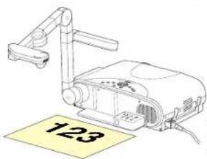
Part names (of the document imaging camera model)

CAUTION
When using the camera, be careful not to pinch your hand or fingers into the arm.
On the document imaging camera model, you can project pictures using the document imaging camera. The document imaging camera can directly project any materials (documents, illustrations, etc.) without using an OHP film.
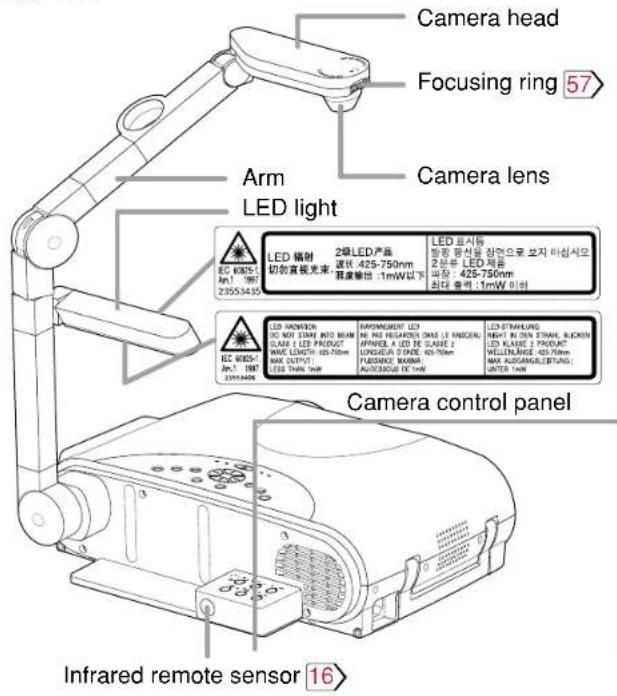
Preparation of the document imaging camera

Before preparations(stowed away) | 1) Raise up the arm.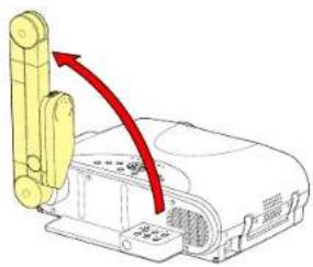 | 2) Extend the arm. 3) Turn the arm.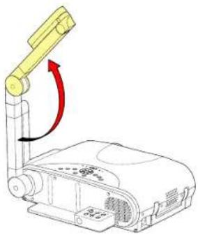 | arm.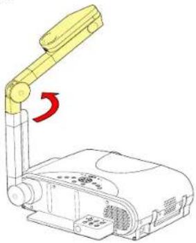 |
4) Open the camera head. 5) Turn the camera head. 6) Pull up the light. 7) Turn the light.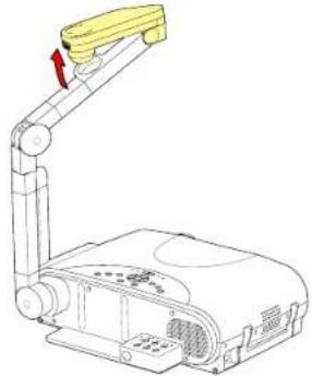 | 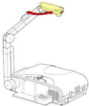 | 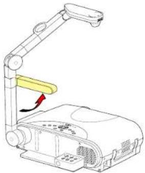 | 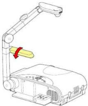 |
Notes
- Never give shocks or impacts to the camera or arm as this may cause malfunction.
- While raising up or turning the arm, the arm moves describing an arc, be careful not to hit your face or your body.
- The figures above are procedures of putting materials on the projector. When the stability of materials is required or the light of the indicator is visible through the materials, place the materials at the back of the projector and set the arm and camera head over them.
Picture projection with the document imaging camera

CAUTION
Do not look into the arm light while it is lit.
Camera control panel
Preparation
1 Project a picture on the screen as explained in the step "Projection on the screen". 28
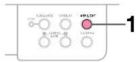
1
ARM LIGHT

Press ARM LIGHT.
The light turns on.
2
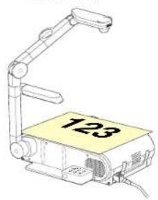
Set a document to be projected.
Place the document (illustrations, etc.) onto or around the projector, and turn the camera head to the direction of the document.
natural_image
Illustration of a projector with a yellow label '123' on its side, no other text or symbols present.Images on the screen
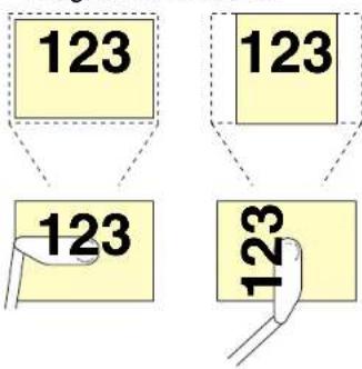
Setting direction
natural_image
Illustration of a projector with a handle and paper label showing number 123 (no text or symbols on the device itself)You can also place the materials at the back of the projector and move the arm and the camera head over them.
Notes
- Use the arm light when necessary according to the brightness of the room.
- When setting the materials on the projector, be careful not press the operation buttons.
Continued
Picture projection with the document imaging camera (continued)
CONTENTS
57
Remote control
Control panel
(Main unit side)
3
Camera control panel
3
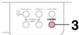
CAMERA

INPUT

INPUT

Press CAMERA to select the camera input mode.
- Pressing CAMERA again will return the input selection to the previous mode.
- You can also select it by pressing INPUT on the remote control or on the main unit. Set the input source on the menu screen when selecting by the INPUT button. 30
- The CAMERA button can be used regardless of the input setting.
- "Camera" is displayed when the picture switches to the document imaging camera's picture.
4
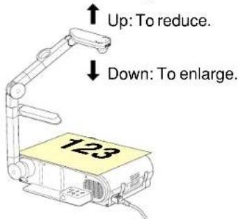
Move the camera head to adjust the size of the picture.
5
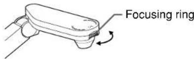
Focus on the picture by turning the focusing ring on the camera head.
Continued
Picture projection with the document imaging camera (continued)

Camera control panel
6
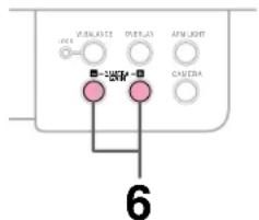
- CAMERA - + GAIN


Press CAMERA GAIN (+/-) to improve view of a camera subject which is too dark or vivid.
Notes
- You can adjust the "Sharpness" of the camera image on the menu screen. 46
- If the image flickers due to a fluorescent light in the room, either turn off the fluorescent light or set the "Shutter" on the menu screen. 46
Note that the image may still flicker due to the lighting, the document status, the image adjustment, etc., even if the "Shutter" setting is changed.
7
When finished, turn off the light and close it, and put back the arm.
Follow the steps of "Preparation of the document imaging camera" in reverse.
Notes
- Though this projector uses a 1.45 million pixel camera unit, the images projected on the screen are 1024 x 768 dot images. If the "Screen size" in the menu screen 46 is set to "Full", the camera's full image is compressed to 1024 x 768 dots. If "Thru" is selected, the 1024 x 768 dots at the center of the image are projected.
- The light turns off automatically when the arm is inclined.
- When the arm is not raised up, the camera source cannot be projected.
- In the camera input selected, the sound is not emitted.
Overlaying projection
CONTENTS
59
You can draw figures or write with a pen on the picture of RGB input or video input, by using the overlay function.
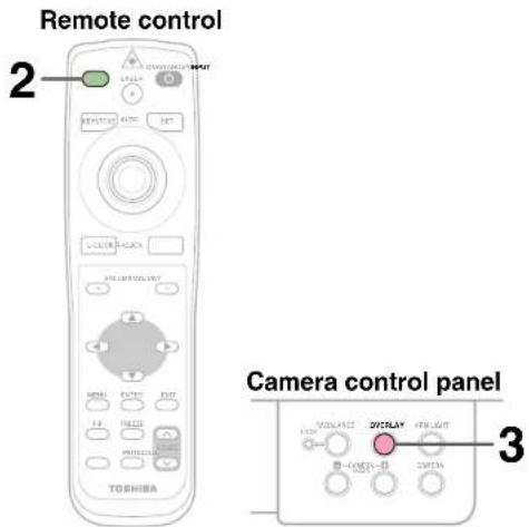
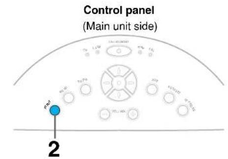
Preparation
1 Project a picture on the screen as explained in the step "Picture projection with the document imaging camera". 56
② Prepare white paper and a red or blue pen.
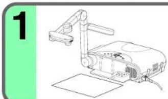
natural_image
Illustration of a projector with a green label '1' on the left (no text or symbols on the diagram itself)Set the white paper on a flat surface and set the camera so that the paper is projected onto the screen.
Adjust the camera to make the white paper be projected on the wholescreen.
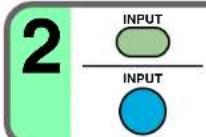
Select the input source using the overlay function by pressing INPUT.
Select an input source other than the camera input.

Press OVERLAY.
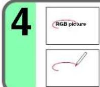
Screen Draw any line on the paper with a red or blue pen.
A drawn line is projected on the screen, overlapped with the picture of the input source.
Paper The position of a pen point can be confirmed on the screen before drawing anything.

Adjust the gain with CAMERA GAIN (+/-) so that the overlaying picture is displayed clearly.
Notes
- Handwriting in colors other than blue or red cannot be displayed properly.
- Handwriting in fine lines may not be displayed properly.
Locking the white balance

Camera control panel
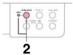
This projector's camera is always being adjusted automatically for projected color balance; however, the balance can shift away from optimum due to the color scheme of the document. Should this occur, the white balance can be set to a fixed condition by using the following procedure.
1
Project a white paper and enlarge it to fill the screen.
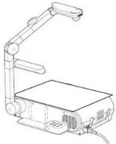
natural_image
Line drawing of a mechanical device with articulated arm and base plate (no text or symbols)2


Press W.BALANCE to turn the LOCK indicator on.
The white balance is locked.
To release the white balance, press W.BALANCE again to turn the LOCK indicator off.
Notes
- If you raise up the arm while the camera input is being selected, the color of the picture may vary for an instant due to the automatic white balance adjustment. This is not a malfunction.
- If you put the arm back and raise it again while the white balance is locked (the LOCK indicator is lit), the projector will release the white balance.
- Depending on the tint of the indoor illumination, the white balance might not be compensated optimally. Should this be the case, or if you would like to adjust it to a desired tint, adjust "R-level", "G-level" or "B-level" on the FULL MENU [Color] screen.
Correcting illuminated defects

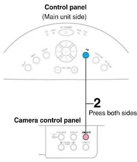
For the CCD image sensor used in the camera unit, in rare cases some of the pixels may be disturbed due to the influence of cosmic rays, etc. This disturbance may cause white spots to appear on the picture.
If white spots appear on the document camera image, use the procedure described below to correct the problem.
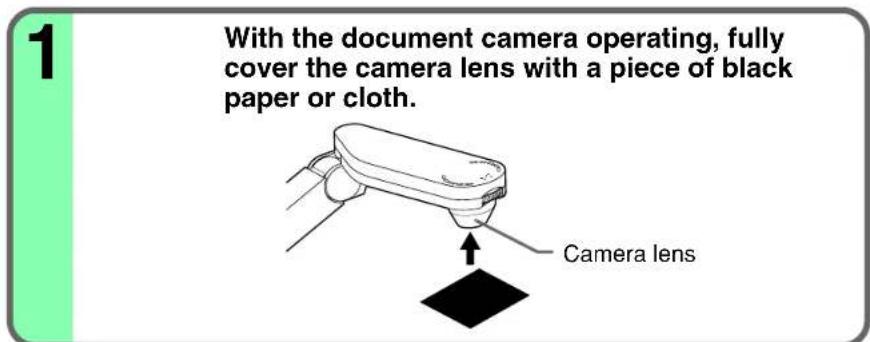
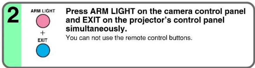
Note
Do not press ARM LIGHT and EXIT buttons simultaneously if the camera lens is not covered. Doing so will not only erase the white spot correction data already set but also result in parts of the image that are properly displayed being corrected. Also be careful if the camera input mode is not selected.
Trouble indications
CONTENTS
62
If there is some problem inside the projector, the indicators light up or blink.
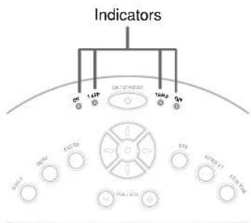
Control panel
(Main unit side)
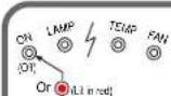 | The power does not come on.→Malfunction of the unit.·Unplug the power cord and call the dealer. |
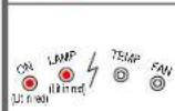 | The lamp turns off or does not light up.→The projector will return to the standby mode in about 2 minutes.If the projector does not operate normally when the power is switched on again, the lamp is at the end of its life duration or the unit has a fault.Lamp's life duration is over, replace the lamp with a new one.66·Unplug the power cord and call the dealer. |
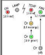 | The power turns off or does not come on.→The inside is too hot, or the projector has been working in an area of high temperature.·Place the projector correctly so the intake and exhaust fan's holes are not covered.Turn the projector off, and leave it for a while, and turn it on again.Clean the air filter.63^Theicon appears before the power turned off.^The projector returns to the standby mode after the fault display has been shown for about 2 minutes. |
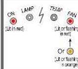 | The power turns off or does not come on.→Trouble with the cooling fan.·Unplug the power cord and call the dealer.^Theicon appears before the power turned off.^The projector returns to the standby mode after the fault display has been shown for about 2 minutes. |
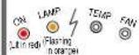 | The power turns off or does not come on.→The lamp cover is not properly attached.·Unplug the power cord and reattach the lamp cover.67^Theicon appears before the power turned off.^The projector returns to the standby mode after the fault display has been shown for about 2 minutes. |
Notes
- If abnormality occurs while operating, unplug the power cord.
- When reinserting the power cord before the lamp has cooled, please wait until the lamp has cooled sufficiently before use. When the lamp is at a high temperature, it may not light and the life duration will be shortened.
Air filter cleaning
CONTENTS
CAUTION
If you use the projector mounted on the ceiling, ask the dealer to carry out the maintenance such as cleaning.
The filter inside the air filter cover is the part to shut out dusts or dregs.
Do not use the projector with the filter taken off.
We recommend you clean the air filter frequently. (The cleaning period is once per 50 hours approximately).
1 Unplug the power cord.
2
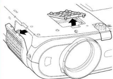
natural_image
Technical line drawing of a mechanical component with mounting holes and a highlighted section (no text or symbols)Take off the air filter cover.
The filter is on the right and bottom side of the projector. The illustration is viewed from the bottom side.
3 Disassemble the air filter. Air filter for the right side
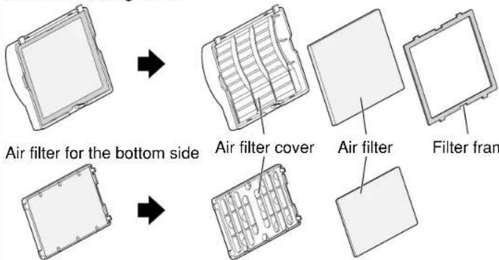
Air filter cleaning (continued)
CONTENTS
Notes
- When the air filter is dusty, the ventilation is impaired. This causes the temperature inside the projector to rise, and may damage the unit.
- Attach the air filter cover firmly after the cleaning. If it is not set correctly, the dusts will enter and they will be projected and overlapped on the picture.
- If you wash the air filter with water, be sure to let it dry fully before reinstalling it. Using it damp will result in malfunction.
- If the air filter is damaged, contact your store of purchase and replace it with a new one. Using a damaged air filter will cause dust or dirt to get inside the projector and onto the images.
4
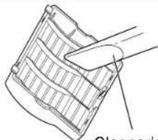
natural_image
Line drawing of a folded paper or plastic sheet with a hand pointing to it (no text or symbols)Clean the air filter.
Use a vacuum cleaner to carefully remove any dust and dirt from the air filter cover, air filter and filter frame.
Be careful that the air filter is not sucked into the vacuum cleaner.
Cleaner's nozzle
5
Assemble the air filter.
Air filter for the right side Air filter for the bottom side
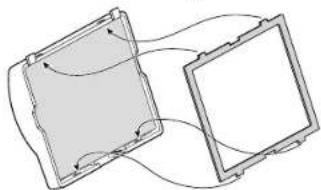
natural_image
Diagram of two rectangular panels with curved arrows indicating flow or interaction (no text or symbols)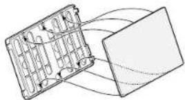
6
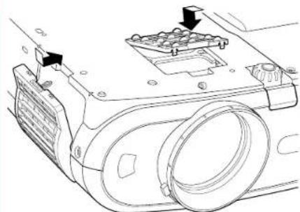
natural_image
Technical line drawing of a mechanical device with mounting holes and a cylindrical component (no text or symbols)Mount the air filter.
Surely mount the air filters on the right and bottom side.
Lens and main unit cleaning
CONTENTS
CAUTION
If you use the projector mounted on the ceiling, ask the dealer to carry out the maintenance such as cleaning.
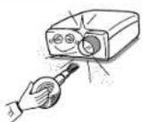
Cleaning the lens
Use a blower or a lens cleaner to clean the lens. Never rub or tap the lens with a hard object as the lens surface is fragile.
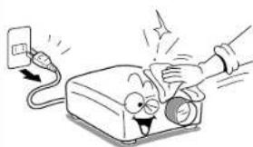
natural_image
Cartoon illustration of a blood pressure monitor with a hand inserting a plug into it (no text or symbols)Cleaning the main unit
• Pull out the power cord before cleaning.
- Use a soft cloth to wipe off stains from the surface.
• To remove difficult stains, use a soft cloth slightly moistened with a weak solution of synthetic detergent and water, and finish with a soft, dry cloth.
Replacing the intake, exhaust fans and air filter
To maintain the efficiency of the projector, replace the intake and exhaust fans about every two to three years.
Ask the dealer for the replacement.
Lamp replacement
CONTENTS
A lamp is consumable supplies. If used for extended periods, images will appear dark, and the lamp could burn out. This is characteristic of a lamp, and is not malfunction. (The lifetime of the lamp depends on conditions of use.) If this happens, replace it with a new one.
CAUTION
- If you use the projector mounted on the ceiling, ask the dealer to carry out the maintenance such as cleaning or replacement of the lamp.
- When replacing, always use lamp "TLPL79" (sold separately). For details, refer to the lamp instruction.
- If you have been using the projector, the lamp will be very hot, and may cause burn injuries. Wait for the lamp to cool (for longer than 1 hour) before replacing it.
- If the lamp should break, please handle with care to avoid injury due to broken pieces and contact your dealer for repair service.
1 Unplug the power cord.
2 Wait until the lamp gets cool enough.
Take off the bottom panel
Loosen the two s cover.
Lamp cover
4
①
②
Lamp cover
4
①
②
Pull out the lamp.
Take off the lamp cover on the bottom panel.
Loosen the two screws, and pull off the lamp cover.
Loosen the two fixing screws, and lift up the handle to pull out the lamp.
Lamp replacement (continued)

Notes
- When the CALL button is pressed, the "Lamp time" (the approximate amount of time the lamp has been used) will be displayed. 41
- The lamp should be replaced if the total working time exceeds about 1,500 hours.
When the "Lamp time" is displayed as 1,500 hours, the icon 📋 appear. They will disappear when you do some operation.
- Attach the lamp cover firmly after replacing the lamp. If it is not set correctly, the power will not turn on.
- Use a new lamp when replacing it.
- The lamp is made of glass and is very fragile. Do not touch the lamp with your bare hands and do not jolt or damage it. Do not try to use an exhausted lamp.
- Dispose of the exhausted lamp as toxic waste.
5 Load a new lamp.
Slide until it hits the bottom and tighten the two fixing screws.
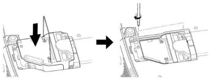
natural_image
Technical line drawing showing a mechanical assembly before and after disassembly, with no visible text or symbols.6
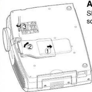
Attach the lamp cover.
Slide the cover into place and tighten the two screws.
7 Reset the lamp timer.
Refer to the lamp instructions for resetting.
Before calling service personal

Check the following points before asking for support service. Refer also to "Trouble indications". 62
| Symptom | Cause | Correction | Page |
| The power does not come on. | · The power cord is disconnected. | Firmly plug in the power cord. | 19 |
| · The lamp cover is not attached correctly. | Attach the cover correctly. | 67 | |
| The power turns off while using the projector. | · The ambient temperature of the projection room is too high. | Lower the ambient temperature of the projection room, and turn the power on. | 62 |
| No image appears. | · The lens cover is on. | Take off the lens cover. | 19 |
| · The wrong input is selected. | Select the input source correctly. | 30 | |
| · The muting mode is on. | Press MUTE to restore the picture. | 37 | |
| · The “Brightness” adjustment is at its darkest. | Make the “Brightness” adjustment. | 45 | |
| · The source is not correctly connected to the projector. | Connect the source correctly to the projector. | 22 - 25 | |
| No sound is heard. | · The wrong input is selected. | Select the input source correctly. | 30 |
| · The muting mode is on. | Press MUTE to restore the sound. | 37 | |
| · The sound volume is at it’s minimum. | Adjust the sound volume. | 32 | |
| · The source is not correctly connected to the projector. | Connect the source correctly to the projector. | 22 - 25 | |
| Desired input source cannot be selected by the INPUT button. | · Input is not set so that it can be selected with the INPUT button. By default, only the Analog RGB(1) and Video input modes can be selected. | Set from the menu screen so that the source can be selected with the INPUT button. | 4530 |
| Analog RGB(1) input or Y/PB/PR input colors are not right. | · The COMPUTER IN 1 connector's input setting is wrong. | On the menu screen, set for the proper input signal type. | 45 |
| Analog RGB(2) input image does not appear. | · The COMPUTER IN 2 connector's input setting is wrong. | On the menu screen, set for the proper input signal type. | 45 |
| · The signal cable type is wrong. | Use a proper signal cable. | 23 | |
| Digital RGB input image does not appear. | · The COMPUTER IN 2 connector's input setting is wrong. | At the menu screen, set for the proper input signal type. | 45 |
| · The signal cable type is wrong. | Use a proper signal cable. | 23 | |
| The image is blurred. Focusing is uneven. | · The lens is dirty. | Clean the lens with a blower or lens cleaner, etc. | 65 |
| · The picture is out of focus. | Focus the picture. | 31 | |
| · The projection distance is not appropriate. | Adjust the distance properly. | 18 | |
| · The projecting light is not hitting the screen squarely. | Adjust the projecting direction so that the light hits the screen squarely. | 18 | |
| · The “Brightness”, “Contrast”, “Sharpness” or “Phase” adjustments are not correct. | Make the “Picture” adjustments. | 45 | |
| The picture is dim. | · The “Brightness” or “Contrast” adjustments are not correct. | Make the “Picture” adjustments. | 45 |
| · The lamp life is ending. | Replace the lamp. | 66 |
Before calling service personal (continued)

| Symptom | Cause | Correction | Page |
| The color is faint.The tint is not good. | · The “Color”, “Tint”, “R-Level”, “G-Level” or “B-Level” adjustments are not correct. | Make the “Picture” adjustments. | 48 |
| · The lamp life is ending. | Replace the lamp. | 66 | |
| The remote control does not work. | · The remote control is not facing the remote sensor. | Face the remote control transmitter toward the remote sensor on the projector. | 16 |
| · The remote control is too far away. | Operate within about 5 meters. | 16 | |
| · There is an obstruction between the remote control and the remote sensor. | Remove the obstacle. | - | |
| · The batteries are exhausted. | Replace the batteries. | 15 | |
| Mouse function cannot be used from the remote control unit. | · The USB cable is not properly connected. | Connect the USB cable properly. | 42 |
| · The computer or OS is not compatible. | The remote control mouse function is not available. | - | |
| · The batteries are exhaust. | Replace the batteries. | 15 | |
| Document camera image is blurry. | · The lens is dirty. | Clean the lens with a blower or lens cleaner, etc. | 65 |
| · The picture is out of focus. | Focus the picture by turning the focus ring. | 57 | |
| · The light is not on. | Turn on the light. | 56 | |
| Document camera image flickers. | · Image is being affected by fluorescent light in the room. | Set the shutter speed on the menu screen. | 45 |
| Document camera image movement is awkward. | · The image’s number of frames is low. This is not a malfunction. | ||
| Horizontal stripes appear when document projected with the document camera is moved. | · The image’s number of frames is low. This is not a malfunction. |
Pin assignment of COMPUTER IN connector
CONTENTS
70
COMPUTER IN 1
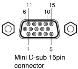
Input signal
Analog R, G, B signal: 0.7V(p-p) 75Ω
Horizontal sync signal:
TTL level (positive/negative polarity)
Vertical sync signal:
TTL level (positive/negative polarity)
Y signal: 1.0V(p-p) 75Ω
P_B , P_R signal: 0.7V(p-p) 75Ω
COMPUTER IN 2
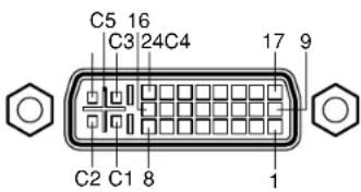
DVI ANALOG & DIGITAL connector
Analog input signal
Analog R, G, B signal: 0.7V(p-p) 75Ω
Horizontal sync signal:
TTL level (positive/negative polarity)
Vertical sync signal:
TTL level (positive/negative polarity)
| Pin No. | Description | |
| RGB input | Y/PB/PR input | |
| 1 | Video signal (Red) | Color difference signal (PR) |
| 2 | Video signal (Green) | Luminance signal (Y) |
| 3 | Video signal (Blue) | Color difference signal (PD) |
| 4 | GND | * |
| 5 | GND | * |
| 6 | GND (Red) | GND (PR) |
| 7 | GND (Green) | GND (Y) |
| 8 | GND (Blue) | GND (PB) |
| 9 | N.C | * |
| 10 | GND | * |
| 11 | GND | * |
| 12 | DDC data | * |
| 13 | Horizontal sync signal | * |
| 14 | Vertical sync signal | * |
| 15 | DDC clock | * |
*: Do not connect anything.
| Pin No. | Description |
| 1 | T.M.D.S. data 2- |
| 2 | T.M.D.S. data 2 + |
| 3 | T.M.D.S. data 2/4 shield |
| 4 | T.M.D.S. data 4 - |
| 5 | T.M.D.S. data 4 + |
| 6 | DDC clock |
| 7 | DDC data |
| 8 | Analog vertical sync signal |
| 9 | T.M.D.S. data 1 - |
| 10 | T.M.D.S. data 1 + |
| 11 | T.M.D.S. data 1/3 shield |
| 12 | T.M.D.S. data 3 - |
| 13 | T.M.D.S. data 3 + |
| 14 | +5V power |
| 15 | GND (+5V, H Sync & V Sync) |
| Pin No. | Description |
| 16 | Hot plug detection |
| 17 | T.M.D.S. data 0 - |
| 18 | T.M.D.S. data 0 + |
| 19 | T.M.D.S. data 0/5 shield |
| 20 | T.M.D.S. data 5 - |
| 21 | T.M.D.S. data 5 + |
| 22 | T.M.D.S. clock shield |
| 23 | T.M.D.S. clock + |
| 24 | T.M.D.S. clock - |
| C1 | Analog Video signal (Red) |
| C2 | Analog Video signal (Green) |
| C3 | Analog Video signal (Blue) |
| C4 | Analog horizontal sync signal |
| C5 | Analog GND (R,G & B) |
Applicable signal
CONTENTS
71
Applicable computer signal
The unit is applicable to the following signals. However, some computers may have different timings than those in the chart. Make the necessary adjustments if the picture has flickers or is blurred.
Signal Timing (Horizontal)
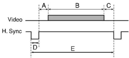
Signal Timing (Vertical)
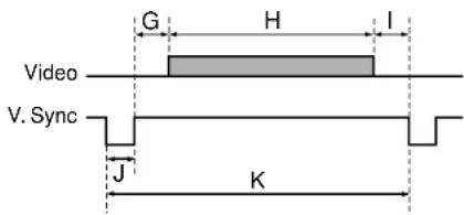
Timing chart
| Mode | Resolution | A(Pixels) | B(Pixels) | C(Pixels) | D(Pixels) | E(Pixels) | fh(kHz) | fv(Hz) | Clock(MHz) | G(Lines) | H(Lines) | I(Lines) | J(Lines) | K(Lines) |
| TEXT70 640 x 350 50 640 | 14 96 800 31.4 | 69 70.086 | 25.175 | 59 350 38 | 2 449 | |||||||||
| TEXT70 640 x 400 50 640 | 14 96 800 31.4 | 69 70.086 | 25.175 | 34 400 13 | 2 449 | |||||||||
| TEXT85 640 x 350 96 640 | 32 64 832 37.8 | 61 85.080 | 31.500 | 60 350 32 | 3 445 | |||||||||
| TEXT85 640 x 400 96 640 | 32 64 832 37.8 | 61 85.080 | 31.500 | 41 400 1 | 3 445 | |||||||||
| NEC PC98 24k 640 x 400 | 85 640 59 64 8 | 48 24.820 | 55.900 | 21.047 25 | 400 11 8 | 444 | ||||||||
| VGA60 640 x 480 48 640 | 16 96 800 31.46 | 9 59.940 | 25.175 3 | 3 480 10 | 2 525 | |||||||||
| VGA72 640 x 480 128 640 | 24 40 832 37.8 | 61 72.809 | 31.500 | 28 480 9 | 3 520 | |||||||||
| VGA75 640 x 480 120 640 | 16 64 840 37.5 | 500 75.000 | 31.500 | 16 480 1 | 3 500 | |||||||||
| VGA85 640 x 480 80 640 | 56 56 832 43.26 | 9 85.008 | 36.000 2 | 5 480 1 3 | 509 | |||||||||
| MAC13" 640 x 480 96 640 | 64 64 864 35.0 | 00 66.667 | 30.240 | 39 480 3 | 3 525 | |||||||||
| SVGA56 | 800 x 600 | 128 | 800 | 24 | 72 | 1024 | 35.156 | 56.250 | 36.000 | 22 | 600 | 1 | 2 | 625 |
| SVGA60 | 800 x 600 | 88 | 800 | 40 | 128 | 1056 | 37.879 | 60.317 | 40.000 | 23 | 600 | 1 | 4 | 628 |
| SVGA72 | 800 x 600 | 64 | 800 | 56 | 120 | 1040 | 48.077 | 72.188 | 50.000 | 23 | 600 | 37 | 6 | 666 |
| SVGA75 | 800 x 600 | 160 | 800 | 16 | 80 | 1056 | 46.875 | 75.000 | 49.500 | 21 | 600 | 1 | 3 | 625 |
| SVGA85 | 800 x 600 | 152 | 800 | 32 | 64 | 1048 | 53.674 | 85.061 | 56.250 | 27 | 600 | 1 | 3 | 631 |
| MAC16" | 832 x 624 | 216 | 832 | 40 | 64 | 1152 | 49.725 | 74.550 | 57.283 | 39 | 632 | 1 | 3 | 667 |
| XGA43i | 1024 x 768 | 56 | 1024 | 8 | 176 | 1264 | 35.522 | 43.479 | 44.900 | 20 | 768 | 0 | 4 | 817 |
| XGA60 | 1024 x 768 | 160 | 1024 | 24 | 136 | 1344 | 48.363 | 60.004 | 65.000 | 29 | 768 | 3 | 6 | 806 |
| XGA70 | 1024 x 768 | 144 | 1024 | 24 | 136 | 1328 | 56.476 | 70.069 | 75.000 | 29 | 768 | 3 | 6 | 806 |
| XGA75 | 1024 x 768 | 176 | 1024 | 16 | 96 | 1312 | 60.023 | 75.029 | 78.750 | 28 | 768 | 1 | 3 | 800 |
| XGA85 | 1024 x 768 | 208 | 1024 | 48 | 96 | 1376 | 68.677 | 84.997 | 94.500 | 36 | 768 | 1 | 3 | 808 |
| MAC19" | 1024 x 768 | 180 | 1024 | 20 | 96 | 1320 | 60.197 | 74.872 | 73.200 | 30 | 768 | 3 | 3 | 804 |
Applicable signal (continued)
CONTENTS
72
Timing chart (Continued)
| Mode Resolution | A(Pixels) | B(Pixels) | C(Pixels) | D(Pixels) | E(Pixels) | fh(kHz) | fv(Hz) | Clock(MHz) | G(Lines) | H(Lines) | I(Lines) | J(Lines) | K(Lines) | |
| *SXGA1152x864 75Hz 1 | 152 x 864 256 11 | 52 64 128 | 1600 67 | 7.500 75.000 | 108.000 | 32 86 | 1 3 900 | |||||||
| *SXGA1280x960 60Hz 1 | 280 x 960 312 12 | 80 96 112 | 1800 60 | 0.000 60.000 | 108.000 | 36 96 | 1 3 1000 | |||||||
| *SXGA1280x960 85Hz 1 | 280 x 960 224 12 | 80 64 160 | 1728 85 | 9.938 85.002 | 148.500 | 47 96 | 1 3 101 | |||||||
| *SXGA1280x1024 60Hz | 1280 x 1024 248 | 1280 48 | 112 1688 | 63.981 60 | 0.020 108 | 000 38 | 1024 1 3 | 1066 | ||||||
| *SXGA1280x1024 75Hz | 1280 x 1024 248 | 1280 16 | 144 1688 | 79.976 75 | 0.025 135 | 000 38 | 1024 1 3 | 1066 | ||||||
| *SXGA1280x1024 85Hz | 1280 x 1024 224 | 1280 64 | 160 1728 | 91.146 85 | 0.024 157 | 500 44 | 1024 1 3 | 1072 | ||||||
| *UXGA60 1600 x 1200 3 | 04 1600 64 192 2 | 160 75.00 | 00 60.000 | 162.000 | 46 1200 | 1 3 1250 | ||||||||
| *UXGA65 1600 x 1200 3 | 04 1600 64 192 2 | 160 81.25 | 00 65.000 | 175.500 | 46 1200 | 1 3 1250 | ||||||||
| *UXGA70 1600 x 1200 3 | 04 1600 64 192 2 | 160 87.50 | 00 70.000 | 189.000 | 46 1200 | 1 3 1250 | ||||||||
| *UXGA75 1600 x 1200 3 | 04 1600 64 192 2 | 160 93.75 | 00 75.000 | 202.500 | 46 1200 | 1 3 1250 |
Notes
- Signal sources marked “*” are displayed in compressed format, so some of their data may be missing or their picture quality may be degraded.
- With analog RGB inputs, if the signal source's dot clock frequency exceeds 165 MHz, not all of the pixel signals can be sampled.
- For digital RGB inputs, the projector is not compatible with signal sources whose dot clock frequency exceeds 162 MHz.
The compatible Video and S-Video signal
| Mode | fh (kHz) | fv (Hz) | fsc (MHz) |
| NTSC | 15.73 | 60 | 3.58 |
| PAL | 15.63 | 50 | 4.43 |
| SECAM | 15.63 | 50 | 4.25 or 4.41 |
| PAL-M | 15.73 | 60 | 3.58 |
| PAL-N | 15.63 | 50 | 3.58 |
| PAL-60 | 15.73 | 60 | 4.43 |
| NTSC4.43 | 15.73 | 60 | 4.43 |
The compatible components video signal (Y/PB/PR)
| Mode | fh (kHz) | fv (Hz) |
| 525i | 15.73 | 59.94 |
| 525p | 31.47 | 59.94 |
| 625i | 15.63 | 50.00 |
| 750p | 45.00 | 60.00 |
| 1125i | 33.75 | 60.00 |
Controlling the projector by using RS-232C
CONTENTS
73
You can also control the projector by entering the command from a computer via RS-232C.
Signal assignment of RS-232C
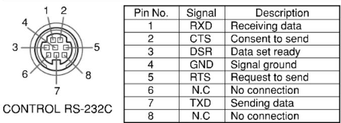
Interface format
| 1 | Communication method | RS-232C9600 bps, No parity, Data length: 8 bits,Stop bit: 1 bit | ||
| 2 | Communication format | STX (02h) | Command (3Byte) | ETX (03h) |
| One command only can be used per communication. | ||||
| 3 | Data format | Commands shall be composed of alphanumeric characters of ASCII description.Use only capital letters. | ||
| 4 | Return value | Acknowledge | ACK (06h) | |
| Not Acknowledge | NAK (15h) | |||
Command list
| Classification | Items/Status | Selection Adjustment Command | Command | Analog RGB(1) Analog RGB(2) | Digital RGB | Video S-Video | Y/PB/PR | Camera | |
| Power On P | ON - Yes Yes Yes Yes Yes | ||||||||
| Off (with confirmation message) POF - | Yes Yes Yes | Yes Yes | |||||||
| Shut Down (without confirmation message) | PSD - Yes | Yes Yes Yes Yes | |||||||
| Normal (RS-232C Condition Display Off) DOF | - Yes Yes Yes Yes Yes Yes | ||||||||
| Picture | Contrast | VCN | Yes | Yes | Yes | Yes | Yes | Yes | |
| Brightness | VBR | Yes | Yes Yes | Yes Yes Yes | |||||
| Sharpness | VSH | Yes | - | - | Yes | Yes | Yes | ||
| Camera gain | Increase | CGU | - | - | - | - | - | Yes | |
| Decrease | CGD | - | - | - | - | - | Yes | ||
| Picture mode | Bright | MVB | - | Yes | Yes | - | - | - | |
| True color | MVP | - | Yes | Yes | - | - | - | ||
Notes
- When commands are transmitted serially, wait for the reply of the projector (acknowledge or not acknowledge) before sending the next command.
- Adjustment commands include "ARG" (increase adjustment value) and "ALF" (decrease adjustment value). For usable items (marked "Yes"), send after the selection command.
- The "Yes" marks in the input source columns indicate that that command can be used.
Continued

Controlling the projector by using RS-232C (continued)

74
| Classification | Items/Status | Selection A Adjustment Command | Command | Analog RGB(1) Analog RGB(2) | Digital RGB | Video S-Video | Y/PB/PR | Camera | |
| Picture Video (Continued) | o mode Auto. KV0 --- Yes --- | ||||||||
| NTSC KV1 --- Yes --- | |||||||||
| PAL KV2 --- Yes --- | |||||||||
| SECAM KV3 --- Yes --- | |||||||||
| PAL-N KV4 --- Yes --- | |||||||||
| PAL-M | KV5 --- Yes --- | ||||||||
| PAL60 | KV6 --- Yes --- | ||||||||
| NTSC4.43 | KV7 --- Yes --- | ||||||||
| Signal format | Auto. | SG0 | - | - | - | - | Yes | - | |
| 525i | SG1 | - | - | - | - | Yes | - | ||
| 525p SG2 | ---- | Yes | - | ||||||
| 625i | SG3 | - | - | - | - | Yes | - | ||
| 750p SG4 | ---- | Yes | - | ||||||
| 1125i | SG5 | - | - | - | - | Yes | - | ||
| Shutter | Auto. | CSA | - | - | - | - | - | Yes | |
| 50Hz | CS0 | - | - | - | - | - | Yes | ||
| 60Hz | CS1 | - | - | - | - | - | Yes | ||
| Screen size | Full | MSF | - | Yes | Yes | Yes | Yes | Yes | |
| Thru | MST | - | Yes | Yes | Yes | Yes | Yes | ||
| Wide | MSW | - | - | - | Yes | Yes | - | ||
| Picture reset | DRV | - | Yes | Yes | Yes | Yes | Yes | ||
| Position | H-position | PHP | Yes | Yes | - | - | - | - | |
| V-position | PVP | Yes | Yes | - | - | - | - | ||
| Phase | PPH | Yes | Yes | - | - | - | - | ||
| Frequency | PCK | Yes | Yes | - | - | - | - | ||
| Position reset | DRP | - | Yes | - | - | - | - | ||
Controlling the projector by using RS-232C (continued)

| Classification | Items/Status | Selection Adjustment Command | Command | Analog RGB(1) Analog RGB(2) | Digital RGB | Video S-Video | Y/PB/PR | Camera | |
| Color Color | VCL Yes - - Yes Yes - | ||||||||
| Tint VTN Yes - - Yes - - | * | ||||||||
| R-level VLR Yes Yes Yes Yes Yes Yes | |||||||||
| G-level | VLG Yes | Yes Yes Yes | Yes Yes | ||||||
| B-level | VLB | Yes Yes | Yes Yes Yes | Yes | |||||
| Color reset | DRC | - Yes Yes | Yes Yes Yes | ||||||
| Audio | Volume | Increase | VLU | - | Yes | Yes | Yes | Yes | - |
| Decrease VLD | - Yes Yes Yes Yes - | ||||||||
| Speaker output | On | AS1 | - | Yes | Yes | Yes | Yes | - | |
| Off | AS0 | - Yes Yes Yes Yes - | |||||||
| Channel select (RCA) | L+R | APA | - | - | - | Yes | - | - | |
| L | APL | - | -- Yes | -- | |||||
| R | APR | - | -- Yes | -- | |||||
| Loudness (RCA) | Off | LR0 | - | - | - | Yes | - | - | |
| On | LR1 | - | - | - | Yes | - | - | ||
| Channel select (Mini) | L+R | AMA | - | Yes | Yes | - | Yes | - | |
| L | AML | - | Yes | Yes | - | Yes | - | ||
| R | AMR | - | Yes | Yes | - | Yes | - | ||
| Loudness (Mini) | Off | LM0 | - | Yes | Yes | - | Yes | - | |
| On | LM1 | - Yes | Yes - | Yes - | |||||
| Audio reset | DRA | - Yes Yes Yes Yes - | |||||||
| Display | V-keystone | PKV | Yes | Yes | Yes | Yes | Yes | Yes | |
| H-keystone | PKH | Yes Yes | Yes Yes Yes | Yes | |||||
| Keystone reset | DRK | - Yes Yes Yes Yes Yes | |||||||
| Language | English | LEN | - | Yes | Yes | Yes | Yes | Yes | |
| French | LFR | - Yes Yes Yes Yes Yes | |||||||
| German | LGR | - Yes Yes Yes Yes Yes | |||||||
| Italian | LIT | - Yes Yes Yes Yes Yes | |||||||
| Spanish | LSP | - | Yes Yes | Yes Yes Yes | |||||
| Portuguese | LPO | - | Yes | Yes | Yes | Yes | Yes | ||
| Japanese | LJP - Yes | Yes Yes Yes Yes | |||||||
| Chinese(Simplified) | LPK | - Yes Yes Yes Yes Yes | |||||||
| Chinese(Traditional) | LKT | - Yes Yes Yes Yes Yes | |||||||
| Korean LKK | - Yes | Yes Yes Yes Yes | |||||||
* Not possible for PAL/SECAM.
Continued

Controlling the projector by using RS-232C (continued)

| Classification | Items/Status | Selection Adjustment Command | Command | Analog RGB(1) Analog RGB(2) | Digital RGB | Video S-Video | Y/PB/PR | Camera | ||
| Display Icon (Continued) | On MO0 - Yes Yes Yes | Yes Yes | ||||||||
| Off MO1 - Yes | Yes Yes Yes | Yes | ||||||||
| Menu position Upper left MP1 - Yes Yes | Yes Yes Yes | |||||||||
| Lower left MP2 | - Yes Yes Yes | Yes Yes | ||||||||
| Upper right MP3 | 3 - Yes Yes | Yes Yes Yes | ||||||||
| Lower right MP4 | 4 - Yes Yes | Yes Yes Yes | ||||||||
| Menu translucent On MB1 - Yes Yes Yes Yes Yes Yes | ||||||||||
| Off MB0 - Yes | Yes Yes Yes | Yes | ||||||||
| Display reset (except keystone) | DRD | - | Yes | Yes | Yes | Yes | Yes | |||
| Default setting | Input source setting | COMPUTER IN 1 | On | I10 | - | Yes | Yes | Yes | Yes | Yes |
| Off | I11 | - Yes Yes Yes Yes Yes | ||||||||
| Analog RGB(1) | ISO | - Yes Yes Yes Yes Yes | ||||||||
| Y/PB/PR | IS1 | - | Yes | Yes | Yes | Yes | Yes | |||
| COMPUTER IN 2 | On | I20 | - | Yes | Yes | Yes | Yes | Yes | ||
| Off | I21 | - Yes Yes Yes Yes Yes | ||||||||
| Analog RGB(2) | IV0 | - Yes Yes Yes Yes Yes | ||||||||
| Digital RGB IV1 | - Yes Yes Yes Yes Yes | |||||||||
| VIDEO | On | I30 | - Yes Yes Yes Yes Yes | |||||||
| Off | I31 | - Yes Yes Yes Yes Yes | ||||||||
| S-VIDEO | On | I40 | - Yes Yes Yes Yes Yes | |||||||
| Off | I41 | - Yes Yes Yes Yes Yes | ||||||||
| CAMERA | On | I60 | - Yes Yes Yes Yes Yes | |||||||
| Off | I61 | - Yes Yes Yes Yes Yes | ||||||||
| Projection mode | Standard | PJ0 | - | Yes | Yes | Yes | Yes | Yes | ||
| Rear | PJ1 | - Yes Yes Yes Yes Yes | ||||||||
| Ceiling | PJ2 | - Yes Yes Yes Yes Yes | ||||||||
| Rear ceiling | PJ3 | - Yes Yes Yes Yes Yes | ||||||||
| No signal background | Logo | BG0 | - | Yes | Yes | Yes | Yes | Yes | ||
| Blue background | BG1 | - Yes Yes Yes Yes Yes | ||||||||
| Non | BG2 | - Yes Yes Yes Yes Yes | ||||||||
| No signal power off | Off | PN0 | - | Yes | Yes | Yes | Yes | Yes | ||
| 5 min. | PN1 | - Yes Yes Yes Yes Yes | ||||||||
| Power on | Manual | AP0 | - | Yes | Yes | Yes | Yes | Yes | ||
| Auto. | AP1 | - Yes Yes Yes Yes Yes | ||||||||
Controlling the projector by using RS-232C (continued)

| Classification | Items/Status | Selection Adjustment Command | Command | Analog RGB(1) Analog RGB(2) | Digital RGB | Video S-Video | Y/PB/PR | Camera | |
| Default setting (Continued) | Startup screen On MS0 | - Yes Yes Yes | Yes Yes | ||||||
| Off MS1 - Yes | Yes Yes Yes | Yes | |||||||
| Default setting reset DRI - Yes Yes Yes | Yes Yes | ||||||||
| Reset Reset | all DRS - Yes Yes Yes Yes Yes | ||||||||
| H-reference reset | PKR - Yes Yes Yes Yes Yes | ||||||||
| Status display (CALL) | DON | - Yes Yes Yes Yes Yes | |||||||
| Input selection | Toggle | IN0 | - Yes Yes Yes Yes Yes | ||||||
| COMPUTER-1 | IN1 | - | Yes | Yes | Yes | Yes | Yes | ||
| COMPUTER-2 | IN2 | - Yes Yes Yes Yes Yes | |||||||
| VIDEO | IN3 | - Yes Yes Yes Yes Yes | |||||||
| S-VIDEO | IN4 | - Yes Yes Yes Yes Yes | |||||||
| CAMERA | IN6 | - Yes Yes Yes Yes Yes | |||||||
| RESIZE | Increase the enlargement ratio | RUP - Yes Yes Yes Yes | |||||||
| Decrease the enlargement ratio (Minimum: reset status) | RDW | - Yes Yes Yes Yes Yes | |||||||
| Move the enlargement section | Up | PO1 | - Yes Yes Yes Yes Yes | ||||||
| Down | PO2 | - Yes Yes Yes Yes Yes | |||||||
| Left | PO3 | - Yes Yes Yes Yes Yes | |||||||
| Right | PO4 | - Yes Yes Yes Yes Yes | |||||||
| Enlargement reset | RS0 | - Yes Yes Yes Yes Yes | |||||||
| FREEZE | On | FON - Yes Yes Yes Yes | |||||||
| Off | FOF | - Yes Yes Yes Yes Yes | |||||||
| MUTE | On | MON | - Yes Yes Yes Yes Yes | ||||||
| Off | MOF | - Yes Yes Yes Yes Yes | |||||||
| PIP | On | PIN | - | Yes | Yes | - | - | - | |
| Off | PIF | - | Yes | Yes | - | - | - | ||
| PIP input source | Video | PI0 | - | Yes | Yes | - | - | - | |
| S-Video | PI1 | - | Yes | Yes | - | - | - | ||
| PIP size | Small | PS0 | - | Yes | Yes | - | - | - | |
| Middle | PS1 | - | Yes | Yes | - | - | - | ||
| Large | PS2 | - | Yes | Yes | - | - | - | ||
| PIP position | Upper left | PP0 | - | Yes | Yes | - | - | - | |
| Upper right | PP1 | - | Yes | Yes | - | - | - | ||
| Lower left | PP2 | - | Yes | Yes | - | - | - | ||
| Lower right | PP3 | - | Yes | Yes | - | - | - | ||
Controlling the projector by using RS-232C (continued)

| Classification | Items/Status | Selection Adjustment Command Command | Analog RGB(1) Analog RGB(2) | Digital RGB | Video S-Video | Y/PB/PR | Camera | ||
| PIP PIP audio (Continued) | io source Main PA0 - Yes Yes --- | ||||||||
| Sub PA1 - Yes Yes --- | |||||||||
| PIP reset DRW - Yes Yes --- | |||||||||
| AUTO SET | PAT | - Yes Yes --- | |||||||
| Auto. V-keystone | PKA | - | Yes | Yes | Yes | Yes | Yes | ||
| Overlay | On | CON | - | Yes | Yes | Yes | Yes | - | |
| Off | COF | - | Yes | Yes | Yes | Yes | - | ||
| Camera | Shortcut | CDR | - | Yes | Yes | Yes | Yes | Yes | |
| Auto. W/B | On | CW1 | - | Yes | Yes | Yes | Yes | Yes | |
| Off | CW0 | - | Yes | Yes | Yes | Yes | Yes | ||
| Lighting | On | CL1 | - | Yes | Yes | Yes | Yes | Yes | |
| Off | CL0 | - | Yes | Yes | Yes | Yes | Yes | ||
Specifications
CONTENTS
Main unit
Power consumption 340W (Standby: 20W)
Mass TLP790: 4.2kg
TLP791: 5.0kg
Dimensions TLP790: 338 x 101 x 268 (mm) (W/H/D)
(Includes the protrusion parts) TLP791: 338 x 101 x 323 (mm) (W/H/D)
Cabinet Material PC+ABS resin and ABS resin
Ambient environment Temperature : 0 deg. to 35 deg.
Humidity : 30% to 70% RH
Lamp High pressure mercury lamp
Projection screen size 32 to 300 inches
Projection distance 1.3 to 10.2m
Speaker 1W (monaural)
Connectors
• COMPUTER IN 1 Mini D-sub 15-pin
Analog RGB(1)/Y/PB/PR (combination)
• COMPUTER IN 2 DVI ANALOG & DIGITAL connector
Analog RGB(2)/Digital RGB (combination)
• MONITOR OUT Mini D-sub 15-pin
Analog RGB/Y/PB/PR (combination)
• S-VIDEO IN Mini DIN 4-pin
• VIDEO IN 1V(p-p), 75Ω, RCA pin jack
• AUDIO(L/R) IN 1.3V(rms), more than 22kΩ, RCA pin jack x 2
• AUDIO IN 1.3V(rms), more than 22kΩ,
3-panel transmission
Panel size
1.0 inches
Driving system
TFT active matrix
Picture elements
786,432 pixels (1024 x 768 dots) (H./V.) x 3
Projection lens
Lens
Zooming lens
F=1.7 to 2.1 f=33.6 to 42mm
Focusing
Manual operation
Zooming
Manual operation
Document imaging camera (with camera model)
Lens
F = 3.1, f = 6.4mm
Focusing
Manual operation
Zoom
None (adjusted by distance to subject)
Iris
Auto./Manual
Image element
1/2 inch CCD
Effective pixels for pickup section
1,447,680 pixels (1392 x 1040 dots) (H./V.)
Lighting
LED light (class 2)
Specifications (continued)

Accessories
Owner's manual (Getting started) .1.
Power cord .*Note.DVI.cable.1.(2m).Carry-on bag 1
natural_image
Simple 3D isometric view of a rectangular block with a flat top and bottom edge (no text or symbols)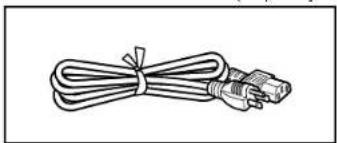
natural_image
Line drawing of a cable with a connector, tied with a strap (no text or symbols)
natural_image
Illustration of two coaxial connectors with coiled cable (no text or symbols)
natural_image
Line drawing of a rectangular device with internal compartments and straps (no text or symbols)
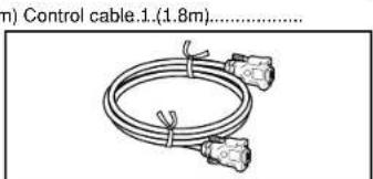
natural_image
Illustration of a coiled cable with two connectors and a tape, no text or symbols present.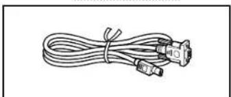
natural_image
Line drawing of a coiled cable with three connectors (no text or symbols)
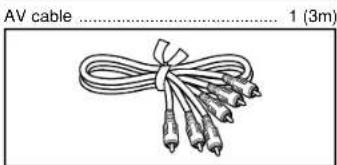
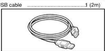
natural_image
Coiled cable with two connectors, labeled 'SB cable' and measurement annotation (2m), no other text or symbols present.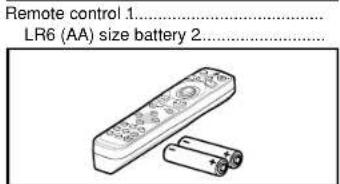
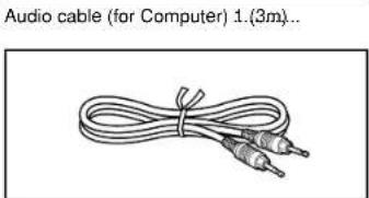
natural_image
Audio cable (for Computer) 1.(3m)... with two connected audio cables (no text or symbols on the cable itself)Sold separately
Replacement lamp TLPL79
- The design and specifications are subject to change without notice.
Note
The shape and number of the power cord varies with the destination.
Trademarks
NEC, PC-98 series are trademarks of NEC Corporation.
VGA, SVGA, XGA, SXGA, UXGA are trademarks or registered trademarks of International Business Machines Corporation.
Macintosh is a registered trademark of Apple Computer, Inc.
Windows is a registered trademark of Microsoft Corporation in the U.S. and other countries.
Display Data Channel is a trademark of Video Electronics Standard Association.
TOSHIBA CORPORATION
- SAFETY PRECAUTIONS
- WARNING: TO REDUCE THE RISK OF FIRE OR ELECTRIC SHOCK, DO NOT EXPOSE THIS APPLIANCE TO RAIN OR MOISTURE. DANGEROUS HIGH VOLTAGES ARE PRESENT INSIDE THE ENCLOSURE. DO NOT OPEN THE CABINET. REFER SERVICING TO QUALIFIED PERSONNEL ONLY.
- IMPORTANT PRECAUTIONS
- Save Original Packing Materials
- Avoid Volatile Liquid
- Moisture Condensation
- Exemption Clauses
- IMPORTANT SAFETY INSTRUCTIONS
- Read Owner's Manual
- Power Sources
- Source of Light
- Ventilation
- IMPORTANT SAFETY INSTRUCTIONS (continued)
- Heat
- Cleaning
- Overloading
- Water and Moisture
- Power-Cord Protection
- Lightning
- Object and Liquid Entry
- Do not place the product vertically
- Stack Inhibited
- Attachments
- Accessories
- Damage Requiring Service
- If glass components, including lens and lamp, should break, contact your dealer for repair service.
- Servicing
- Replacement Parts
- Safety Check
- Power supply cord selection
- Contents
- Before use
- Installation and connections
- Operations
- Adjustments & Settings
- Document imaging camera
- Maintenance
- Others
- Names of each part on the main unit
- CAUTION
- Names of each part on the main unit (continued)
- Names of each part on the remote control
- Loading batteries
- Notes
- 1
- 2
- Install the batteries.
- 3
- Remote control operation
- Floor-mounted projector placement
- Floor-mounted projector placement (continued)
- Place the projector on a steady, level surface such as a table.
- Determine the screen size projected on the screen.
- Connect the power cord.
- 4
- Take off the lens cover.
- Projector placement angle adjustment
- Ceiling-mounted projector placement
- Ceiling-mounted front projection
- Ceiling-mounted rear projection
- Note
- Connecting a computer (COMPUTER IN 1 connector)
- Connecting a computer (COMPUTER IN 2 connector)
- Notes (Please also read "Notes" on page 22.)
- Connecting video equipment
- Connecting video equipment (continued)
- Projector operation control by a computer
- How to use the output connector
- Projection on the screen
- Preparation
- Press ON/STANDBY.
- Projection on the screen (continued)
- Select the input source by pressing INPUT repeatedly.
- Press INPUT and hold for two seconds.
- Select the input source to project with the selection buttons (▲/▼).
- Press ENTER.
- Adjust the picture size by turning the zooming lever.
- Focus on the picture by turning the focusing ring.
- 8
- Press VOL/ADJ (+/-) to adjust volume.
- About the LCD Panel
- The life of the LCD panel is limited.
- Turning the power off
- Press ON/STANDBY after using the projector.
- Press ON/STANDBY again.
- Adjusting the picture automatically
- Input full screen video signals from the input source (computer) and project the image.
- Press AUTO SET.
- \* Sampling frequency
- \* Sampling phase
- Correcting the keystone distortion
- Press KEYSTONE.
- Confirm the keystone distortion.
- Correcting the keystone distortion (continued)
- 5
- 6
- Cutting off the picture and sound temporarily
- Press MUTE.
- Freezing the picture
- Press FREEZE.
- Enlarging the picture size
- Displaying PIP Sub-pictures
- Press PIP.
- Displaying Information
- Press CALL.
- Status display
- Operating a computer by the remote control
- Operating the menu screen
- Operating the menu screen (continued)
- GUIDE MENU adjustments and settings
- FULL MENU adjustments and settings - Picture
- FULL MENU adjustments - Position
- FULL MENU adjustments - Color
- FULL MENU adjustments and settings - Audio
- FULL MENU adjustments and settings - Display
- FULL MENU settings - Default setting
- FULL MENU settings - Reset
- PIP menu setting
- Part names (of the document imaging camera model)
- Preparation of the document imaging camera
- Picture projection with the document imaging camera
- Press ARM LIGHT.
- Set a document to be projected.
- Picture projection with the document imaging camera (continued)
- Press CAMERA to select the camera input mode.
- Press CAMERA GAIN (+/-) to improve view of a camera subject which is too dark or vivid.
- 7
- When finished, turn off the light and close it, and put back the arm.
- Overlaying projection
- Locking the white balance
- Correcting illuminated defects
- Trouble indications
- Air filter cleaning
- Unplug the power cord.
- Take off the air filter cover.
- Disassemble the air filter. Air filter for the right side
- Air filter cleaning (continued)
- Clean the air filter.
- Assemble the air filter.
- Mount the air filter.
- Lens and main unit cleaning
- Cleaning the lens
- Cleaning the main unit
- Replacing the intake, exhaust fans and air filter
- Lamp replacement
- Lamp replacement (continued)
- Load a new lamp.
- Attach the lamp cover.
- Reset the lamp timer.
- Before calling service personal
- Before calling service personal (continued)
- Pin assignment of COMPUTER IN connector
- Applicable signal
- Applicable computer signal
- Applicable signal (continued)
- Controlling the projector by using RS-232C
- Controlling the projector by using RS-232C (continued)
- Specifications
- Main unit
- Projection lens
- Document imaging camera (with camera model)
- Specifications (continued)
- Accessories
- Sold separately
Brand : TOSHIBA
Model : TLP791
Category : Video projector