VLG300C1-1G3 - Uncategorized GORENJE - Free user manual and instructions
Find the device manual for free VLG300C1-1G3 GORENJE in PDF.

User questions about VLG300C1-1G3 GORENJE
0 question about this device. Answer the ones you know or ask your own.
Ask a new question about this device
Download the instructions for your Uncategorized in PDF format for free! Find your manual VLG300C1-1G3 - GORENJE and take your electronic device back in hand. On this page are published all the documents necessary for the use of your device. VLG300C1-1G3 by GORENJE.
USER MANUAL VLG300C1-1G3 GORENJE
natural_image
Technical cross-sectional diagram of a heat exchanger or coiled heater with no visible text or labels
LEGENDA
1 Dovod hladne vode
2 Izlaz medija iz prenosnika toplote
3 Cirkulacijski vod
4 Ulaz medija u prenosnik toplote
5 Odvod tople vode
natural_image
Technical line drawing of a circular mechanical component with mounting base (no text or symbols)VLG 300 C1-2G
| A 1445 |
| B 250 |
| C 370 |
| D 740 |
| G 800 |
| H 1205 |
| I 400 |
| J 760 |
| 1 G1 |
| 2 G5/4 |
| 3 G 3/4 |
| 4 G5/4 |
| 5 G1 |
Sl. 2: Priključne i montažne mere bojlera [mm]
natural_image
Technical line drawing of a vertical cylindrical tank with internal components and a side-mounted support (no text or symbols)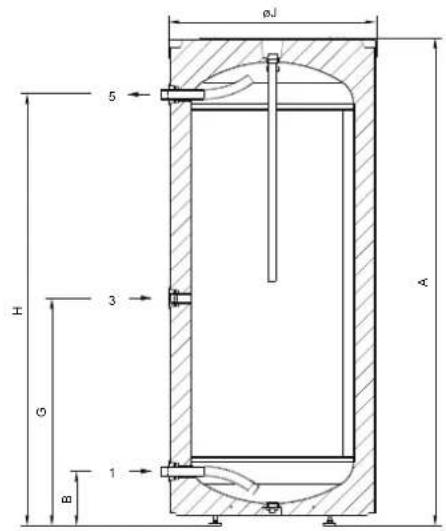
| VLG 200A-G | VLG 300B-G | VLG 400B-G | |
| A [mm] | 1535 | 1590 | 1915 |
| B [mm] | 180 | 175 | 250 |
| G [mm] | 780 | 740 | 990 |
| H [mm] | 1355 | 1410 | 1675 |
| I [mm] | 365 | 320 | 400 |
| J [mm] | 580 | 680 | 760 |
| 1 | G 3/4 | G1 | G1 |
| 3 | G 3/4 | G 3/4 | G 3/4 |
| 5 | G 3/4 | G1 | G1 |
LEGENDA
1 Dovod hladne vode
3 Cirkulacijski vod
5 Odvod tople vode
PRIKLJUČIVANJE NA VODOVOD
Priključivanje na vodovod napravite po oznakama za priključke iz prethodnog poglavlja.
Zbog sigurnosti je potrebno na dovodnu cev ugraditi sigurnosni ventil ili sigurnosnu navlaku koja sprečava povećanje pritiska u kotlu za više od 0,1 MPa (1 bar) preko nominalnog. Odvodni otvor na sigurnosnom ventilu mora da ima izlaz na atmosferski pritisak. Pri zagrevanju vode u bojleru se pritisak vode v kotlu povećava do granice koja je dozvoljena sigurnosnim ventilom. Pošto je vraćanje vode u vodovod onemogućeno može doći do njenog kapanja iz odvodnog otvora sigurnosnog ventila. Tu vodu možete da usmerite u odvod preko spremnika za vodu koji bi postavili ispod sigurnosnog ventila. Odvodna cev montirana ispod elementa za ispuštanje na sigurnosnom ventilu mora da bude nameštena u smeru pravo nadole i u sredini gde ne smrzava.
U slučaju da želite izbeći kapanje vode iz sigurnosnog ventila, morate na dovodnu cev ventila ugraditi ekspanzioni sud za sanitarnu vodu zapremine najmanje 5% zapremine bojlera.
Za pravilan rad sigurnosnog ventila potrebno je periodično izvoditi kontrole, odstranjivati kamenac i proveravati da sigurnosni ventil nije blokiran. Pri proveravanju pomeranjem ručke ili odvijanjem matice ventila (u zavisnosti od tipa ventila) morate da otvorite odvod iz sigurnosnog ventila. Prilikom toga kroz mlaznicu ventila za isticanje mora da priteče voda, što će značiti da je ventil besprekoran.
Sl. 3: Zatvoreni (kompresorski) sistem
LEGENDA
1 Ispusni ventil
2 Ekspanzioni sud
3 Sigurnosni ventil
a - Probni ventil
b - Nepovratni venti
natural_image
3D rendered mechanical component with cylindrical body and circular top, showing mounting holes and a central hub (no text or symbols)Sl. 4: Uklanjanje poklopca grejača
Sl. 5: Sheme električnih veza
LEGENDA
1 Priključne kleme
2 Termostat i dvopolni ili tropolni toplotni osigurač
3 Grejač
L Fazni provodnik
L1 Fazni provodnik
L2 Fazni provodnik
L3 Fazni provodnik
N Neutralni provodnik
± Zaštitni provodnik
Na gornjoj strani bojlera pod poklopcem su montirane dve cevi za pipaljke, gde se mogu ugraditi pipaljke za regulaciju sistemske veze bojlera sa drugim izvorima grejanja. Maksimalni prečnik pipaljki je 8 mm.
Sl. 6: Montaža pipaljki
UPOZORENJE: Pre svakog posega u unutrašnjost bojlera, morate ga obavezno isključiti iz električne mreže! Posege mogu da izvode samo osposobljena stručna lica.
PRIKLJUČIVANJE NA DRUGE IZVORE GREJANJA
Bojler omogućava zagrevanje sanitarne vode preko razmene toplote sa različitim izvorima energije (npr. centralno grejanje, sunčeva energija, ...).
The appliance may be used by children aged 8 and older and persons with physical, sensory or mental disabilities or lacking experience or knowledge, if they are under supervision or taught about safe use of the appliance and if they are aware of the potential dangers.
Children should not play with the appliance.
Children should not clean or maintain the appliance without supervision
The installation should be performed in accordance with the valid regulations and the instructions of the manufacturer. It should be performed by a professionally trained installation expert.
It is obligatory to install a safety valve with a rated pressure of 0.6 MPa (6 bar), 0.9 MPa (9 bar) or 1.0 MPa (10 bar) - see the label - on the inlet pipe of the hot water storage tank to prevent the elevation of pressure in the tank by more than 0.1 MPa (1 bar) above the rated pressure.
Water may drip from the outlet opening of the safety valve, so the outlet opening should be set to atmospheric pressure.
The outlet of the safety valve should be installed facing downwards and in a non-freezing area.
To ensure proper functioning of the safety valve, the user should perform regular controls to remove limescale and make sure the safety valve is not blocked.
Do not install a stop valve between the hot water storage tank and the safety valve, because it will impair the pressure protection of the storage tank!
Before connecting the heater to the power supply, the storage tank must be filled with water!
The storage tank is protected in case of failure of the operating thermostat with an additional thermal cut-out. In case of thermostat failure water in the storage tank may reach the temperature of up to 130^ C in accordance with safety standards. The possibility of such temperature overload should be taken into consideration in the execution of plumbing.
Should you choose to disconnect the power, the storage tank should be drained thoroughly before the onset of freezing conditions.
Water from the storage tank is drained through the inlet pipe of the tank. For this purpose, a special fitting (T-fitting) with an outlet valve must be mounted between the safety valve and the inlet pipe.
Please do not try to fix any defects of the storage tank on your own. Call the nearest authorised service provider.

Our products incorporate components that are both environmentally safe and harmless to health, so they can be disassembled as easily as possible and recycled once they reach their final life stage.
Recycling of materials reduces the quantity of waste and the need for production of raw materials (e.g. metals) which requires a substantial amount of energy and causes release of harmful substances. Recycling procedures reduce the consumption of natural resources, as the waste parts made of plastic and metal can be returned to various production processes.
For more information on waste disposal, please visit your waste collection centre or the store where the product was purchased
Dear buyer, thank you for purchasing our product.
PRIOR TO THE INSTALLATION AND FIRST USE OF THE HOT WATER STORAGE TANK, PLEASE READ THESE INSTRUCTIONS CAREFULLY.
This storage tank has been manufactured in compliance with the relevant Standards and tested by the relevant authorities as indicated by the Safety Certificate and the Electromagnetic Compatibility Certificate. The technical characteristics of the product are listed on the label attached to the protective cover.
The connection of the storage tank to the plumbing and power networks must be carried out by qualified staff only. All repairs and maintenance work in the interior of the storage tank, as well as limestone removal or testing or replacement of the corrosion protection anode, may only be carried out by an approved maintenance service provider.
The hot water storage tank is designed in a manner which allows using the following heating sources, via a heat exchanger:
• Central heating hot-water system,
- Solar power,
- Heating pump.
INSTALLATION
The heater should be installed in a dry room that is not subject to freezing conditions, preferably in the vicinity of other sources of heating (e.g. boiler room). Prior to installation screw on the enclosed adjustable legs. Level the storage tank longitudinally and transversally by rotating the adjustable legs.
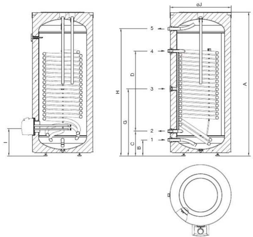
KEY
1 Cold water inflow
2 Medium outlet from the heat exchanger
3 Circulation conduit
4 Medium inflow into the heat exchanger
5 Hot water outflow
| VLG 200 A1-1G VLG 200 A3-1G VLG 300 B1-1G VLG 300 B2-1G VLG 300 C1-1G VLG 400 C1-1G | ||||||
| A 1535 1675 1590 1590 1445 1915 | ||||||
| B | 180 | 220 | 175 | 175 | 250 | 250 |
| C | 300 | 340 | 270 | 270 | 370 | 370 |
| D | 880 | 1015 | 890 | 890 | 610 | 1070 |
| G | 780 | 945 | 740 | 740 | 800 | 990 |
| H 1355 1435 1410 | 1410 1205 1675 | |||||
| I | 365 | 405 | 320 | 340 | 400 | 400 |
| J | 580 | 680 | 680 | 680 | 760 | 760 |
| 1 | G 3/4 | G 3/4 | G1 | G1 | G1 | G1 |
| 2 | G1 | G1 | G1 | G 5/4 | G 5/4 | G 5/4 |
| 3 | G 3/4 | G 3/4 | G 3/4 | G 3/4 | G 3/4 | G 3/4 |
| 4 | G1 | G1 | G1 | G 5/4 | G 5/4 | G 5/4 |
| 5 | G 3/4 | G 3/4 | G1 | G1 | G1 | G1 |
Image 1: Connection and installation dimensions of the storage tank [mm]
natural_image
Technical cross-sectional diagram of a heat exchanger or coiled spring assembly (no text or labels)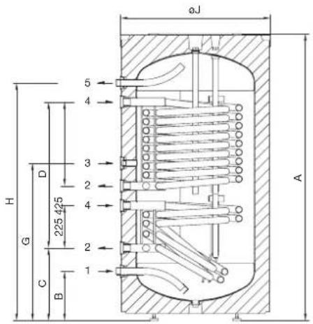
natural_image
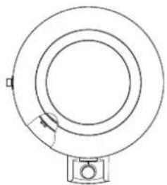
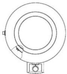
Technical line drawing of a circular mechanical component with a base mount (no text or symbols)KEY
1 Cold water inflow
2 Medium outlet from the heat exchanger
3 Circulation conduit
4 Medium inflow into the heat exchanger
5 Hot water outflow
| VLG 300 C1-2G | |
| A 1445 | |
| B 250 | |
| C 370 | |
| D 740 | |
| G 800 | |
| H 1205 | |
| I 400 | |
| J 760 | |
| 1 G1 | |
| 2 G5/4 | |
| 3 G 3/4 | |
| 4 G5/4 | |
| 5 G1 |
Image 2: Connection and installation dimensions of the storage tank [mm]
natural_image
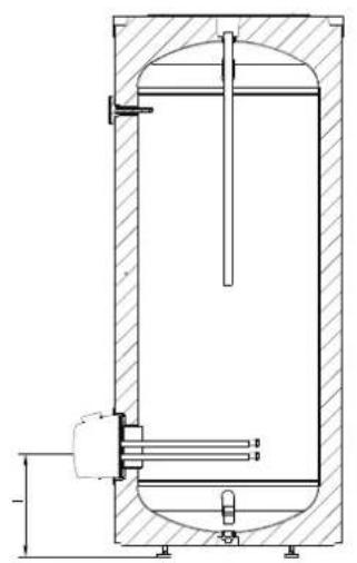
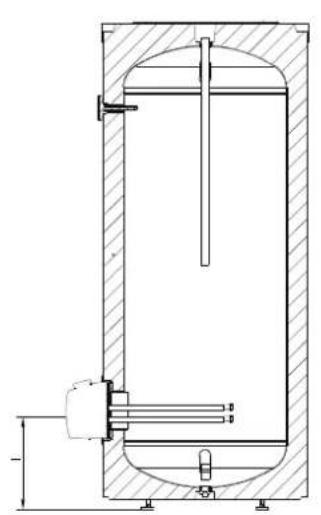
Technical line drawing of a vertical cylindrical tank with internal components and a side-mounted shaft (no text or symbols)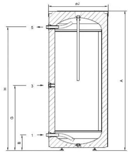
| VLG 200A-G | VLG 300B-G | VLG 400B-G | |
| A [mm] | 1535 | 1590 | 1915 |
| B [mm] | 180 | 175 | 250 |
| G [mm] | 780 | 740 | 990 |
| H [mm] | 1355 | 1410 | 1675 |
| I [mm] | 365 | 320 | 400 |
| J [mm] | 580 | 680 | 760 |
| 1 | G 3/4 | G1 | G1 |
| 3 | G 3/4 | G 3/4 | G 3/4 |
| 5 | G 3/4 | G1 | G1 |
KEY
1 Cold water inflow
3 Circulation conduit
5 Hot water outflow
CONNECTION TO THE WATER SUPPLY
Connection to water supply should be made according to the markings for the connections, as defined in the previous Chapter.
For safety reasons the supply pipe must be fitted with a safety valve or, alternatively, a valve of the safety class that prevents the pressure in the tank from exceeding the nominal pressure by more than 0.1 MPa (1 bar). The outlet opening on the safety valve must be equipped with an outlet for atmospheric pressure. The heating of water in the storage tank causes the pressure in the tank to increase to the level set by the safety valve. As the water cannot return to the water supply system, this can result in dripping from the outlet opening of the safety valve. The drip can be piped to a drain by installing a catching unit just below the safety valve. The drain installed below the safety valve outlet must be piped down vertically and placed in an environment that is free from the onset of freezing conditions.
In case you want to avoid water dripping from the safety valve, an expansion tank for domestic water with at least 5 % of the volume of the storage tank should be installed on the inlet pipe of the storage tank.
To ensure proper functioning of the safety valve, the user should perform regular controls to remove limescale and make sure the safety valve is not blocked. To check the valve, open the outlet of the safety valve by turning the handle or unscrewing the nut of the valve (depending on the type of valve). The valve is operating properly if the water comes out of the nozzle when the outlet is open.
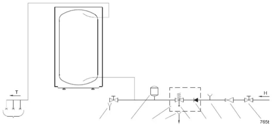
Image 3: Closed (pressure) system
KEY
1 Drain valve
2 Expansion tank
3 Safety valve
a - Test valve
b - Non-return valve
4 Funnel outlet to the drain
5 Test unit
6 Pressure-reducing valve
7 Stop valve
8 Pressure mixer taps
H Cold water
T Hot water
The storage tank can be connected to the domestic water supply network without a pressure regulator if the pressure in the network is lower than the nominal pressure (see the label). If the pressure in the network exceeds the nominal pressure, a pressure regulator must be installed.
CONNECTION TO THE POWER SUPPLY NETWORK
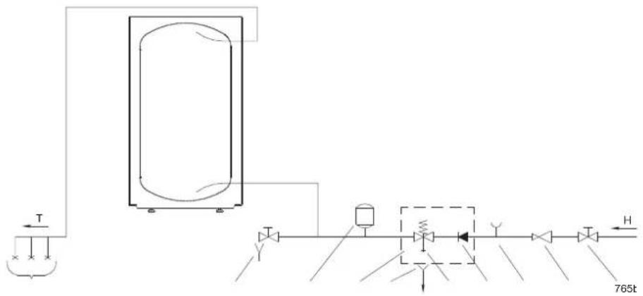
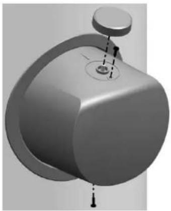
Before connecting the storage tank to the power supply network, a connection cable with a minimum cross-section of at least 1.5 mm ^2 (H05VV-F 3G 1.5 mm ^2 ) for a 3kW-heating element and 2.5 mm ^2 for a 6kW-heating element (H05VV-F 5G 2.5 mm ^2 ) must be installed in it and the protection cover must be removed.
This is done by pulling out the knob on the thermostat axis and unscrewing two screws.
An all-pole disconnect device must be installed in the electric installation to comply with the National Installation Regulations.
natural_image
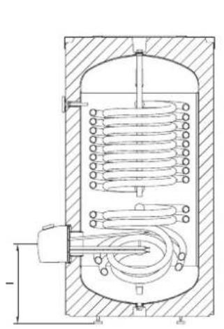
3D rendered mechanical component with cylindrical body and circular top, showing internal features and mounting holes (no text or symbols)Image 4: Removal of heater cover
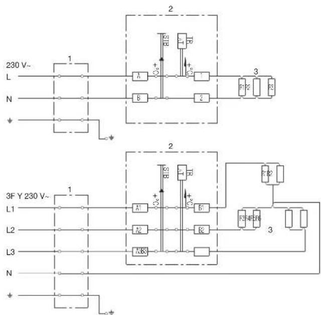
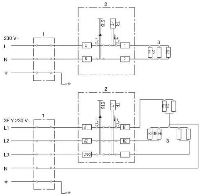
Image 5: Schemes of electric installations
KEY
1 Connection terminal
2 A thermostat and a bipolar or tripolar thermal cut-out
3 Heater
L Live conductor
L1 Live conductor
L2 Live conductor
L3 Live conductor
N Neutral conductor
± Earthing conductor
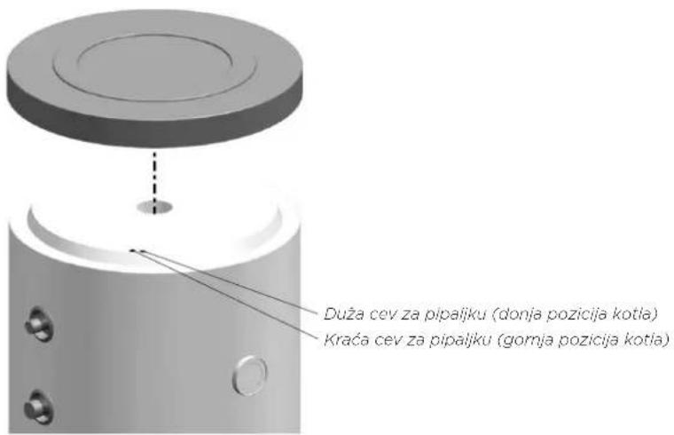
On the upper side of the storage tank there are two sensor tubes for mounting the sensors for regulation of the system connection of the hot water storage tank to other heating sources. The maximum diameter of the sensors is 8 mm.

Image 6: Installation of sensors
WARNING: Before any intervention into the interior of the storage tank disconnect it from the power supply! All interventions must be carried out by qualified staff only!
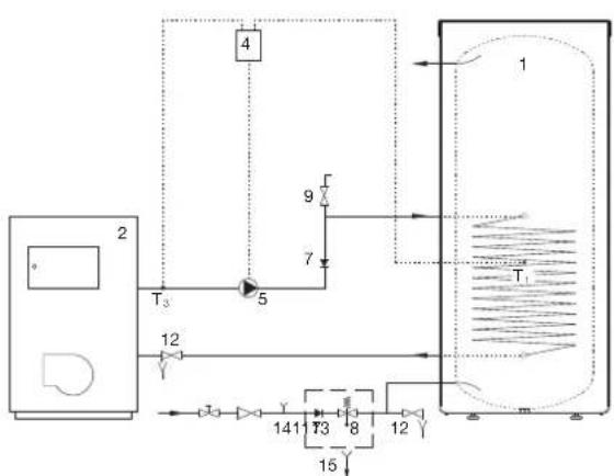
CONNECTION TO ALTERNATIVE SOURCES OF HEATING
The hot water storage tank enables the water for sanitary use to be heated by alternative sources of energy (e.g. central heating, solar power etc.) by installing a Heat Exchanger.
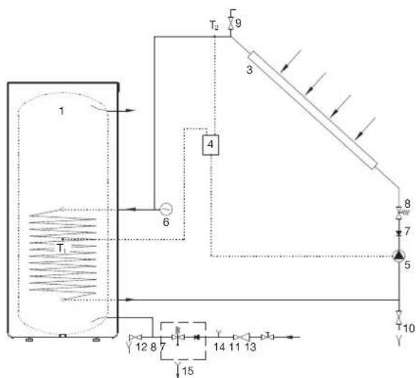
Examples of connecting the hot water storage tank to various sources of heating are shown in the drawings below.
KEY
1 Hot water storage tank
2 Central heating hot-water system
3 Solar panel
4 Differential thermostat with sensors (T1, T2, T3, T4)
5 Bypass pump
6 Expansion tank
7 Non-return valve
8 Safety valve
9 Air relief valve
10 Fill/drain valve
11 Reduction valve
12 Drain valve
13 Stop valve
14 Test unit
15 Funnel outlet to the drain
flowchart
graph TD
    A["1"] --> B["T1"]
    B --> C["6"]
    C --> D["T2"]
    D --> E["9"]
    E --> F["3"]
    F --> G["4"]
    G --> H["5"]
    H --> I["8"]
    I --> J["7"]
    J --> K["10"]
    K --> L["14"]
    L --> M["13"]
    M --> N["12"]
    N --> O["8"]
    O --> P["7"]
    P --> Q["15"]
    Q --> R["14"]
    R --> S["13"]
Image 7: Connection to solar panels
flowchart
graph TD
    A["Thermal System"] --> B["Heat Exchanger"]
    B --> C["T1"]
    B --> D["T2"]
    B --> E["T3"]
    B --> F["T4"]
    B --> G["T5"]
    B --> H["T6"]
    B --> I["T7"]
    B --> J["T8"]
    B --> K["T9"]
    B --> L["T10"]
    style A fill:#f9f,stroke:#333
    style B fill:#ccf,stroke:#333
    style C fill:#cfc,stroke:#333
    style D fill:#fcc,stroke:#333
    style E fill:#cff,stroke:#333
    style F fill:#ffc,stroke:#333
    style G fill:#cfc,stroke:#333
    style H fill:#fcc,stroke:#333
    style I fill:#cfc,stroke:#333
    style J fill:#fcc,stroke:#333
    style K fill:#cfc,stroke:#333
Image 8: Connection to the central heating hot-water system
The hot water storage tank is ready for use once it has been connected to water and electricity and other heating sources. The usual main sources for heating domestic water are central heating or solar power; in this case any regulation of water heating is performed in the heating system.
The built-in electric heating element is designed for backup heating of water only. The temperature is set by turning the knob in a clockwise direction to reach the desired temperature level.
* - Protection against freezing, temperature around 10 °C.
- Water temperature around 35 °C.
eco - Water temperature around 55 °C.
- Water temperature around 85 °C.
The thermometer shows the in-situ temperature, whereas by turning the knob on the thermostat the water temperature in the lower part of the storage tank is set. Thus, these two temperatures may vary.
In case of exposure to sub-zero temperatures, the water should be drained from the storage tank thoroughly before the onset of freezing conditions. Water from the storage tank is drained through the inlet pipe of the storage tank. For this purpose, a special fitting (T-fitting) with an outlet valve must be mounted between the safety valve and the inlet pipe. Before discharge make sure the storage tank is disconnected from the power supply, close the inlet of cold water into the storage tank, open the hot water tap on the connected mixer tap and wait for the water in the storage tank to cool down. After discharging through the inlet pipe there is still some water left in the storage tank.
The external parts of the water heater may be cleaned with a soft cloth and mild cleaning fluids. Do not use cleaning fluids containing alcohol or abrasives.
Regular preventive maintenance inspections ensure faultless performance and long life of your storage tank. Tank Warranty is subject to regular inspections of the wear of the protective anode. The period between individual regular inspections should not be longer than specified in the Guarantee statement. Inspection should be carried out by an authorised maintenance service provider recording the inspection on the Guarantee Certificate of the product. During the inspection, the wear of the corrosion protection anode will be inspected and any limestone built up in the interior of the storage tank, depending on the quality, quantity and temperature of used water, will be removed as required. After inspecting the storage tank, the maintenance service provider will also recommend the date of the next inspection according to the ascertained status.
Please do not try to fix any defects of the storage tank on your own. Call the nearest authorised service provider.
TECHNICAL CHARACTERISTICS OF THE APPLIANCE
| Type * | VLG 200 A1-1G | VLG 200 A3-1G | VLG 300 B1-1G | VLG 300 B2-1G | VLG 300 C1-1G | VLG 300 C1-2G | VLG 400 C1-1G | |
| Energy efficiency class ^1 | C B C C B B B | |||||||
| Standing loss S ^2) | [W] 70,8 | 58,3 | 88,8 | 68 | 68 | 71,9 | ||
| Storage volume [I] 184 | 190,3 | 275,5 | 262 | 283,7 | 283,7 | 396 | ||
| Rated pressure [MPa (bar)] 0,6 (6); 0,9 (9); 1.0 (10) | ||||||||
| Weight/filled with water | [kg] | 97 / 281 | 115 / 305 | 140 / 416 | 165 / 427 | 165/449 | 170/454 | 230/626 |
| Anti-corrosion protection of tank Enamelled/Mg anode | • / • | • / • | • / • | • / • | • / • | • / • | • / • | |
| Protection class | I | |||||||
| Degree of protection | IP24 | |||||||
| Heat exchanger surface | [m ^2 ] | 2,0 | 2,3 | 2,5 | 4,0 | 3,45 | 1,05 + 2,4 | 6,15 |
| Temperature of the heating medium in the heat exchanger | [°C] | < 95 | ||||||
| Insulation thickness | [mm] | 60 | 110 | 67 | 67 | 75 | 75 | 75 |
| Heat loss ^2) | [kWh/24h] | 1,7 | 1,4 | 2,1 | 2,1 | 1,6 | 1,6 | 1,7 |
| Maximum diameter of sensors | [mm] | ø8 | ||||||
* If there is no letter G in the type designation, the appliance does not include the electric heater.
^1 Commission Regulation EU 812/2013
2) Tested pursuant to EN 12897:2006
| Model | VLG 200A1-1G3 | VLG 200A3-1G3 | VLG 300B1-1G3 | VLG 300B2-1G3 | VLG 300B1-1G6 | VLG 300B2-1G6 | |
| Connected load | [W] | 3000 | 6000 | ||||
| Voltage | [V-] | 230 | 400 | ||||
| Model | VLG 300C1-1G3 | VLG 300C1-2G3 | VLG 400C1-1G3 | VLG 300C1-1G6 | VLG 300C1-2G6 | VLG 400C1-1G6 | |
| Connected load | [W] | 3000 | 6000 | ||||
| Voltage | [V-] | 230 | 400 | ||||
| Type | VLG 200 A-G | VLG 300 B-G | VLG 400 C-G | |
| Use profile | XL | XL | XL | |
| Energy efficiency class1 | C | C | C | |
| Energy efficiency of water heating ηwh1) | [%] | 38,1 | 38,0 | 38,1 |
| Annual electrical energy consumption1) | [kWh] | 4399 | 4412 | 4400 |
| Daily electrical energy consumption2) | [kWh] | 20,317 | 20,397 | 20,328 |
| Set thermostat temperature | "eco" | "eco" | "eco" | |
| Potential safety measures (assembly, installation, maintenance) | Compulsory use of a safety valve with the pressure connection. | |||
| Smart value | 0 | 0 | 0 | |
| Storage volume | [l] | 203 | 319 | 449 |
| Mixed water at 40 °C V40 2) | [l] | 305 | 508 | 712 |
| Rated pressure | [MPa (bar)] | 0,6 (6); 0,9 (9); 1,0 (10) | ||
| Weight/filled with water | [kg] | 63/265 | 97/397 | 230/626 |
| Anti-corrosion protection of tank Enamelled/Mg anode | • / • | • / • | • / • | |
| Protection class | 1 | |||
| Degree of protection | IP24 | |||
| Insulation thickness | [mm] | 60 | 67 | 75 |
| Heat loss3) | [kWh/24h] | 1,7 | 2,1 | 1,7 |
| Heating time from 10 °C to 65 °C | [h] | 4 % | 6 % | 4 % |
^1 directive 812/2013; EN 50440
2) EN 50440
^31 Tested pursuant to SIST EN 60379:2005
| Model | VLG 200 A-G3 | VLG 300 B-G3 | VLG 400 C-G6 | |
| Connected load | [W] | 3000 | 6000 | |
| Voltage | [V°] | 230 | 400 | |
WE RESERVE THE RIGHT TO ANY MODIFICATIONS NOT AFFECTING THE FUNCTIONALITY OF THE APPLIANCE.
The instructions for use are also available on our website http://www.gorenje.com.
