
MY8-SDI-D - Audio/Video Interface Card YAMAHA - Free user manual and instructions
Find the device manual for free MY8-SDI-D YAMAHA in PDF.

| Product type | Audio/video interface card |
| Brand | YAMAHA |
| Model | MY8-SDI-D |
| Main functions | 8 SDI inputs and 8 outputs with embedded digital audio |
| Connectivity | BNC connectors (75 ohms) for SDI video signals |
| Supported video formats | HD-SDI (1.485 Gbps) and SD-SDI (270 Mbps) |
| Audio resolution | 24-bit, 48 kHz |
| Power supply | Powered via YAMAHA host console bus |
| Dimensions (approx.) | 12.7 x 9.5 x 3.8 cm (expansion card) |
| Weight (approx.) | 0.25 kg |
| Compatibility | YAMAHA digital consoles with MY slot (CL, QL, DM7, etc.) |
| Maintenance and cleaning | Wipe with a dry, lint-free cloth. Do not use solvents. |
| Safety | Follow ESD precautions during installation. Disconnect console power before insertion. |
| Spare parts and repairability | No user-serviceable parts. Contact an authorized YAMAHA service center. |
| General information | Compliant with ICES-003 (Canada) for Class B digital device. |
Frequently Asked Questions - MY8-SDI-D YAMAHA
User questions about MY8-SDI-D YAMAHA
0 question about this device. Answer the ones you know or ask your own.
Ask a new question about this device
Download the instructions for your Audio/Video Interface Card in PDF format for free! Find your manual MY8-SDI-D - YAMAHA and take your electronic device back in hand. On this page are published all the documents necessary for the use of your device. MY8-SDI-D by YAMAHA.
USER MANUAL MY8-SDI-D YAMAHA
HD-SDI DEMULTIPLEXER CARD MY8-SDI-D
Owner's Manual
Bedienungsanleitung
Mode d'emploi
This product, when installed as indicated in the instructions contained in this manual, meets FCC requirements. Modifications not expressly approved by Yamaha may void your authority, granted by the FCC, to use the product.
-
IMPORTANT: When connecting this product to accessories and/or another product use only high quality shielded cables. Cable/s supplied with this product MUST be used. Follow all installation instructions. Failure to follow instructions could void your FCC authorization to use this product in the USA.
-
NOTE: This product has been tested and found to comply with the requirements listed in FCC Regulations, Part 15 for Class "B" digital devices. Compliance with these requirements provides a reasonable level of assurance that your use of this product in a residential environment will not result in harmful interference with other electronic devices. This equipment generates/uses radio frequencies and, if not installed and used according to the instructions found in the users manual, may cause interference harmful to the operation of other electronic
devices. Compliance with FCC regulations does not guarantee that interference will not occur in all installations. If this product is found to be the source of interference, which can be determined by turning the unit "OFF" and "ON", please try to eliminate the problem by using one of the following measures:
Relocate either this product or the device that is being affected by the interference.
Utilize power outlets that are on different branch (circuit breaker or fuse) circuits or install AC line filter/s.
In the case of radio or TV interference, relocate/reorient the antenna. If the antenna lead-in is 300 ohm ribbon lead, change the lead-in to co-axial type cable.
If these corrective measures do not produce satisfactory results, please contact the local retailer authorized to distribute this type of product. If you can not locate the appropriate retailer, please contact Yamaha Corporation of America, Electronic Service Division, 6600 Orangethorpe Ave, Buena Park, CA90620
The above statements apply ONLY to those products distributed by Yamaha Corporation of America or its subsidiaries.
* This applies only to products distributed by YAMAHA CORPORATION OF AMERICA. (class B)
CANADA
This device complies with Part 15 of the FCC Rules. Operation is subject to the following two conditions:
(1) this device may not cause harmful interference, and (2) this device must accept any interference received, including interference that may cause undesired operation.
PRECAUTIONS
PLEASE READ CAREFULLY BEFORE PROCEEDING
* Please keep this manual in a safe place for future reference.

WARNING
Always follow the basic precautions listed below to avoid the possibility of serious injury or even death from electrical shock, short-circuiting, damages, fire or other hazards. These precautions include, but are not limited to, the following:
- Before installing the card in an audio device please check to make sure that the device is compatible with the card and check possible restrictions regarding the maximum number of Yamaha and third-party expansion cards that can be simultaneously installed. Refer to the owner's manual supplied with the audio device, and/or the Yamaha Pro Audio web site at: http://www.yamahaproaudio.com/
- Do not install the card in any Yamaha products not specified by Yamaha for use with the card to avoid possible electrical shock, fire, or equipment damage.
- Do not attempt to disassemble or modify the card. Do not apply excessive force to card connectors or other card components. Mishandling of the card may lead to shock, fire hazard, or equipment failure.
- Be sure to disconnect the power cable of the host device before installing the card and connecting/disconnecting the cables (in order to eliminate shock hazard, undesired noise, and avoid equipment damage).
- Turn off all peripheral devices connected to the host device before installation, and unplug all related cables (in order to eliminate shock hazard, undesired noise, and avoid equipment damage).

CAUTION
Always follow the basic precautions listed below to avoid the possibility of physical injury to you or others, or damage to the device or other property. These precautions include, but are not limited to, the following:
- Be sure to properly ground the host device to prevent electrical shock and/or malfunction.
- Do not touch the metallic leads (pins) of the circuit board when handling the card. The pins are sharp and may cause hand cuts.
- Wear a pair of heavy gloves during installation to avoid scratching or cutting your hands on sharp edges.
- Avoid touching exposed connectors and metal parts to minimize the possibility of bad connections.
- Drain all static electricity from your clothing and body before handling the card. Static electricity can damage the card. Touch an exposed metal part of the host device or other grounded object beforehand.
- Do not drop the card or subject it to physical shock as this can result in breakage and/or malfunction.
- Do not drop screws or other small parts inside the card. If power is applied while screws or similar metal objects are loose inside the unit the card may malfunction or be damaged. If you cannot retrieve dropped objects yourself, refer the problem to qualified Yamaha service personnel.
Yamaha cannot be held responsible for damage caused by improper use or modifications to the device, or data that is lost or destroyed.
- The illustrations as shown in this manual are for instructional purposes only, and may be different from the ones on your equipment.
- The company names and product names in this manual are the trademarks or registered trademarks of their respective companies.
Information for Users on Collection and Disposal of Old Equipment

natural_image
Symbol of a trash bin crossed out by two crossed lines, with no text or labels present.This symbol on the products, packaging, and/or accompanying documents means that used electrical and electronic products should not be mixed with general household waste.
For proper treatment, recovery and recycling of old products, please take them to applicable collection points, in accordance with your national legislation and the Directives 2002/96/EC.
By disposing of these products correctly, you will help to save valuable resources and prevent any potential negative effects on human health and the environment which could otherwise arise from inappropriate waste handling.
For more information about collection and recycling of old products, please contact your local municipality, your waste disposal service or the point of sale where you purchased the items.
[For business users in the European Union]
If you wish to discard electrical and electronic equipment, please contact your dealer or supplier for further information.
[Information on Disposal in other Countries outside the European Union]
This symbol is only valid in the European Union. If you wish to discard these items, please contact your local authorities or dealer and ask for the correct method of disposal.
European models
Purchaser/User Information specified in EN55103-1 and EN55103-2.
Conforms to Environments: E1, E2, E3 and E4
Introduction
Thank you for choosing the Yamaha MY8-SDI-D HD-SDI ^(*) De-multiplexer card.
The MY8-SDI-D is an HD-SDI de-multiplexer Mini-YGDAI card for use with compatible Yamaha professional audio equipment. The card enables you to input up to two audio groups (four channels per group; total eight channels) to a host device, by selecting them from four audio groups (total 16 channels) that are multiplexed into a HD-SDI signal.
To take full advantage of the superior functionality of the MY8-SDI-D and enjoy years of trouble-free use, please read this manual before you begin using the product.
* This card does not support SD-SDI.
About the host devices in which the MY8-SDI-D can be installed
Before installing the card in a host device, please refer to the Yamaha Pro Audio web site for the latest information on the compatible host devices in which the card can be installed. Yamaha Pro Audio website:
http://www.yamahaproaudio.com/
Installation information
Please refer to the owner's manual supplied with the host device for installation information. In addition to securing the card in place, the fixing screws at the left and right of the card function as electrical grounds. Be sure to screw them in tightly.
Accessories
Owner's Manual
Part Names and Functions
Panel
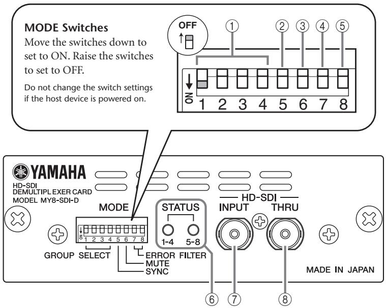
① GROUP SELECT Switches (SW1-4)
Set these switches to ON to select the following embedded audio groups. Up to two groups of audio can be input to slot channels 1-4 and 5-8.
| SW1 | SW2 | SW3 | SW4 |
| Group1 (ch1–4) | Group2 (ch5–8) | Group3 (ch9–12) | Group4 (ch13–16) |
Note:
- If only one switch is set to ON, audio will be input to channels 1-4, but not to channels 5-8.
- If all four switches are set to OFF, no audio will be input to any channels.
- If more than two GROUP SELECT switches are set to ON, only the first two switches (in ascending order) will actually be on.
For example, if SW2, SW3, and SW4 are set to ON, Group 2 and Group 3 audio will be input to slot channels 1-4 and 5-8 respectively, and Group 4 audio will not be input.

② SYNC Switch (SW5)
Typically set this switch to OFF.
OFF: An audio clock will be generated based on the phase data of the embedded audio.
ON: An audio clock will be generated from video signals.
If the SYNC switch is set to ON, the phase between audio groups may not be identical. Set this switch to ON only if you cannot input audio with the switch set to OFF.
③ MUTE Switch (SW6)
Typically set this switch to OFF.
OFF: Audio will not be muted regardless of whether or not an HD-SDI input error is detected.
ON: Audio will be muted if an HD-SDI input error is detected (the STATUS LED lights up in a color other than green). Use this setting if you want to use muted audio to indicate an error.
Note:
Keep in mind that connecting or disconnecting a cable may cause noise even if this switch is set to ON.
④ ERROR FILTER Switch (SW7)
Typically set this switch to OFF. This switch is used to analyze the causes of errors.
OFF: A filter is not applied to a detected HD-SDI input error. Each STATUS LED indicates the type of all HD-SDI input errors as shown in the list below. Audio will be muted if SW6 is set to ON.
HD-SDI Input Errors
| Details | ON | OFF |
| Video standard error | error | error |
| Chromaticity checksum error | — | error |
| Brightness checksum error | — | error |
| Chromaticity CRC error | — | error |
| Brightness CRC error | — | error |
| Line number error | — | error |
| Start of active line (SAV) code word error | — | error |
| End of active line (EAV) code word error | — | error |
ON: A filter is applied to a detected HD-SDI input error (excluding the video standard error). The STATUS LEDs will not indicate an error status. Audio will be input to the slot channels, and will not be muted regardless of the SW6 setting.
⑤ ERROR FILTER Switch (SW8)
Typically set this switch to OFF. This switch is used to analyze the causes of errors.
OFF: A filter is not applied to a detected embedded audio error. Each STATUS LED indicates the type of error as shown in the list below. Audio will be muted if SW6 is set to ON.
Embedded Audio Errors
| Details | ON | OFF |
| UNLOCK | error | error |
| Presence of any audio group packet | error | error |
| CRC error of video signal sent to audio block | error | error |
| Phase data error of the selected audio group(s) | error | error |
| Data block number error | — | error |
| Parity error in audio packet | — | error |
| Error correcting code error | — | error |
| Checksum error in the selected audio group(s) | — | error |
ON: A filter is applied to a detected embedded audio error marked with a [—] in the list above. The STATUS LEDs will not indicate the status of errors marked
with [—] in the list. Audio will be input to the slot channels, and will not be muted regardless of the SW6 setting.
⑥ STATUS LED
[1-4] LED: Indicates the status of channels 1 through 4
[5-8] LED: Indicates the status of channels 5 through 8
| LED Indicator | Description of Status (Error) |
| Off (dark) | No SDI-input signal is detected or being input. Alternatively, no audio group has been selected. |
| Red flash ( Slow^*1 ) | SD-SDI signals are being input. |
| Orange flash ( Slow^*1 ) | An SDI input error has occurred. |
| Red | Embedded audio is unlocked. |
| Red flash ( Fast^*2 ) | No selected audio group packet exists. |
| Orange flash ( Fast^*2 ) | A CRC error has occurred in the video signal sent to the audio block. |
| Orange | An error has occurred in the embedded audio packet. |
| Green | Embedded audio is locked correctly. |
*1. Flashes approximately once per second.
*2. Flashes approximately four times per second.
Note:
- If an error that cannot be attributed to any channel has occurred, STATUS LEDs [1-4] and [5-8] will provide the same indication.
- If multiple errors have occurred simultaneously, the priority of the STATUS LEDs indication is the descending order of the list above.
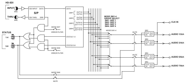
⑦ HD-SDI INPUT Connector
This is a BNC connector that inputs HD-SDI signals.
⑧ HD-SDI THRU Connector
This is a BNC connector that outputs non re-clock and active thru HD-SDI signals.
Note:
We recommend that you use a 5C-FB coaxial cable ^* , or a coaxial cable that features excellent performance equivalent to that of the 5C-FB cable. The 5C-FB cable transmits HD-SDI signals over a distance of up to 100 meters.
* The attenuation of the 5C-FB cable at 750 MHz is approximately 20dB/100m.
■ Dip Switches (SW2)
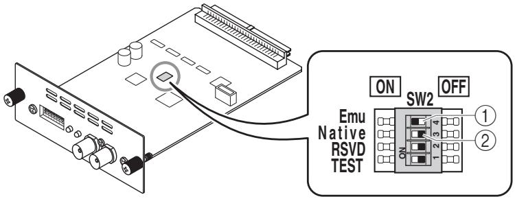
① Emu Switch
If you set this switch to ON and the Native switch to OFF, the host device will recognize the card as a Yamaha MY8-AD96 AD card.
② Native Switch
If you use the card in a future host device that supports the Native mode, setting this switch to ON and the Emu switch to OFF will enable you to make best use of the MY8-SDI-D function.
Emu/Native Switch Settings
| Emu | Native | Function |
| ON | OFF | MY8-AD96 Emulation mode |
| OFF | ON | MY8-SDI-D Native mode |
| ON | ON | Reserved |
| OFF | OFF | Reserved |
Leave the RSVD and TEST switches set to OFF. Otherwise, the unit will not operate properly.
About the Word Clock Settings
You cannot assign the MY8-SDI-D as the master clock.
If you need to synchronize the host device to a house sync signal (external digital system), use the WORD CLOCK IN connector to set the master clock of the host device to WORD CLOCK IN.
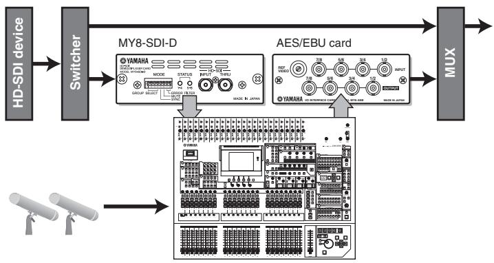
Connection Example
flowchart
graph LR
    A["HD-SDI device"] --> B["Switcher"]
    B --> C["MY8-SDI-D"]
    C --> D["AES/EBU card"]
    D --> E["MUX"]
    F["Sensor 1"] --> G["Sensor 2"]
    G --> H["Sensor 3"]
    H --> I["Sensor 4"]
    I --> J["Sensor 5"]
    J --> K["Sensor 6"]
    K --> L["Sensor 7"]
    L --> M["Sensor 8"]
    M --> N["Sensor 9"]
    N --> O["Sensor 10"]
    O --> P["Sensor 11"]
    P --> Q["Sensor 12"]
    Q --> R["Sensor 13"]
    R --> S["Sensor 14"]
    S --> T["Sensor 15"]
    T --> U["Sensor 16"]
    U --> V["Sensor 17"]
    V --> W["Sensor 18"]
    W --> X["Sensor 19"]
    X --> Y["Sensor 20"]
    Y --> Z["Sensor 21"]
    Z --> AA["Sensor 22"]
    AA --> AB["Sensor 23"]
    AB --> AC["Sensor 24"]
    AC --> AD["Sensor 25"]
    AD --> AE["Sensor 26"]
    AE --> AF["Sensor 27"]
    AF --> AG["Sensor 28"]
    AG --> AH["Sensor 29"]
    AH --> AI["Sensor 30"]
    AI --> AJ["Sensor 31"]
    AJ --> AK["Sensor 32"]
    AK --> AL["Sensor 33"]
    AL --> AM["Sensor 34"]
    AM --> AN["Sensor 35"]
    AN --> AO["Sensor 36"]
    AO --> AP["Sensor 37"]
    AP --> AQ["Sensor 38"]
    AQ --> AR["Sensor 39"]
    AR --> AS["Sensor 40"]
    AS --> AT["Sensor 41"]
    AT --> AU["Sensor 42"]
    AU --> AV["Sensor 43"]
    AV --> AW["Sensor 44"]
    AW --> AX["Sensor 45"]
    AX --> AY["Sensor 46"]
    AY --> AZ["Sensor 47"]
    AZ --> BA["Sensor 48"]
    BA --> BB["Sensor 49"]
    BB --> BC["Sensor 50"]
    BC --> BD["Sensor 51"]
    BD --> BE["Sensor 52"]
    BE --> BF["Sensor 53"]
    BF --> BG["Sensor 54"]
    BG --> BH["Sensor 55"]
    BH --> BI["Sensor 56"]
    BI --> BJ["Sensor 57"]
    BJ --> BK["Sensor 58"]
    BK --> BL["Sensor 59"]
    BL --> BM["Sensor 60"]
    BM --> BN["Sensor 61"]
    BN --> BO["Sensor 62"]
    BO --> BP["Sensor 63"]
    BP --> BQ["Sensor 64"]
    BQ --> BR["Sensor 65"]
    BR --> BS["Sensor 66"]
    BS --> BT["Sensor 67"]
    BT --> BU["Sensor 68"]
    BU --> BV["Sensor 69"]
    BV --> BW["Sensor 70"]
    BW --> BX["Sensor 71"]
    BX --> BY["Sensor 72"]
    BY --> BZ["Sensor 73"]
    BZ --> CA["Sensor 74"]
    CA --> CB["Sensor 75"]
    CB --> CC["Sensor 76"]
    CC --> CD["Sensor 77"]
    CD --> CE["Sensor 78"]
    CE --> CF["Sensor 79"]
    CF --> CG["Sensor 80"]
    CG --> CH["Sensor 81"]
    CH --> CI["Sensor 82"]
    CI --> CJ["Sensor 83"]
    CJ --> CK["Sensor 84"]
    CK --> CL["Sensor 85"]
    CL --> CM["Sensor 86"]
    CM --> CN["Sensor 87"]
    CN --> CO["Sensor 88"]
    CO --> CP["Sensor 89"]
    CP --> CQ["Sensor 90"]
    CQ --> CR["Sensor 91"]
    CR --> CS["Sensor 92"]
    CS --> CT["Sensor 93"]
    CT --> CU["Sensor 94"]
    CU --> CV["Sensor 95"]
    CV --> CW["Sensor 96"]
    CW --> CX["Sensor 97"]
    CX --> CY["Sensor 98"]
    CY --> CZ["Sensor 99"]
Appendix
Specifications
- HD-SDI input
| SDI format | SMPTE 292M (1.485Gbps, 1.485/1.001Gbps) |
| Embedded audio | SMPTE 299M |
| Resolution | 24bit |
| Sampling frequency | 48kHz |
| Input level | 800mV ± 10% |
| Input Impedance | 75ohm |
| Connector | BNC type |
- HD-SDI output
| Output signal | non re-clock, active thru output |
| Output level | 800mV ± 10% |
| Output impedance | 75ohm |
| Connector | BNC type |
- Supported format
| 720p 50 | 720p 59.94 | 720p 60 |
| 1080i 50 | 1080i 59.94 | 1080i 60 |
| 1080p 25 | 1080p 29.97 | 1080p 30 |
| 1080p 24 | 1080p 23.97 | |
| 1080sF 24 | 1080sF 23.98 | |
| 1035i 59.94 | 1035i 60 |
■ Block Diagram
flowchart
graph TD
    A["HD-SDI INPUT"] --> B["SDI INPUT"]
    C["THRU"] --> D["SDI THRU"]
    B --> E["S/P"]
    D --> E
    E --> F["DATA"]
    F --> G["MODE SW7"]
    F --> H["MODE SW8"]
    F --> I["ERROR FILTER"]
    G --> J["STATUS 1-4"]
    H --> K["STATUS 5-8"]
    I --> L["STATUS 1-4"]
    M["STATUS 1-4"] --> N["MUTE"]
    O["STATUS 5-8"] --> P["MUTE"]
    Q["MODE SW6"] --> R["MUTE"]
    S["MODE SW7"] --> T["MUTE"]
    U["MODE SW8"] --> V["MUTE"]
    W["MODE SW9"] --> X["MUTE"]
    Y["MODE SW10"] --> Z["MUTE"]
    AA["MODE SW11"] --> AB["MUTE"]
    AC["MODE SW12"] --> AD["MUTE"]
    AE["MODE SW13"] --> AF["MUTE"]
    AG["MODE SW14"] --> AH["MUTE"]
    AI["MODE SW15"] --> AJ["MUTE"]
    AK["MODE SW16"] --> AL["MUTE"]
    AM["MODE SW17"] --> AN["MUTE"]
    AO["MODE SW18"] --> AP["MUTE"]
    AQ["MODE SW19"] --> AR["MUTE"]
    AS["MODE SW20"] --> AT["MUTE"]
    AU["MODE SW21"] --> AV["MUTE"]
    AW["MODE SW22"] --> AX["MUTE"]
    AY["INPUT"] --> AZ["BNC"]
    BA["THRU"] --> BB["BNC"]
    BC["STATUS 1-4"] --> BD["MUTE"]
    BE["STATUS 5-8"] --> BF["MUTE"]
    BG["MODE SW6"] --> BH["MUTE"]
    BI["MODE SW7"] --> BJ["MUTE"]
    BK["MODE SW8"] --> BL["MUTE"]
    BM["MODE SW9"] --> BN["MUTE"]
    BO["MODE SW10"] --> BP["MUTE"]
    BQ["MODE SW11"] --> BR["MUTE"]
    BS["MODE SW12"] --> BT["MUTE"]
    BU["MODE SW13"] --> BV["MUTE"]
    BW["MODE SW14"] --> BX["MUTE"]
    BY["MODE SW15"] --> BZ["MUTE"]
    CA["MODE SW16"] --> CB["MUTE"]
    CC["MODE SW17"] --> CD["MUTE"]
    DD["MODE SW18"] --> DE["MUTE"]
    FD["MODE SW19"] --> FDZ["MUTE"]
    DG["MODE SW20"] --> DGX["MUTE"]
    DGY["MODE SW21"] --> DGZ["XCLK CLK IN OUT"]
    DGZ --> DC["CLK IN"]
    DGZ --> DCX["AUDIO 1/2ch"]
    DGZ --> DCY["AUDIO 3/4ch"]
    DGZ --> DCZ["AUDIO 5/6ch"]
    DGZ --> DCYX["AUDIO 7/8ch"]
Dimensions
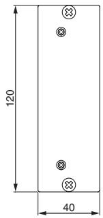
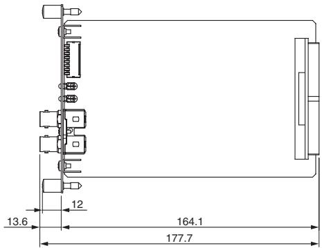
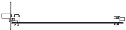
natural_image
Pure mechanical diagram showing a shaft and two blocks with no text or symbolsUnit: mm
* Specifications and descriptions in this owner's manual are for information purposes only. Yamaha Corp. reserves the right to change or modify products or specifications at any time without prior notice. Since specifications, equipment or options may not be the same in every locale, please check with your Yamaha dealer.
* Die technischen Daten und Beschreibungen in dieser Bedienungsanleitung dienen nur der Information. Yamaha Corp. behält sich das Recht vor, Produkte oder deren technische Daten jederzeit ohne vorherige Ankündigung zu verändern oder zu modifizieren. Da die technischen Daten, das Gerät selbst oder Sonderzubehör nicht in jedem Land gleich sind, setzen Sie sich im Zweifel bitte mit Ihrem Yamaha-Händler in Verbindung.
* Les caractéristiques techniques et les descriptions du mode d'emploi ne sont données que pour information. Yamaha Corp. se réserve le droit de changer ou modifier les produits et leurs caractéristiques techniques à tout moment sans aucun avis. Du fait que les caractéristiques techniques, les équipements et les options peuvent différer d'un pays à l'autre, adressez-vous au distributeur Yamaha le plus proche.
* Las especificaciones y descripciones de este manual del propietario tienen sólo el propósito de servir como información. Yamaha Corp. se reserva el derecho a efectuar cambios o modificaciones en los productos o especificaciones en cualquier momento sin previo aviso. Puesto que las especificaciones, equipos u opciones pueden no ser las mismas en todos los mercados, solicite información a su distribuidor Yamaha.
* Le specifiche e le descrizioni presenti in questo manuale sono fornite a fini puramente informativi. Yamaha Corp. si riserva il diritto di modificare prodotti o specifiche in qualsiasi momento senza preavviso. Dato che le specifiche, le apparecchiature o le opzioni possono essere diverse da paese a paese, verificarle con il proprio rappresentante Yamaha.
* Технические характеристики и их описания в данном руководстве пользователя предназначены только для общего сведения. Корпорация Yamaha сохраняет за собой право модифицировать свои изделия и менять их технические характеристики без предварительного уведомления. Поскольку технические характеристики, оборудование и набор возможностей могут зависеть от региона, обращайтесь за информацией к местному представителю корпорации Yamaha.
* 本使用说明书中的技术规格及介绍仅供参考。YAMAHA公司保留随时更改或修订产品或技术规格的权利,若确有更改,恕不事先通知。技术规格、设备或选购件在各个地区可能均会有所不同,因此如有问题,请和当地YAMAHA经销商确认。
* 仕様および外観は改良のため、予告なく変更することがあります。
Memo
For details of products, please contact your nearest Yamaha representative or the authorized distributor listed below.
NORTH AMERICA
CANADA
Yamaha Canada Music Ltd.
135 Milner Avenue, Scarborough, Ontario,
M1S 3R1, Canada
Tel: 416-298-1311
U.S.A.
Yamaha Corporation of America
6600 Orangethorpe Ave., Buena Park, Calif. 90620,
U.S.A.
Tel: 714-522-9011
CENTRAL & SOUTH AMERICA
MEXICO
PANAMA AND OTHER LATIN
AMERICAN COUNTRIES/
CARIBBEAN COUNTRIES
Yamaha Music Latin America, S.A.
Sherbourne Drive, Tilbrook, Milton Keynes,
MK7 8BL, England
Tel: 01908-366700
GERMANY
Yamaha Music Central Europe GmbH
Siemensstraße 22-34, 25462 Rellingen, Germany
Tel: 04101-3030
Yamaha Music Central Europe GmbH, Branch Switzerland
Seefeldstrasse 94, 8008 Zürich, Switzerland
Tel: 01-383 3990
AUSTRIA
Yamaha Music Central Europe GmbH, Branch Austria
Schleiergasse 20, A-1100 Wien, Austria
Tel: 01-60203900
CZECH REPUBLIC/SLOVAKIA/
HUNGARY/SLOVENIA
Yamaha Music Central Europe GmbH, Branch Austria, CEE Department
Schleiergasse 20, A-1100 Wien, Austria
Tel: 01-602039025
POLAND
Yamaha Music Central Europe GmbH
YS Copenhagen Liaison Office
Generatorvej 6A, DK-2730 Herlev, Denmark
Tel: 44 92 49 00
NORWAY
Yamaha Music (Russia)
Office 4015, entrance 2, 21/5 Kuznetskii
Most street, Moscow, 107996, Russia
Tel: 495 626 0660
OTHER EUROPEAN COUNTRIES
Yamaha Music Central Europe GmbH
Siemensstraße 22-34, 25462 Rellingen, Germany
Tel: +49-4101-3030
AFRICA
Yamaha Corporation,
Asia-Pacific Music Marketing Group
Nakazawa-cho 10-1, Naka-ku, Hamamatsu,
Japan 430-8650
Tel: +81-53-460-2313
MIDDLE EAST
TURKEY/CYPRUS
Yamaha Music Central Europe GmbH
Siemensstraße 22-34, 25462 Rellingen, Germany
Tel: 04101-3030
OTHER COUNTRIES
Yamaha Music Gulf FZE
LOB 16-513, P.O.Box 17328, Jubel Ali,
Dubai, United Arab Emirates
Tel: +971-4-881-5868
ASIA
THE PEOPLE'S REPUBLIC OF CHINA
Yamaha Music & Electronics (China) Co.,Ltd.
2F, Yunhedasha, 1818 Xinzha-lu, Jingan-qu, Shang-
hai, China
Tel: 021-6247-2211
INDIA
Yamaha Music India Pvt. Ltd.
5F Ambience Corporate Tower Ambience Mall Complex
Ambience Island, NH-8, Gurgaon-122001, Haryana,
India
Tel: 0124-466-5551
INDONESIA
PT. Yamaha Music Indonesia (Distributor)
PT. Nusantik
Gedung Yamaha Music Center, Jalan Jend. Gatot
Subroto Kav. 4, Jakarta 12930, Indonesia
Tel: 21-520-2577
KOREA
Yamaha Music Korea Ltd.
8F, 9F, Dongsung Bldg. 158-9 Samsung-Dong,
Kangnam-Gu, Seoul, Korea
Tel: 080-004-0022
MALAYSIA
Yamaha Music Malaysia, Sdn., Bhd.
Lot 8, Jalan Perbandaran, 47301 Kelana Jaya,
Petaling Jaya, Selangor, Malaysia
Tel: 3-78030900
SINGAPORE
Yamaha Music Asia Pte., Ltd.
03-11 A-Z Building
140 Paya Lebor Road, Singapore 409015
Tel: 747-4374
TAIWAN
Yamaha KHS Music Co., Ltd.
3F, #6, Sec.2, Nan Jing E. Rd. Taipei.
Taiwan 104, R.O.C.
Tel: 02-2511-8688
THAILAND
Siam Music Yamaha Co., Ltd.
4, 6, 15 and 16^th floor, Siam Motors Building,
891/1 Rama 1 Road, Wangmai,
Pathumwan, Bangkok 10330, Thailand
Tel: 02-215-2626
OTHER ASIAN COUNTRIES
Yamaha Corporation,
Asia-Pacific Music Marketing Group
Nakazawa-cho 10-1, Naka-ku, Hamamatsu,
Japan 430-8650
Tel: +81-53-460-2317
OCEANIA
AUSTRALIA
Yamaha Music Australia Pty. Ltd.
Level 1, 99 Queensbridge Street, Southbank,
Victoria 3006, Australia
Tel: 3-9693-5111
COUNTRIES AND TRUST
TERRITORIES IN PACIFIC OCEAN
Yamaha Corporation,
Asia-Pacific Music Marketing Group
Nakazawa-cho 10-1, Naka-ku, Hamamatsu,
Japan 430-8650
Tel: +81-53-460-2313

YAMAHA
Yamaha Pro Audio global website http://www.yamahaproaudio.com/ Yamaha Manual Library http://www.yamaha.co.jp/manual/
- HD-SDI DEMULTIPLEXER CARD MY8-SDI-D
- CANADA
- PRECAUTIONS
- PLEASE READ CAREFULLY BEFORE PROCEEDING
- WARNING
- CAUTION
- Information for Users on Collection and Disposal of Old Equipment
- [For business users in the European Union]
- [Information on Disposal in other Countries outside the European Union]
- Introduction
- About the host devices in which the MY8-SDI-D can be installed
- Installation information
- Accessories
- Part Names and Functions
- Panel
- ① GROUP SELECT Switches (SW1-4)
- Note:
- ② SYNC Switch (SW5)
- ③ MUTE Switch (SW6)
- ④ ERROR FILTER Switch (SW7)
- ⑤ ERROR FILTER Switch (SW8)
- ⑥ STATUS LED
- ⑦ HD-SDI INPUT Connector
- ⑧ HD-SDI THRU Connector
- ■ Dip Switches (SW2)
- ① Emu Switch
- ② Native Switch
- About the Word Clock Settings
- Appendix
- Specifications
- ■ Block Diagram
- Dimensions
- Memo
- NORTH AMERICA
- U.S.A.
- CENTRAL & SOUTH AMERICA
- MEXICO
- PANAMA AND OTHER LATIN
- AMERICAN COUNTRIES/
- CARIBBEAN COUNTRIES
- GERMANY
- AUSTRIA
- CZECH REPUBLIC/SLOVAKIA/
- HUNGARY/SLOVENIA
- POLAND
- NORWAY
- OTHER EUROPEAN COUNTRIES
- AFRICA
- MIDDLE EAST
- TURKEY/CYPRUS
- OTHER COUNTRIES
- ASIA
- THE PEOPLE'S REPUBLIC OF CHINA
- INDIA
- INDONESIA
- KOREA
- MALAYSIA
- SINGAPORE
- 03-11 A-Z Building
- TAIWAN
- THAILAND
- OTHER ASIAN COUNTRIES
- OCEANIA
- AUSTRALIA
- COUNTRIES AND TRUST
- TERRITORIES IN PACIFIC OCEAN
- YAMAHA
Brand : YAMAHA
Model : MY8-SDI-D
Category : Audio/Video Interface Card