DS-2CE56C2N-IT3 - Security Camera Hikvision - Free user manual and instructions
Find the device manual for free DS-2CE56C2N-IT3 Hikvision in PDF.

User questions about DS-2CE56C2N-IT3 Hikvision
0 question about this device. Answer the ones you know or ask your own.
Ask a new question about this device
Download the instructions for your Security Camera in PDF format for free! Find your manual DS-2CE56C2N-IT3 - Hikvision and take your electronic device back in hand. On this page are published all the documents necessary for the use of your device. DS-2CE56C2N-IT3 by Hikvision.
USER MANUAL DS-2CE56C2N-IT3 Hikvision
natural_image
Abstract grayscale circular design with concentric rings and a central eye-like shape (no text or symbols)HIKVISION
Dome Camera
User Manual
UD.6L0201D0172A01
www.hikvision.com
Thank you for purchasing our product. If there are any questions, or requests, please do not hesitate to contact the dealer.
This manual applies to
| Type | Model |
| I | DS-2CE5582P(N), DS-2CE55C2P(N) |
| II | DS-2CE5582P(N)-IR,DS-2CE55C2P(N)-IRD5-2CE5582P(N)-IRP, DS-2CE55C2P(N)-IRP |
| III | DS-2CE5682P(N)-IT3, DS-2CE56C2P(N)-IT3 |
| IV | DS-2CE5582P(N)-VFIR3 |
This manual may contain several technical incorrect places or printing errors, and the content is subject to change without notice.
The updates will be added to the new version of this manual. We will readily improve or update the products or procedures described in the manual.
DISCLAIMER STATEMENT
Underwriters Laboratories Inc. ("UL") has not tested the performance or reliability of the security or signaling aspects of this product. 0100001030115
UL has only tested for fire, shock or casualty hazards as outlined in UI's Standard(s) for Safety, UL60950-1.
UL Certification does not cover the performance or reliability of the security or signaling aspects of this product UL MAKES NO REPRESENTATIONS, WARRANTIES OR
CERTIFICATIONS WHATSOEVER REGARDING THE PERFORMANCE OR RELIABILITY OF ANY SECURITY OR SIGNALING RELATED FUNCTIONS OF THIS PRODUCT.
Regulatory Information
FCC Information
FCC compliance: This equipment has been tested and found to comply with the limits for a digital device, pursuant to part 15 of the FCC Rules. These limits are designed to provide reasonable protection against harmful interference when the equipment is operated in a commercial environment. This equipment generates, uses, and can radiate radio frequency energy and, if not installed and used in accordance with the instruction manual, may cause harmful interference to radio communications. Operation of this equipment in a residential area is likely to cause harmful interference in which case the user will be required to correct the interference at his own expense.
FCC Conditions
This device complies with part 15 of the FCC Rules. Operation is subject to the following two conditions:
- This device may not cause harmful interference.
- This device must accept any interference received, including interference that may cause undesired operation.
EU Conformity Statement

This product and - if applicable - the supplied accessories too are marked with "CE" and comply
therefore with the applicable harmonized European standards listed under the Low Voltage Directive 2006/95/EC, the EMC Directive 2004/108/EC.

2002/96/EC (WEEE directive): Products marked with this symbol cannot be disposed of as unsorted municipal waste in the European Union. For proper recycling, return this product to your local supplier
upon the purchase of equivalent new equipment, or dispose of it at designated collection points. For more information see:
www.recyclethis.info.

2006/66/EC (battery directive): This product contains a battery that cannot be disposed of as unsorted municipal waste in the European Union.
See the product documentation for specific battery information. The battery is marked with this symbol, which may include lettering to indicate cadmium (Cd), lead (Pb), or mercury (Hg). For proper recycling, return the battery to your supplier or to a designated collection point. For more information see: www.recyclethis.info.
1 Introduction
1.1 Product Features
This series of camera adopts new generation sensor with high sensitivity and advanced circuit design technology. It features high resolution, low image distortion and low noise etc., which makes it suitable for surveillance system and image processing system.
• High performance sensor and high resolution bring high-quality image
●IR LED enables day/night surveillance
•Day/night auto switch
•ATW brings high color rendition
●Auto electronic shutter control to adapt to the different surveillance environments
●Auto gain control, adaptive brightness
●High SNR brings high-quality image
•Ingress protection: IP66
Notes:
Type I camera doesn't support day/night auto switch and 38.
DS-2CE5582P N)RP and2DS-CE55C)P N IRP don't support IP66.
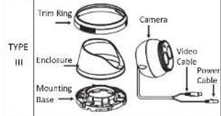
1.2 Overview
| TYPE I | Black Liner Adjustable ScrewLower DomePower CableCameraVideo Cable |
| TYPE II | Enclosure CameraTrim Ring Video CableMounting Base Power Cable |
 | |
| TYPE IV | Enclosure Camera Zoom & FocusMounting Base Power Cable Video CableCable |
2 Installation
Before you start:
- Please make sure that the device in the package is in good condition and all the assembly parts are included.
- Please make sure that all the related equipment is power-off during the installation.
- Check the specification of the products for the installation environment.
- Check whether the power supply is matched with your AC outlet to avoid damage.
- If the product does not function properly, please contact your dealer or the nearest service center. Do not disassemble the camera for repair or maintenance by yourself.
- Please make sure that the wall or the ceiling is strong enough to withstand 3 times the weight of the camera.
2.1 Ceiling Mounting for Type I Camera
Steps:
- Hold the mounting base, and rotate the lower dome counterclockwise to disassemble the lower dome and the black liner.
- Drill the screw holes and the cable hole then ceiling according to the supplied drill template.
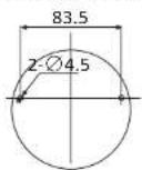
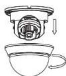
Figure 2-1 The Disassembling
- Route the cables to the cable hole and connect the corresponding power cable and video cable.
- Secure the mounting base to the ceiling with the self tapping screws.
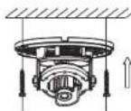
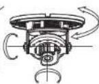
Figure 2-2 The Securing & 3-axis Adjustment
- Adjust the Lens
1). Loosen the tilting lock screws besides the lens.
2). Adjust the camera from the pan angle (0degrees); tilt angle (0\~90 degrees), and rotate the lens (0\~355 degrees) to get the optimum angle.
3). Tighten the tilting lock screws.
6.Fit the black liner back to the camera.
7. Install the lower dome back to the camera and rotate it clockwise to get it secured.
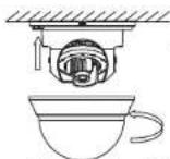
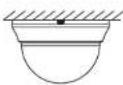
Figure 2-3 Complete the Installation
2.2 Ceiling Mounting for Type II/ III Camera
Steps:
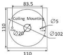
- Drill the screw holes and the cable hole according to the drill template.
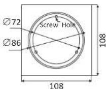
Figure 2-4 Drill Template of Type II Camera
text_image
83.5 Ceiling Mounting Ø5 Ø20 Ø102 110 110Figure 2-5 Drill Template of Type III Camera
- Secure the mounting base to the ceiling with the screws.
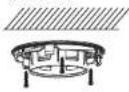
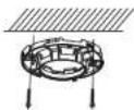
Figure 2-6 Secure the Mounting Base
- Route the cables to the cable hole and otherwise corresponding power cable and video cable.
- Secure the camera to the mounting base.
- Install the enclosure and the trim ring to camera.
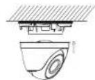
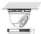
Figure 2-7 Secure the Components
- Adjust the surveillance angle according to the figure below.
- Rotate the trim ring clockwise to secure the camera.
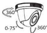
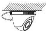
Figure 2-8 Lens Adjustment
2.3 Ceiling Mounting for Type IV Camera
Steps:
- Drill the screws holes and the cable hole on the ceiling according to the supplied drill template.
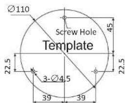
text_image
Ø110 Screw Hole Template 22.5 3-Ø4.5 39 39 45 22.5Figure 2-9 The Drill Template
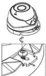
Figure 2-10 The Lock Screw
- Loosen the lock screw to disassemble the camera from the mounting base.
-
Secure the mounting base to the ceiling.
-
Route the cables to the cable hole and connect the corresponding cables.
- Secure the camera to the mounting base by tightening the lock screw.
- Adjust the camera according to the figure below to get an optimum angle.
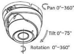
text_image
Pan 0°-360° Tilt 0°-75° Rotation 0°-360°Figure 2-11 Lens Adjustment
- Use the screwdriver to adjust the ZOOM screw and the FOCUS screw until you get the optimum image.
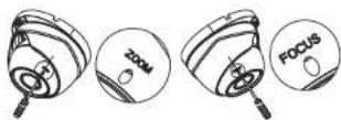
Figure 2-12 Zoom and Focus Adjustment
2.4 Power Supply
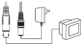
natural_image
Pure electrical circuit lines without any symbolsFigure 2-13 The Power Cable & the Video Cable
Note:
Please make sure that the power adapter is compatible with the camera, and the standard power supply is 12V DC. Please refer to the technical specification for more information.