TS118SU - Flat Screen Mount Chief - Free user manual and instructions
Find the device manual for free TS118SU Chief in PDF.


| Product Type | Flat Panel Wall Mount (Swing Arm) |
| Brand | Chief |
| Model | TS118SU |
| Weight Capacity | 35 lbs (15.9 kg) |
| VESA Compatibility | 75x75, 100x100, 200x100, 200x200 mm |
| Material | Steel |
| Color | Black |
| Mounting Type | Wall mount (wood stud or concrete/brick) |
| Tilt Adjustment | Yes (friction screws on both sides) |
| Swivel / Rotation | Yes (articulating arm) |
| Extension (Depth) | Not specified |
| Cable Management | Yes (integrated covers on upper and lower arms) |
| Wall Cover Included | Yes (plastic cover, fragile) |
| Installation Requirements | Wood stud (2x4, 16" center) or concrete/brick wall (8" min thickness) |
| Drywall Thickness Limit | Max 5/8" for wood stud installation |
| Included Hardware | Screws (M4, M5, M6), washers, spacers, lag bolts, concrete anchors |
| Tools Required | Phillips screwdriver, open-ended wrench, hex key (3/16"), drill, stud finder, level |
| Cleaning Instructions | Wipe with a soft, dry cloth; no harsh chemicals |
| Safety Certification | UL-listed (assumed) |
Frequently Asked Questions - TS118SU Chief
User questions about TS118SU Chief
0 question about this device. Answer the ones you know or ask your own.
Ask a new question about this device
Download the instructions for your Flat Screen Mount in PDF format for free! Find your manual TS118SU - Chief and take your electronic device back in hand. On this page are published all the documents necessary for the use of your device. TS118SU by Chief.
USER MANUAL TS118SU Chief
INSTALLATION INSTRUCTIONS
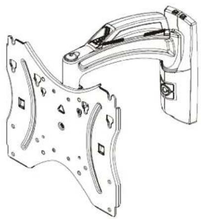
natural_image
Technical line drawing of a mechanical component with mounting holes and internal features (no text or symbols)TS110SU
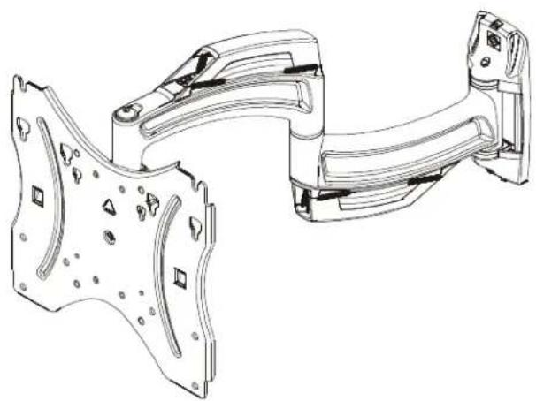
natural_image
Technical line drawing of a mechanical assembly with mounting brackets and mounting holes (no text or symbols)TS118SU
Small Thinstall™ Swing Arm
DISCLAIMER
Milestone AV Technologies and its affiliated corporations and subsidiaries (collectively "Milestone"), intend to make this manual accurate and complete. However, Milestone makes no claim that the information contained herein covers all details, conditions or variations, nor does it provide for every possible contingency in connection with the installation or use of this product. The information contained in this document is subject to change without notice or obligation of any kind. Milestone makes no representation of warranty, expressed or implied, regarding the information contained herein. Milestone assumes no responsibility for accuracy, completeness or sufficiency of the information contained in this document.
Chief® and Thinstall™ are registered trademarks of Milestone AV Technologies. All rights reserved.

IMPORTANT WARNINGS AND TIONS!

SAVE THESE INSTRUCTIONS!

WARNING: A WARNING alerts you to the possibility of serious injury or death if you do not follow the instructions.

CAUTION: A CAUTION alerts you to the possibility of damage or destruction of equipment if you do not follow the corresponding instructions.

WARNING: Use this mounting system only for its intended use as described in these instructions. Do not use attachments not recommended by the manufacturer.

WARNING: Never operate this mounting system if it is damaged. Return the mounting system to a service center for examination and repair.

WARNING: Do not use this product outdoors.

WARNING: Failure to read, thoroughly understand, and follow all instructions can result in serious personal injury, damage to equipment, or voiding of factory warranty! It is the installer's responsibility to make sure all components are properly assembled and installed using the instructions provided.

WARNING: Failure to provide adequate structural strength for this component can result in serious personal injury or damage to equipment! It is the installer's responsibility to make sure the structure to which this component is attached can support five times the combined weight of all equipment. Reinforce the structure as required before installing the component. The wall to which the mount is being attached may have a maximum drywall thickness of 5/8" (1.6cm) if it is being installed to wood studs. Do NOT install to a concrete wall of any kind that has a drywall covering!

WARNING: Exceeding the weight capacity can result in serious personal injury or damage to equipment! It is the installer's responsibility to make sure the combined weight of all components attached does not exceed 35 lbs (15.9 kg). Use with products heavier than the maximum weight indicated may result in collapse of the mount and its accessories causing possible injury.
IMPORTANT ! : The TS110SU/TS118SU mounts are designed to be mounted to an 8" concrete, 8"x8"x16" concrete block, clay brick or 2" x 4" wood studs (16" on center).
DIMENSIONS - TS110SU
![9.09 [230.9] 2.58 [65.5] 90° PAN LEFT/RIGHT" .08 [2] FACEPLATE THICKNESS 9.51 [241.6] 9.85 [250.1] MAXIMUM EXTENSION FROM WALL 12.0° MAX TILT MINIMUM DISTANCE FROM WALL 5.13 [130.3] 8.55 [217.3] 4.19 [106.3] 7.37 [187.1] COMPATIBLE MOUNTING PATTERNS INCLUDE: 75 X 75. 100 X 100. 200 X 100. 200 X 200 2.62 [66.5] SCREEN CENTER TO TOP LAG BOLT 6.24 [158.6] Ø .27 [6.7]](/content/2026/06/1148310/images/e31564182e186d105c8c39e4914e7eedb31c4717916dc9a0afb2049d737a8483.jpg)
DIMENSIONS - TS118SU
![9.09 [230.9] Ø1.06 [26.9] 2.49 [63.2] 90° PAN LEFT/RIGHT .08 [2] FACEPLATE THICKNESS 8.76 [222.4] 5.14 [130.50] 8.55 [217.3] 6.43 [163.3] 12.0° MAX TILT 18.01 [457.5] MAX EXTENSION FROM WALL 1.50 [38] MIN. DISTANCE FROM WALL 6.05 [153.7] COMPATIBLE MOUNTING PATTERNS INCLUDE: 75 X 75, 100 X 100, 200 X 100, 200 X 200 1.00 [25.4] SCREEN CENTER TO TOP LAG BOLT Ø27 [6.73]](/content/2026/06/1148310/images/c11e72a017024bdf819b294e1a831ef38d424f9a561c01b7d80a605e2dcd5db8.jpg)
LEGEND
 | Tighten Fastener |  | Pencil Mark |
| Apretar elemento de fijación | Marcar con lápiz | ||
| Befestigungsteil festziehen | Stiftmarkierung | ||
| Apertar fixador | Marcar com lápis | ||
| Serrare il fissaggio | Segno a matita | ||
| Bevestiging vastdraaien | Potloodmerkteken | ||
| Serrez les fixations | Marquage au crayon | ||
 | Loosen Fastener |  | Drill Hole |
| Aflojar elemento de fijación | Perforar | ||
| Befestigungsteil lösen | Bohrloch | ||
| Desapertar fixador | Fazer furo | ||
| Allentare il fissaggio | Praticare un foro | ||
| Bevestiging losdraaien | Gat boren | ||
| Desserrez les fixations | Percez un trou | ||
 | Phillips Screwdriver |  | Adjust |
| Destornillador Phillips | Ajustar | ||
| Kreuzschlitzschraubendreher | Einstellen | ||
| Chave de fendas Phillips | Ajustar | ||
| Cacciavite a stella | Regolare | ||
| Kruiskopschroevendraaier | Afstellen | ||
| Tournevis à pointe cruciforme | Ajuster | ||
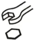 | Open-Ended Wrench |  | Remove |
| Llave de boca | Quitar | ||
| Gabelschlüssel | Entfernen | ||
| Chave de bocas | Remover | ||
| Chiave a punte aperte | Rimuovere | ||
| Steeksleutel | Verwijderen | ||
| Clé à fourche | Retirez | ||
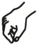 | By Hand |  | Optional |
| A mano | Opcional | ||
| Von Hand | Optional | ||
| Com a mão | Opcional | ||
| A mano | Opzionale | ||
| Met de hand | Optie | ||
| À la main | En option | ||
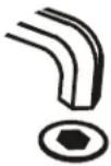 | Hex-Head Wrench | 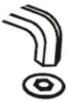 | Security Wrench |
| Llave de cabeza hexagonal | Llave de seguridad | ||
| Sechskantschlüssel | Sicherheitsschlüssel | ||
| Chave de cabeça sextavada | Chave de segurança | ||
| Chiave esagonale | Chiave di sicurezza | ||
| Zeskantsleutel | Veiligheidssleutel | ||
| Clé à tête hexagonale | Clé de sécurité |
TOOLS REQUIRED FOR INSTALLATION
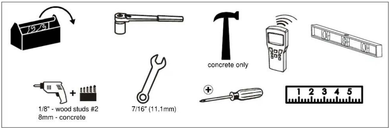
PARTS
!["A" A1 (4) M4x12mm A2 (4) M4x16mm A3 (4) M4x25mm "B" B1 (4) M5x12mm B2 (4) M5x16mm B3 (4) M5x25mm "C" C1 (4) M6x12mm C2 (4) M6x16mm C3 (4) M6x25mm "D" D1 (4) M4 D2 (4) M5 D3 (8) 1/4" E (2) 1/4 x 2 1/2" F (2) [concrete anchor] G (1) 3/16" TS118SU H (1) [main assembly] J (1) [wall cover] TS110SU H (1) [main assembly] J (1) [wall cover]](/content/2026/06/1148310/images/86ccc6bbe8b4ef8f630afbe22360add41a2b6d490c3fde1466ab14941e64982a.jpg)
Assembly And Installation
Install to Wall
Install Main Assembly to Wall - Wood Studs

WARNING: Failure to provide adequate structural strength for this component can result in serious personal injury or damage to equipment! It is the installer's responsibility to make sure the structure to which this component is attached can support five times the combined weight of all equipment. Reinforce the structure as required before installing the component. The wall to which the mount is being attached may have a maximum drywall thickness of 5/8" (1.6cm).
- Determine mounting location using a stud finder to locate a wood stud.
- Measure 2 5/8" above desired center line if mounting TS110SU or 1" below desired center line if mounting TS118SU and mark a hole at this location. (See Figure 1)
IMPORTANT ! : Use a level to make sure main assembly (H) is level when mounted to the wall!
IMPORTANT ! : The TS110SU/TS118SU mounts are designed to be mounted to a 2" x 4" wood studs (16" on center) wall.
3. Drill one 1/8" hole at location marked in Step 2. (See Figure 1)
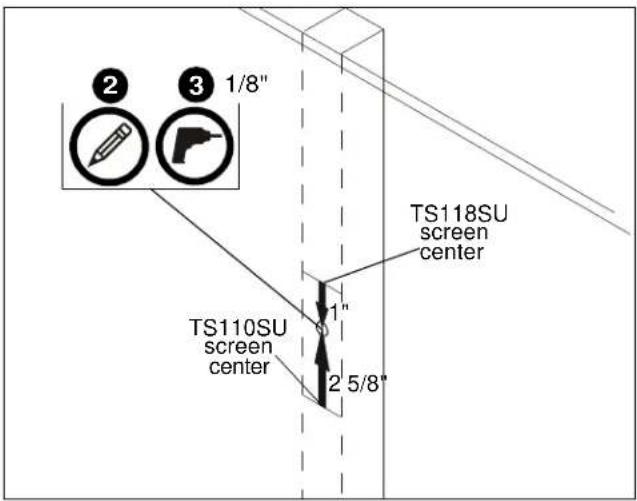
Figure 1
- Install one 1/4 x 2 1/2" lag bolt (E) into hole, leaving screw hanging out 1/2" from the wall. (See Figure 2)
- Hang main assembly (H) onto lag bolt (E) by latching key-shaped hole over top of bolt. (See Figure 2)
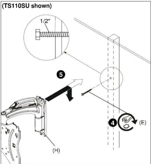
Figure 2
- Mark holes at lower mounting hole location. (See Figure 3)
- Remove main assembly (H) from wall.
- Drill 1/8" hole at location marked in Step 6. (See Figure 3)
- Hang main assembly (H) back onto wall.
- Install remaining 1/4 x 2 1/2" lag bolt (E) into hole drilled in Step 8 to secure mount to wall. (See Figure 3)
- Tighten both lag bolts (E) to fully secure mount to wall.
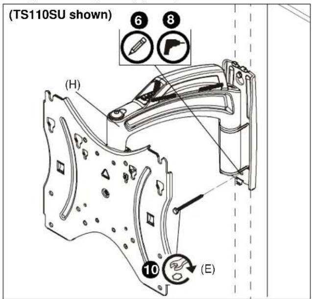
Figure 3
- Proceed ahead to Display Installation Section on page 8.
Install Main Assembly to Wall - Hollow Concrete Block, Poured Concrete or Clay Brick

WARNING: Failure to provide adequate structural strength for this component can result in serious personal injury or damage to equipment! It is the installer's responsibility to make sure the structure to which this component is attached can support five times the combined weight of all equipment. Reinforce the structure as required before installing the component. Do NOT install to a concrete wall of any kind that has a drywall covering!

WARNING: INSTALLING THE TS110SU/TS118SU INTO UNDERRATED OR DAMAGED CONCRETE CAN LEAD TO SERIOUS INJURY OR DAMAGE TO PRODUCT! Never install the TS110SU/TS118SU into cracked, chipped or flaking concrete.
- Determine mounting location.
- Measure 2 5/8" above desired center line if mounting TS110SU or 1" below desired center line if mounting TS118SU and mark a hole at desired mounting location. (See Figure 4)
IMPORTANT ! : Use a level to make sure main assembly (H) is level when mounted to the wall!
IMPORTANT ! : The TS110SU/TS118SU mounts are designed to be mounted to an 8" concrete, 8"x8"x16" concrete block or clay brick wall.
- Drill one 8mm hole at location marked in Step 2. (See Figure 4)
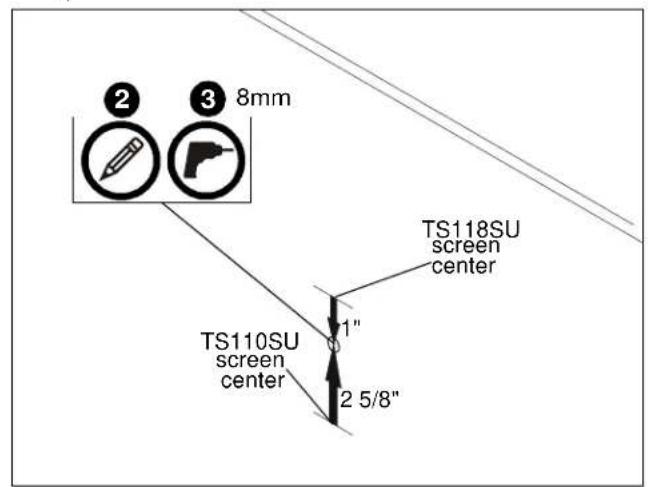
Figure 4
- Install one concrete anchor (F) into drilled hole. (See Figure 5)
- Install one 1/4 x 2 1/2" lag bolt (E) into concrete anchor (F), leaving bolt hanging out 1/2" from the wall. (See Figure 5)
- Hang main assembly (H) onto lag bolt (E) by latching key-shaped hole over top of bolt. (See Figure 5)
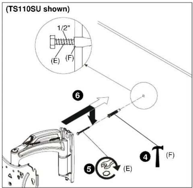
Figure 5
- Mark hole at lower mounting hole location. (See Figure 6)
- Remove main assembly (H) from wall.
- Drill 8mm hole at marked location. (See Figure 6)
- Install remaining concrete anchor (F) into drilled hole. (See Figure 6)
- Hang main assembly (H) back onto wall.
- Install remaining 1/4 x 2 1/2" lag bolt (E) into concrete anchor (F) to secure mount to wall. (See Figure 6)
- Tighten both lag bolts (E) to fully secure mount to wall.
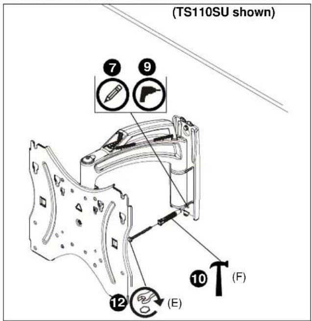
Figure 6
Display Installation

WARNING: Exceeding the weight capacity can result in serious personal injury or damage to equipment! It is the installer's responsibility to make sure the combined weight of all components attached does not exceed 35 lbs (15.9 kg). Use with products heavier than the maximum weight indicated may result in collapse of the mount and its accessories causing possible injury.

CAUTION: Using screws of improper diameter may damage your display! Proper screws will easily thread into display mounting holes.
NOTE: Compatible mounting patterns for the TS110SU and TS118SU include 75mm x 75mm, 100mm x 100mm, 200mm x 100mm and 200mm x 200mm.
- Select screw diameter by examining hardware (A-C) (4mm, 5mm or 6mm) and comparing with mounting holes on display.

CAUTION: Using screws of improper length may damage your display! Proper screws will have adequate thread engagement without contacting bottom of display mounting holes.
- Select screw length:
- Using your hand, insert SHORTEST length screw of selected diameter (A1, B1 or C1) into display mounting hole. Do NOT fully thread screw into hole at this time.
- Install two selected screws (A-C) into upper two holes on back of display. (See Figure 7)
IMPORTANT ! : If using M4 or M5 screws (A or B), washer hardware (D1 or D2) should be used to ensure tight fit into the faceplate holes!
IMPORTANT ! : For recessed mounting holes or to gain extra space, 1/4" spacers (D3) may be used in between the back of the display and the faceplate. Multiple spacers may be used on each screw if more space is needed.
- Hang display by two screws onto faceplate through either inner or outer teardrop mounting holes. (200x200 mounting pattern shown) (See Figure 8)
- Install two selected screws (A-C) through selected washer hardware (D1 or D2 if necessary), lower holes on faceplate and into lower two holes on display. (See Figure 8)
IMPORTANT ! : For recessed mounting holes or to gain extra space, 1/4" spacers (D3) may be used in between the back of the display and the faceplate. Multiple spacers may be used on each screw if additional space is required.
- Tighten all hardware to ensure display is securely mounted.
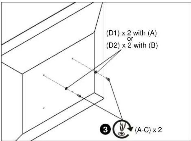
Figure 7
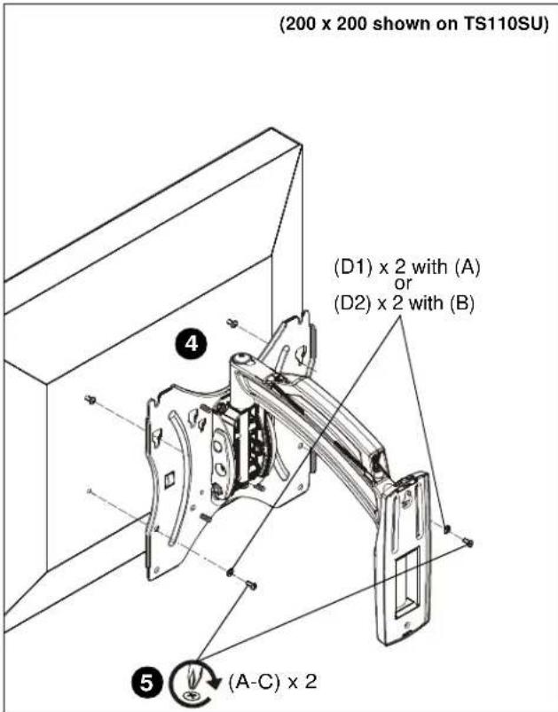
Figure 8
Wall Cover Installation

CAUTION: Wall covers are fragile and may be damaged or broken if installed with excessive force! Use caution when installing and removing wall covers.
- Pull apart top or bottom section of wall cover (J) so that it fits over the main assembly arm. For the TS110SU pull apart the top and for the TS118SU pull apart the bottom. (See Figure 9) or (See Figure 10)
- Install wall cover (J) onto main assembly making sure holes on cover latch over tabs on main assembly. (See Figure 9) or (See Figure 10)
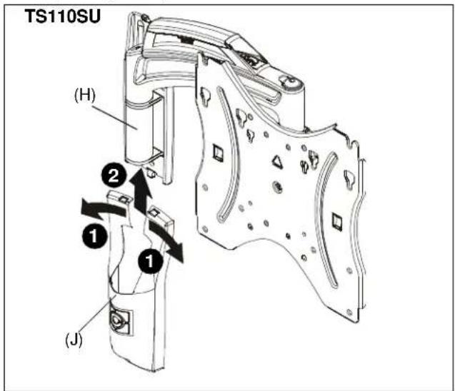
Figure 9
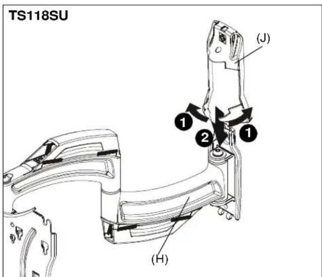
Figure 10
Cable Management
- Make all cable connections to display.
- Open cable management covers on upper and lower swing arms by unhinging center tabs and lifting covers to the open position. (See Figure 11)
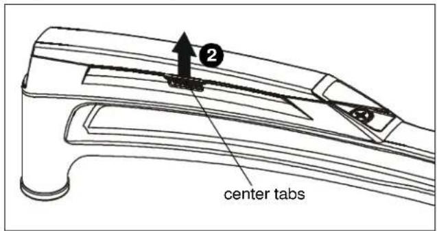
Figure 11
- Route cables on top of upper arm. (See Figure 12)
NOTE: Cable ties (not included) may be used to secure cables to back of faceplate using cable tie holes on either side of faceplate.
- (Optional) Use cable ties (not included) to secure cables to upper arms by threading ties around cable and through cable tie holes inside the covers. (See Figure 12)
- Close upper cable management cover. (See Figure 12)
- (TS118SU only) Route cables under lower portion of swing arm. (See Figure 12)
- (Optional for TS118SU only) Use cable ties (not included) to secure cables to lower arms by threading ties around cable and through cable tie holes inside the covers. (See Figure 12)
- (TS118SU only) Close lower cable management cover. (See Figure 12)
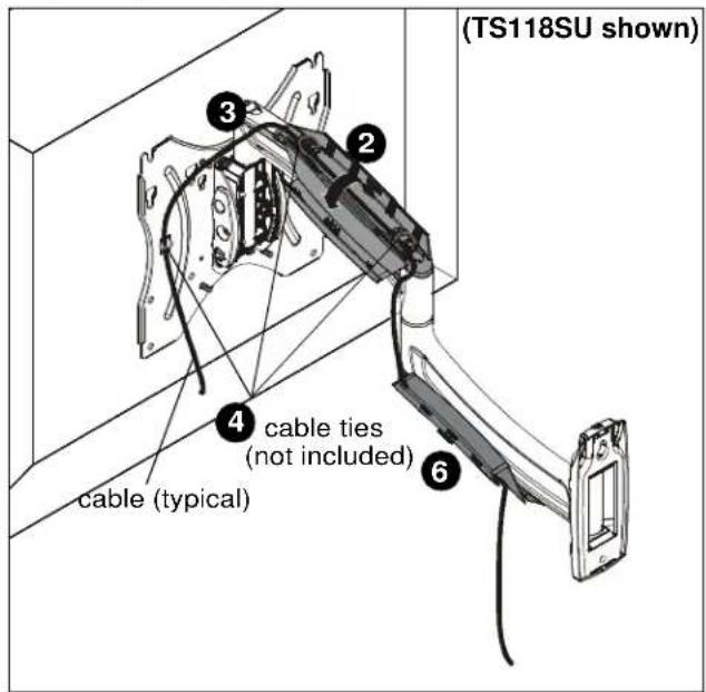
Figure 12
Tilt Friction Adjustment
- Adjust tilt friction adjustment screws to increase or decrease tilt friction. (See Figure 13)
NOTE: There is a tilt friction adjustment screw on each side of the pitch mechanism that must be adjusted evenly in order to properly adjust tension.
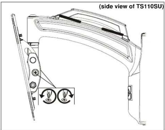
Figure 13
Arm Tension Adjustment
- Use 3/16" hex key (T) to adjust arm tension at any of the tension adjustment points. (See Figure 14) or (See Figure 15)
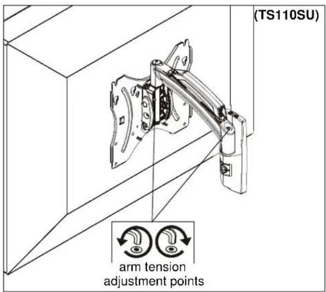
Figure 14
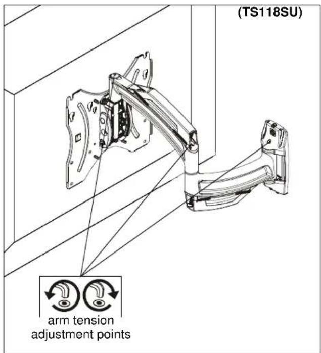
Figure 15
TS110SU/TS118SU
Installation Instructions
- INSTALLATION INSTRUCTIONS
- Small Thinstall™ Swing Arm
- DISCLAIMER
- IMPORTANT WARNINGS AND TIONS!
- SAVE THESE INSTRUCTIONS!
- Assembly And Installation
- Install to Wall
- Install Main Assembly to Wall - Wood Studs
- Install Main Assembly to Wall - Hollow Concrete Block, Poured Concrete or Clay Brick
- Display Installation
- Wall Cover Installation
- Cable Management
- Tilt Friction Adjustment
- Arm Tension Adjustment
Brand : Chief
Model : TS118SU
Category : Flat Screen Mount