AP21 - Access Point Mist - Free user manual and instructions
Find the device manual for free AP21 Mist in PDF.


| Product Type | Indoor Access Point |
| Model | AP21 |
| Brand | Mist |
| Dimensions (W x D x H) | 18.5 x 18.5 x 4.5 cm |
| Weight | 450 g |
| Power Supply | 802.3af PoE (Power over Ethernet) |
| Wi-Fi Standards | 802.11a/b/g/n/ac/ax (Wi-Fi 6) |
| MIMO Configuration | 2x2:2 |
| Max Data Rate | 1.2 Gbps (2.4 GHz) + 2.4 Gbps (5 GHz) |
| Ethernet Ports | 1 x 2.5 GbE (RJ-45) |
| Management | Cloud-managed via Mist portal |
| Antenna Type | Internal omnidirectional |
| Operating Temperature | 0°C to 40°C |
| Mounting | Ceiling or wall mount (bracket included) |
| Security Features | WPA3-Enterprise, AES encryption, rogue AP detection |
| Maintenance | Cloud firmware updates, minimal physical upkeep |
| Cleaning Instructions | Wipe with dry cloth; avoid liquids |
| Spare Parts Availability | Contact Mist support or authorized partners |
| Repairability | Not user-serviceable; professional repair recommended |
| Certifications | FCC, CE, IC, RoHS |
| Warranty | Limited lifetime warranty |
Frequently Asked Questions - AP21 Mist
User questions about AP21 Mist
0 question about this device. Answer the ones you know or ask your own.
Ask a new question about this device
Download the instructions for your Access Point in PDF format for free! Find your manual AP21 - Mist and take your electronic device back in hand. On this page are published all the documents necessary for the use of your device. AP21 by Mist.
USER MANUAL AP21 Mist
The Mist AP21 is a high value, Enterprise-grade Access Point for 802.11ac Wave 2 Gigabit WiFi Mobility & Assurance Services and Bluetooth Low Energy Location services for delivering BLE Engagement and Asset Visibility Services.
Understanding the Product
Included in the box:
- AP21
I/O ports and Kensington lock

| Reset Reset to the factory default settings | |
| 12VDC Support for the 12VDC power supply recommended by Mist | |
| Eth1+PoE Out | 10/100/1000 BaseT RJ45 interface that can output 48V PoE |
| Eth0+PoE In | 10/100/1000 BaseT RJ45 interface that supports 802.3at PoE PD |
AP21 Mounting
APBR-U Mounting box options
| Holes | Mounting options |
| 1 | US Single gang, 4 inch round, 3.5 inch round |
| 2 | US Double gang, Wall/ceiling mount |
| 3 | US 4 inch square |
| 4 | EU junction box |
In a wall mount installation, please use screws that have a 1/4in. (6.3mm) diameter head with a length at least 2 in. (50.8mm).
Mounting to a 9/16 inch or 15/16 inch T-bar
Step 1
Step 2

Step 3
Step 4

Step1.
Mount APBR-U to the t-bar
Step 2.
Rotate APBR-U to lock to the t-bar
Step 3.
Assemble 4 shoulder screws to the AP if they did not come pre-installed. Step 4.
Slide the AP with shoulder screws on the APBR-U until the lock is engaged
US single gang, 3.5 or 4 inch round junction box


Step 1
Mount APBR-U to the box using two screws and the #1 holes. Make sure Ethernet cable extends thru the bracket.
Step 2
Assemble 4 shoulder screws to the AP if they did not come pre-installed
Step 3
Slide the AP with shoulder screws on the APBR-U until the lock is engaged
Step 2
Step 3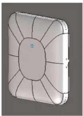
US double gang junction box

Step 2

Step 3

Step 1
Mount APBR-U to the box using two screws and the #2 holes. Make sure Ethernet cable extends thru the bracket.
Step 2
Assemble 4 shoulder screws to the AP if they did not come pre-installed
Step 3
Slide the AP with shoulder screws on the APBR-U until the lock is engaged
US 4 inch square junction box

Step 2

Step 3

Step 1
Mount APBR-U to the box using two screws and the #3 holes. Make sure Ethernet cable extends thru the bracket.
Step 2
Assemble 4 shoulder screws to the AP if they did not come pre-installed
Step 3
Slide the AP with shoulder screws on the APBR-U until the lock is engaged
EU junction box

Step 2
Step 3
Step 1
Mount APBR-U to the box using two screws and the #4 holes. Make sure Ethernet cable extends thru the bracket.
Step 2
Assemble 4 shoulder screws to the AP if they did not come pre-installed
Step 3
Slide the AP with shoulder screws on the APBR-U until the lock is engaged
Recessed 15/16 inch T-bar

Step 2

Step 1
Mount the APBR-ADP-RT15 to the t-bar
Step 2
Mount the APBR-U to the APBR-ADP-RT15. Rotate the APBR-U to lock to the APBR-ADP-RT15
Step 3
Assemble 4 shoulder screws to the AP if they did not come pre-installed
Step 4
Slide the AP with shoulder screws on the APBR-U until the lock is engaged
Step 3

Recessed 9/16 inch T-bar or channel rail
Step 1
Mount the APBR-ADP-CR9 to the t-bar
Step 2
Mount the APBR-U to the APBR-ADP-CR9. Rotate the APBR-U to lock to the APBR-ADP-CR9
Step 3
Assemble 4 shoulder screws to the AP if they did not come pre-installed
Step 4
Slide the AP with shoulder screws onto the APBR-U until the lock engages.
1.5 inch T-bar
Step 1
Mount the APBR-ADP-WS15 to the T-bar.
Step 2
Mount the APBR-U to the APBR-ADP-WS15. Rotate the APBR-U to lock it to the APBR-ADP-WS15.
Step 3
Assemble 4 shoulder screws to the AP if they did not come pre-installed.
Step 4
Slide the AP with shoulder screws onto the APBR-U until the lock engages.
Mounting to a 5/8 inch threaded rod. Step 1: Install the APBR-T58 bracket to the 5/8 inch threaded rod, securing it with the provided lock washer and nut. Step 2: Install the APBR-SW1 on the APBR-T58 with the provided screws. Step 3: Slide the AP onto the APBR-SW1 bracket to lock. The bracket attaches to a rod that is 5/8"-11.
Mounting to a 16mm threaded rod. Step 1
Step 1: Install the APBR-M16 bracket to the 16mm threaded rod, securing it with the provided lock washer and nut. Step 2: Install the APBR-SW1 on the APBR-M16 with the provided screws. Step 3: Slide the AP onto the APBR-SW1 bracket to lock.


The bracket attaches to a rod that is M16-2.
Technical Specifications:
| Feature Description | |
| Power options | 802.3af PoE12V / 3A DC power supply |
| Dimensions 203mm x 203mm x 40mm (7.99in x 7.99in x 1.57in) | |
| Weight 0.636 kg (1.4 lbs) | |
| Operating temperature | Internal antenna 0° to 40°C |
| Operating humidity | 10% to 90% maximum relative humidity, non-condensing |
| Operating altitude 3,048m (10,000 ft) | |
| I/O | 1 - 10/100/1000BASE-T auto-sensing RJ-45 with PoE In1 - 10/100/1000BASE-T auto-sensing RJ-45 with 48VdcPoE Out |
| RF | 2.4GHz - 2x2:2 spatial streams 802.11ac5GHz - 2x2:2 spatial streams 802.11ac2.4GHz BLE with Dynamic Antenna Array |
| Indicators Multi-color status LED | |
| Compliance standards | UL 60950-1CAN/CSA-C22.2 No. 60950-1UL 2043FCC Part 15.247, 15.407, 15.107, and 15.109FCC Part 15 Class BRSS-247ICES-003 (Canada) |
The unit and all interconnected equipment must be installed indoors within the same building, including all PoE-powered network connections as described by Environment A of the IEEE 802.3af standard.
Suitable for use in environmental air space in accordance with Section 300-22(C) of the National Electrical Code, and Sections 2-128, 12-010(3), and 12-100 of the Canadian Electrical Code, Part 1, CSA C22.1.
Warning: The AP must be mounted only horizontally if you mount it into a plenum space.
Warranty Information
The AP21 family of Access Points comes with a limited lifetime warranty.
Ordering Information:
Access Points
| AP21-US | WiFi & BLE Array AP with internal antennas for the US domain |
| AP21-WW | WiFi & BLE Array AP with internal antennas for the Worldwide domain |
Mounting brackets
| APBR-U Universal AP Bracket for T-Rail and Drywall mounting for Indoor Access Points | |
| AP41BR1 Premium AP T-bar ceiling mounting bracket kit | |
| APBR-T58 5/8-inch threaded rod bracket | |
| APBR-M16 16mm threaded rod bracket | |
| APBR-ADP-CR9 / AP41BR1-CR | Adapter for channel rail and recessed 9/16" t-rail |
| APBR-ADP-RT15 / AP41BR1-RT | Adapter for recessed 15/16" t-rail |
| APBR-ADP-WS15 Adapter for recessed 1.5" t-rail | |
| APBR-SW1 / BT11BR1 Drywall ceiling bracket for AP21/BT11 | |
Power Supply options
| 12V DC supply 100-24 | 0VAC, 50-60 Hz, inputAll regions (output): 12V/3A DC output |
This product is intended to be supplied by an UL Listed and/or IEC/EN60950-1 approved power adapter suitable for use at maximum ambient temperature 40 degrees C, whose output meets SELV and LPS, and is rated 12 Vdc / 3A with an altitude of operation up to 3048m
This product is intended to be supplied by an UL Listed and/or IEC/EN60950-1 approved PoE DC Power Injector suitable for use at maximum ambient temperature 40 degrees C, whose output meets SELV and LPS, rated 57 Vdc / 0.6A with an altitude of operation up to 3048m
If you need further assistance with purchasing the power source, please contact Mist Systems for further information.
Regulatory Compliance Information:
This product and all interconnected equipment must be installed indoors within the same building, including the associated LAN connections as defined by the 802.3at Standard.
FCC Requirement for Operation in the United States of America:
FCC Guideline for Human Exposure
This equipment complies with FCC radiation exposure limits set forth for an uncontrolled environment. This equipment should be installed and operated with minimum distance 20 cm between the radiator & your body.
This device complies with Part 15 of the FCC Rules. Operation is subject to the following two conditions: (1) This device may not cause harmful interference, and (2) this device must accept any interference received, including interference that may cause undesired operation.
This equipment has been tested and found to comply with the limits for a Class B digital device, pursuant to Part 15 of the FCC Rules. These limits are designed to provide reasonable protection against harmful interference in a residential installation. This equipment generates, uses and can radiate radio frequency energy and, if not installed and used in accordance with the instructions, may cause harmful interference to radio communications. However, there is no guarantee that interference will not occur in a particular installation. If this equipment does cause harmful interference to radio or television reception, which can be determined by turning the equipment off and on, the user is encouraged to try to correct the interference by one of the following measures:
- Reorient or relocate the receiving antenna.
- Increase the separation between the equipment and receiver.
- Connect the equipment into an outlet on a circuit different from that to which the receiver is connected.
- Consult the dealer or an experienced radio/TV technician for help.
FCC Caution
- Any changes or modifications not expressly approved by the party responsible for compliance could void the user's authority to operate this equipment.
- This transmitter must not be co-located or operating in conjunction with any other antenna or transmitter.
- Operations in the 5.15GHz – 5.25GHz band are restricted to indoor usage only.
FCC Note
- The country code selection is for non-US model only and is not available to all US models. Per FCC regulation, all WiFi products marketed in the US must be fixed to US operating channels only.
Industry Canada
This device complies with ISED's license-exempt RSS's. Operation is subject to the following two conditions: (1) This device may not cause harmful interference, and (2) this device must accept any interference received, including interference that may cause undesired operation.
- The device for operation in the band 5150-5250 MHz is only for indoor use to reduce the potential for harmful interference to co-channel mobile satellite systems;
- The maximum antenna gain permitted for devices in the band 5725-5850 MHz shall be such that the equipment still complies with the e.i.r.p. limits specified for point-to-point and non-point-to-point operation as appropriate; and
- Users should also be advised that high-power radars are allocated as primary users (i.e. priority users) of the bands 5650-5850 MHz and that these radars could cause interference and/or damage to LE-LAN devices.
Warning
Radiation Exposure Statement:
This equipment complies with ISED radiation exposure limits set forth for an uncontrolled environment. This equipment should be installed and operated with
minimum distance 20cm between the radiator & your body.


- UNDERSTANDING THE PRODUCT
- I/O PORTS AND KENSINGTON LOCK
- AP21 MOUNTING
- MOUNTING TO A 9/16 INCH OR 15/16 INCH T-BAR
- US SINGLE GANG, 3.5 OR 4 INCH ROUND JUNCTION BOX
- US DOUBLE GANG JUNCTION BOX
- STEP
- US 4 INCH SQUARE JUNCTION BOX
- WARRANTY INFORMATION
- ORDERING INFORMATION
- REGULATORY COMPLIANCE INFORMATION
- FCC REQUIREMENT FOR OPERATION IN THE UNITED STATES OF AMERICA
- FCC CAUTION
- FCC NOTE
- INDUSTRY CANADA
- WARNING
- RADIATION EXPOSURE STATEMENT
Brand : Mist
Model : AP21
Category : Access Point