
YSP-1000 - Soundbar YAMAHA - Free user manual and instructions
Find the device manual for free YSP-1000 YAMAHA in PDF.
| Product Type | Soundbar with digital sound projectors |
| Brand | Yamaha |
| Model | YSP-1000 |
| Dimensions (W x H x D) | 1030 x 86 x 110 mm |
| Weight | 7.2 kg |
| Power supply | 220-240 V AC, 50/60 Hz |
| Power consumption | 45 W (standby < 0.5 W) |
| Total output power | 120 W (6 x 20 W) |
| Audio technology | Digital sound projectors (DSP), Virtual Surround, Dolby Digital, DTS |
| Number of speakers | 21 speakers (19 tweeters + 2 subwoofers) |
| Inputs | 2x HDMI (ARC compatible), 1x optical, 1x coaxial, 1x stereo analog |
| Outputs | 1x HDMI (ARC), 1x wired subwoofer |
| Main functions | Virtual surround sound, listening modes (Cinema, Music, Game, etc.), automatic sound calibration (IntelliBeam), remote control included, OSD display |
| Maintenance and cleaning | Dust with a soft, dry cloth. Do not use abrasive products or solvents. |
| Safety | Do not open the device. Avoid heat sources and moisture. Use a grounded outlet. |
| Spare parts and repairability | Contact a Yamaha authorized service center for repairs. Parts available through a network of authorized dealers. |
| General information | Manual available in multiple languages. Keep this manual for future reference. Made in China. |
Frequently Asked Questions - YSP-1000 YAMAHA
User questions about YSP-1000 YAMAHA
0 question about this device. Answer the ones you know or ask your own.
Ask a new question about this device
Download the instructions for your Soundbar in PDF format for free! Find your manual YSP-1000 - YAMAHA and take your electronic device back in hand. On this page are published all the documents necessary for the use of your device. YSP-1000 by YAMAHA.
USER MANUAL YSP-1000 YAMAHA
CAUTION: READ THIS BEFORE OPERATING THIS UNIT.
1 To assure the finest performance, please read this manual carefully. Keep it in a safe place for future reference.
2 Install this sound system in a well ventilated, cool, dry, clean place with at least 5 cm of space above (or below) this unit – away from direct sunlight, heat sources, vibration, dust, moisture, and/or cold.
3 Locate this unit away from other electrical appliances, motors, or transformers to avoid humming sounds.
4 Do not expose this unit to sudden temperature changes from cold to hot, and do not locate this unit in an environment with high humidity (i.e. a room with a humidifier) to prevent condensation inside this unit, which may cause an electrical shock, fire, damage to this unit, and/or personal injury.
5 Avoid installing this unit where foreign object may fall onto this unit and/or this unit may be exposed to liquid dripping or splashing. On the top of this unit, do not place:
- Other components, as they may cause damage and/or discoloration on the surface of this unit.
- Burning objects (i.e. candles), as they may cause fire, damage to this unit, and/or personal injury.
- Containers with liquid in them, as they may fall and liquid may cause electrical shock to the user and/or damage to this unit.
6 Do not cover this unit with a newspaper, tablecloth, curtain, etc. in order not to obstruct heat radiation. If the temperature inside this unit rises, it may cause fire, damage to this unit, and/or personal injury.
7 Do not plug in this unit to a wall outlet until all connections are complete.
8 Do not operate this unit upside-down. It may overheat, possibly causing damage.
9 Do not use force on switches, knobs and/or cords.
10 When disconnecting the power supply cable from the wall outlet, grasp the plug; do not pull the cable.
11 Do not clean this unit with chemical solvents; this might damage the finish. Use a clean, dry cloth.
12 Only voltage specified on this unit must be used. Using this unit with a higher voltage than specified is dangerous and may cause fire, damage to this unit, and/or personal injury. YAMAHA will not be held responsible for any damage resulting from use of this unit with a voltage other than specified.
13 Do not attempt to modify or fix this unit. Contact qualified YAMAHA service personnel when any service is needed. The cabinet should never be opened for any reasons.
14 When not planning to use this unit for long periods of time (i.e. vacation), disconnect the AC power plug from the wall outlet.
15 Be sure to read the “TROUBLESHOOTING” section on common operating errors before concluding that this unit is faulty.
16 Before moving this unit, press STANDBY/ON to set this unit in standby mode, and disconnect the AC power plug from the wall outlet.
17 Condensation will form when the surrounding temperature changes suddenly. Disconnect the power supply cable from the outlet, then leave the unit alone.
18 When using the unit for a long time, the unit may become warm. Turn the power off, then leave the unit alone for cooling.
19 Install this unit near the wall outlet and where the AC power plug can be reached easily.
WARNING
TO REDUCE THE RISK OF FIRE OR ELECTRIC SHOCK, DO NOT EXPOSE THIS UNIT TO RAIN OR MOISTURE.
WARNING
THE POWER SUPPLY CABLE OF THIS UNIT MUST BE CONNECTED TO THE MAIN SOCKET OUTLET VIA A PROTECTIVE EARTHING CONNECTION.
This unit is not disconnected from the AC power source as long as it is connected to the AC wall outlet, even if this unit itself is turned off. This state is called the standby mode. In this state, this unit is designed to consume a very small quantity of power.
FOR U.K. CUSTOMERS
If the socket outlets in the home are not suitable for the plug supplied with this appliance, it should be cut off and an appropriate 3 pin plug fitted. For details, refer to the instructions described below. Note that the plug severed from the mains lead must be destroyed, as a plug with bared flexible cord is hazardous if engaged in a live socket outlet.
IMPORTANT
THE WIRES IN MAINS LEAD ARE COLOURED IN ACCORDANCE WITH THE FOLLOWING CODE:
Blue: NEUTRAL
Brown: LIVE
As the colours of the wires in the mains lead of this apparatus may not correspond with the coloured markings identifying the terminals in your plug, proceed as follows: The wire which is coloured BLUE must be connected to the terminal which is marked with the letter N or coloured BLACK. The wire which is coloured BROWN must be connected to the terminal which is marked with the letter L or coloured RED. Make sure that neither core is connected to the earth terminal of the three pin plug.
CAUTION
Danger of explosion if battery is incorrectly replaced. Replace only with the same or equivalent type.
CAUTION
Use of controls or adjustments or performance of procedures other than those specified herein may result in hazardous radiation exposure.
CONTENTS
INTRODUCTION
OVERVIEW 2
FEATURES....3
USING THIS MANUAL......4
SUPPLIED ACCESSORIES .... 5
CONTROLS AND FUNCTIONS ...... 6
Front panel....6
Front panel display 7
Rear panel 8
Remote control....9
PREPARATION
INSTALLATION 11
Before installing this unit.... 11
Installing this unit 11
CONNECTIONS 15
Connecting a TV....16
Connecting a DVD player/recorder.... 17
Connecting a VCR.... 18
Connecting a digital satellite tuner or a cable TV tuner....19
Connecting a digital airwave tuner....20
Connecting other external components ...... 21
Connecting a subwoofer 22
Affixing the optical cable 23
Connecting the power supply cable.... 23
About the RS-232C/REMOTE IN/ IR-OUT terminals.... 23
SETUP
GETTING STARTED....24
Installing batteries in the remote control 24
Operation range of the remote control....24
Using the remote control 25
Turning on the power....25
USING SET MENU....26
Displaying the OSD....26
The flow chart of SET MENU....27
AUTO SETUP....28
The flow chart of AUTO SETUP 28
Installing the optimizer microphone....29
Using AUTO SETUP 31
USING THE SYSTEM MEMORY .... 36
Saving settings.... 36
Loading settings.... 37
BASIC OPERATION
PLAYBACK 39
Selecting the input source.... 39
Playing back sources 40
Adjusting the volume....40
Muting the sound 41
BEAM MODE 42
5 beam mode....43
Stereo plus 3 beam mode....43
3 beam mode....44
Stereo mode 44
Target mode 45
Enjoying 2-channel sources in surround sound....47
Enjoying TV in surround sound 48
Adjusting surround mode parameters.... 49
USING SOUND FIELD PROGRAMS......51
What is a sound field? 51
Sound field program descriptions....52
Turning on CINEMA DSP programs 53
Turning off CINEMA DSP programs 55
Adjusting CINEMA DSP levels 55
USING THE VOLUME MODE ....56
USING TruBass....58
USING THE SLEEP TIMER ......60
Setting the sleep timer 60
Canceling the sleep timer 61
ADVANCED OPERATION
BASIC SETUP......62
MANUAL SETUP....68
Using MANUAL SETUP 69
BEAM MENU 70
SOUND MENU 74
INPUT MENU....77
DISPLAY MENU....79
ADJUSTING SYSTEM PARAMETERS ......80
Setting the maximum volume level 80
Protecting the current settings 81
Initializing the current settings 82
Adjusting the audio balance 83
SELECTING THE INPUT MODE......86
REMOTE CONTROL FEATURES ....87
Setting remote control codes 87
Controlling other components 88
Using the TV macro 90
ADDITIONAL INFORMATION
TROUBLESHOOTING 92
GLOSSARY....95
Audio formats....95
Audio information 95
INDEX....96
SPECIFICATIONS....97
OVERVIEW
It is generally accepted that in order to fully enjoy the benefits of surround sound at home, you must endure the agony of wiring and installing a great number of speakers in the hope that your listening room will give you the same kind of surround sound experience as your local movie theater.
YAMAHA YSP-1000 Digital Sound Projector challenges this preconception that complicated speaker setup and troublesome wiring go hand-in-hand with the enjoyment of multi-channel surround sound.
This slimline unit does away with the need for complicated wiring and installation worries, leaving you with a unit that is not only easy to set up, but which is also capable of reproducing the kind of powerful surround sound you have been waiting for from its built-in subwoofers (2) and individual speakers (40).
You can fine-tune the parameters of this unit to adjust the delay time for separate sound beams, resulting in highly directional sound that comes in on the listening position from all directions.
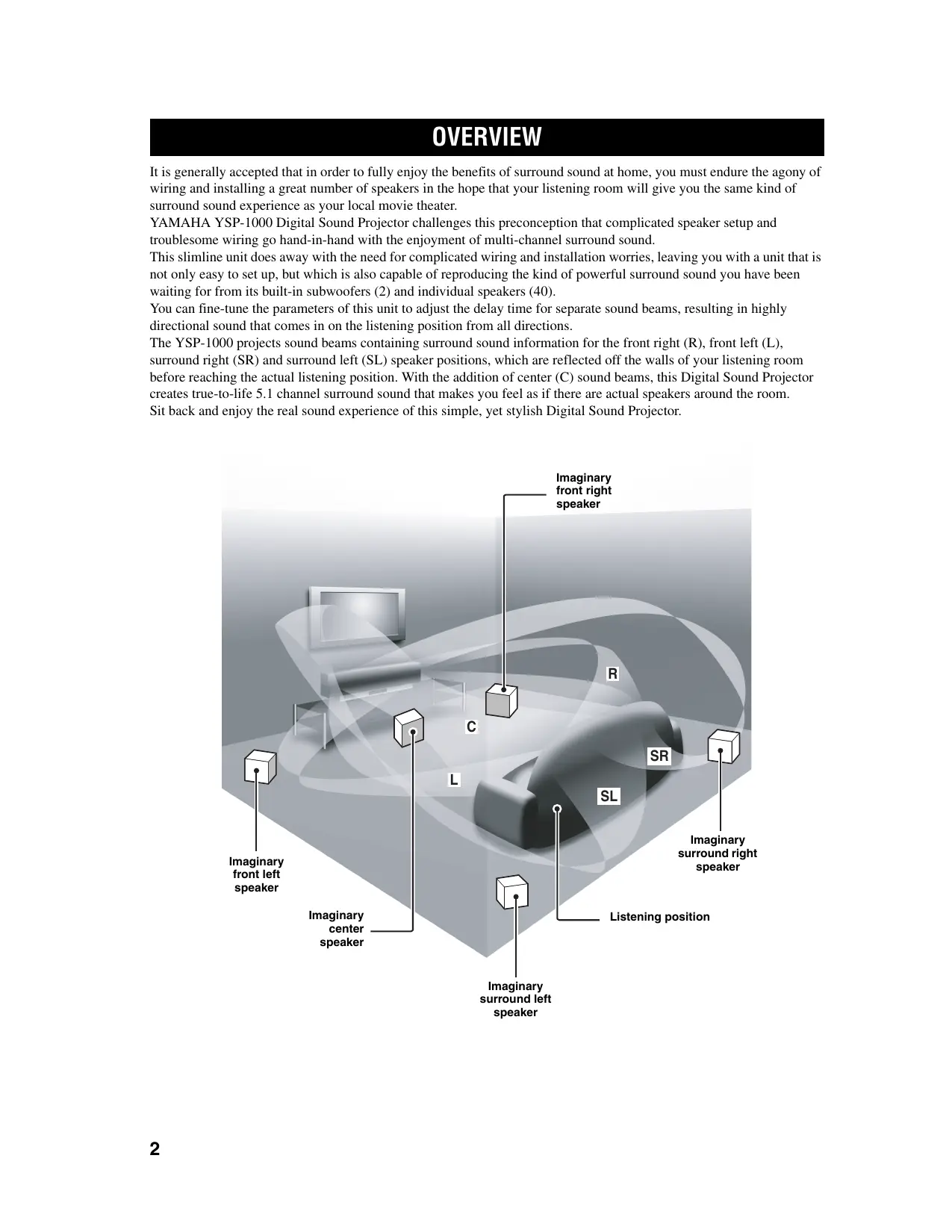
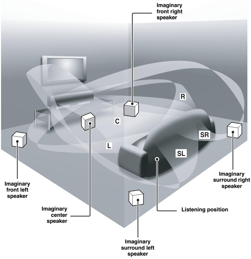
The YSP-1000 projects sound beams containing surround sound information for the front right (R), front left (L), surround right (SR) and surround left (SL) speaker positions, which are reflected off the walls of your listening room before reaching the actual listening position. With the addition of center (C) sound beams, this Digital Sound Projector creates true-to-life 5.1 channel surround sound that makes you feel as if there are actual speakers around the room. Sit back and enjoy the real sound experience of this simple, yet stylish Digital Sound Projector.
text_image
Imaginary front left speaker Imaginary center speaker Imaginary surround left speaker Imaginary surround right speaker Imaginary front right speaker C L R SR SL Listening positionFEATURES
Digital Sound Projector
This unit employs the digital sound projector technology that allows one slim unit to control and steer multiple channels of sound to generate full, physical 5.1 channel surround sound, thus eliminating the need for satellite loudspeakers and cabling normally associated with conventional surround sound systems. This unit is also equipped with the following 5 beam modes so that you can choose the behavior of sound beams that best matches your listening environment.
◆ 5 beam mode
◆ ST(STEREO)+3 beam mode
◆ 3 beam mode
◆ Stereo mode
◆ Target mode
Cinema DSP Digital
This unit employs the Cinema DSP Digital technology developed by YAMAHA Electronics Corp. so that you can experience movies at home with all the dramatic sound impact that the director intended to convey.
OSD (on-screen display)
This unit employs the OSD which is basically a superimposed screen image displayed on your video monitor. The OSD is used to display the system information or adjust settings for the system parameters.
Versatile Remote Control
The supplied remote control come with preset remote control codes to be used to control the DVD player, VCR, cable TV tuner and digital satellite tuner connected to this unit. In addition, the remote control is equipped with the macro capability so that you can perform a series of operations with the press of a single button.

The “CINEMADSP” logo and “Cinema DSP” are registered trademarks of YAMAHA Corporation.

Manufactured under license from Dolby Laboratories.
“Dolby”, “Pro Logic”, and the double-D symbol are trademarks of Dolby Laboratories.

“DTS”, and “Neo:6” are trademarks of Digital Theater Systems, Inc.
AUTO SETUP
This unit employs the automatic sound beam optimization using the YAMAHA Parametric Room Acoustic Optimizer (YPAO) technology with the aid of the supplied optimizer microphone so that you can avoid troublesome listening-based speaker setup and achieve highly accurate sound beam adjustments that best match your listening environment.
Compatibility with the Newest Technologies
This unit employs decoders compatible with Dolby Digital, DTS (Digital Theater Systems), Dolby Pro Logic, Dolby Pro Logic II and DTS Neo:6.
♦ Dolby Digital
This is the standard audio signal format used on DVDs and other purely digital media. This surround technology deliver high-quality digital audio for up to 5.1 discrete channels to produce a directional and more realistic effect.
◆ DTS (Digital Theater Systems)
This is an audio signal format used on DVDs and other purely digital media. This surround technology deliver high-quality digital audio for up to 5.1 discrete channels to produce a directional and more realistic effect.
♦ Dolby Pro Logic
This sophisticated, matrix decoding technology up-converts any 2 channel source audio to a surround sound playback.
♦ Dolby Pro Logic II
This is fundamentally a redesigned version of Dolby Pro Logic that employs 2 stereo surround channels, a subwoofer and a greatly enhanced steering logic. As a result, this improved technology provides an exceptionally stable sound field that simulates 5.1 to a much greater degree than the original Dolby Pro Logic. In addition, Dolby Pro Logic II features Movie, Music and Game modes specifically designed for movies, music and games respectively.
◆ DTS Neo:6
This technology decodes the conventional 2 channel sources for maximum 6 channel playback, enabling playback with the full-range channels with higher separation. This unit is equipped with the 5 channel playback mode. Music mode and Cinema mode are available to play back music and movie sources respectively.

Manufactured under license from 1 Ltd. Worldwide patents applied for.
The ‘1’ logo and ‘Digital Sound Projector™’ are trademarks of 1 Ltd.

TruBass, SRS and the “(●)” symbol are registered trademarks of SRS Labs, Inc. TruBass technology is incorporated under license from SRS Labs, Inc.
USING THIS MANUAL
Notes
- This manual describes how to connect and operate this unit. For details regarding the operation of external components, refer to the supplied owner's manual for the component.
- Some operations can be performed by using either the buttons on the main unit or on the remote control. In such cases, the operation is described using remote control operation.
- 📋 indicates a tip for your operation.
- This manual is printed prior to production. Design and specifications are subject to change in part as a result of improvements, etc. In case of differences between the manual and product, the product has priority.
1 Install this unit in your listening room.
See "INSTALLATION" on page 11.

2 Connect this unit to your TV and other external components.
See “CONNECTIONS” on page 15.

3 Prepare the remote control and turn on the power of this unit.
See “GETTING STARTED” on page 24.

4 Run AUTO SETUP.
See “AUTO SETUP” on page 28.

5 Play back a source and enjoy surround sound.
See "PLAYBACK" on page 39.

If you want to make additional settings and adjustments
6 Run MANUAL SETUP and set remote control codes to fine-tune settings.
See “MANUAL SETUP” on page 68 and “REMOTE CONTROL FEATURES” on page 87.
SUPPLIED ACCESSORIES
Check that you have received all of the following parts.
Remote control (×1)
text_image
STANDBY/ON (V/I) POWER AV POWER TV DVD VCR STB TV INPUT1 TV INPUT2 MACRO AUX (●) INPUT/MODE SLEEP YSP SBEAM ST-3BEAM 3BEAM 1 2 3 STEREO TARGET 4 5 6 MUSIC MOVIE VOL MODE 7 8 9 SPORTS OFF SURROUND 0 +10 CH LEVEL CINEMA DSP MENU TEST ENTER RETURN VOLUME CH TV VOL + + + - - - - - MUTE TV INPUT TV MUTE CODE SET ◀◀ ▶▶▶> ◀◀ □ □□ ▶▶▶▶> YAMAHABatteries (×2) (AA, R6, UM-3)
Video pin cable (×1)
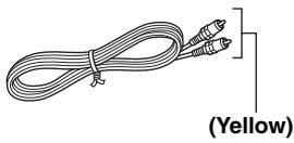
natural_image
Coiled cable with two connectors, labeled (Yellow) at the bottom (no other text or symbols)Optimizer microphone (×1)
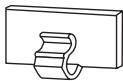
Cable clamp (×1)
Cardboard microphone stand (×1)
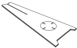
natural_image
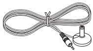
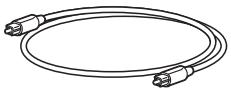
Technical line drawing of a metal plate with a circular cutout and four holes (no text or symbols)Optical cable (×1)
Digital audio pin cable (×1)
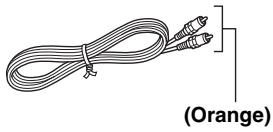
natural_image
Line drawing of a coiled cable with two connectors, labeled (Orange) at the bottom (no other text or symbols)Audio pin cable (×1)
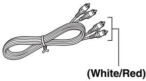
natural_image
Coiled cable with three connectors, labeled (White/Red) at the bottom (no other text or symbols)Fastener (×4)
Power supply cable (×1)
natural_image
Simple line drawing of a coiled cable with two connectors (no text or symbols)CONTROLS AND FUNCTIONS
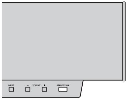
Front panel
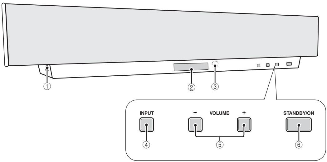
text_image
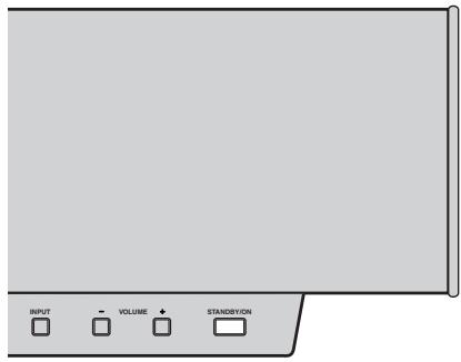
INPUT - VOLUME + STANDBY/ON ④ ⑤ ⑥① OPTIMIZER MIC jack
Use to connect the supplied optimizer microphone to be used to run AUTO SETUP (see page 28).
② Front panel display
Shows information about the operational status of this unit.
③ Remote control sensor
Receives infrared signals from the remote control.
④ INPUT
Press repeatedly to switch between input sources (TV, STB, VCR, DVD or AUX). See page 39 for details.
⑤ VOLUME -/+
Controls the volume level of all audio channels (see page 40).
⑥ STANDBY/ON
Turns on the power of this unit or sets it to the standby mode (see page 25).
Notes
- When you turn on the power of this unit, you will hear a click and there will be a 4 to 5-second delay before it can reproduce sound.
- In the standby mode, this unit consumes a small amount of power in order to receive infrared-signals from the remote control.
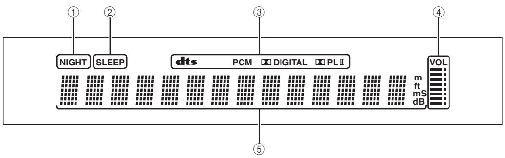
Front panel display
flowchart
graph TD
    A["NIGHT"] --> B["SLEEP"]
    B --> C["dts"]
    C --> D["PCM"]
    D --> E["Digital"]
    E --> F["PL II"]
    F --> G["VOL"]
    G --> H["m ft ms dB"]
    style A fill:#f9f,stroke:#333
    style B fill:#f9f,stroke:#333
    style C fill:#ccf,stroke:#333
    style D fill:#ccf,stroke:#333
    style E fill:#ccf,stroke:#333
    style F fill:#ccf,stroke:#333
    style G fill:#cfc,stroke:#333
    style H fill:#fcc,stroke:#333
① NIGHT indicator
Lights up when you select a volume mode (see page 56).
② SLEEP indicator
Lights up when the sleep timer is turned on (see page 60).
③ Decoder indicators
Light up when the corresponding decoder of this unit is in operation (see page 46).
④ Volume level indicator
Shows the current volume level (see page 40).
⑤ Multi-information display
Shows information when you adjust the parameters of this unit.
#
You can adjust the brightness of the front panel display using the DISPLAY MENU parameters in MANUAL SETUP (see page 79).
Rear panel
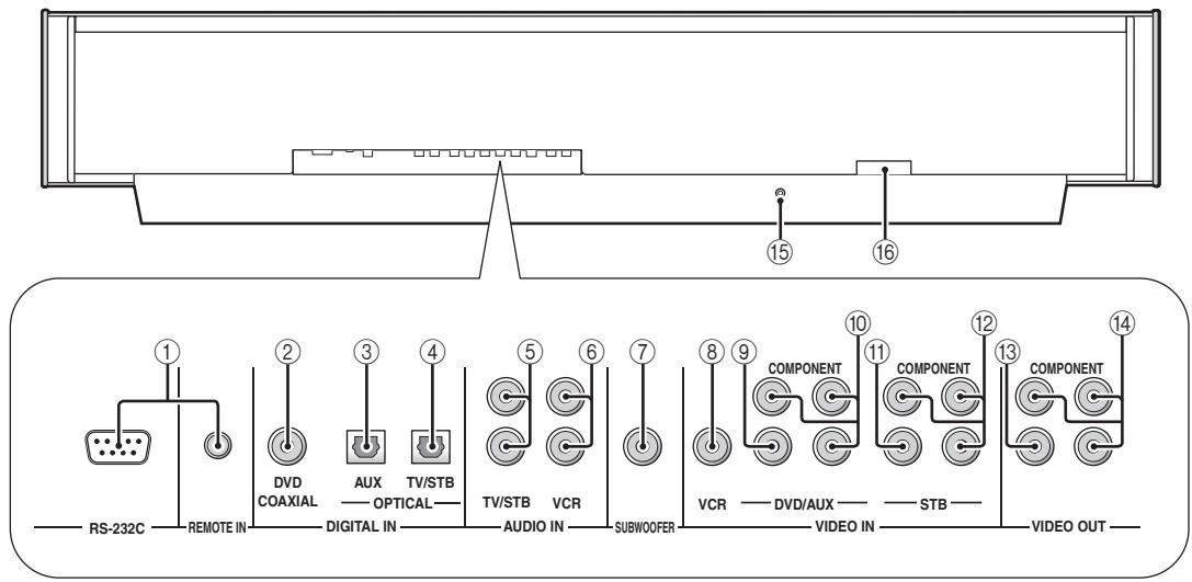
text_image
RS-232C REMOTE IN DVD COAXIAL DIGITAL IN AUX OPTICAL TV/STB TV/STB VCR AUDIO IN SUBWOOFER COMPONENT VCR VIDEO IN COMPONENT STB VIDEO OUT COMPONENT 15 16 1 2 3 4 5 6 7 8 9 10 11 12 13 14① RS-232C/REMOTE IN terminals
These are control expansion terminals for factory use only (see page 23).
② DVD COAXIAL DIGITAL IN jack
Use to connect a DVD player/recorder via a coaxial digital connection (see page 17).
③ AUX OPTICAL DIGITAL IN jack
Use to connect an external component via an optical digital connection (see page 21).
④ TV/STB OPTICAL DIGITAL IN jack
Use to connect a TV, a digital satellite tuner or a cable TV tuner via an optical digital connection (see page 16, 19 and 20).
⑤ TV/STB AUDIO IN jacks
Use to connect a TV, a digital satellite tuner or a cable TV tuner via an analog audio connection (see page 16, 19 and 20).
⑥ VCR AUDIO IN jacks
Use to connect a VCR via an analog audio connection (see pages 17 and 18).
⑦ SUBWOOFER jack
Use to connect a subwoofer (see page 22).
⑧ VCR VIDEO IN jack
Use to connect a VCR via a composite analog video connection (see page 18).
⑨ DVD/AUX VIDEO IN jack
Use to connect a DVD player/recorder or an external component via a composite analog video connection (see page 17).
⑩ DVD/AUX COMPONENT VIDEO IN jacks
Use to connect a DVD player/recorder or an external component via a component analog video connection (see page 17).
⑪ STB VIDEO IN jack
Use to connect a digital satellite tuner or a cable TV tuner via a composite analog video connection (see pages 19 and 20).
⑫ STB COMPONENT VIDEO IN jacks
Use to connect a digital satellite tuner or a cable TV tuner via a component analog video connection (see pages 19 and 20).
⑬ VIDEO OUT jack
Use to connect to the video input jack of your TV via a composite analog video connection to display the OSD of this unit (see page 16).
⑭ COMPONENT VIDEO OUT jacks
Use to connect to the video input jacks of your TV via a component analog video connection to display the OSD of this unit (see page 16).
⑮ IR-OUT terminal
This is a control expansion terminal for factory use only (see page 23).
⑯ AC IN
Use to connect the supplied power supply cable (see page 23).
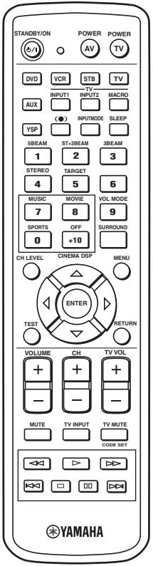
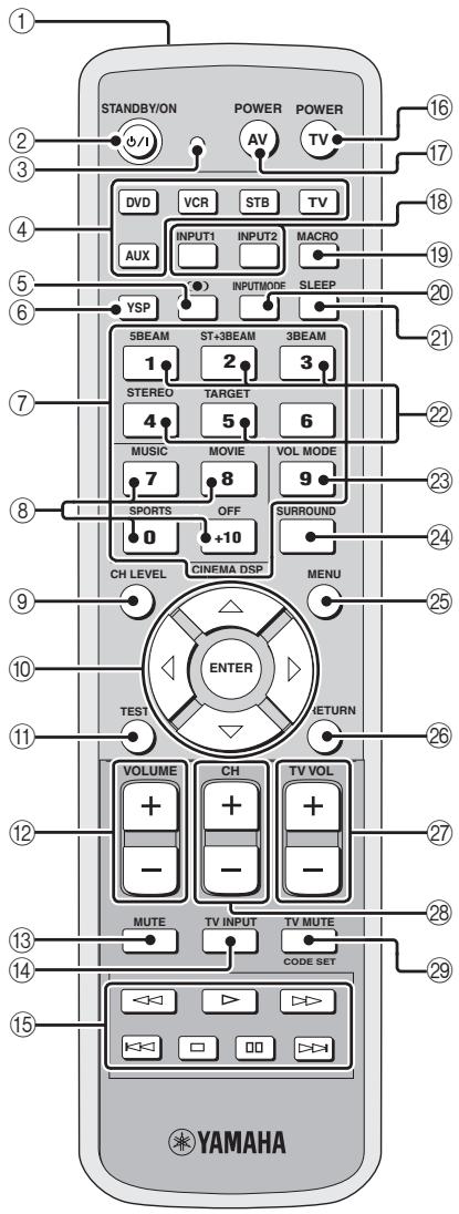
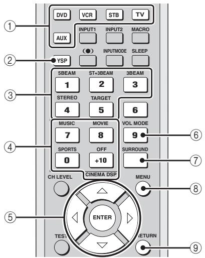
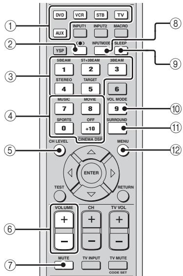
Remote control
This section describes the function of each control on the remote control used to control this system.

You can also control other components using the remote control once you set the appropriate remote control codes. See “Controlling other components” on page 88 for details.
text_image
STANDBY/ON POWER POWER AV TV DVD VCR STB TV INPUT1 INPUT2 MACRO AUX YSP SLEEP INPUTMODE 5BEAM ST+3BEAM 3BEAM 1 2 3 STEREO TARGET 4 5 6 MUSIC MOVIE VOL MODE 7 8 9 SPORTS OFF SURROUND 0 +10 CH LEVEL CINEMA DSP MENU ENTER TEST RETURN VOLUME CH TV VOL + - - - - - MUTE TV INPUT TV MUTE CODE SET YAMAHA① Infrared window
Outputs infrared control signals. Aim this window at the component you want to operate.
② STANDBY/ON
Sets this system to the standby mode (see page 25).
③ Transmission indicator
Lights up when infrared control signals are being output.
④ Input selector buttons
Use to select an input source (TV, STB, VCR, DVD or AUX) and change the control area (see page 39).
⑤ (●) TruBass
Use to effectively reproduce the bass sound (see page 58).
⑥ YSP
Switches to the operation mode of this unit.
⑦ Numeric buttons
Use to enter numbers.
⑧ Sound field program buttons
Use to select sound field programs (see page 51).
⑨ CH LEVEL
Adjusts the volume level of each channel (see page 84).
⑩ Cursor buttons △ / ▽ / ◀ / ▷, ENTER
Use to select and adjust SET MENU items.
⑪ TEST
Outputs a test tone when adjusting the output level of each speaker (see page 83).
⑫ VOLUME +/-
Increases or decreases the volume level of this unit (see page 40).
⑬ MUTE
Mutes the sound. Press again to restore the audio output to the previous volume level (see page 41).
⑭ TV INPUT
Switches the input source of the TV (see page 88).
⑮ DVD player/VCR control buttons
Use to control the DVD player of the VCR (see pages 88 and 89).
⑯ TV POWER
Turns on the power of the TV or sets it to the standby mode (see page 88).
⑰ AV POWER
Turns on the power of the selected component or sets it to the standby mode (see pages 88 and 89).
⑱ INPUT1/INPUT2
Selects the input source of the TV.
⑲ MACRO
Use to set the TV macro (see page 90).
⑳ INPUTMODE
Switches between input modes (AUTO, DTS or ANALOG). See page 39 for details.
②1 SLEEP
Sets the sleep timer (see page 60).
⑳ Beam mode buttons
Change the beam mode settings (see page 42).
②3 VOL MODE
Turns on or off the volume modes (see page 56).
⑳ SURROUND
Selects the surround mode for playback (see page 46).
⑳ MENU
Displays the setup menu on your TV monitor (see pages 31, 62 and 69).
Note
The DVD menu is displayed when DVD is selected as the input source.
②6 RETURN
Use to select sleep timer settings or return to the previous SET MENU screen.
⑳ TV VOL +/-
Adjusts the volume level of the TV (see page 88).
⑳ CH +/-
Switches between channels of the TV or the VCR (see pages 88 and 89).
⑲ TV MUTE, CODE SET
Mutes the audio output of the TV (see page 88).
Use to set up remote control codes (see page 87).
INSTALLATION
This section describes a suitable installation location to install the unit using a metal wall bracket, a rack or a stand.
Before installing this unit
This unit creates surround sound by reflecting projected sound beams off the walls of your listening room. The surround sound effects produced by this unit may not be sufficient when the unit is installed in the following locations.
- Rooms with surfaces inadequate for reflecting sound beams
• Rooms with acoustically absorbent surfaces - Rooms with measurements outside the following range W (3 to 7 m) x H (2 to 3.5 m) x D (3 to 7 m)
- Rooms with less than 2 m from the listening position to the speaker positions
- Rooms where objects such as furniture are likely to obstruct the path of sound beams
• Rooms where the listening position is close to the walls - Rooms where the listening position is not in front of this unit
Make sure you leave an adequate amount of ventilation space so that heat can escape. Make at least 5 cm of space above or below this unit.
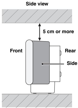
text_image
Side view 5 cm or more Front Rear SideNotes
- This unit weighs 13.0kg . Be sure to install this unit where it will not fall subject to vibrations, such as from an earthquake, and where it is out of the reach of children.
- When using a cathode-ray tube (CRT) TV, do not install this unit directly above your TV.
- This unit is shielded against magnetic rays. However, if the picture on your TV screen becomes blurred or distorted, we recommend moving the speakers away from your TV.
Installing this unit
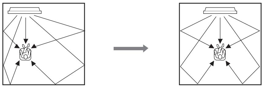
Install this unit where there are no obstacles such as furniture obstructing the path of sound beams. Otherwise, the desired surround sound effects may not be achieved. You may install this unit in parallel with the wall or in the corner.
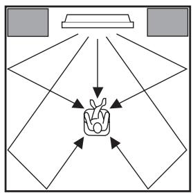
Parallel installation
Install this unit in the exact center of the wall when it is measured from the left and right corners.
flowchart
graph TD
    A["Top Left"] --> B["Central Object"]
    C["Top Right"] --> B
    D["Bottom Left"] --> B
    E["Bottom Right"] --> B
    F["Bottom Left"] --> B
    G["Bottom Right"] --> B
    H["Bottom Left"] --> B
    I["Bottom Right"] --> B
    J["Bottom Left"] --> B
    K["Bottom Right"] --> B
    L["Bottom Left"] --> B
    M["Bottom Right"] --> B
    N["Bottom Left"] --> B
    O["Bottom Right"] --> B
    P["Bottom Left"] --> B
    Q["Bottom Right"] --> B
    R["Bottom Left"] --> B
    S["Bottom Right"] --> B
    T["Bottom Left"] --> B
    U["Bottom Right"] --> B
    V["Bottom Left"] --> B
    W["Bottom Right"] --> B
    X["Bottom Left"] --> B
    Y["Bottom Right"] --> B
    Z["Bottom Left"] --> B
    AA["Bottom Right"] --> B
    AB["Bottom Left"] --> B
    AC["Bottom Right"] --> B
    AD["Bottom Left"] --> B
    AE["Bottom Right"] --> B
    AF["Bottom Left"] --> B
    AG["Bottom Right"] --> B
    AH["Bottom Left"] --> B
    AI["Bottom Right"] --> B
    AJ["Bottom Left"] --> B
    AK["Bottom Right"] --> B
    AL["Bottom Left"] --> B
    AM["Bottom Right"] --> B
    AN["Bottom Left"] --> B
    AO["Bottom Right"] --> B
    AP["Bottom Left"] --> B
    AQ["Bottom Right"] --> B
    AR["Bottom Left"] --> B
    AS["Bottom Right"] --> B
    AT["Bottom Left"] --> B
    AU["Bottom Right"] --> B
    AV["Bottom Left"] --> B
    AW["Bottom Right"] --> B
    AX["Bottom Left"] --> B
    AY["Top Left"]
    AZ["Top Right"]
    BA["Top Left"]
    BB["Top Right"]
    BC["Top Left"]
    BD["Top Right"]
    BE["Top Left"]
    BF["Top Right"]
    BG["Top Left"]
    BH["Top Right"]
    BI["Top Left"]
    BJ["Top Right"]
    BK["Top Left"]
    BL["Top Right"]
    BM["Top Left"]
    BN["Top Right"]
    BO["Top Left"]
    BP["Top Right"]
    BQ["Top Left"]
    BR["Top Right"]
    BS["Top Left"]
    BT["Top Right"]
    BU["Top Left"]
    BV["Top Right"]
    BW["Top Left"]
    BX["Top Right"]
    BY["Top Left"]
    BZ["Top Right"]
    CA["Top Left"]
    CB["Top Right"]
    CC["Top Left"]
    CD["Top Right"]
    CE["Top Left"]
    CF["Top Right"]
    BG<fcel>B<nl>
<fcel>B<fcel>B<nl>
<fcel>B<fcel>B<nl>
<fcel>B<fcel>B<nl>
<fcel>B<fcel>B<nl>
<fcel>B<fcel>B<nl>
<fcel>B<fcel>B<nl>
<fcel>B<fcel>B<nl>
<fcel>B<fcel>B<nl>
<fcel>B<fcel>B<nl>
<fcel>B<fcel>B<nl>
<fcel>B<fcel>B<nl>
<fcel>B<fcel>B<nl>
<fcel>B<fcel>B<nl>
<fcel>B<fcel>B<nl>
<fcel>B<fcel>B<nl>
<fcel>B<fcel>B<nl>
<fcel>B<fcel>B<nl>

An object, such as furniture
■ Corner installation
Install this unit in the corner at a 40^ to 50^ angle from the adjacent walls.
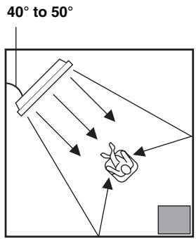
text_image
40° to 50°
An object, such as furniture
#
The availability of the beam mode depends on the installation location of this unit (see page 42). All five beam modes are available for the parallel installation whereas the 3 beam and 5 beam modes are not available for the corner installation.
■ Installation examples
Example 1
Install this unit as close to the exact center of the wall as possible.
flowchart
graph TD
    A["Device"] --> B["Input"]
    B --> C{Output}
    C --> D["Final Product"]

    subgraph Left
        E["Input"] --> F["Device"]
        G["Output"] --> H["Device"]
    end

    subgraph Right
        I["Input"] --> J["Device"]
        K["Output"] --> L["Device"]
    end
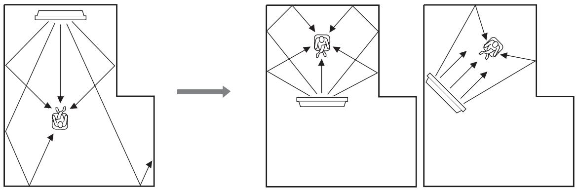
Example 2
Install this unit so that the sound beams can be reflected off the walls.
flowchart
graph TD
    A["Object Detection"] --> B["Object Tracking"]
    B --> C["Object Projection"]
    C --> D["Object Output"]
    style A fill:#f9f,stroke:#333
    style B fill:#ccf,stroke:#333
    style C fill:#cfc,stroke:#333
    style D fill:#fcc,stroke:#333
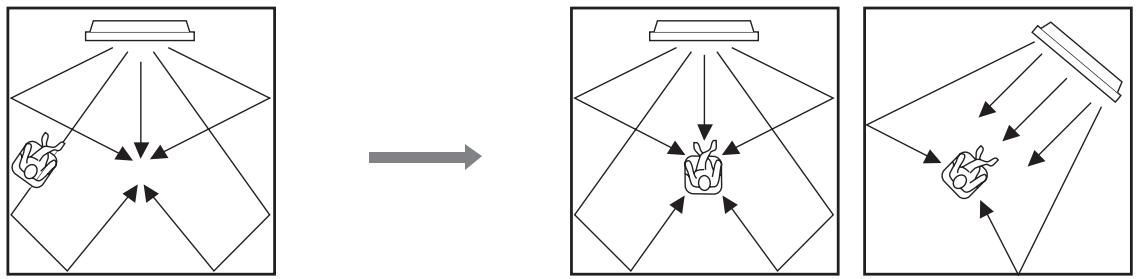
Example 3
Install this unit as close to the exact front of your normal listening position.
flowchart
graph TD
    A["Hand gestures"] --> B["Object"]
    C["Arrow"] --> B
    B --> D["Arrow to top panel"]
    B --> E["Arrow to bottom panel"]
    D --> F["Final object with hand gesture"]
    E --> G["Final object with hand gesture"]
    style A fill:#f9f,stroke:#333
    style C fill:#f9f,stroke:#333
    style B fill:#ccf,stroke:#333
    style D fill:#ccf,stroke:#333
    style E fill:#ccf,stroke:#333
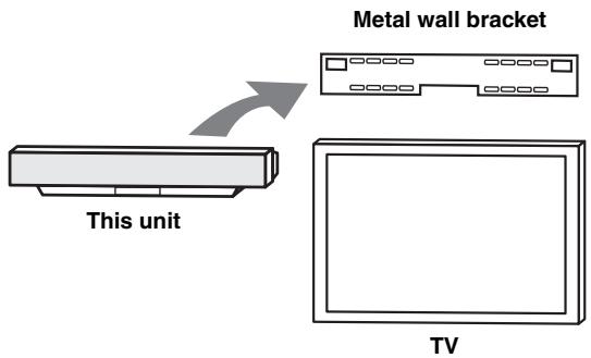
■ Using a metal wall bracket
You can use the optional metal wall bracket to mount this unit on the wall in your listening room.
text_image
Metal wall bracket This unit TV
Refer to the instructions supplied with the metal bracket for details on how to attach the metal bracket to the wall or how to attach this unit to the metal bracket.
■ Using a stand
You can mount your TV on the stand placed on a commercially available rack to install this unit under your TV.
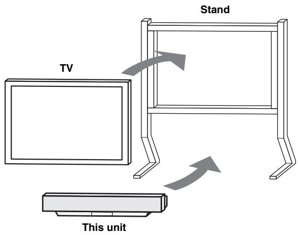
text_image
Stand TV This unit
Refer to the instructions supplied with the stand for details on how to install the stand or how to mount this unit and the TV on the stand.
■ Using a TV stand
You can use the optional TV stand to install this unit. For detailed information on installing this unit using a TV stand, refer to the installation manual supplied with the optional TV stand.
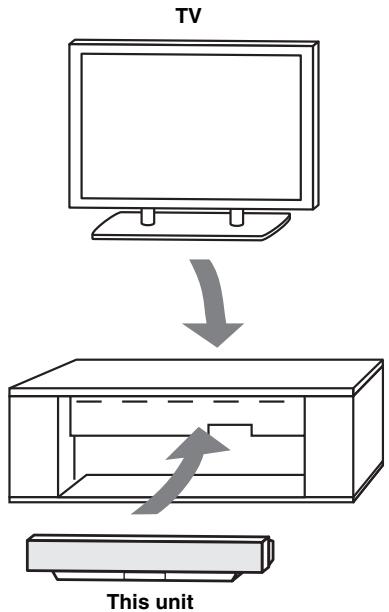
text_image
TV This unit■ Using a rack
You can install this unit either above or under your TV in a commercially available rack.
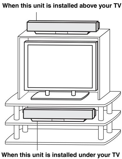
text_image
When this unit is installed above your TV When this unit is installed under your TVNote
Make sure that the rack is large enough to allow adequate ventilation space around this unit (see page 11) and that it is strong enough to support the weight of both this unit and your TV.
■ Affixing this unit
Peel off the film from each of the four supplied fasteners and then secure them to the bottom four corners of this unit and the top of the rack, etc.
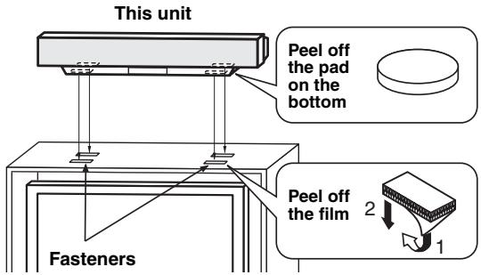
text_image
This unit Peel off the pad on the bottom Fasteners Peel off the film 2 1Notes
- Do not install this unit on top of a slanted surface. This unit may fall over and cause injury.
- Make sure you wipe the surface of the rack, etc. before securing the fasteners. Applying the tape to a dirty or wet surface will weaken the sticking power of the tape, and this unit may fall as a result.
CONNECTIONS
This unit is equipped with the following types of audio/video input/output jacks:
For audio input
• 2 optical digital input jacks
• 1 coaxial digital input jack
• 2 sets of analog input jacks
For video input
• 3 composite analog input jacks
• 2 sets of component analog input jacks
For video output
• 1 composite analog output jack
• 1 set of component analog output jacks
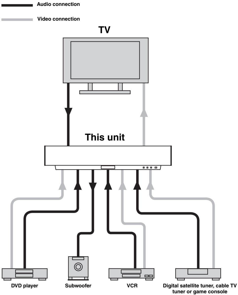
Use these audio/video input/output jacks to connect external components such as your TV, DVD player, VCR, digital satellite tuner, cable TV tuner and game console. Further, by connecting a subwoofer to this unit, you can enjoy reinforced low bass sounds. For details on how to connect various types of external components to this unit, see pages 16 to 22.
CAUTION
Do not connect this unit or other components to the main power until all connections between components are complete.
flowchart
graph TD
    TV["TV"] -->|Audio connection| A["This unit"]
    TV -->|Video connection| B["Subwoofer"]
    TV --> C["VCR"]
    TV --> D["DVD player"]
    TV --> E["Digital satellite tuner, cable TV tuner or game console"]
Connecting a TV
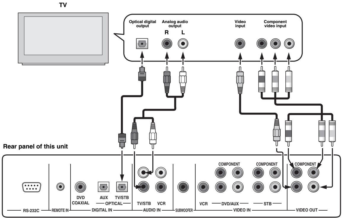
Connect a TV to this unit and display the OSD for easy viewing when you adjust the system parameters in SET MENU.
■ Audio connections
Connect the analog audio output jacks of your TV to the TV/STB AUDIO IN jacks of this unit. If your TV has an optical digital output jack, connect the optical digital output jack of your TV to the TV/STB OPTICAL DIGITAL IN jack of this unit in addition to the analog audio connection. Once the digital audio connection is made, digital audio signals can be input to this unit during digital broadcasting.
■ Video connections
Connect the video input jacks of your TV to the VIDEO OUT jacks of this unit. If your TV has component video input jacks, connect the component video input jacks of your TV to the COMPONENT VIDEO OUT jacks of this unit in addition to the composite video connection. Once the component video connection is made, you can enjoy images with better resolution.

- The circuits of composite and component video signals are independent of each other.
- To prevent the optical cable from being unplugged, affix the optical cable in the supplied cable clamp (see page 23).
Note
If you connect this unit to the analog audio and optical digital audio output jacks at the same time as shown in the left illustration below, the digital audio signals output at the optical digital output jack take priority over the analog audio signals output at the analog audio output jacks.
flowchart
graph TD
    TV["TV"] --> A["Optical digital output"]
    TV --> B["Analog audio output"]
    TV --> C["Video input"]
    TV --> D["Component video input"]
    A --> E["Antenna"]
    B --> F["Analog audio"]
    C --> G["Video"]
    D --> H["Component"]
    E --> I["Microcontroller"]
    F --> I
    G --> I
    H --> I
    I --> J["Antenna"]
    I --> K["Analog audio"]
    I --> L["Video"]
    I --> M["Component"]
    J --> N["Antenna"]
    K --> O["Analog audio"]
    L --> P["Video"]
    M --> Q["Component"]
    N --> R["Antenna"]
    O --> S["Analog audio"]
    P --> T["Video"]
    Q --> U["Component"]
Cables used for audio connections
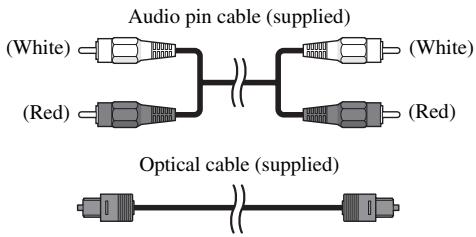
text_image
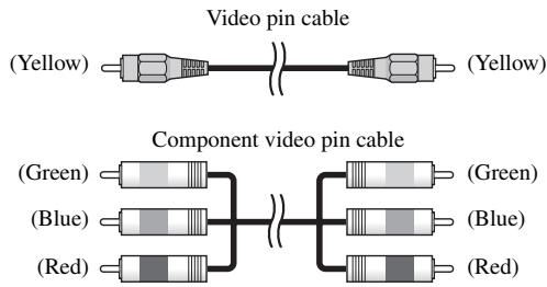
Audio pin cable (supplied) (White) (Red) (White) (Red) Optical cable (supplied)Cables used for video connections
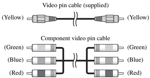
text_image
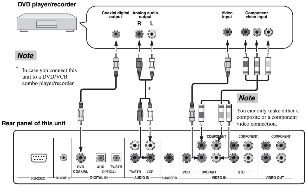
Video pin cable (supplied) (Yellow) Component video pin cable (Green) (Green) (Blue) (Blue) (Red) (Red)Connecting a DVD player/recorder
Connect a DVD player/recorder and enjoy DVDs.
Audio connections
Connect the optical digital output jack of your DVD player/recorder to the DVD COAXIAL DIGITAL IN jack of this unit. In case you connect this unit to a DVD/VCR combo player/recorder, connect the analog audio output jacks of your DVD/VCR combo player/recorder to the VCR AUDIO IN jacks of this unit in addition to the optical digital audio connection.
■ Video connections
Connect the video output jack of your DVD player/recorder to the DVD/AUX VIDEO IN jack of this unit. If your DVD player/recorder has component video output jacks, connect the component video output jacks of your DVD player/recorder to the DVD/AUX COMPONENT VIDEO IN jacks of this unit. Once the component video connection is made, you can enjoy images with better resolution.

To prevent the optical cable from being unplugged, affix the optical cable in the supplied cable clamp (see page 23).
Notes
- Check that your DVD player/recorder is properly set to output Dolby Digital and DTS digital audio signals. If not, adjust the system settings of your DVD player/recorder. For details, refer to the operation manual supplied with your DVD player/recorder.
- If your DVD player/recorder does not have a coaxial digital output jack, make an optical digital audio connection instead (see page 21).
flowchart
graph TD
    A["DVD player/recorder"] --> B["Coaxial digital output"]
    A --> C["Analog audio output"]
    A --> D["Video input"]
    A --> E["Component video input"]
    F["Rear panel of this unit"] --> G["DVDCOAXIAL"]
    F --> H["AUX"]
    F --> I["TV/STB"]
    F --> J["TV/STB"]
    F --> K["VCR"]
    F --> L["AUDIO IN"]
    F --> M["SUBWOOFER"]
    N["Note"] --> O["Component"]
    N --> P["Video IN"]
    N --> Q["STB"]
    R["Note"] --> S["Video OUT"]
    T["* In case you connect this unit to a DVD/VCR combo player/recorder"] --> U["DVDCOAXIAL"]
    T --> V["AUX"]
    T --> W["TV/STB"]
    T --> X["TV/STB"]
    T --> Y["VCR"]
    T --> Z["AUDIO IN"]
    T --> AA["SUBWOOFER"]
    AB["RS-232C"] --> AC["REMOTE IN"]
    AD["DIVDCOAXIAL"] --> AE["DIGITAL IN"]
    AF["AUX"] --> AG["TV/STB"]
    AH["TV/STB"] --> AI["AUDIO IN"]
    AJ["VCR"] --> AK["SUBWOOFER"]
    AL["VCR"] --> AM["DVD/AUX"]
    AN["VIDEO OUT"] --> AO["STB"]
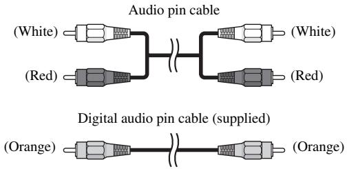
Cables used for audio connections
text_image
Audio pin cable (White) (Red) (White) (Red) Digital audio pin cable (supplied) (Orange) (Orange)Cables used for video connections
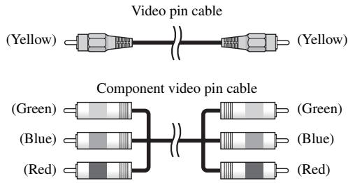
text_image
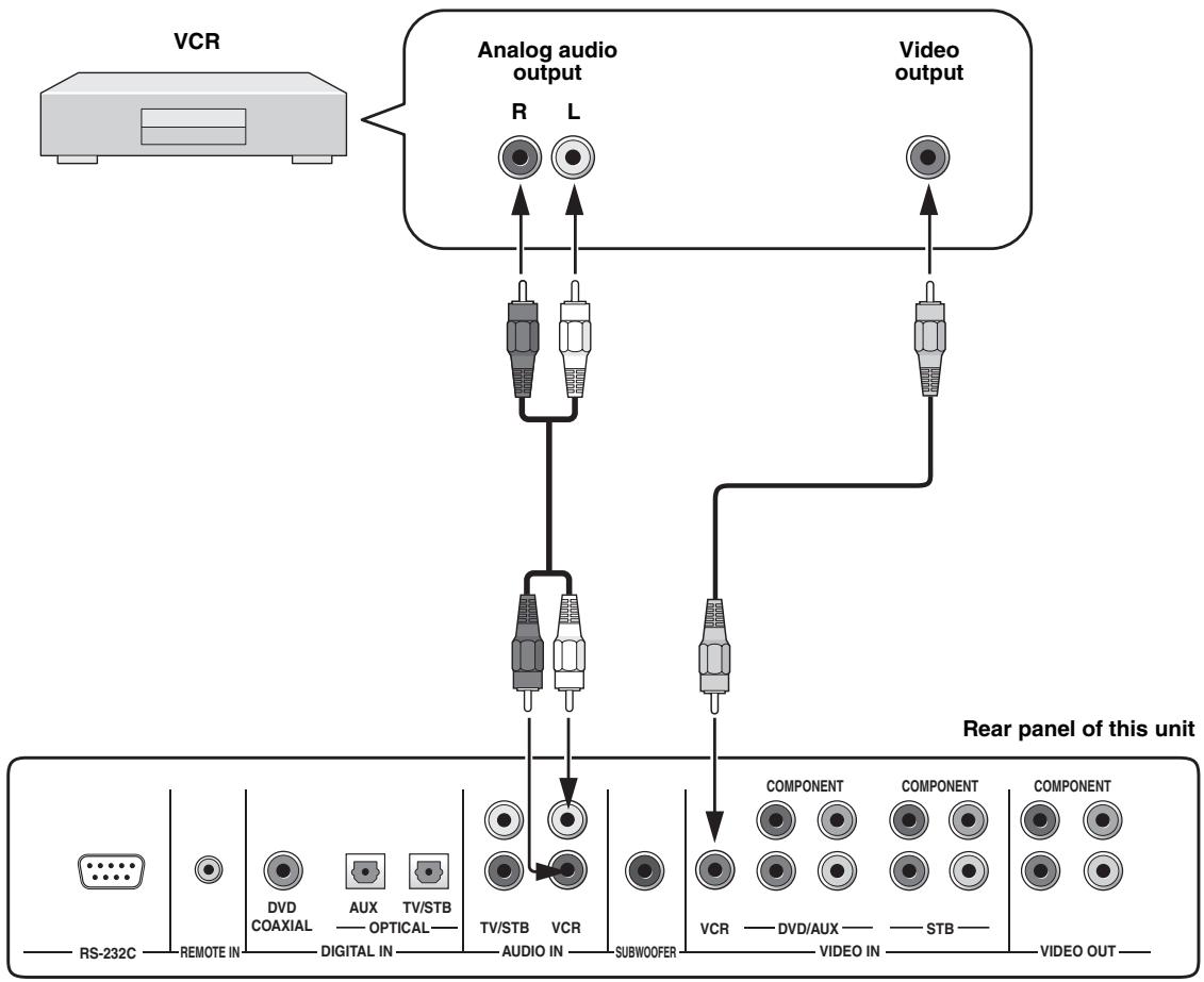
Video pin cable (Yellow) Component video pin cable (Green) (Blue) (Red) (Green) (Blue) (Red)Connecting a VCR
Connect a VCR and enjoy video cassette tapes.
■ Audio connections
Connect the analog audio output jacks of your VCR to the VCR AUDIO IN jacks of this unit.
■ Video connections
Connect the video output jack of your VCR to the VCR VIDEO IN jack of this unit.
Note
Be sure to match the left and right output jacks of your VCR with the left and right input jacks of this unit.
flowchart
graph TD
    A["VCR"] --> B["Analog audio output"]
    B --> C["Video output"]
    B --> D["Component 1"]
    B --> E["Component 2"]
    B --> F["Component 3"]
    B --> G["Component 4"]
    D --> H["Component 1"]
    E --> I["Component 2"]
    F --> J["Component 3"]
    G --> K["Component 4"]
    H --> L["Video OUT"]
    I --> M["Video IN"]
    J --> N["Subwoofer"]
    K --> O["Subwoofer"]
    P["RS-232C"] --> Q["REMOTE IN"]
    Q --> R["DVD COAXIAL"]
    Q --> S["AUX OPTICAL"]
    Q --> T["TV/STB"]
    Q --> U["TV/STB AUDIO IN"]
    Q --> V["VCR"]
    W["Rear panel of this unit"] --> X["Component 1"]
    W --> Y["Component 2"]
    W --> Z["Component 3"]
    W --> AA["Component 4"]
Cables used for audio connections
text_image
Audio pin cable (White) (Red) (White) (Red)Cables used for video connections
text_image
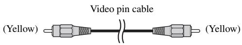
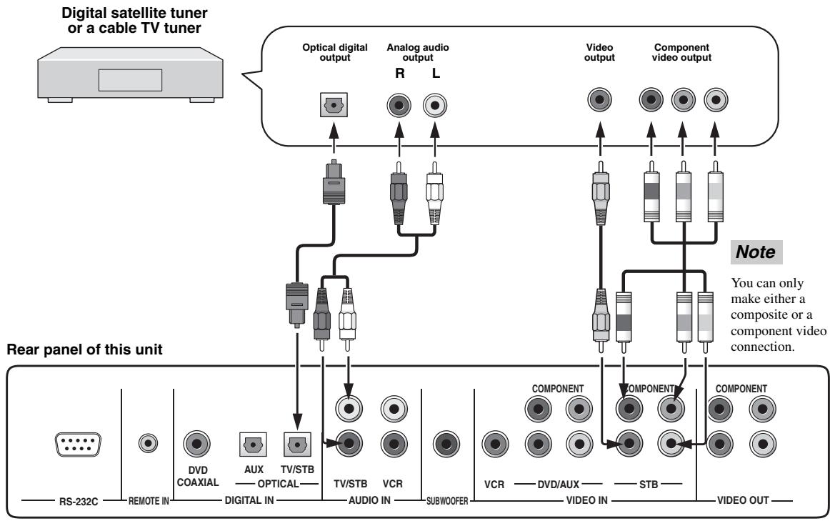
Video pin cable (Yellow) (Yellow)Connecting a digital satellite tuner or a cable TV tuner
Connect a digital satellite tuner or a cable TV tuner and enjoy digital satellite broadcasting or cable TV broadcasting.
■ Audio connections
Connect the optical digital output jack of your digital satellite tuner or cable TV tuner to the TV/STB OPTICAL DIGITAL IN jack of this unit. Connect the analog audio output jacks of your digital satellite tuner or cable TV tuner to the TV/STB AUDIO IN jacks of this unit in addition to the optical digital audio connection.
■ Video connections
Connect the video output jack of your digital satellite tuner or cable TV tuner to the STB VIDEO IN jack of this unit. If your digital satellite tuner or cable TV tuner has component video output jacks, connect the component video output jacks of your digital satellite tuner or cable TV tuner to the STB COMPONENT VIDEO IN jacks of this unit. Once the component video connection is made, you can enjoy images with better resolution.
flowchart
graph TD
    A["Digital satellite tuner or a cable TV tuner"] --> B["Optical digital output"]
    A --> C["Analog audio output"]
    A --> D["Video output"]
    A --> E["Component video output"]
    F["Rear panel of this unit"] --> G["DVDCOAXIAL"]
    F --> H["AUX"]
    F --> I["TV/STB"]
    F --> J["TV/STB"]
    F --> K["VCR"]
    F --> L["AUDIO IN"]
    F --> M["SUBWOOFER"]
    N["Note"] --> O["COMPONENT"]
    N --> P["COMPONENT"]
    N --> Q["VIDEO OUT"]
    style A fill:#f9f,stroke:#333
    style F fill:#ccf,stroke:#333
    style N fill:#cfc,stroke:#333
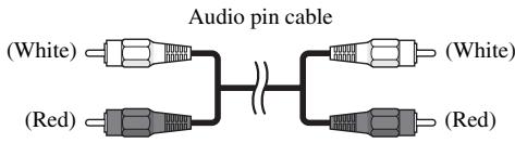
Cables used for audio connections
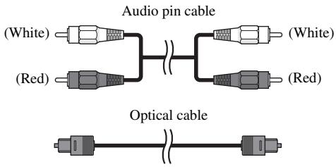
text_image
Audio pin cable (White) (Red) (White) (Red) Optical cableCables used for video connections
text_image
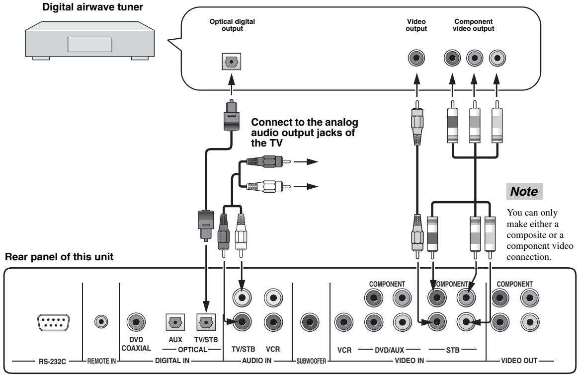
Video pin cable (Yellow) Component video pin cable (Green) (Blue) (Red) (Green) (Blue) (Red)Connecting a digital airwave tuner
If your digital airwave tuner does not support analog broadcasting, make audio/video connections as shown below.
■ Audio connections
Connect the optical digital output jack of your digital airwave tuner to the TV/STB OPTICAL DIGITAL IN jack of this unit. Connect the TV/STB AUDIO IN jacks of this unit to the analog audio output jacks of your TV in addition to the optical digital audio connection between your digital airwave tuner and this unit.
■ Video connections
Connect the video output jack of your digital airwave tuner to the STB VIDEO IN jack of this unit. If your digital airwave tuner has component video output jacks, connect the component video output jacks of your digital airwave tuner to the STB COMPONENT VIDEO IN jacks of this unit. Once the component video connection is made, you can enjoy images with better resolution.
Note
If you want this unit to output audio signals of analog broadcasting, turn off the power of your digital airwave tuner.
flowchart
graph TD
    A["Digital airwave tuner"] --> B["Optical digital output"]
    B --> C["Connect to the analog audio output jacks of the TV"]
    C --> D["Video output"]
    C --> E["Component video output"]
    F["Rear panel of this unit"] --> G["DVDCOAXIAL"]
    F --> H["AUX"]
    F --> I["TV/STB"]
    F --> J["TV/STB"]
    F --> K["VCR"]
    F --> L["AUDIO IN"]
    F --> M["SUBWOOFER"]
    N["Note"] --> O["COMPONENT"]
    N --> P["COMPONENT"]
    Q["Video OUT"] --> R["VIDEO IN"]
    Q --> S["STB"]
    T["RS-232C"] --> U["REMOTE IN"]
    V["DVD COAXIAL"] --> W["DIVDCOAXIAL"]
    X["AUX"] --> Y["DIVDCOAXIAL"]
    Z["TV/STB"] --> AA["DIVDCOAXIAL"]
    AB["Audio IN"] --> AC["DIVDCOAXIAL"]
    AD["Subwoofer"] --> AE["DIVDCOAXIAL"]
Cables used for audio connections
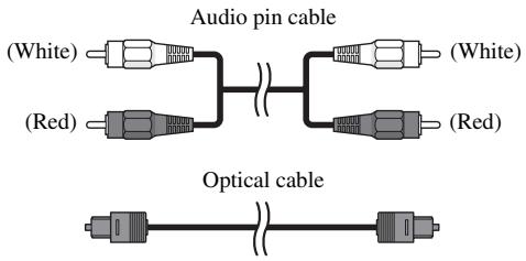
text_image
Audio pin cable (White) (Red) (White) (Red) Optical cableCables used for video connections
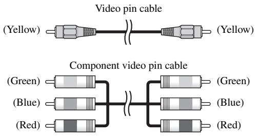
text_image
Video pin cable (Yellow) Component video pin cable (Green) (Blue) (Red) (Green) (Blue) (Red)Connecting other external components
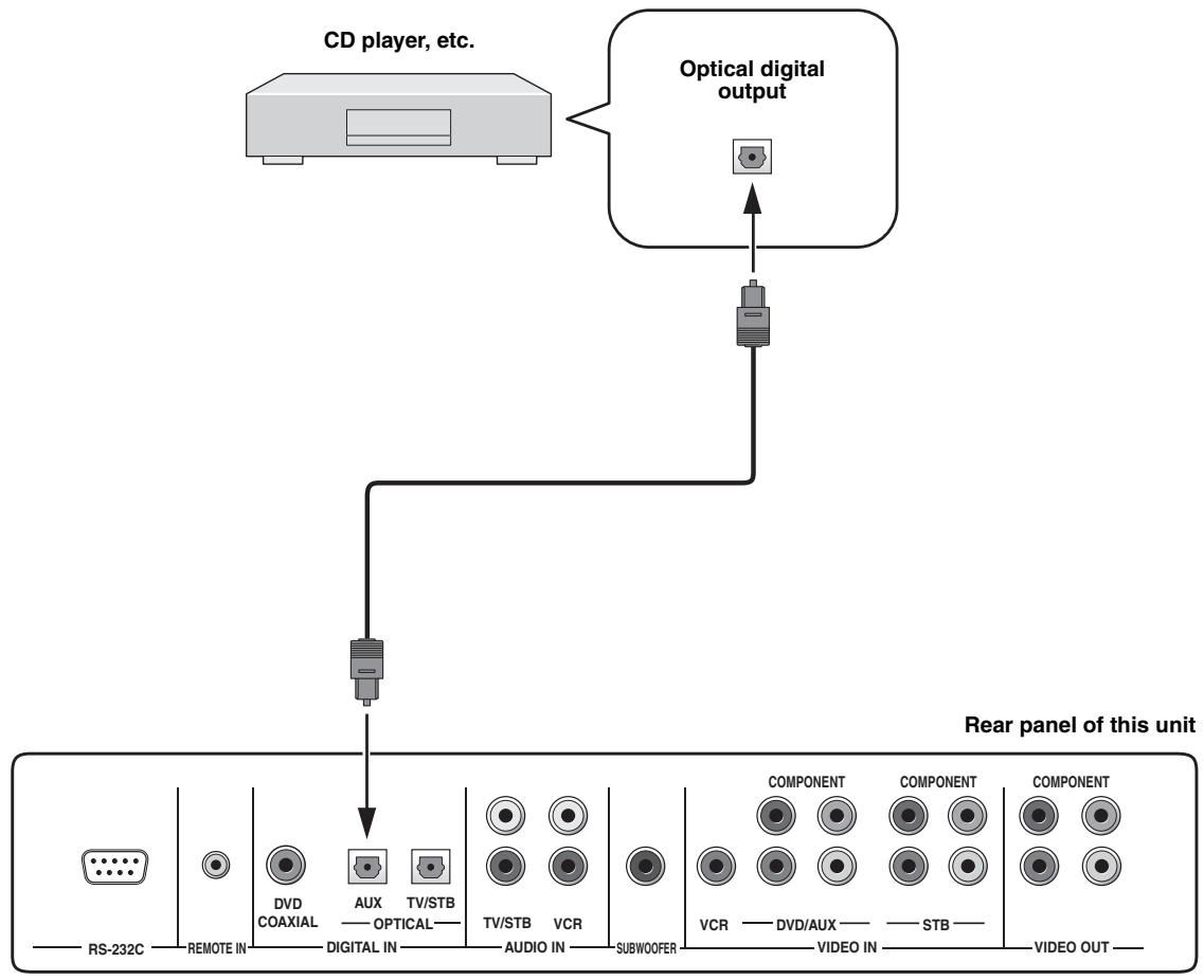
To connect other external components, connect the optical digital output jack of an external component to the AUX OPTICAL DIGITAL IN jack of this unit. Use this connection method to connect an external component that supports an optical digital connection or to connect a DVD player/recorder via an optical digital connection.
Note
If you connect a DVD player/recorder via a coaxial digital connection, adjust settings for INPUT ASSIGNMENT (see page 77).
flowchart
graph TD
    A["CD player, etc."] --> B["Optical digital output"]
    B --> C["Rear panel of this unit"]
    C --> D["RS-232C"]
    C --> E["REMOTE IN"]
    C --> F["DVD COAXIAL"]
    C --> G["AUX"]
    C --> H["TV/STB"]
    C --> I["OPTICAL"]
    C --> J["TV/STB"]
    C --> K["VCR"]
    C --> L["AUDIO IN"]
    C --> M["SUBWOOFER"]
    M --> N["COMPONENT"]
    M --> O["COMPONENT"]
    M --> P["COMPONENT"]
    N --> Q["VCR"]
    O --> R["DVD/AUX"]
    O --> S["STB"]
    P --> T["VIDEO OUT"]
Cables used for connections
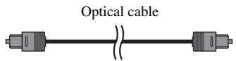
text_image
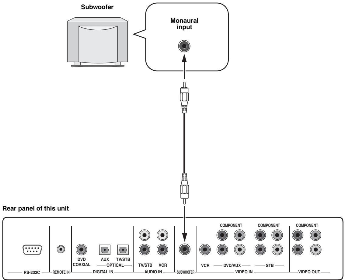
Optical cableConnecting a subwoofer
To connect a subwoofer, connect the monaural input jack of your subwoofer to the SUBWOOFER jack of this unit. If a subwoofer is connected to this unit, turn on the power of your subwoofer and then run AUTO SETUP (see page 28) or select SWFR for BASS OUT in SUBWOOFER SET (see page 75).
flowchart
graph TD
    A["Subwoofer"] --> B["Monaural input"]
    B --> C["Rear panel of this unit"]
    C --> D["RS-232C"]
    D --> E["REMOTE IN"]
    E --> F["DVD COAXIAL"]
    F --> G["AUX —— OPTICAL—"]
    G --> H["TV/STB"]
    H --> I["TV/STB"]
    I --> J["VCR"]
    J --> K["SUBWOOFER"]
    K --> L["COMPONENT"]
    L --> M["COMPONENT"]
    M --> N["VCR —— DVD/AUX —— STB ——"]
    N --> O["VIDEO OUT"]
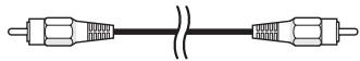
Cables used for connections
Subwoofer pin cable
Affixing the optical cable
To prevent the optical cable from being unplugged, place the supplied cable clamp with the open side facing upward, attach it to the rear panel of this unit in a suitable position and then affix the optical cable in the cable clamp.
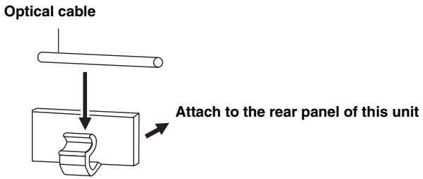
text_image
Optical cable Attach to the rear panel of this unitConnecting the power supply cable
Once all other connections are complete, plug one end of the power supply cable into the AC IN terminal of this unit and then plug the other end into the AC wall outlet.
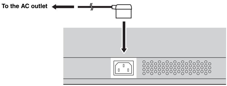
text_image
To the AC outletAbout the RS-232C/REMOTE IN/IR-OUT terminals
The RS-232C, REMOTE IN and IR-OUT terminals do not support normal external component connections. These are control expansion terminals for factory use only.
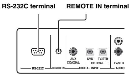
text_image
RS-232C terminal REMOTE IN terminal RS-232C REMOTE IN AUX COAXIAL DVD OPTICAL TV/STB TV/STB DIGITAL INPUT AUDIO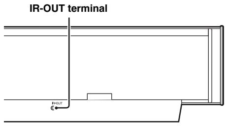
text_image
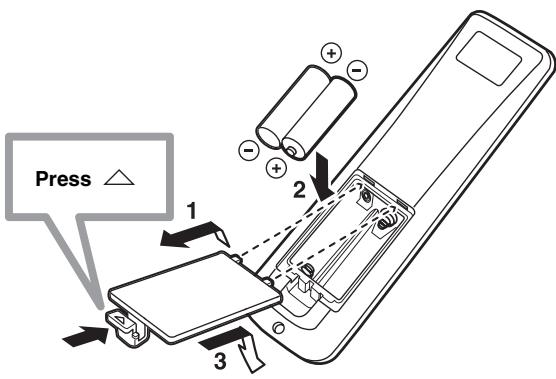
IR-OUT terminal + - OUTInstalling batteries in the remote control
text_image
Press △ 1 2 31 Press and hold the △ mark on the battery cover and then slide off the cover.
2 Insert the two supplied batteries (AA, R6, UM-3) into the battery compartment.
Make sure you insert the batteries according to the polarity markings (+/-).
3 Close the battery cover.
Notes
- Change all of the batteries if you notice the following conditions; the operation range of the remote control decreases, the indicator does not blink or its light becomes dim.
- Do not use old batteries together with new ones.
- Do not use different types of batteries (such as alkaline and manganese batteries) together. Read the packaging carefully as these different types of batteries may have the same shape and color.
- Exhausted batteries may leak. If the batteries have leaked, dispose of them immediately. Avoid touching the leaked material or letting it come into contact with clothing, etc. Clean the battery compartment thoroughly before installing new batteries.
- Do not throw away batteries with general house waste. Dispose of them correctly in accordance with your local regulations.
- The contents of the memory stored in the remote control may be erased in the following cases:
- The remote control is left without batteries for more than 2 minutes.
– Exhausted batteries remain in the remote control. - The buttons on the remote control are accidentally pressed when you change batteries.
- If the memory stored in the remote control is unwantedly erased, insert new batteries and reset the remote control codes again.
Operation range of the remote control
The remote control transmits a directional infrared beam. Use the remote control within 6 m of this unit and point it toward the remote control sensor on this unit during operation.
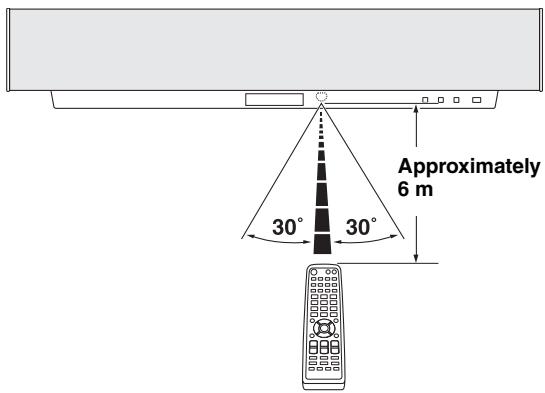
text_image
Approximately 6 m 30° 30°Notes
- Do not spill water or other liquids on the remote control.
- Do not drop the remote control.
- Do not leave or store the remote control in the following types of conditions:
– places of high humidity, such as near a bath - places of high temperatures, such as near a heater or a stove
- places of extremely low temperatures
- dusty places
- Do not expose the remote control sensor on this unit to direct sunlight or lighting such as inverted fluorescent lamps.
- If the batteries grow old, the effective operation distance of the remote control decreases considerably. If this happens, replace the batteries with two new ones as soon as possible.
Using the remote control
The control area and the corresponding functions of the remote control change depending on the currently selected input source. Press the input selector buttons (TV, STB, VCR, DVD or AUX) to select an input source and switch to the operation mode of the corresponding input source. Press YSP to switch to the operation mode of this unit. The buttons on the remote control numbered ③ to ⑨ are operational only after you press YSP to switch to the operation mode of this unit.

You can control other components by setting the appropriate remote control codes (see page 87). Once the remote control code for each input source (TV, STB, VCR, DVD or AUX) is set, see “Controlling other components” on page 88 for further information on the specific functions of the available remote control buttons for each input source. Note that the buttons on the remote control numbered ③ to ⑨ have different functions depending on the currently selected input source.
text_image
DVD VCR STB TV INPUT1 INPUT2 MACRO AUX ● ● INPUTMODE SLEEP YSP 5BEAM ST+3BEAM 3BEAM 1 2 3 STEREO TARGET 4 5 6 MUSIC MOVIE VOL MODE 7 8 9 SPORTS OFF SURROUND 0 +10 CH LEVEL CINEMA DSP MENU ● ● ● ● ● ● ● ● ● ● ● ● ● ● ● ● ● ● ● ● ● ● ● ● ● ● ● ● ● ● ● ● ● ● ● ● ● ● ● ● ● ● ● ● ● ● ● ● ● ● ENTER TEST: RETURN1 Input selector buttons
2 YSP
3 Beam mode buttons
4 Sound field program buttons
5 Cursor buttons △ / ▽ / ◀ / ▷, ENTER
6 VOL MODE
7 SURROUND
8 MENU
9 RETURN
Turning on the power
text_image
INPUT VOLUME STANDBYON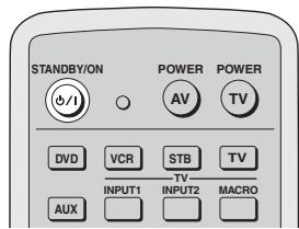
text_image
STANDBY/ON +/-I POWER AV POWER TV DVD VCR STB TV INPUT1 INPUT2 MACRO AUX1 Press STANDBY/ON on the front panel or on the remote control to turn on the power of this unit.

Front panel
or

Remote control
2 Press STANDBY/ON on the front panel or on the remote control again to set this unit to the standby mode.
Note
When the unit is in the standby mode, only STANDBY/ON on the front panel or on the remote control is operational, and the other control buttons on the front panel or on the remote control are not operational until the power of this unit is turned on.
USING SET MENU
Displaying the OSD
This section simply describes how to display the OSD (on-screen display) of this unit on your TV screen and set the parameters for your listening room. Once this is complete, you can enjoy real surround sound while watching TV in the comfort of your own home.
Note
The OSD is not output at the COMPONENT VIDEO OUT jacks of this unit. Connect the VIDEO OUT jack of this unit to the video input jacks of your TV to display the OSD.
1 Check that the video input jack on your TV is connected to the VIDEO OUT jacks of this unit to display the OSD of this unit.
2 Press STANDBY/ON on the front panel or on the remote control to turn on the power of this unit.
Front panel
or

Remote control
3 Turn on the power of your TV.
4 Press TV on the remote control to display the OSD of this unit on your TV screen.
It may take a few seconds before this unit's OSD appears on your TV screen.
If the OSD does not appear, use the remote control provided with your TV to switch the video input until the OSD appears.
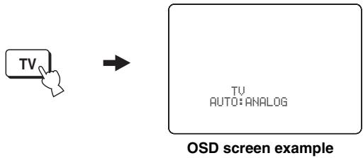
text_image
TV → TV AUTO:ANALOG OSD screen example■ Other buttons that display the OSD
| Remote control buttons that display the OSD | Page |
| 1 Input selector buttons | 39 |
| 2 (●) TruBass | 58 |
| 3 Beam mode buttons | 42 |
| 4 Sound field program buttons | 51 |
| 5 CH LEVEL | 84 |
| 6 VOLUME +/- | 40 |
| 7 MUTE | 41 |
| 8 INPUTMODE | 86 |
| 9 SLEEP | 60 |
| 10 VOL MODE | 56 |
| 11 SURROUND | 46 |
| 12 MENU | 31, 62, 69 |
text_image
DVD VCR STB TV INPUT1 INPUT2 MACRO AUX YSP INPUTMODE SLEEP 5BEAM ST+3BEAM 3BEAM 1 2 3 STEREO TARGET 4 5 6 MUSIC MOVIE VOL MODE 7 8 9 SPORTS OFF SURROUND 0 +10 CH LEVEL CINEMA DSP MENU ENTER TEST RETURN VOLUME CH TV VOL + + + - - - - - - - - - - - - - - - - - - - - - - - - - - - - - - - - - - - - - - - - - - - - - - - - - - - - - - - - - - - - - - - - - - - - - - - - - - - - - - - - - - - -The flow chart of SET MENU
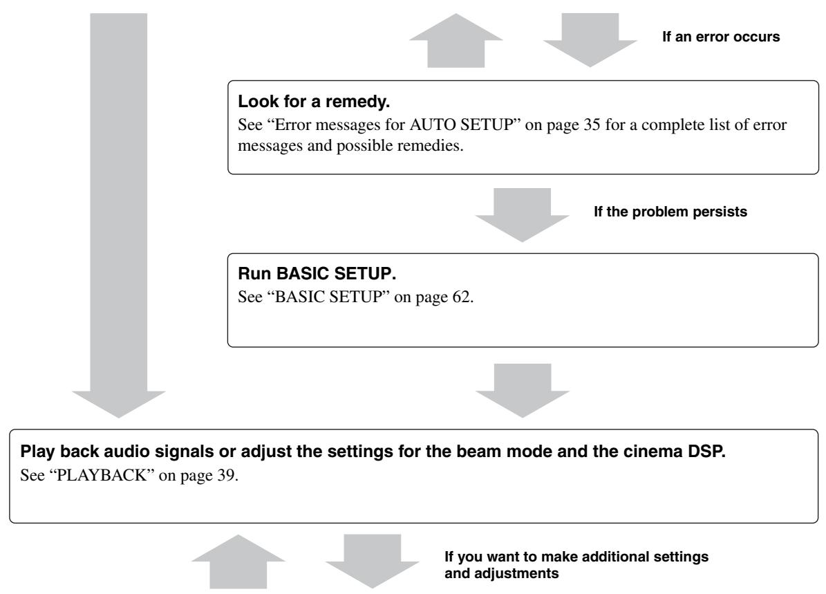
The following diagram illustrates the overall flow of the setup procedure.
Run AUTO SETUP.
See "AUTO SETUP" on page 28.
flowchart
graph TD
A["Look for a remedy.<br>See "Error messages for AUTO SETUP" on page 35 for a complete list of error messages and possible remedies."] --> B["If the problem persists"]
B --> C["Run BASIC SETUP.<br>See "BASIC SETUP" on page 62."]
C --> D["Play back audio signals or adjust the settings for the beam mode and the cinema DSP.<br>See "PLAYBACK" on page 39."]
D --> E["If you want to make additional settings and adjustments"]
E --> F["If an error occurs"]
Run MANUAL SETUP.
See “MANUAL SETUP” on page 68.

- If you cannot clearly hear a sound beam from a specific speaker channel, adjust settings for SETTING PARAMETERS (see page 70) or for BEAM ADJUSTMENT (see page 71) in BEAM MENU.
- If there are acoustically absorbent objects such as curtains in the path of the sound beams, adjust settings for TREBLE GAIN in BEAM MENU (see page 73).
AUTO SETUP
This unit creates a sound field by reflecting sound beams on the walls of your listening room and broadening the cohesion between speaker channels. Just as you would arrange the speaker position of other audio systems, you need to set the beam angle to enjoy the best possible sound from this unit.
This unit employs the beam optimization feature and the YAMAHA Parametric Room Acoustic Optimizer (YPAO) technology with the aid of the supplied optimizer microphone, allowing you to avoid troublesome listening-based speaker setup and achieving highly accurate sound adjustments that best match your listening environment.
The beam optimization is the automated feature of BASIC SETUP, which creates the best possible surround sound field without manually setting the parameters for your listening room.
The YAMAHA Parametric Room Acoustic Optimizer (YPAO) technology performs the following checks and automatically makes appropriate sound adjustments.
DISTANCE:
Checks the phase and the distance of each beam from this unit and adjusts the delay of each channel so that each sound beam reaches the listening position at the same time.
EQUALIZING:
Adjusts frequency and levels of each channel's parametric equalizer to reduce coloration across the channels and create a cohesive sound field. YPAO equalizing calibration incorporates three parameters (frequency, level and Q factor) for each of the seven bands in its parametric equalizer to provide highly precise automatic adjustment of frequency characteristics.
LEVEL:
Checks and adjusts the sound output level of each channel.
The flow chart of AUTO SETUP
This unit performs a series of checks to optimize the beam angle, delay, volume and quality. You can choose to optimize all or part of the parameters.
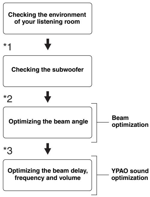
flowchart
graph TD
    A["Checking the environment of your listening room"] --> B["*1"]
    B --> C["Checking the subwoofer"]
    C --> D["*2"]
    D --> E["Optimizing the beam angle"]
    E --> F["*3"]
    F --> G["Optimizing the beam delay, frequency and volume"]
    G --> H["Beam optimization"]
    G --> I["YPAO sound optimization"]
Notes
*1 The subwoofer checking procedure is skipped if BEAM OPTIMZ only is selected.
*2 The beam angle checking procedure is skipped if SOUND OPTIMZ only is selected.
*3 The YPAO sound optimization procedure is skipped if BEAM OPTIMZ only is selected.
Installing the optimizer microphone
The supplied optimizer microphone collects and analyzes the sound that this unit produces in your actual listening environment. Follow the procedure below to connect the optimizer microphone to this unit and make sure that the optimizer microphone is placed in a proper location and that there are no large obstacles between the optimizer microphone and the walls in your listening room.
Notes
- After you have completed the AUTO SETUP procedure, be sure to disconnect the optimizer microphone.
- The optimizer microphone is sensitive to heat.
- Keep it away from direct sunlight.
- Do not place it on top of this unit.
- Do not connect the optimizer microphone to an extension cable as doing so may result in an inaccurate sound optimization.
- An error may occur during the AUTO SETUP procedure if the optimizer microphone is not properly placed in your listening room. To avoid the possibility of an error:
- Do not place the optimizer microphone to the extreme right or left from the center of this unit.
- Do not place the optimizer microphone within 2m from the front of this unit.
- Do not place the optimizer microphone more than 1m from the center height of this unit.
- Make sure that there are no obstacles between the optimizer microphone and the walls in your listening room as these objects obstruct the path of sound beams. However, any objects that are in contact with the walls will be regarded as a protruding part of the walls.
- The best possible results are achieved if the optimizer microphone is placed at the same height as your ears would be when you are seated in your listening position. However, if this is not possible, you can manually fine-tune the sound beam angle and balance the sound beam output levels using MANUAL SETUP (see page 68) once the AUTO SETUP procedure is completed.
- If a subwoofer with adjustable volume and crossover/high cut frequency controls is connected to this unit, set the volume between 11 and 1 o'clock as viewed on a conventional clockface and set the crossover/high cut frequency to the maximum.
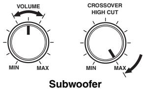
text_image
VOLUME MIN MAX CROSSOVER HIGH CUT MIN MAX Subwoofer1 Press STANDBY/ON on the front panel or on the remote control to turn off the power of this unit.
Front panel
or

Remote control
2 Connect the supplied optimizer microphone to the OPTIMIZER MIC jack on the side of this unit.
Side view
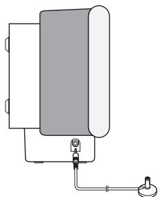
natural_image
Pure diagram of a vertical pipe system with a valve and base, no text or symbols presentOptimizer microphone
3 Place the optimizer microphone on a flat level surface more than 2 m from the front of the unit and within 1 m from the center height of the unit with the optimizer microphone head upward at your normal listening position.
Note
Be sure to place the optimizer microphone on an imaginary center line drawn from this unit.

You may want to use a tripod or the supplied cardboard microphone stand to affix the optimizer microphone at the same height as your ears would be when you are seated in your listening position.
Example of using a tripod
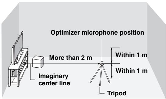
text_image
Optimizer microphone position More than 2 m Within 1 m Within 1 m Imaginary center line TripodExample of using the supplied cardboard microphone stand
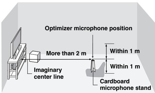
text_image
Optimizer microphone position More than 2 m Within 1 m Imaginary center line Within 1 m Cardboard microphone stand■ Assembling the supplied cardboard microphone stand
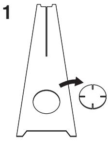
You will find three separate parts (one circular-shaped part and two longitudinal-shaped parts) of the cardboard microphone stand originally put together.
natural_image
Simple line drawing of a triangular container with internal circular holes and an arrow pointing to a circular feature (no text or symbols)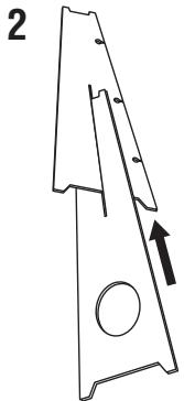
natural_image
Technical line drawing of a mechanical part with an arrow indicating direction (no text or symbols)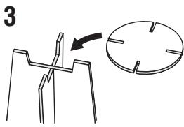
text_image
3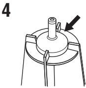
natural_image
Mechanical component diagram showing a cylindrical shaft mounted on a circular base with a pointed end, labeled with number 4 (no text or symbols on the diagram itself)1 Disassemble the three parts of the cardboard microphone stand originally put together.
2 Insert one of the longitudinal-shaped part into the crevice of the other longitudinal-shaped part.
3 Place the circular-shaped part on top of the two combined longitudinal-shaped parts.
4 Place the supplied optimizer microphone on top of the circular-shaped part.
Using AUTO SETUP
Once the optimizer microphone is firmly connected to this unit and properly placed in your listening room, follow the procedure below to start the AUTO SETUP procedure.
text_image
INPUT VOLUME STANDBY/ON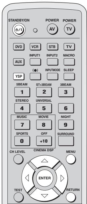
text_image
STANDBY/ON POWER POWER AV TV DVD VCR STB TV INPUT1 INPUT2 MACRO AUX (●) INPUTMODE SLEEP YSP 5BEAM ST+3BEAM 3BEAM 1 2 3 STEREO UNIVERSAL 4 5 6 MUSIC MOVIE NIGHT 7 8 9 SPORTS OFF SURROUND 0 +10 CH LEVEL CINEMA DSP MENU ENTER TEST RETURNNotes
- If your listening room has curtains, open the curtains before starting the BEAM OPT+SOUND OPTIMZ or the BEAM OPTIMZ only procedure.
- Make sure that your listening room is as quiet as possible while this unit is performing the AUTO SETUP procedure.
- Once the AUTO SETUP procedure has started, position yourself beside or behind this unit so that you may not obstruct the path of sound beams. To achieve the best results possible, however, it is strongly recommended that you should evacuate yourself from your listening room until the AUTO SETUP procedure is completed.
- Be advised that it is normal for loud test tones to be output during the AUTO SETUP procedure.
- The AUTO SETUP procedure may not be run successfully if this unit is installed in one of the rooms described in “Before installing this unit” on page 11. In such cases, run BASIC SETUP (see page 62) or MANUAL SETUP (see page 68) to manually adjust the corresponding parameters.
- If the AUTO SETUP procedure stops and an error message appears on the screen, see “Error messages for AUTO SETUP” on page 35 for appropriate remedies.
#
You can save the settings optimized by the AUTO SETUP procedure (see page 36). A set of settings optimized according to specific conditions of your listening environment can be recalled later depending on the varying conditions of your listening environment (see page 37).
1 Press STANDBY/ON on the front panel or on the remote control to turn on the power of this unit.
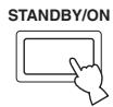
Front panel
or

Remote control
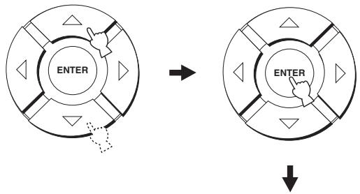
2 Press YSP on the remote control to switch to the operation mode of this unit.

3 Press MENU on the remote control.
The SET MENU screen appears on your TV.
MENU


SET MENU
→ · MEMORY
• AUTO SETUP
-BASIC SETUP
- MANUAL SETUP
[△]/[▽]:Up/Down
#
- The control buttons used for SET MENU are displayed on the bottom of the screen.
- To return to the previous screen while using SET MENU, press RETURN on the remote control.
- To resume cursor button operations after changing the control area by pressing an input selector button, press TEST on the remote control.
- To cancel the SET MENU screen, press MENU once more.
- You can also perform the following operations in the front panel display.
- If you press an input selector button during the SET MENU operations, the cursor buttons become ineffective. In this case, press TEST once.
4 Press △ / ▽ on the remote control to select AUTO SETUP and then press ENTER.
The following screen appears on your TV.
flowchart
graph TD
    A["ENTER"] --> B["→"]
    B --> C["ENTER"]
    C --> D["↓"]
- AUTO SETUP
→ BEAM+SOUND OPTIMZ BEAM OPTIMZ only SOUND OPTIMZ only
[▲]/[▼]:Up/Down
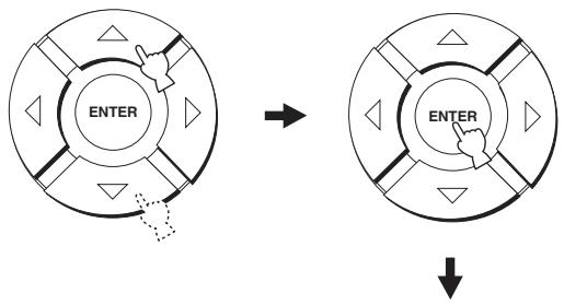
5 Press △ / ▽ to select BEAM OPT+SOUND OPTIMZ, BEAM OPTIMZ only or SOUND OPTIMZ only and then press ENTER.
The following screen appears on your TV.
flowchart
graph TD
    A["ENTER"] --> B["Arrow"]
    B --> C["ENTER"]
    C --> D["Down Arrow"]
PREPARATION
→ INSTALLING··Parallel to Wall MOUNTING···SHELF REFLECTING··NORMAL
Set MIC in front of YSP MIN 2m/6.5ft
[▲]/[▼]:Up/Down/[■]/[■]:Sel
BEAM OPT+SOUND OPTIMZ
(Beam optimization and YPAO sound optimization)
Use to optimize the beam angle, delay, volume and quality so that the parameters best match your listening environment. It takes about three minutes.
It is recommended that you should select this optimization feature in the following cases:
• If you make settings for the first time.
• If the unit has been relocated.
- If your listening room has been restructured.
- If the objects in your listening room (furniture, etc.) have been rearranged.
BEAM OPTIMZ only
(Beam optimization only)
Use to optimize the beam angle so that the parameter best matches your listening environment. It takes about a minute.
SOUND OPTIMZ only
(YPAO sound optimization only)
Use to optimize the beam delay, volume and quality so that the parameters best match your listening environment. It takes about two minutes.
It is recommended that you should select this optimization feature in the following cases:
- If you have opened or closed the curtains in your listening room before using this unit.
• If you have manually set the beam angle.
Note
You must optimize the beam angle in the BEAM OPTIMZ only procedure before starting the SOUND OPTIMZ only procedure.
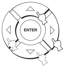
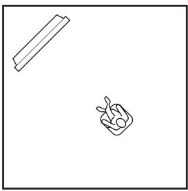
6 Press △ / ▽ / ◀ / ◇ to select and configure each parameter and then press ENTER.
flowchart
graph TD
    A["ENTER"] --> B["Process Step 1"]
    B --> C["Process Step 2"]
    C --> D["Process Step 3"]
    D --> E["Process Step 4"]
    E --> F["Process Step 5"]
    F --> G["Process Step 6"]
    G --> H["Process Step 7"]
    H --> I["Process Step 8"]
    I --> J["Process Step 9"]
    J --> K["Process Step 10"]
INSTALLING (Installing)
Use to select the installed position of the unit in your listening room.
Choices: Parallel to Wall (Parallel with wall installation), Angle to Wall or corner (Corner installation)
Angle to Wall or corner
natural_image
Simple line drawing of a pencil and a hand gesture (no text or symbols)Parallel to Wall
natural_image
Simple line drawing of a tray and a small container with a carrot (no text or symbols)- Select Angle to Wall or corner if the unit is installed in the corner. The beam mode is set to ST+3BEAM (see page 43).
- Select Parallel to Wall if the unit is installed in parallel with the wall. The beam mode is set to 5BEAM (see page 43).
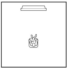
MOUNTING (Mounting)
Use to select the mounted position of the unit in your listening room.
Choices: SHELF (Shelf mount), WALL (Wall mount)
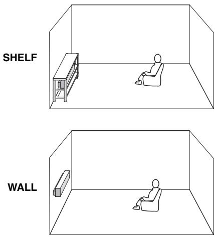
- Select WALL if the unit is mounted on the wall.
- Select SHELF if the unit is mounted on the shelf.
REFLECTING (Reflecting)
Use to select the reflectivity of your listening room.
Choices: NORMAL (Normal), HI ECHO (High echo)
- Select NORMAL if your listening room has a normal reflectivity.
- Select HI ECHO if your listening room has highly reflective surfaces such as concrete walls.
7 Check the following points once again before starting the AUTO SETUP procedure.
- Is the optimizer microphone firmly connected to this unit?
- Is the optimizer microphone placed in a proper location?
- Are there any large obstacles in between the optimizer microphone and the walls in your listening room?
8 Press ENTER to start the AUTO SETUP procedure.
The following screen appears on your TV. ENVIRONMENT CHECK (Environmental noise check), SUB WOOFER CHECK (Subwoofer check) and WILL START in 10 SEC (Will start in 10 sec) are displayed in order as the PREPARATION procedure is in progress.
text_image
ENTERPREPARATION
→ ENVIRONMENT CHECK
...[OK]
SUB WOOFER CHECK
...[NOT IN USE]
WILL START in 10 SEC
Move aside or behind YSP
*****
PREPARATION
→ ENVIRONMENT CHECK
... [OK]
WILL START in 10 SEC
Move aside or behind YSP
*****
If you selected BEAM OPT+SOUND OPTIMZ or SOUND OPTIMZ only in step 5.
If you selected BEAM OPTIMZ only in step 5.


AUTO BEAM OPTIMIZATION
AUTO BEAM MEASUREMENT/SET
Skipped if you selected SOUND OPTIMZ only in step 5.

ACQUSTIC OPTIMIZATION
→ SETTING VOLUME
MEASURE DISTANCE
MEASURE FREQ CHAR
MEASURE VOLUME
Skipped if you selected BEAM OPTIMZ only in step 5.
If an error occurs, an error message is displayed. See “Error messages for AUTO SETUP” on page 35 for a complete list of error messages and their proper remedies. Follow the instructions and press RETURN to perform the AUTO SETUP procedure again.
9 Check that the following screen is displayed on your TV.
The results of the AUTO SETUP procedure are displayed on your TV.
Example of the SHOW RESULT screen
SHOW RESULT
BEAM MODE: 5BEAM
SUBWOOFER: NOT APPLICABLE
If you selected BEAM OPT+SOUND OPTIMZ or SOUND OPTIMZ only in step 5.
SHOW RESULT
BEAM MODE: 5BEAM
If you selected BEAM OPTIMZ only in step 5.
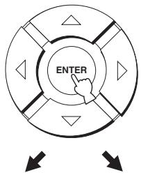
10 Press ENTER to confirm the results or press RETURN to cancel the results.
The following screen is displayed temporarily for a few seconds and then disappear from your TV.
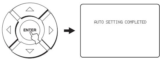
flowchart
graph LR
    A["ENTER"] --> B["AUTO SETTING COMPLETED"]
Error messages for AUTO SETUP
Before the AUTO SETUP procedure starts
| Error message | Cause | Remedy | See page |
| ERROR E-2No MIC Detected. Please checkMIC connection and re-try. | The optimizer microphone is not connected to this unit. | Connect the optimizer microphone to this unit. | 29 |
While the AUTO SETUP procedure is in progress-
| Error message | Cause | Remedy | See page |
| ERROR E-1Please test in more quiet environment. | There is too much unwanted noise in your listening room. | Make sure that your listening room is as quiet as possible. You may want to choose certain hours during the day when there is not much noise coming from outside. | — |
| ERROR E-2No MIC detected. Please check MIC connection and re-try. | The optimizer microphone was disconnected while the AUTO SETUP procedure was in progress. | Make sure that the optimizer microphone is firmly connected to this unit. | 29 |
| ERROR E-3Unexpected control is detected.Please re-try. | Some other operations were performed on this unit while the AUTO SETUP procedure was in progress. | Do not perform any other operations while the AUTO SETUP procedure is in progress. | — |
| ERROR E-4Please check MIC position. MIC should be set in front of YSP. | The optimizer microphone is not placed in front of this unit. | Make sure that the optimizer microphone is installed in front of this unit. | 29 |
| ERROR E-5Please check MIC position. MIC should be set above 2m/6.5ft. | The optimizer microphone is not placed in the right distance from this unit. | Make sure that the optimizer microphone is installed more than 2 m from the front of this unit and within 1 m from the center height of this unit. | 29 |
| ERROR E-6Volume level is smaller than expected. Please check MIC position/connection and re-try. | The optimizer microphone cannot collect the sound produced by this unit because the sound output level is too low. | Make sure that the optimizer microphone is firmly connected to this unit and placed in a proper location. If the problem persists, contact the nearest YAMAHA service center for assistance. | 29 |
| ERROR E-7Unexpected Error Happened.Please re-try. | An internal system error occurred. | Repeat the AUTO SETUP procedure. | — |
USING THE SYSTEM MEMORY
Saving settings
You can save the current settings adjusted in SET MENU in the system memory of this unit. It is handy to save certain settings according to the varying conditions of your listening environment. For example, if there are curtains in the path of beams, the effectiveness of the beams will vary depending on whether the curtains are open or closed.
When the curtains are open
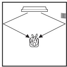
flowchart
graph TD
    A["Start"] --> B{Decision}
    B --> C["Output Box"]
    B --> D["End"]
When the curtains are closed
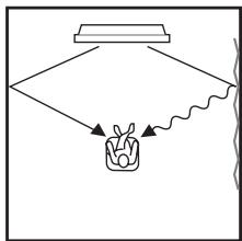
flowchart
graph TD
    A["Top Box"] --> B["Container"]
    B --> C["Wavy Line"]
    C --> D["End"]
1 Press YSP on the remote control to switch to the operation mode of this unit.

2 Press MENU on the remote control.
The SET MENU screen appears on your TV.


SET MENU
→ · MEMORY
• AUTO SETUP
-BASIC SETUP
- MANUAL SETUP
[血]/[甲]:Up/Down

- The control buttons used for SET MENU are displayed on the bottom of the screen.
- To return to the previous screen while using SET MENU, press RETURN on the remote control.
- To resume cursor button operations after changing the control area by pressing an input selector button, press TEST on the remote control.
- To cancel the SET MENU screen, press MENU once more.
- You can also perform the following operations in the front panel display.
- If you press an input selector button during the SET MENU operations, the cursor buttons become ineffective. In this case, press TEST once.
3 Press △ / ▽ to select MEMORY and then press ENTER.
The following screen appears on your TV.

flowchart
graph TD
    A["ENTER"] --> B["ENTER"]
    B --> C["MEMORY\n1)LOAD\n2)SAVE\n[▲"]/[▼]:Up/Down\n["ENTER"]:Enter]
4 Press △ / ▽ to select SAVE and then press ENTER.
The following screen appears on your TV.
flowchart
graph TD
    A["ENTER"] --> B["ENTER"]
    B --> C["2) MEMORY SAVE\n▶ USER1  USER2  USER3\n[◀"]/[◀]:Select\n["ENTER"]:Enter]
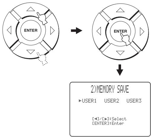
5 Press ◀ / ▶ to select USER1, USER2 or USER3 and then press ENTER.
The following screen appears on your TV.
flowchart
graph TD
A["ENTER"] --> B["ENTER"]
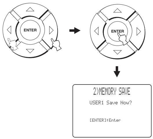
B --> C["2) MEMORY SAVE<br>USER1 Save Now?"]
C --> D["[ENTER"]: Enter]
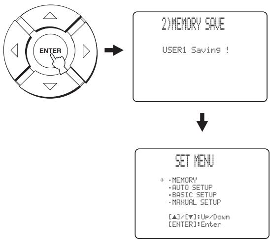
6 Press ENTER again.
The new parameters are saved as USER1, USER2 or USER3. Once the parameters are saved, the display returns to the SET MENU screen.
flowchart
graph TD
    A["ENTER"] --> B["2) MEMORY SAVE<br>USER1 Saving!"]
    B --> C["SET MENU<br>→: MEMORY<br>• AUTO SETUP<br>• BASIC SETUP<br>• MANUAL SETUP<br>[▲"]/[▼]:Up/Down
[ENTER]:Enter]
7 Press MENU to exit.
The SET MENU screen disappears from your TV.

Loading settings
You can recall the settings saved in “Saving settings” on page 36 according to the varying conditions of your listening environment.
1 Press YSP on the remote control to switch to the operation mode of this unit.

2 Press MENU on the remote control.
The SET MENU screen appears on your TV.

text_image
MENU SET MENU → • MEMORY • AUTO SETUP • BASIC SETUP • MANUAL SETUP [▲]/[▼]:Up/Down [ENTER]:Enter
- The control buttons used for SET MENU are displayed on the bottom of the screen.
- To return to the previous screen while using SET MENU, press RETURN on the remote control.
- To resume cursor button operations after changing the control area by pressing an input selector button, press TEST on the remote control.
- To cancel the SET MENU screen, press MENU once more.
- You can also perform the following operations in the front panel display.
- If you press an input selector button during the SET MENU operations, the cursor buttons become ineffective. In this case, press TEST once.
3 Press △ / ▽ to select MEMORY and then press ENTER.
The following screen appears on your TV.
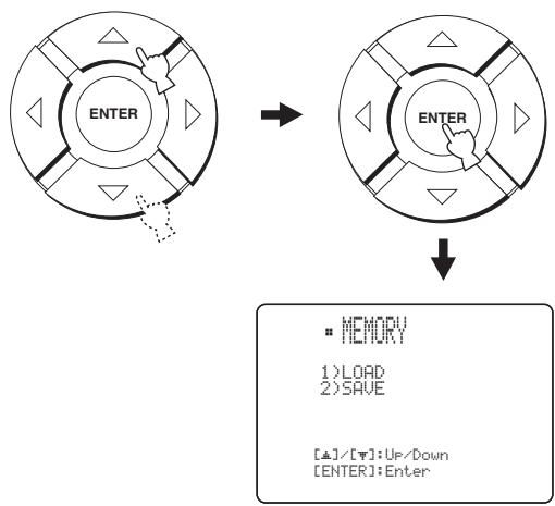
flowchart
graph TD
    A["ENTER"] --> B["ENTER"]
    B --> C["MEMORY\n1) LOAD\n2) SAVE\n[▲"]/[▼]: UP/Down\n["ENTER"]: Enter]
4 Press / to select LOAD and then press ENTER.
The following screen appears on your TV.

flowchart
graph TD
    A["ENTER"] --> B["ENTER"]
    B --> C["1) MEMORY LOAD\n▶ USER1  USER2  USER3\n[◀"]/[◀]:Select]
5 Press ◀ / ▶ to select USER1, USER2 or USER3 and then press ENTER.
The following screen appears on your TV.
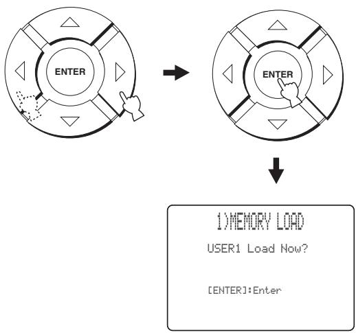
flowchart
graph TD
    A["Device 1"] --> B["Device 2"]
    B --> C["↓"]
    C --> D["1) MEMORY LOAD\nUSER1 Load Now?\n[ENTER"]: Enter]
6 Press ENTER again.
The new parameters are saved as USER1, USER2 or USER3. Once the parameters are saved, the display returns to the SET MENU screen.
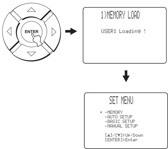
flowchart
graph TD
    A["ENTER"] --> B["1) MEMORY LOAD\nUSER1 Loading!"]
    B --> C["SET MENU\n→: MEMORY\n• AUTO SETUP\n• BASIC SETUP\n• MANUAL SETUP\n[▲"]/[▼]: Up/Down\n["ENTER"]: Enter]
7 Press MENU to exit.
The SET MENU screen disappears from your TV.

PLAYBACK
Selecting the input source
You can play back sound from the components connected to this unit simply by pressing INPUT on the front panel repeatedly or pressing one of the input selector buttons (TV, STB, VCR, DVD or AUX) on the remote control. The name of the selected input source and the type of the corresponding input mode appear in the front panel display.
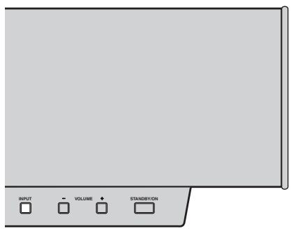
text_image
INPUT VOLUME STANDBY/ON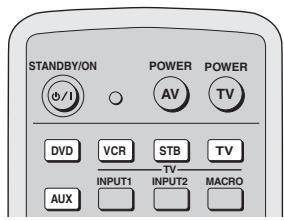
text_image
STANDBY/ON d/i POWER AV TV DVD VCR STB TV INPUT1 TV INPUT2 MACRO AUX■ Front panel operations
Press INPUT on the front panel repeatedly to toggle between TV, STB, DVD, VCR and AUX.
The name of the corresponding input source and the type of the current input mode are shown in the front panel display.
■ Remote control operations
Press TV on the remote control to play back a TV program.
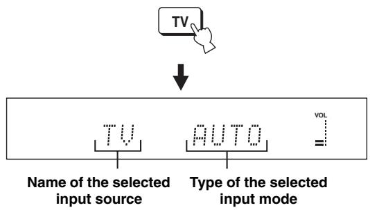
flowchart
graph TD
    A["TV"] --> B["↓"]
    B --> C["TV"]
    B --> D["AUTO"]
    B --> E["VOL"]
    style C fill:#f9f,stroke:#333
    style D fill:#f9f,stroke:#333
    style E fill:#ccf,stroke:#333
Press STB on the remote control to play back a satellite broadcast.
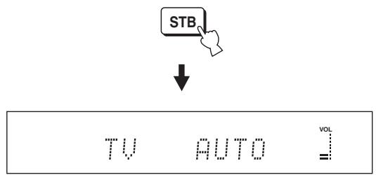
text_image
STB ↓ TV AUTO VOL =Press DVD on the remote control to play back a DVD.
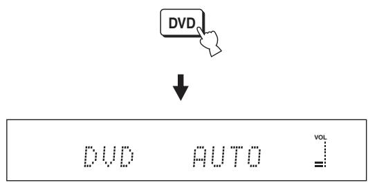
text_image
DVD ↓ DVD AUTO VOL =Press VCR on the remote control to play back a video tape.
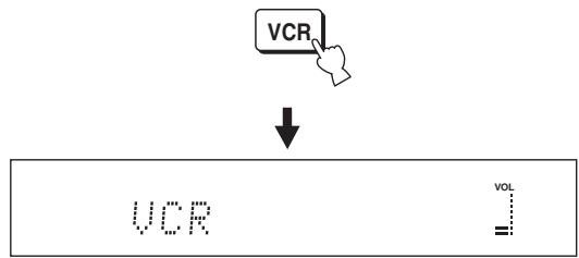
flowchart
graph TD
    A["VCR"] --> B["↓"]
    B --> C["VOL"]
Press AUX on the remote control to play back a component connected to the AUX jack on the rear panel of this unit.
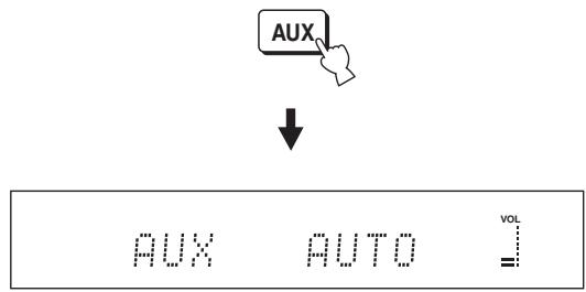
text_image
AUX ↓ AUX AUTO VOL =Playing back sources
Once an input source is selected (see page 39), you can play back the selected input source.
Note
This section uses a DVD player as an example of the playback source.

For details on the TV and the DVD player you are using, refer to the owner's manual supplied with the TV and the DVD player.
1 Turn on the power of your DVD player using the remote control supplied with the DVD player.
2 Switch to the video input on your TV using the remote control supplied with the TV so that the DVD menu screen is displayed.
3 If necessary, turn down the volume of your TV until you cannot hear any sound.
4 Press DVD on the remote control to select DVD as the input source.

5 Play back the DVD on your DVD player using the supplied remote control.
Audio signals from your DVD player are output from the speakers of this unit.

- If the output volume is too low, increase the volume on this unit to around -25 dB.
- If you have set the appropriate remote control codes for your TV and DVD player, you can use the remote control supplied with this unit to operate these components. For details on how to set remote control codes, see page 87.
Adjusting the volume
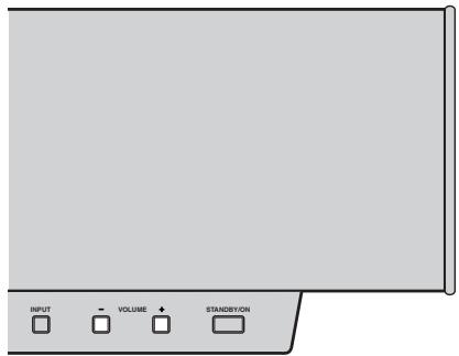
text_image
INPUT VOLUME STANDBYON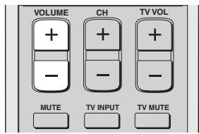
text_image
VOLUME + - CH + - TV VOL + - MUTE TV INPUT TV MUTEPress VOLUME +/- on the front panel or on the remote control to increase or decrease the volume level.
The numeric value of the volume level appears in the front panel display.
Control range: 0.0 dB to -99.5 dB, MIN (minimum)
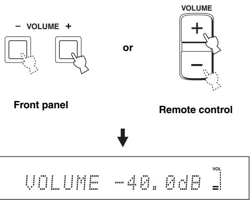
text_image
- VOLUME + Front panel or VOLUME + - Remote control ↓ VOLUME -40.6dB VOL =VOLUME MUTE appears at the minimum volume level.
VOLUME MIN
Notes
- The volume level of all input sources (including multi-channel as well as stereo sources) changes at the same time.
- 0.5 dB of the volume level increases or decreases each time you press VOLUME +/-.
- You can continuously increase or decrease the volume level if you press and hold VOLUME +/-.
Muting the sound
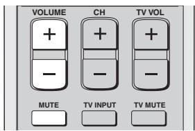
text_image
VOLUME + - CH + - TV VOL MUTE TV INPUT TV MUTE1 Press MUTE on the remote control to mute the sound.
AUDIO MUTE ON appears in the front panel display, and the volume level indicator flashes.
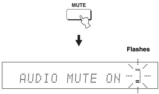
flowchart
graph TD
    A["MUTE"] --> B["↓"]
    B --> C["Flashes"]
    C --> D["AUDIO MUTE ON ... = ..."]
    style D fill:#f9f,stroke:#333
2 Press MUTE on the remote control again (or press VOLUME +/-) to resume the sound output.
AUDIO MUTE OFF appears temporarily in the front panel display (or the numeric value of the current volume level appears if you press VOLUME +/-), and the volume level indicator lights up.
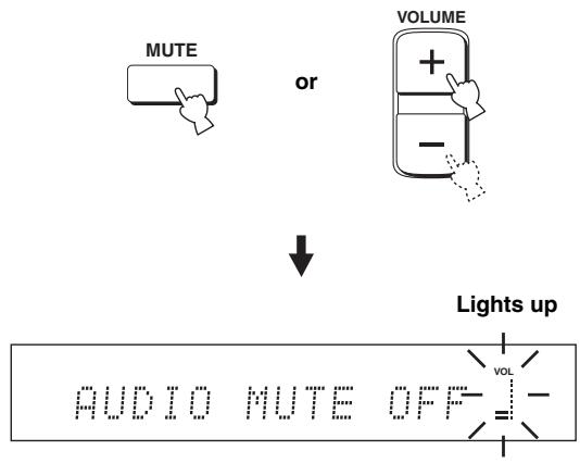
text_image
MUTE or VOLUME + - ↓ Lights up AUDIO MUTE OFF VOL -Note
The sound output of all input sources (including multi-channel as well as stereo sources) is muted at the same time.

You can select whether the sound output is to be muted completely or by 20 dB when you press MUTE (see page 76).
BEAM MODE
You can change the beam mode to suit the input source of this unit using the beam mode buttons on the remote control (STEREO, 3BEAM, 5BEAM, ST+3BEAM or TARGET). Select stereo mode for 2-channel sources, 3 beam mode, 5 beam mode and stereo plus 3 beam mode for 5.1-channel playback.
All the beam modes are available in the following cases:
- If you selected Parallel to Wall for INSTALLING in AUTO SETUP (see page 33)
- If you selected settings other than CORNER RIGHT or CORNER LEFT for INSTALLED POSITION in BASIC SETUP (see page 64)
- If you selected FLAT TO WALL for INSTALLED POSITION in MANUAL SETUP (see page 70)
Only stereo, stereo plus 3 beam and target modes are available in the following cases:
- If you selected Angle to Wall or corner for INSTALLING in AUTO SETUP (see page 33)
- If you selected CORNER RIGHT or CORNER LEFT for INSTALLED POSITION in BASIC SETUP (see page 64)
- If you selected ANGLE TO WALL OR CORNER for INSTALLED POSITION in MANUAL SETUP (see page 70)
| Beam mode | AUTO SETUP | BASIC SETUP | MANUAL SETUP | |||
| INSTALLING(see page 33) | INSTALLED POSITION(see page 64) | INSTALLED POSITION(see page 70) | ||||
| Parallel to Wall | Angle to Wall or corner | CORNER RIGHT or CORNER LEFT | Other settings | FLAT TO WALL | ANGLE TO WALL OR CORNER | |
| STEREO | Yes | Yes | Yes | Yes | Yes | Yes |
| 3BEAM | Yes | No | No | Yes | Yes | No |
| 5BEAM | Yes | No | No | Yes | Yes | No |
| ST+3BEAM | Yes | Yes | Yes | Yes | Yes | Yes |
| TARGET | Yes | Yes | Yes | Yes | Yes | Yes |
Note
Yes: the corresponding beam mode is available.
No: the corresponding beam mode is not available.
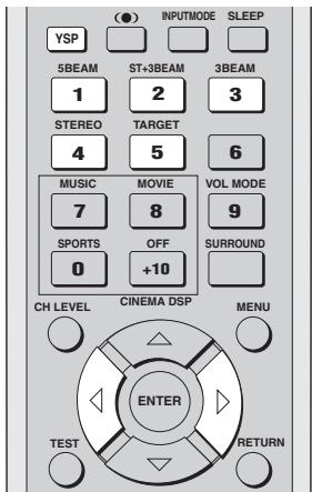
text_image
(●) INPUTMODE SLEEP YSP 5BEAM ST+3BEAM 3BEAM 1 2 3 STEREO TARGET 4 5 6 MUSIC MOVIE VOL MODE 7 8 9 SPORTS OFF SURROUND 0 +10 CH LEVEL CINEMA DSP MENU ENTER TEST RETURN1 Press YSP on the remote control to switch to the operation mode of this unit.

2 Press one of the beam mode buttons to select the desired beam mode.
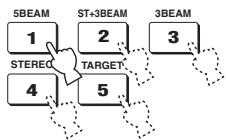
flowchart
graph TD
    A["1"] --> B["STEREO"]
    C["2"] --> D["TARGET"]
    E["3"] --> F["3BEAM"]
5 beam mode
Outputs sound beams from the front left and right, center, and surround left and right speakers. This mode is ideal for enjoying surround sound effects to the fullest when watching DVDs recorded in a multi-channel format or playing back 2-channel sources in a multi-channel format.
Press 5BEAM on the remote control to select the 5 beam mode.

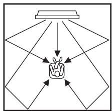
flowchart
graph TD
    A["Central Object"] --> B["Light Source"]
    A --> C["Light Source"]
    A --> D["Light Source"]
    A --> E["Light Source"]
    A --> F["Light Source"]
    A --> G["Light Source"]
Notes
- To achieve the best surround sound effect, make sure that there are no obstacles placed in the path of sound beams in that the objects may prevent the beams from rebounding directly off the walls in your listening room.
- The front left and right sound beams are output towards the walls in your listening room.
Stereo plus 3 beam mode
Outputs sound beams from the front left and right, center, and surround left and right speakers. This mode is ideal for watching live recordings on a DVD. Vocals and instrumental sounds can be heard close to the center of the listening position while sound reflections from the venue itself can be heard on your right and left, giving you the feeling that you are sitting right in front of the stage.
Press ST+3BEAM on the remote control to select the stereo plus 3 beam mode.

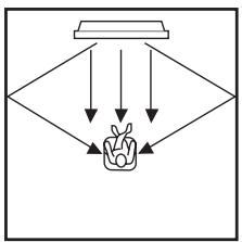
flowchart
graph TD
    A["Input 1"] --> C["Output"]
    B["Input 2"] --> C
    D["Input 3"] --> C
    E["Input 4"] --> C
    F["Input 5"] --> C
    C --> G["Final Output"]
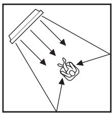
natural_image
Simple line drawing of a funnel with arrows indicating light or motion, and a hand pointing at it (no text or symbols)Note
The front left and right sound beams are output directly to the listening position.
3 beam mode
Outputs sound beams from the front left and right and center speakers. This mode is ideal for enjoying movies with the whole family. Because the listening position area is widened, you can enjoy excellent quality surround sound over a wider area.
Press 3BEAM on the remote control to select the 3 beam mode.
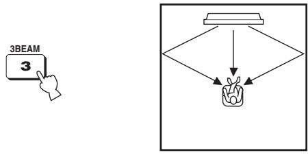
flowchart
graph TD
    A["Hand Clicking 3BEAM"] --> B{Decision}
    B --> C["Plant"]
    C --> D["Output"]

You can achieve a more realistic surround effect if you adjust settings for IMAGE LOCATION in BEAM MENU (see page 74).
Notes
- When you play back multi-channel sources, surround left and right signals are mixed down and output from the front left and right speakers.
- The front left and right sound beams are output towards the walls in your listening room.
Stereo mode
Outputs sound beams from the front left and right speakers in the 2-channel stereo mode. This mode is ideal for playing back hi-fi sources, such as CDs, and can be used to replace your TV speakers.
Press STEREO on the remote control to select the stereo mode.
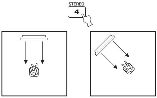
flowchart
graph TD
    A["STEREO 4"] --> B["Plant"]
    B --> C["Tray Box"]
    style A fill:#f9f,stroke:#333
    style B fill:#ccf,stroke:#333
    style C fill:#cfc,stroke:#333
Notes
- When you play back multi-channel sources, all signals except those for the front left and right speakers are mixed down and output from the front left and right speakers. No audio is output from the center and rear channels.
- The surround mode becomes disabled when the stereo mode is selected.
- When you play back Dolby Digital audio signals in the stereo mode, the dynamic range becomes compressed. If the volume level decreases to the extreme, use other beam modes except the target mode.
- If the stereo mode is selected as the beam mode, the surround modes (see page 46) and the CINEMA DSP programs (see page 51) become ineffective.
Target mode
Outputs sound beams in a single channel. This mode is ideal if you do not want the sound beams to be reflected on the walls in your listening room or if you do not disturb others asleep while enjoying music or movies at night.
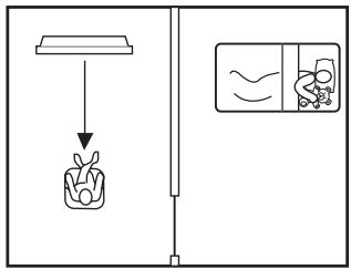
text_image
Diagram showing a kitchen utensil dropping into a container with a side-view view of food being processed.In addition, you can adjust the horizontal angle of the sound beams so that you can hear dialogues clearly even from a distant location such as the kitchen area in your listening room.
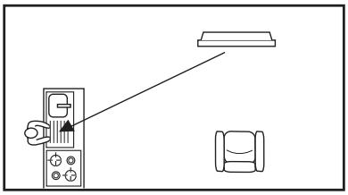
natural_image
Diagram showing a hand operating a control panel with an arrow pointing to a light fixture (no text or symbols present)Press TARGET on the remote control to select the target mode and then press ◀ / ▷ to adjust the angle.
Control range: L90° to R90°
- Press ◀ repeatedly to increase the horizontal angle on the left side.
- Press repeatedly to increase the horizontal angle on the right side.
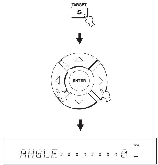
- The sound beams are not rebounded off the walls in your listening room.
- If the target mode is selected as the beam mode, the surround modes (see page 46), the CINEMA DSP programs (see page 51) and the TruBass (see page 58) become ineffective. In addition, no audio is output from the subwoofer connected to this unit.
Depending on the input source and the selected surround mode, the indicators in the front panel display light up as follows:
| Status | Indicator |
| When PCM signals are being input | PCM |
| When DTS digital signals are being input or when DTS Neo:6 is selected | dts |
| When Dolby Digital signals are being input | DIGITAL |
| When Dolby Pro Logic is selected | PL |
| When Dolby Pro Logic II is selected | PLII |

- You can select an input mode (AUTO, DTS or ANALOG) by pressing INPUTMODE on the remote control repeatedly (see page 86).
- Discs encoded in DTS-ES or Dolby Digital 5.1 EX will be played back in DTS or Dolby Digital.
■ Surround modes and recommended sources
| Surround mode | Recommended source | |
| Dolby Pro Logic | - | All sources |
| Dolby Pro Logic II | Movie | Movies |
| Music | Music | |
| Game | Games | |
| DTS Neo:6 | Cinema | Movies |
| Music | Music | |
Notes
- Surround modes are available when the beam mode is set to a setting other than the stereo or the target mode.
- When you select an input source (see page 39), the surround mode used for the previously selected input source is selected.
- If the power of this unit is turned off and on again, the surround mode used for the previously selected input source before the power was turned off is selected.
- The surround modes are available only when the CINEMA DSP programs are turned off (see page 55) or when the movie program is selected as the CINEMA DSP program (see page 54).
- Only Dolby Pro Logic, Dolby Pro Logic II Movie and DTS Neo:6 Cinema are available when the movie program is selected as the CINEMA DSP program (see page 54).
- If the surround modes are not available, “Prohibit” appears in the front panel display when you press SURROUND on the remote control.
- The surround modes are available only when 2-channel signals are being input. If you try to switch between the surround modes when 5.1 channel signals are being input, “Prohibit” appears in the front panel display.
Enjoying 2-channel sources in surround sound
This unit can decode 2-channel sources for 5.1 channel playback so that you can enjoy a variety of surround sound effects by switching the surround mode.

The surround modes are available only when the CINEMA DSP programs are turned off (see page 55) or when the movie program is selected as the CINEMA DSP program (see page 54). In addition, the beam mode must be set to the 5 beam mode, the stereo plus 3 beam mode or the 3 beam mode (see page 42).
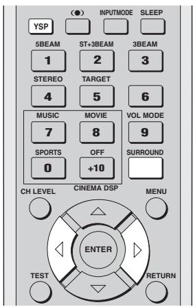
text_image
(●) INPUTMODE SLEEP YSP 5BEAM ST+3BEAM 3BEAM 1 2 3 STEREO TARGET 4 5 6 MUSIC MOVIE VOL MODE 7 8 9 SPORTS OFF SURROUND 0 +10 CH LEVEL CINEMA DSP MENU ENTER TEST RETURN1 Press YSP on the remote control to switch to the operation mode of this unit.

2 Press SURROUND on the remote control repeatedly (or press SURROUND and then press ◀/▷) to switch between surround modes.
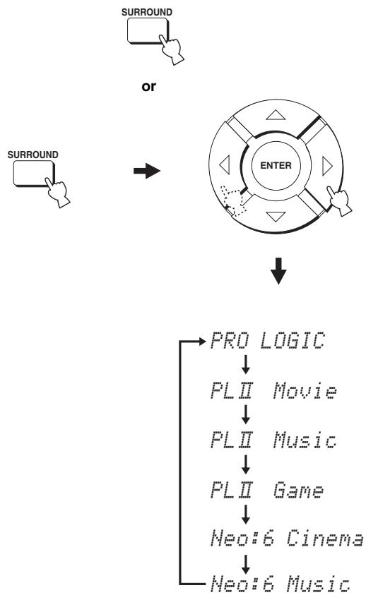
flowchart
graph TD
    A["SURROUND"] --> B["ENTER"]
    C["SURROUND"] --> B
    B --> D["PRO LOGIC"]
    D --> E["PLII Movie"]
    E --> F["PLII Music"]
    F --> G["PLII Game"]
    G --> H["Neo:6 Cinema"]
    H --> I["Neo:6 Music"]
Example of the surround mode display in the front panel display when the CINEMA DSP program is turned off
Enjoying TV in surround sound
You can enjoy analog audio signals output from your TV in real surround sound.

Before performing the steps below, set the volume of this unit to -40 dB. If necessary, adjust the volume level in step 4 below.
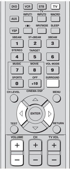
text_image
DVD VCR STB TV INPUT1 INPUT2 MACRO AUX (●) INPUTMODE SLEEP YSP 5BEAM ST+3BEAM 3BEAM 1 2 3 STEREO TARGET 4 5 6 MUSIC MOVIE VOL MODE 7 8 9 SPORTS OFF SURROUND 0 +10 CH LEVEL CINEMA DSP MENU ENTER TEST RETURN VOLUME CH TV VOL + + + - - - -1 Select the TV channel you want to watch.
To select a TV channel, use the remote control supplied with your TV.
2 Press TV on the remote control.
This unit outputs audio signals from your TV.

3 If you hear sound from your TV speakers, reduce the volume level of your TV until you can no longer hear any audio being output.
To reduce the TV volume level, use the remote control supplied with your TV.
4 Press VOLUME +/- on the remote control to adjust the volume level.
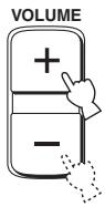
5 Press SURROUND repeatedly (or press SURROUND and then press ◀/▷) on the remote control to select a surround mode.
Signals input from 2-channel sources are played back on multiple channels.
For more information on surround modes, see page 46.
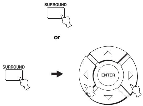
flowchart
graph TD
    A["SURROUND"] --> B["OR"]
    C["SURROUND"] --> D["OR"]
    D --> E["ENTER"]
    style E fill:#f9f,stroke:#333,stroke-width:2px
Adjusting surround mode parameters
You can configure the parameters for Dolby Pro Logic II Music and DTS Neo:6 Music to fine-tune the surround sound effect.
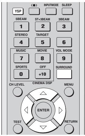
text_image
(●) INPUTMODE SLEEP YSP 5BEAM ST+3BEAM 3BEAM 1 2 3 STEREO TARGET 4 5 6 MUSIC MOVIE VOL MODE 7 8 9 SPORTS OFF SURROUND 0 +10 CH LEVEL CINEMA DSP MENU ENTER TEST RETURN1 Press YSP on the remote control to switch to the operation mode of this unit.

2 Press SURROUND on the remote control repeatedly (or press SURROUND and then press ◀/▷) to select PL II Music or Neo:6 Music.
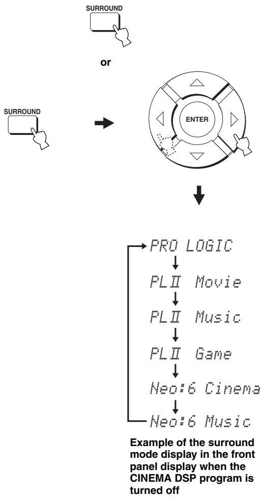
flowchart
graph TD
    A["Surround"] --> B["OR"]
    B --> C["ENTER"]
    C --> D["PRO LOGIC"]
    D --> E["PLII Movie"]
    E --> F["PLII Music"]
    F --> G["PLII Game"]
    G --> H["Neo:6 Cinema"]
    H --> I["Neo:6 Music"]
3 Press / to select the parameter.
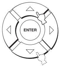
flowchart
graph TD
    A["ENTER"] --> B["Arrow"]
    B --> C["Arrow"]
    C --> D["Arrow"]
    D --> E["Arrow"]
    E --> F["Arrow"]
    F --> G["Arrow"]
    G --> H["Arrow"]
4 Press ◀ / ▷ to configure the parameter.

flowchart
graph TD
    A["ENTER"] --> B["Directional Arrow"]
    B --> C["Arrow pointing to the center"]
    C --> D["Arrow pointing right"]
    D --> E["Arrow pointing down"]
    E --> F["Arrow pointing up"]
    F --> G["Arrow pointing down"]
    G --> H["Arrow pointing up left"]
    H --> I["Arrow pointing down right"]
    I --> J["Arrow pointing up right"]
    J --> K["Arrow pointing down left"]
    K --> L["Arrow pointing up left"]
    L --> M["Arrow pointing down right"]
    M --> N["Arrow pointing up right"]
    N --> O["Arrow pointing down left"]
■ When Dolby Pro Logic II Music is selected
PANORAMA
Gives front left and right channel sound a wraparound effect, distributed throughout the entire surround sound field to give you an expansive feeling.
Choices: ON/OFF
Default setting: OFF
DIMENSION
Adjusts the difference in volume between front and surround channels to the volume balance you desire.
Control range: -3 (toward the surround direction) to +3 (toward the front direction)
Default setting: STD
CT WIDTH
Distributes the center channel sound to the left and right. If set to 0, center channel sounds output only from the center speaker.
Control range: 0 to 7
Default setting: 3
■ When DTS Neo:6 Music is selected
C. IMAGE
Adjusts the center image from three speakers (front and center) to varying degrees.
Control range: 0.0 (wider) to 1.0 (toward the center)
Default setting: 0.3
USING SOUND FIELD PROGRAMS
This unit is equipped with a variety of precise digital decoders that allow you to enjoy multi-channel playback from stereo or multi-channel sources. This unit is also equipped with a YAMAHA CINEMA DSP (digital sound field processing) chip containing several sound field programs which you can use to enhance your playback experience. Most of the sound field programs are precise digital recreations of actual acoustic environments found in famous concert halls, music venues and movie theaters.

The YAMAHA CINEMA DSP modes are compatible with all Dolby Digital, DTS and Dolby Surround sources.
Note
Choose a sound field program based on your listening preference and do not purely rely on the name of the sound field program itself.
What is a sound field?
A significant factor that creates the rich, full tones of a live instrument are the multiple reflections from the walls of the room. In addition to making the sound live, these reflections enable the listener to tell where the player is situated as well as the size and shape of the room in which the listening is sitting.
■ Elements of a sound field
In any environment, there are two distinct types of sound reflections that combine with the direct sound coming straight to our ears from the player's instrument to make up the sound field.
Early reflections
Reflected sounds reach our ears extremely rapidly (50 ms to 100 ms after the direct sound) after reflecting from one surface only (from the ceiling or a wall, for example). Early reflections help add clarity to the direct sound.
Reverberations
These are caused by reflections from more than one surface (i.e. wall, ceiling, the back of the room, etc.) so numerous that they merge together to form a continuous sonic afterglow. They are non-directional and lessen the clarity of the direct sound.
Direct sound, early reflections and subsequent reverberation taken together help us to determine the subjective size and shape of the room, and it is this information that the digital sound field processor reproduces in order to create sound fields.
If you could create the appropriate early reflections and subsequent reverberations in your listening room, you would be able to create your own listening environment. The acoustics in your room could be changed to those of a concert hall, a dance floor or a listening room of virtually any size at all. This ability to create sound fields at will is exactly what YAMAHA has done with the CINEMA DSP technology.
Sound field program descriptions
You can select from the following sound field programs based on your listening preference when you play music, movie or sports sources.
Notes
- There is only one sports sound field program available.
- For details on how to switch between the available sound field programs, see page 53.
| Sound field program | Source | Feature |
| Music Video | Music | This program produces a vibrant environment and lets you feel as if you are at an actual jazz or rock concert. |
| Concert Hall | This program creates a rich surround effect of a large round concert hall with a great deal of presence, emphasizing the extension of sounds, and lets you feel as if you are seated close to the center of the stage. | |
| Jazz Club | This program recreates the acoustic environment of “The Bottom Line”, a famous jazz club in New York and lets you feel as if you are seated right in front of the stage. | |
| Sci-Fi | Movie | This program clearly reproduces dialogs and special sound effects of the latest science fiction films and lets you feel a broad and expansive cinematic space amid silence. |
| Spectacle | This program reproduces the wide and grand environment and lets you have added impressions on spectacular scenes with strong visual impacts. | |
| Adventure | This program reproduces the thrilling environment of the latest action films and lets you feel the dynamic and excitement of fast-moving scenes. | |
| SPORTS | Sports | This program reproduces the energetic environment of live sports broadcasting, converging a commentator's voice on the center and broadening the overall atmosphere of the stadium, and lets you feel as if you are seated at an actual stadium or a ball park. |
Turning on CINEMA DSP programs
You can select from three different sound field programs (MUSIC, MOVIE and SPORTS) depending on the type of sources you want to enjoy.
Notes
- The CINEMA DSP programs are not available if the stereo mode (see page 44) or the target mode (see page 45) is selected as the beam mode.
- If the CINEMA DSP programs are not available, “Prohibit” appears in the front panel display when you press one of the sound field program buttons on the remote control.
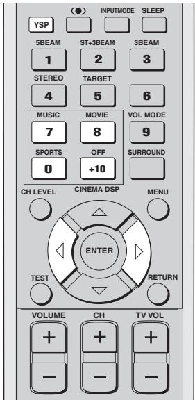
text_image
(●) INPUTMODE SLEEP YSP 5BEAM ST+3BEAM 3BEAM 1 2 3 STEREO TARGET 4 5 6 MUSIC MOVIE VOL MODE 7 8 9 SPORTS OFF SURROUND 0 +10 CH LEVEL CINEMA DSP MENU ENTER TEST RETURN VOLUME CH TV VOL - - -■ Music sound field programs
Select this sound field program when you play music sources. This program produces a vibrant atmosphere and lets you feel as if you are seated in an actual rock or jazz concert hall.
1 Press YSP on the remote control to switch to the operation mode of this unit.
2 Press MUSIC on the remote control to select the music sound field program.

3 Check that MUSIC is displayed in the front panel display and then press MUSIC on the remote control repeatedly (or press ◀/▷ on the remote control) to switch between the music sound field programs.
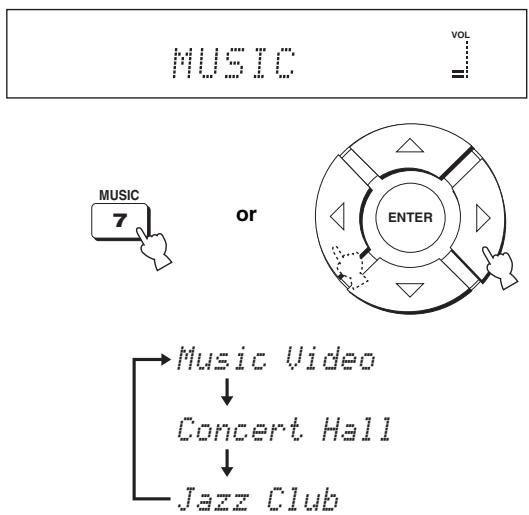
flowchart
graph TD
    A["MUSIC"] --> B["7"]
    C["OR"] --> D["ENTER"]
    E["Music Video"] --> F["Concert Hall"]
    G["Jazz Club"] --> H["End"]
For detailed descriptions of each sound field program, see “Sound field program descriptions” on page 52.
■ Movie sound field programs
Select this sound field program when you play movie sources, especially the ones encoded in Dolby Digital, DTS or Dolby Surround. This program clearly reproduces dialog and sound effects, thus creating a broad and expansive cinematic space amid silence.
1 Press YSP on the remote control to switch to the operation mode of this unit.
2 Press MOVIE on the remote control to select the movie sound field program.

3 Check that MOVIE is displayed in the front panel display and then press MOVIE on the remote control repeatedly (or press ◀ / ▶ on the remote control) to switch between the music sound field programs.
MOVIE


or
flowchart
graph TD
    A["Start"] --> B{Decision}
    B -->|Yes| C["Enter"]
    B -->|No| D["End"]
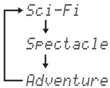
flowchart
graph TD
    A["Sci-Fi"] --> B["Spectacle"]
    B --> C["Adventure"]

For detailed descriptions of each sound field program, see “Sound field program descriptions” on page 52.
■ Sports sound field program
Select this sound field program when you play sports sources. This program densely concentrates the vocal sound of the commentator in the center while broadening the sound from the audience or the environment all around your listening room.
1 Press YSP on the remote control to switch to the operation mode of this unit.

2 Press SPORTS on the remote control to select the sports sound field program.
SPORTS is displayed in the front panel display.

SPORTS


- There is only one sports sound field program available.
- For detailed descriptions of each sound field program, see “Sound field program descriptions” on page 52.
Turning off CINEMA DSP programs
Turn off the CINEMA DSP programs if you want to enjoy the original sound without the sound field program effect.
1 Press YSP on the remote control to switch to the operation mode of this unit.

2 Press OFF on the remote control to turn off the sound field programs.

Adjusting CINEMA DSP levels
You can enjoy good quality sound with the factory preset parameters. However, you can also adjust the effect level of the CINEMA DSP programs relative to the level of the direct sound so that each sound field program can reflect your listening environment and your preference even more accurately.
1 Press YSP on the remote control to switch to the operation mode of this unit.

2 Press MUSIC, MOVIE or SPORTS on the remote control to select the desired sound field program.

or

or

3 Press / on the remote control. DSP LEVEL is shown in the front panel display.
DSP LEVEL: 0dB VOL
4 Press ◀/▷ on the remote control to adjust the effect level of the CINEMA DSP programs.
flowchart
graph TD
    A["Start"] --> B{Decision}
    B -->|Yes| C["Enter"]
    B -->|No| D["End"]
Control range: -6 dB to +3 dB
- A larger value increases the effect level.
- A smaller value decreases the effect level.
USING THE VOLUME MODE
The night listening modes are designed to improve listenability at lower volumes or at night. In addition, you can limit the volume level of the TV so that it will not vary suddenly to a great extent whenever the contents being broadcast change (i.e. due to commercials, etc.).
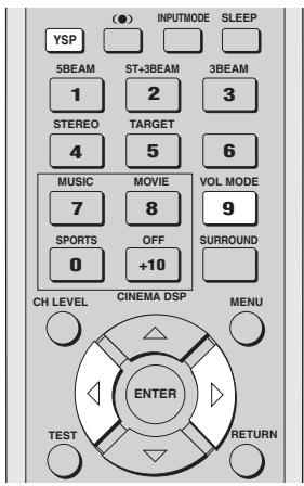
text_image
(●) INPUTMODE SLEEP YSP 5BEAM ST+3BEAM 3BEAM 1 2 3 STEREO TARGET 4 5 6 MUSIC MOVIE VOL MODE 7 8 9 SPORTS OFF SURROUND 0 +10 CH LEVEL CINEMA DSP MENU ENTER TEST RETURN1 Press YSP on the remote control to switch to the operation mode of this unit.

2 Press VOL MODE on the remote control to switch to the volume mode.
The NIGHT indicator lights up in the front panel display.
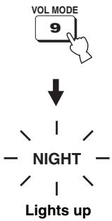
text_image
VOL MODE 9 ↓ NIGHT Lights up3 Press VOL MODE on the remote control repeatedly to select NIGHT:CINEMA, NIGHT:MUSIC, TV EQUAL VOL or NIGHT OFF.
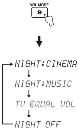
flowchart
graph TD
    A["VOL MODE 9"] --> B["NIGHT: CINEMA"]
    B --> C["NIGHT: MUSIC"]
    C --> D["TV EQUAL VOL"]
    D --> E["NIGHT OFF"]
- Select NIGHT:CINEMA when watching films to reduce the dynamic range of film soundtracks and make dialog easier to hear at lower volumes.
- Select NIGHT:MUSIC when listening to music sources to preserve ease-of-listening for all sounds.
- Select TV EQUAL VOL when watching TV programs.
- Select NIGHT OFF to turn off the night listening modes.
4 Press ◀ / ▷ on the remote control to adjust the effect level of compression while NIGHT:CINEMA, NIGHT:MUSIC or TV EQUAL VOL is displayed.
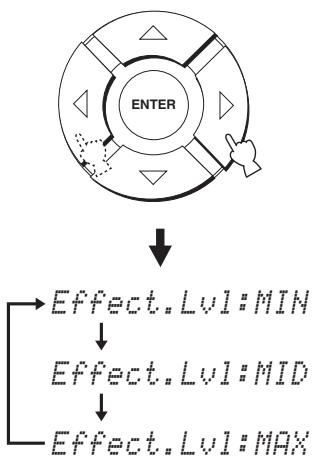
flowchart
graph TD
    A["ENTER"] --> B["Effect.Lvl:MIN"]
    A --> C["Effect.Lvl:MID"]
    A --> D["Effect.Lvl:MAX"]
- Select Effect.Lvl:MIN for minimum compression.
- Select Effect.Lvl:MID for standard compression.
- Select Effect.Lvl:MAX for maximum compression.
Note
The volume mode settings are canceled if you press STANDBY/ON on the front panel or on the remote control or if you disconnect the power supply cable from the AC wall outlet.
USING TruBass
This unit can produce the perception of an improved low frequency performance with the aid of the SRS TruBass technology, which improves bass even without a subwoofer and provides deeper, richer bass in the presence of a subwoofer.
Note
The TruBass is not available when the target mode is selected as the beam mode (see page 45).
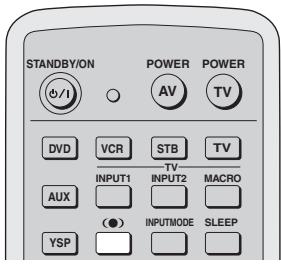
text_image
STANDBY/ON POWER POWER AV TV DVD VCR STB TV INPUT1 INPUT2 MACRO AUX (●) INPUTMODE SLEEP YSP1 Press (●) on the remote control.
The current setting (TruBass MID, TruBass DEEP, or TruBass OFF) is shown in the front panel display.


TruBass MID VOL

TruBass DEEP VOL

TruBass OFF VOL
2 Press (●) on the remote control repeatedly to turn on SRS TruBass.
TruBass MID or TruBass DEEP is shown in the front panel display.
You can select TruBass MID or TruBass DEEP depending on the type of material you are playing.


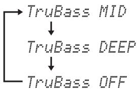
flowchart
graph TD
    A["TruBass MID"] --> B["TruBass DEEP"]
    B --> C["TruBass OFF"]

TruBass MID

TruBass DEEP
- Select TruBass MID for standard effects.
- Select TruBass DEEP for maximum effects.
3 Press (●) on the remote control repeatedly to turn off SRS TruBass.
TruBass OFF is shown in the front panel display.
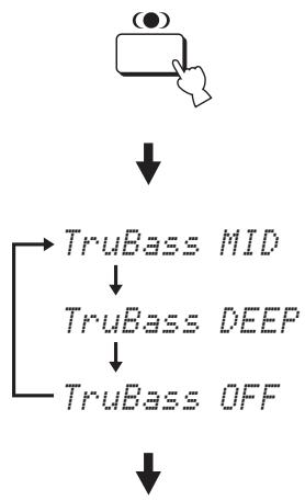
flowchart
graph TD
    A["●"] --> B["TruBass MID"]
    B --> C["TruBass DEEP"]
    C --> D["TruBass OFF"]
TruBasis OFF VOL
USING THE SLEEP TIMER
Use this feature to automatically set this unit to the standby mode after a specified time period. The sleep timer is useful if you are going to sleep after a certain amount of time while this unit is still playing back a source.
Setting the sleep timer
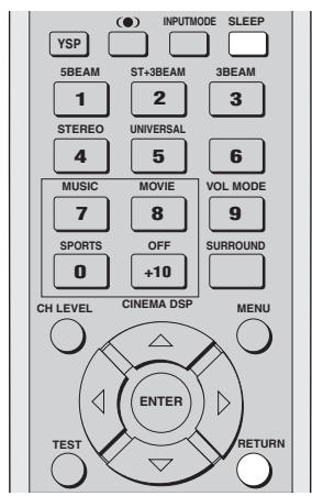
text_image
(●) INPUTMODE SLEEP YSP 5BEAM ST+3BEAM 3BEAM 1 2 3 STEREO UNIVERSAL 4 5 6 MUSIC MOVIE VOL MODE 7 8 9 SPORTS OFF SURROUND 0 +10 CH LEVEL CINEMA DSP MENU ENTER TEST RETURN1 Press SLEEP on the remote control repeatedly to set the amount of time for the sleep timer.
Choices: 120 min, 90 min, 60 min, 30 min, OFF The SLEEP indicator in the front panel display flashes while switching the amount of time for the sleep timer.

flowchart
graph LR
    A["SLEEP"] --> B["Star"]
    style A fill:#f9f,stroke:#333
    style B fill:#ccf,stroke:#333
Each time you press SLEEP on the remote control, the front panel display changes as shown below.
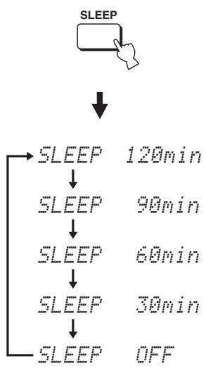
flowchart
graph TD
    A["SLEEP"] --> B["↓"]
    B --> C["SLEEP 120min"]
    C --> D["SLEEP 90min"]
    D --> E["SLEEP 60min"]
    E --> F["SLEEP 30min"]
    F --> G["SLEEP OFF"]
2 Wait for a few seconds without operating this unit to confirm the setting for the sleep timer.
The SLEEP indicator lights up in the front panel display, indicating that the sleep timer is activated.
Canceling the sleep timer
1 Press SLEEP on the remote control repeatedly so that SLEEP OFF appears in the front panel display.


LEEP
OFF

2 Wait for a few seconds without operating this unit to confirm the setting for the sleep timer.
The SLEEP indicator disappears from the front panel display, indicating that the sleep timer is deactivated.
SLEEP
Disappears
Note
The previous setting for the sleep timer before you deactivate it is stored in the system memory and automatically restored when you make a new setting next time.

The sleep timer setting can also be deactivated if you press STANDBY/ON on the front panel or on the remote control to set this unit to the standby mode or unplug the power supply cable from the AC outlet.
BASIC SETUP
If you cannot run AUTO SETUP successfully or if an error occurs during the AUTO SETUP procedure, you can use BASIC SETUP to individually set the parameters of this unit in the following order:
1) ROOM TYPE (Room type)
2) INSTALLED POSITION (Installed position of this unit)
3) ROOM SIZE (Room size)

- You can save the settings optimized by the AUTO SETUP procedure (see page 36). A set of settings optimized according to specific conditions of your listening environment can be recalled later depending on the varying conditions of your listening environment (see page 37).
- In order to fine-tune the listening environment parameters, as well as to make advanced settings for speaker positions, sound beams, digital input and the OSD, see MANUAL SETUP (see page 68).
- Items with an asterisk (*) appearing next to them may be displayed differently on your screen depending on your individual settings.
Note
Each listening environment parameter must be set before the next parameter in order is set.
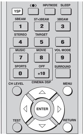
text_image
(●) INPUTMODE SLEEP YSP 5BEAM ST+3BEAM 3BEAM 1 2 3 STEREO TARGET 4 5 6 MUSIC MOVIE VOL MODE 7 8 9 SPORTS OFF SURROUND 0 +10 CH LEVEL CINEMA DSP MENU ENTER TEST RETURN■ Displaying the SET MENU screen
1 Press YSP on the remote control to switch to the operation mode of this unit.

2 Press MENU on the remote control. The SET MENU screen appears on your TV.
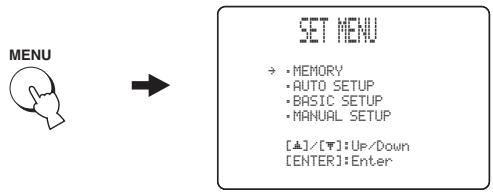
flowchart
graph LR
    A["MENU"] --> B["SET MENU"]
    B --> C["• MEMORY\n• AUTO SETUP\n• BASIC SETUP\n• MANUAL SETUP\n[▲"]/[▼]:Up/Down\n["ENTER"]:Enter]

- The control buttons used for SET MENU are displayed on the bottom of the screen.
- To return to the previous screen while using SET MENU, press RETURN on the remote control.
- To resume cursor button operations after changing the control area by pressing an input selector button, press TEST on the remote control.
- To cancel the SET MENU screen, press MENU once more.
- You can also perform the following operations in the front panel display.
- If you press an input selector button during the SET MENU operations, the cursor buttons become ineffective. In this case, press TEST once.
3 Press △ / ▽ to select BASIC SETUP and then press ENTER.
The following screen appears on your TV.
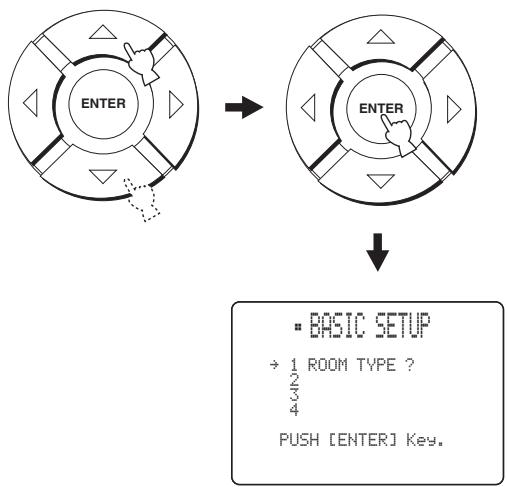
flowchart
graph TD
    A["ENTER"] --> B["ENTER"]
    B --> C["BASIC SETUP<br>→ 1 ROOM TYPE ?<br>2/3<br>4<br>PUSH [ENTER"] Key.]
■ ROOM TYPE (Room type)
4 Check that the following screen is displayed on your TV.
If this screen is not displayed, repeat steps 1 to 3.
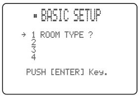
text_image
• BASIC SETUP → 1 ROOM TYPE ? 4 PUSH [ENTER] Key.5 Press ENTER.
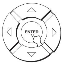
text_image
ENTER6 Press ◀ / ▷ to switch between the SQUARE and RECTANGLE selection screens and then press ENTER to select the desired setting.
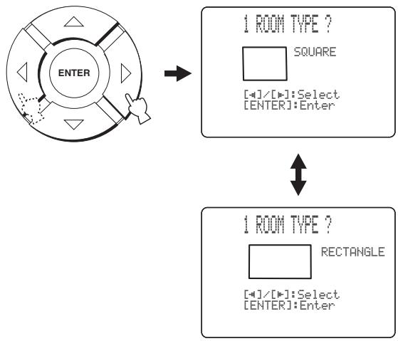
flowchart
graph TD
    A["ENTER"] --> B["1 ROOM TYPE ?"]
    B --> C["SQUARE"]
    B --> D["[-"]/[+]:Select]
    B --> E["[ENTER"]:Enter]
    C --> F["1 ROOM TYPE ?"]
    F --> G["RECTANGLE"]
    F --> H["[-"]/[+]:Select]
    F --> I["[ENTER"]:Enter]
- Select SQUARE if the shape of your listening room is nearest to a square.
- Select RECTANGLE if the shape of your listening room is nearest to a rectangle.

If the shape of your listening room is irregular, select the shape that most closely resembles your room.
In Example 1, the shape that best describes the listening room is RECTANGLE. In Example 2, it is SQUARE.
Example 1: Rectangular room
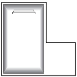
natural_image
Simple line drawing of a rectangular room corner with a horizontal shelf and a right-angle corner (no text or symbols)Example 2: Square room
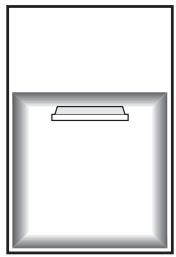
natural_image
Simple 3D rectangular frame with a small rectangular cutout on the bottom face (no text or symbols)7 Press ENTER to confirm the setting for the room type.
The following screen appears in the front panel display.
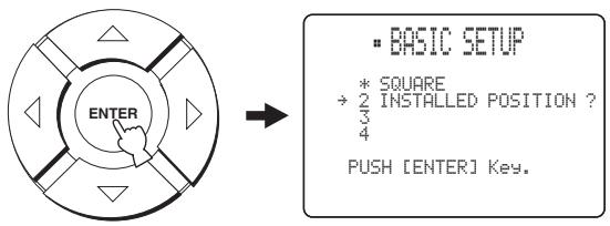
text_image
ENTER * SQUARE → 2 INSTALLED POSITION ? 4 PUSH [ENTER] Key.■ INSTALLED POSITION (Installed position of this unit)
8 Check that the following screen is displayed on your TV.
If this screen is not displayed, make settings for ROOM TYPE.
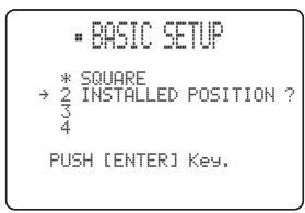
text_image
• BASIC SETUP * SQUARE → 2 INSTALLED POSITION ? 4 PUSH [ENTER] Key.9 Press ENTER.
If you selected SQUARE for ROOM TYPE (see page 63), four different installed position types in a square room are displayed.
If you selected RECTANGLE, eight different installed position types in a rectangular room are displayed.
If SQUARE is selected for ROOM TYPE
Select LEFT, CENTER, RIGHT or CORNER that best matches the installed position of this unit in your listening room.
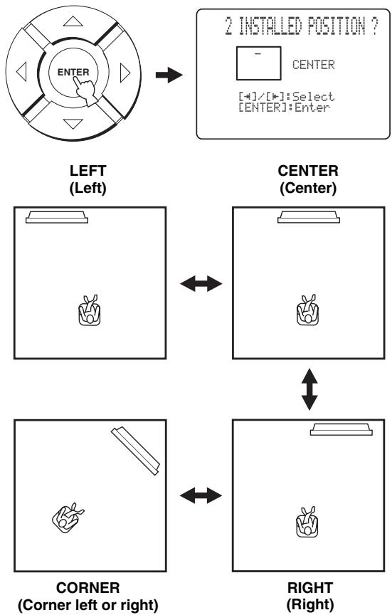
flowchart
graph TD
    A["LEFT (Left)"] --> B["2 INSTALLED POSITION ?"]
    B --> C["CENTER (Center)"]
    C --> D["CORNER (Corner left or right)"]
    D --> E["RIGHT (Right)"]
    style A fill:#f9f,stroke:#333
    style B fill:#ccf,stroke:#333
    style C fill:#cfc,stroke:#333
    style D fill:#fcc,stroke:#333
    style E fill:#cff,stroke:#333
If RECTANGLE is selected for ROOM TYPE
Select WIDE LEFT, WIDE CENTER, WIDE RIGHT, CORNER RIGHT, CORNER LEFT, NARROW LEFT, NARROW CENTER or NARROW RIGHT that best matches the installed position of this unit in your listening room.
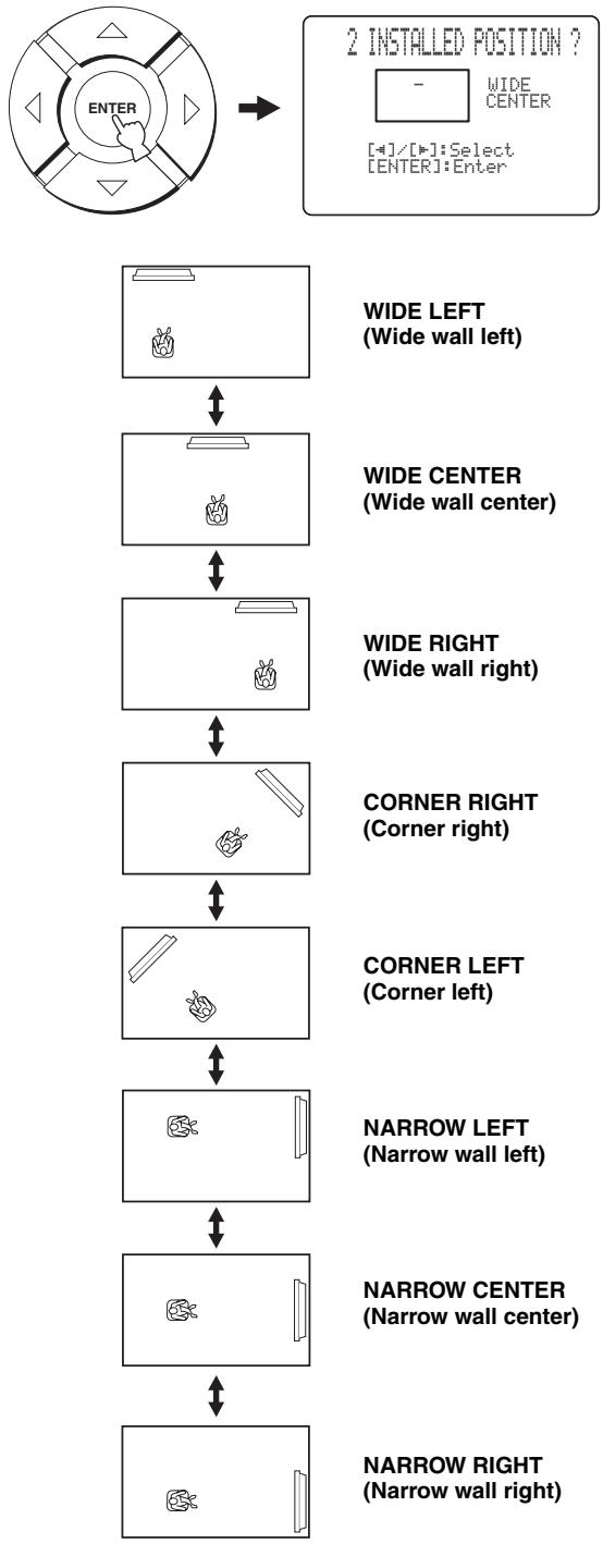
flowchart
graph TD
    A["ENTER"] --> B["2 INSTALLED POSITION ?"]
    B --> C1["WIDE CENTER (Wide wall left)"]
    C1 --> D1["WIDE CENTER (Wide wall center)"]
    D1 --> E1["WIDE RIGHT (Wide wall right)"]
    E1 --> F1["CORNER RIGHT (Corner right)"]
    F1 --> G1["CORNER LEFT (Corner left)"]
    G1 --> H1["NARROW LEFT (Narrow wall left)"]
    H1 --> I1["NARROW CENTER (Narrow wall center)"]
    I1 --> J1["NARROW RIGHT (Narrow wall right)"]
10 Press ◀ / ▷ to select the installed position type that best suits the installed position of this unit in your listening room and then press ENTER.
The following screen appears in the front panel display.
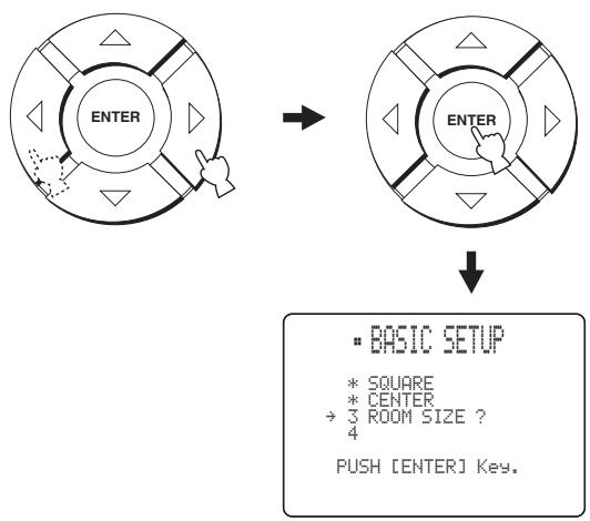
flowchart
graph TD
    A["ENTER"] --> B["ENTER"]
    B --> C["BASIC SETUP\n* SQUARE\n* CENTER\n→ 3 ROOM SIZE ?\n4\nPUSH [ENTER"] Key.]
■ ROOM SIZE (Room size)
11 Check that the following screen is displayed on your TV.
If this screen is not displayed, make settings for INSTALLED POSITION.
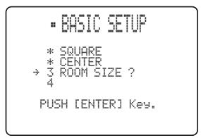
text_image
• BASIC SETUP * SQUARE * CENTER → 3 ROOM SIZE ? 4 PUSH [ENTER] Key.12 Press ENTER.
Three different room sizes (SMALL, MID or LARGE) are displayed for both SQUARE and RECTANGLE.
If SQUARE is selected for ROOM TYPE
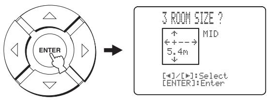
text_image
ENTER 3 ROOM SIZE ? ↑ ← + -- → 5.4m ↓ [+]/[●]:Select [ENTER]:Enter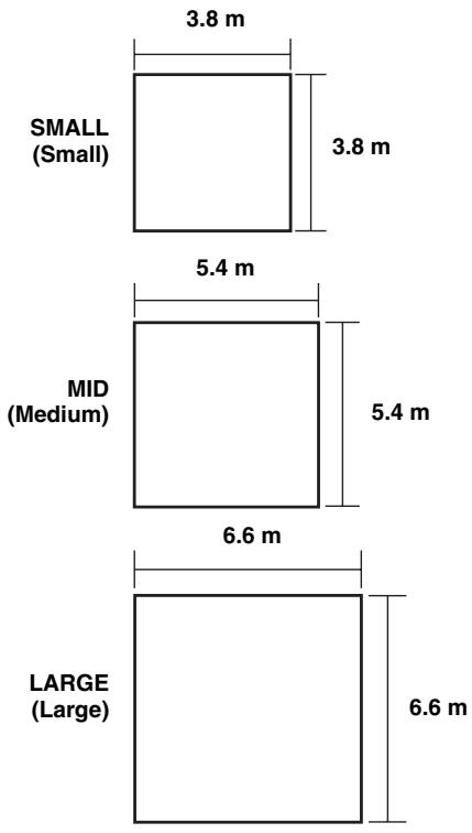
bar
| Category | Value | | -------------- | ------- | | SMALL (Small) | 3.8 m | | MID (Medium) | 5.4 m | | LARGE (Large) | 6.6 m |If RECTANGLE is selected for ROOM TYPE
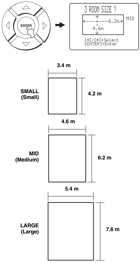
text_image
3 ROOM SIZE ? +----6.2m→ MID 4.6m [+]/[•]:Select [ENTER]:Enter 3.4 m SMALL (Small) 4.2 m 4.6 m MID (Medium) 6.2 m 5.4 m LARGE (Large) 7.6 m13 Press ◀ / ▷ to select the room size that best suits your listening room and then press ENTER.
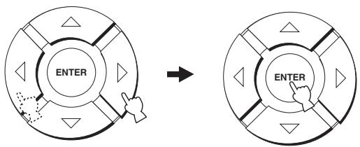
flowchart
graph TD
    A["ENTER"] --> B["Arrow"]
    B --> C["ENTER"]
■ SETUP OK (Confirming settings)
14 Check that the following screen is displayed on your TV.
If this screen is not displayed, make settings for ROOM SIZE.
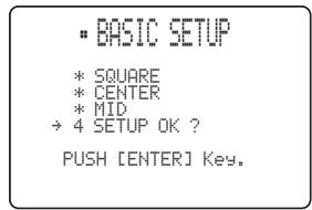
text_image
• BASIC SETUP * SQUARE * CENTER * MID → 4 SETUP OK ? PUSH [ENTER] Key.15 Press ENTER.
The following screen appears in the front panel display.
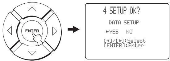
text_image
4 SETUP OK? DATA SETUP ▶YES NO [+]/[+] : Select [ENTER] : Enter16 Press ◀ / ▶ to select YES or NO and then press ENTER.
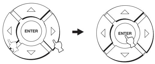
flowchart
graph TD
    A["ENTER"] --> B["Arrow"]
    B --> C["Control Panel"]
- Select YES to register the settings if they are satisfactory. The following screen appears, and your BASIC SETUP settings are registered.
4 SETUP OK?
Data Setting!
Please wait.
- Select NO to cancel the settings and return to the initial SET MENU screen.
SET MENU
- MEMORY
- AUTO SETUP
-BASIC SETUP
- MANUAL SETUP
[△]/[▽]:Up/Down
17 Press MENU to complete the BASIC SETUP procedure.
The SET MENU display disappears from your TV screen.
MENU

This completes the parameter settings for BASIC SETUP. To select a playback source and enjoy surround sound on this unit, see “PLAYBACK” on page 39.
MANUAL SETUP
To achieve the best quality surround sound, you can use MANUAL SETUP to fine-tune the listening environment parameters, as well as to make advanced settings for speaker positions, sound beams, digital input and the OSD. Change the initial settings (indicated in bold under each parameter) to reflect the needs of your own listening environment.

- You can save the settings optimized by the AUTO SETUP procedure (see page 36). A set of settings optimized according to specific conditions of your listening environment can be recalled later depending on the varying conditions of your listening environment (see page 37).
- Most of the parameters in SOUND MENU and BEAM MENU are automatically set when you run AUTO SETUP (see page 28). Use SOUND MENU and BEAM MENU to make additional adjustments.
- BEAM MENU allows you to make settings for the surround sound effects normally available in the speaker settings menu.
- Make settings for the parameters in BEAM MENU first before you make settings for the parameters in SOUND MENU, INPUT MENU and DISPLAY MENU.
SOUND MENU
Use to manually adjust various parameters related to the sound output.
| Item | Features | Page |
| TONE CONTROL | Adjusts the output level of high-frequency or low-frequency sound. | 74 |
| BEAM LEVEL | Adjusts the output level of each beam. | 75 |
| SUBWOOFER SET | Adjusts the various subwoofer settings. | 75 |
| MUTE LEVEL | Adjusts the muting level. | 76 |
| AUDIO DELAY | Adjusts audio delay. | 76 |
| ROOM EQ | Adjusts the tonal quality of the listening room. | 76 |
| DD/DTS Dynamic Range | Adjusts the dynamic range of Dolby Digital or DTS signals. | 76 |
BEAM MENU
Use to manually adjust various parameters related to the sound beam output.
| Item | Features | Page |
| SETTING PARAMETERS | Adjusts listening room and listening position settings. | 70 |
| BEAM ADJUSTMENT | Adjusts various beam settings. | 71 |
| IMAGE LOCATION | Adjusts the position of the front left and right speakers. | 74 |
INPUT MENU
Use to manually adjust various parameters related to the audio and video input.
| Item | Features | Page |
| INPUT ASSIGNMENT | Assigns jacks according to the component to be used. | 77 |
| INPUT MODE | Selects the initial input of the source. | 77 |
| INPUT TRIM | Adjusts the input level of the source. | 78 |
| INPUT RENAME | Renames the displayed input source. | 78 |
DISPLAY MENU
Use to manually adjust various parameters related to the display.
| Item | Features | Page |
| DIMMER SET | Adjusts the brightness of the display. | 79 |
| OSD SET | Adjusts the display position and the background color of the OSD. | 79 |
| UNIT SET | Changes the display unit of measurement. | 79 |
Using MANUAL SETUP
Use the remote control to access and adjust each parameter.
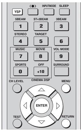
text_image
(●) INPUTMODE SLEEP YSP 5BEAM ST+3BEAM 3BEAM 1 2 3 STEREO TARGET 4 5 6 MUSIC MOVIE VOL MODE 7 8 9 SPORTS OFF SURROUND 0 +10 CH LEVEL CINEMA DSP MENU ENTER TEST RETURN
You can adjust the SET MENU parameters while the unit is reproducing sound.
1 Press YSP on the remote control to switch to the operation mode of this unit.

2 Press MENU on the remote control.
The SET MENU screen appears on your TV.
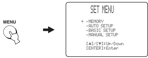
flowchart
graph LR
    A["MENU"] --> B["SET MENU"]
    B --> C["• MEMORY\n• AUTO SETUP\n• BASIC SETUP\n• MANUAL SETUP\n[▲"]/[▼]: Up/Down\n["ENTER"]: Enter]

- The control buttons used for SET MENU are displayed on the bottom of the screen.
- To return to the previous screen while using SET MENU, press RETURN on the remote control.
- To resume cursor button operations after changing the control area by pressing an input selector button, press TEST on the remote control.
- To cancel the SET MENU screen, press MENU once more.
- You can also perform the following operations in the front panel display.
- If you press an input selector button during the SET MENU operations, the cursor buttons become ineffective. In this case, press TEST once.
3 Press △ / ▽ to select MANUAL SETUP and then press ENTER.
The following screen appears on your TV.
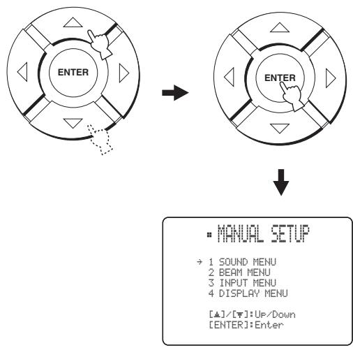
flowchart
graph TD
    A["ENTER"] --> B["ENTER"]
    B --> C["MANUAL SETUP"]
    C --> D["→ 1 SOUND MENU\n2 BEAM MENU\n3 INPUT MENU\n4 DISPLAY MENU\n[▲"]/[▼]:Up/Down\n["ENTER"]:Enter]
4 Press / to select a sub menu and then press ENTER.
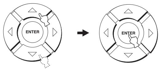
flowchart
graph TD
    A["ENTER"] --> B["Arrow"]
    B --> C["ENTER"]
5 Press / / / and ENTER to configure each parameter.
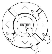
flowchart
graph TD
    A["ENTER"] --> B["Arrow 1"]
    A --> C["Arrow 2"]
    A --> D["Arrow 3"]
    A --> E["Arrow 4"]
    A --> F["Arrow 5"]
6 Press MENU to exit.
The OSD disappears from your TV screen.

BEAM MENU
Use to manually adjust various parameters related to the sound beam output.
SET MENU → MANUAL SETUP → BEAM MENU
2 BEAM MENU
→ A) SETTING PARAMETERS B) BEAM ADJUSTMENT C) IMAGE LOCATION
[△]/[▼]:Up/Down
■ SETTING PARAMETERS (Setting parameters)
Use to set the position of this unit in your listening room and the distance of this unit from the listening position.
When you make settings for each parameter, other related parameters are automatically adjusted to best match your listening environment.
Note
If you make adjustments in SETTING PARAMETERS, the beam optimization settings made in the AUTO SETUP procedure will be lost. If you want to keep the beam optimization settings made in the AUTO SETUP and make further adjustments, adjust settings in BEAM ADJUSTMENT first (see page 71).
A) SETTING PARAMETER 1/3
→ INSTALLED POSITION ……FLAT TO WALL INSTALLED HEIGHT ……1.0m
[▲]/[▼]:Up/Down[■]/[■]:Sel
INSTALLED POSITION (Installed position of this unit)
Use to adjust the installed position of this unit.
Choices: FLAT TO WALL (Parallel to wall installation), ANGLE TO WALL OR CORNER (Corner installation)
FLAT TO WALL
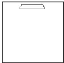
natural_image
Blank white image with a thin rectangular outline at the top (no text or symbols)ANGLE TO WALL
OR CORNER
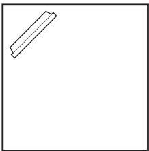
natural_image
Simple line drawing of a rectangular frame with a diagonal line on the left side (no text or symbols)- Select FLAT TO WALL if this unit is installed in parallel with the wall in your listening room. Adjust the width and length of your listening room as well as the distance of the listening position from this unit and the distance of the center of this unit from the left wall.
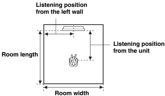
text_image
Listening position from the left wall Room length Room width Listening position from the unitChoices for the room width and length: 2.0 m to 12.0 m
Choices for the listening position from this unit: 2.0 m to 9.0 m
Choices for the listening position from the left wall: 0.6 m to 11.4 m
Room width and length
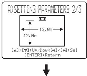
text_image
A)SETTING PARAMETERS 2/3 12.0m [▲]/[▼]:Up/Down[▲]/[▼]:Sel [ENTER]:ReturnListening position from the unit and the left wall
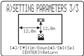
text_image
A)SETTING PARAMETERS 3/3 12.0m 12.0m [▲]/[▼]:Up/Down[▲]/[▼]:Sel [ENTER]:Return- Select ANGLE TO WALL OR CORNER if this unit is installed in the corner in your listening room. Adjust the width and length of your listening room as well as the distance of the listening position from this unit and the distance of the center of this unit from the left wall.
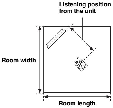
text_image
Listening position from the unit Room width Room lengthChoices for the room width and length:
2.0 m to 12.0 m
Choices for the listening position from this unit:
2.0 m to 9.0 m
Choices for the listening position from the left wall:
0.6 m to 11.4 m
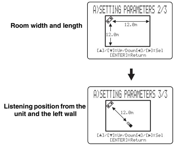
text_image
A)SETTING PARAMETERS 2/3 Room width and length 12.0m 12.0m [▲]/[▼]:Up/Down[▲]/[▼]:Sel [ENTER]:Return ↓ A)SETTING PARAMETERS 3/3 Listening position from the unit and the left wall 12.0m [▲]/[▼]:Up/Down[▲]/[▼]:Sel [ENTER]:ReturnNote
When you set the INSTALLED POSITION parameter in BASIC SETUP (see page 64) or MANUAL SETUP (see page 70), the parameters newly set for the width and length of your listening room are automatically set as the factory default value.
INSTALLED HEIGHT (Installed height of this unit)
Use to adjust the installed height of this unit.
Control range: 0.0 m to 3.0 m
Initial setting: 1.0 m
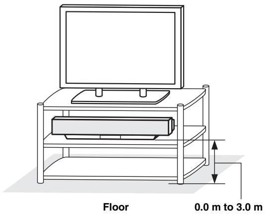
text_image
Floor 0.0 m to 3.0 m■ BEAM ADJUSTMENT (Beam adjustment)
Use to manually adjust the various speaker beam angles. We recommend that you select 5 beam mode before adjusting these parameters.
Notes
- When INSTALLED POSITION is adjusted in BASIC SETUP (see page 64) or MANUAL SETUP (see page 70), the factory default value is automatically set for this parameter except when FOCAL LENGTH is set to CENTER (see page 73).
- Depending on the beam mode settings (see page 42), some speaker positions may not be available for selection. In this case, “--” is displayed. When using the stereo plus 3 beam mode, set the surround left and right signals to be output from the front left and right speakers.
B) BEAM ADJUSTMENT
→ a) HORIZONTAL ANGLE
b)UVERTICAL ANGLE
c)BEAM TRAVEL LENGTH
d>FOCAL LENGTH
e) TREBLE GAIN
[血]/[下]:Up/Down
HORIZONTAL ANGLE (Horizontal angle)
Use to adjust the horizontal angle of beams for each speaker. By adjusting the horizontal angle of the beams, you can optimize the sound beam paths. A test tone is automatically output.
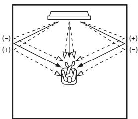
flowchart
graph TD
    A["Top Box"] --> B["Central Flower"]
    C["Left Side"] --> B
    D["Right Side"] --> B
    B --> E["Bottom Left"]
    B --> F["Bottom Right"]
    style B fill:#f9f,stroke:#333,stroke-width:2px
Choices: L90° to R90°
Adjust towards L (left) to move the direction of the output to the left and adjust towards R (right) to move it to the right.
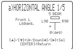
text_image
a)HORIZONTAL ANGLE 1/5 Front L L60deg. 5 BEAM L90 R90 * 0(deg) [▲]/[▼]:Up/Down[▲]/[▼]:Sel [ENTER]:ReturnVERTICAL ANGLE (Vertical angle)
Use to adjust the vertical angle of sound beams for each speaker. By altering the beam path, you can optimize sound beam angles.
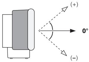
text_image
(+) 0° (-)Choices: -45^ to +45^
Initial setting: 0^
- Adjust towards – (minus) to move the angle downward.
- Adjust towards + (plus) to move the angle upward.
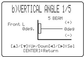
text_image
b)VERTICAL ANGLE 1/5 Front L 0deg. 5 BEAM (+) 0deg (-) [▲]/[▼]:Up/Down[▲]/[▼]:Sel [ENTER]:ReturnNote
A test tone is automatically output.
BEAM TRAVEL LENGTH (Beam travel length)
Use to set the distance that sound beams travel after being output and reflected off the wall until they arrive at the listening position for each speaker.
The lines in the illustration below indicate the distance.
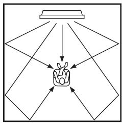
flowchart
graph TD
    A["Input 1"] --> C["Central Unit"]
    B["Input 2"] --> C
    D["Input 3"] --> C
    E["Input 4"] --> C
    F["Input 5"] --> C
    G["Input 6"] --> C
    H["Input 7"] --> C
    I["Input 8"] --> C
    J["Input 9"] --> C
    K["Input 10"] --> C
Choices: 0.3 m to 24.0 m
- Front L adjusts the distance the front left speaker sound beams travel.
- Front R adjusts the distance the front right speaker sound beams travel.
- Center adjusts the distance the center speaker sound beams travel.
- Surround L adjusts the distance the surround left speaker sound beams travel.
- Surround R adjusts the distance the surround right speaker sound beams travel.
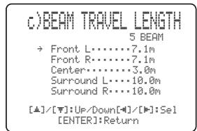
text_image
c)BEAM TRAVEL LENGTH 5 BEAM → Front L......7.1m Front R......7.1m Center......3.0m Surround L......10.0m Surround R......10.0m [▲]/[▼]:Up/Down[■]/[■]:Sel [ENTER]:ReturnFOCAL LENGTH (Focal length)
Use to set the distance from the front of this unit to the focal point of output for each speaker.
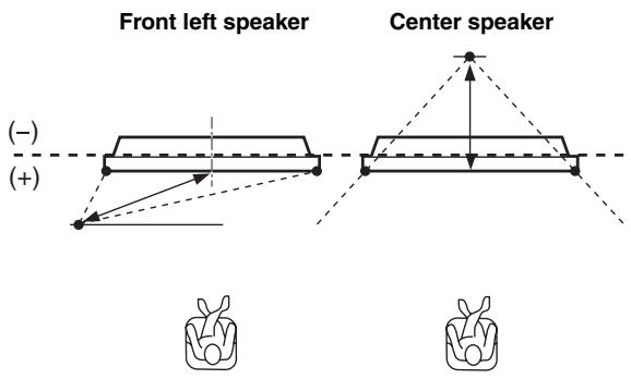
text_image
Front left speaker (-) (+) Center speakerChoices: -1.0 m to +13.0 m
Adjust towards - (minus) to move the focus outward and adjust towards + (plus) to move the focus towards the normal position.
- Front L adjusts the focal length for the front left sound beams.
- Front R adjusts the focal length for the front right sound beams.
- Center adjusts the focal length for the center sound beams. Initial setting: -0.5 m
- Surround L adjusts the focal length for the surround left sound beams.
- Surround R adjusts the focal length for the surround right sound beams.

We recommend that you use the initial setting ( -0.5 m ) for the center speaker.
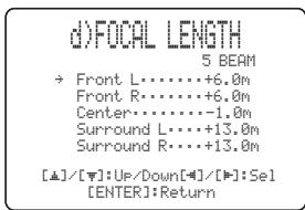
text_image
d)FOCAL LENGTH 5 BEAM → Front L......+6.0m Front R......+6.0m Center......-1.0m Surround L......+13.0m Surround R......+13.0m [▲]/[▼]:Up/Down[●]/[●]:Sel [ENTER]:ReturnTREBLE GAIN (Treble gain)
Use to adjust the high frequency output level of each speaker.

If the reflection point of the front left and right or surround left and right sound beams is a curtain or other acoustically absorbent surface, you can achieve more effective surround sound by increasing the treble level for those sound beams.
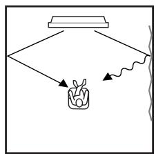
flowchart
graph TD
    A["Top Box"] --> B["Container"]
    B --> C["Arrow 1"]
    B --> D["Arrow 2"]
    B --> E["Arrow 3"]
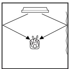
flowchart
graph TD
    A["Top Box"] --> B["Container"]
    B --> C["Output Line"]
Choices: -12.0 dB to +12.0 dB
Initial setting: 0 dB
- FL adjusts the high frequency output level of the front left speaker.
- FR adjusts the high frequency output level of the front right speaker.
- C adjusts the high frequency output level of the center speaker.
- SL adjusts the high frequency output level of the surround left speaker.
- SR adjusts the high frequency output level of the surround right speaker.
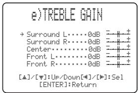
text_image
e)TREELE GAIN → Surround L·····0dB = -# + Surround R·····0dB = -# + Center·····0dB = -# + Front L·····0dB = -# + Front R·····0dB = -# + [▲]/[▼]:Up/Down[▼]/[▼]:Sel [ENTER]:Return■ IMAGE LOCATION (Image location)
Use to adjust the direction from which the front left and right speaker sound is heard by directing these audio signals so that they are also output from the center speaker.
Use this feature to redirect audio signals if the sound coming from the left and right speakers seems unnatural, such as when your listening position is not the center of your listening room.
You can only adjust this parameter when 3 beam mode or 5 beam mode is selected as the beam mode (see page 44).
Choices: ON, OFF
Setting range: 0% to 95%
Initial setting: 0%
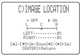
text_image
C) IMAGE LOCATION → OFF ▶ ON L C R LEFT……………0% RIGHT……………0% [▲]/[▼]:Up/Down[▲]/[▼]:Sel [ENTER]:ReturnLEFT (Left)
Adjusts audio signals towards the left.
The higher the percentage, the louder the output from the center.
Without adjustment
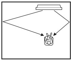
flowchart
graph TD
    A["Top Box"] --> B["Container"]
    B --> C["Bottom Box"]
With the front left speaker adjusted
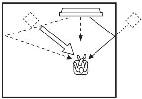
flowchart
graph TD
    A["Input"] --> B["Processing"]
    B --> C["Output"]
    style A fill:#f9f,stroke:#333
    style C fill:#bbf,stroke:#333
RIGHT (Right)
Adjusts audio signals towards the right.
The higher the percentage, the louder the output from the center.
Without adjustment
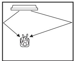
flowchart
graph TD
    A["Top Box"] --> B["Container"]
    B --> C["Bottom Box"]
With the front right speaker adjusted
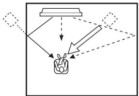
flowchart
graph TD
    A["Input"] --> B["Process"]
    B --> C["Output"]
    style A fill:#f9f,stroke:#333
    style C fill:#bbf,stroke:#333
SOUND MENU
Use to manually adjust various parameters related to the sound output.
SET MENU → MANUAL SETUP → SOUND MENU
1 SOUND MENU
→ A) TONE CONTROL
B)BEAM LEVEL
C) SUBWOOFER SET
D>MUTE LEVEL
E)AUDIO DELAY
F>ROOM EQ
G>DD/DTS Dynamic Range
[△]/[▽]:Up/Down
■ TONE CONTROL (Tone control)
You can adjust the tonal quality of your speakers.
A) TONE CONTROL

[▲]/[▼]:Up/Down[■]/[■]:Sel
TREBLE (Treble)
Use to adjust the high frequency response.
Choices: -12 dB to +12 dB
Initial setting: 0 dB
BASS (Bass)
Use to adjust the low frequency response.
Choices: -12 dB to +12 dB
Initial setting: 0 dB
BEAM LEVEL (Beam level)
Use to manually balance the speaker levels between the front left or surround left speakers and each speaker selected.
When setting the front right, center or surround left speakers or the subwoofer, the test tone is output from the front left speakers and the selected speaker position.
When setting the surround right speaker, the test tone is output alternately from the surround left and right speakers.
The factory default value is automatically set for this parameter depending on the parameters set in AUTO SETUP, BASIC SETUP or ROOM EQ in MANUAL SETUP.
Depending on the beam mode settings, some channels may not be available for selection. In this case, NONE is displayed.
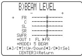
text_image
B)BEAM LEVEL → FR ————+ C ———— SL ———— SR ———— SWFR ———— *OUT : FL ▶FR *MODE: 5 BEAM [▲]/[▼]: Up/Down[▲]/[▶]: Sel [ENTER]: Return- FR adjusts the balance of the front left and front right speakers.
- C adjusts the balance of the front left and center speakers.
- SL adjusts the balance of the front left and surround left speakers.
- SR adjusts the balance of the surround left and surround right speakers.
- SWFR adjusts the balance of the front left speaker and subwoofer.
■ SUBWOOFER SET (Subwoofer set)
Use to manually adjust various subwoofer settings.
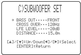
text_image
O)SUBWOOFER SET → BASS OUT···FRONT CROSS OVER···120Hz LFE LEVEL···-20dB DISTANCE···15.0m [▲]/[▼]:Up/Down[▲]/[▼]:Select [ENTER]:ReturnBASS OUT (Bass out)
Low-frequency (bass) signals can be directed to the subwoofer or the front left and right speaker positions. This setting also determines the routing of LFE (low-frequency effect) signals found in Dolby Digital or DTS sources.
- Select SWFR if you connect a subwoofer. LFE and low-frequency signals from other channels are directed to the subwoofer according to the speaker settings.
- Select FRONT if you do not use a subwoofer. LFE and low-frequency signals from other channels are directed to the front speakers according to the speaker settings (even if you have previously set the front speakers to SMALL).
CROSS OVER (Cross over)
When BASS OUT is set to SWFR, you can use this feature to select a cross-over (cut-off) frequency for all low-frequency signals. All frequencies below the selected frequency will be sent to the subwoofer speaker position. Choices: 80Hz, 100Hz, 120Hz
LFE LEVEL (Low-frequency effect level)
Select to adjust the output level of the LFE (low-frequency effect) channel according to the capacity of your subwoofer. The LFE channel carries low-frequency special effects which are only added to certain scenes. This setting is effective only when this unit decodes Dolby Digital or DTS signals.
Choices: -20 to 0 dB
DISTANCE (Distance)
Select to adjust the distance of the subwoofer from the listening position.
Choices: 0.3 to 15.0 m
Initial setting: 3.0 m
■ MUTE LEVEL (Muting level)
Use to adjust how much the mute function reduces the volume level.
Choices: MUTE, -20 dB
- Select MUTE to completely halt all sound output.
- Select -20 dB to reduce the current volume level by 20 dB.
D)MUTE LEVEL
▶MUTE -20dB
[4]/[1]:Select
■ AUDIO DELAY (Audio delay)
Use to delay the sound output and synchronize it with the video image. This may be necessary when using certain LCD monitors or projectors.
Choices: 0 to 160 msec
E) AUDIO DELAY
AUDIO DELAY...30msec
[4]/[5]:Select
■ ROOM EQ (Room equalizer)
Use to change the tonal qualities of your listening room when the unit is mounted on the wall.
Choices: MOUNT (Mount),
REFLECTING (Reflectivity type)
F)ROOM EQ
→ MOUNTING·····SHELF REFLECTING···NORMAL
[▲]/[▼]:Up/Down[■]/[■]:Sel
MOUNT (Mount)
Use to enhance medium to low range sounds.
Choices: WALL (Wall mount), SHELF (Shelf mount)
- Select WALL if this unit is mounted on the wall in your listening room.
- Select SHELF if this unit is mounted on the shelf in your listening room.
REFLECTING (Reflectivity type)
Use to select the reflectivity of your listening room.
Choices: NORMAL (Normal), HI ECHO (High echo)
- Select NORMAL if your listening room has a normal reflectivity.
- Select HI ECHO if your listening room has highly reflective surfaces such as concrete walls.
■ DD/DTS Dynamic Range (Dynamic range of Dolby Digital and DTS signals)
Use to select the amount of dynamic range compression to be applied to the speakers. This setting is effective only when the unit is decoding Dolby Digital and DTS signals. Dynamic range is the difference between the smallest sound that can be heard above the noise of the equipment and the biggest sound that can be heard without distortion. Choices: MIN (minimum), STD (standard),
MAX (maximum)
G)DD/0TS Dynamic Range
MIN STD ▶MAX
[4]/[5]:Select
Select to adjust the speaker compression.
- Select MIN for listening to sources at low volume levels.
- Select STD for general use.
- Select MAX for feature films.
INPUT MENU
Use to manually adjust various parameters related to the audio and video input.
SET MENU → MANUAL SETUP → INPUT MENU
3 INPUT MENU
→ A) INPUT ASSIGNMENT
B) INPUT MODE
C) INPUT TRIM
D) INPUT RENAME
[▲]/[▼]:Up/Down
[ENTER]:Enter
■ INPUT ASSIGNMENT (Input assignment)
Use to assign the optical and coaxial digital input jacks of this unit to other components if the initial settings of this unit do not correspond to your needs. By assigning other components to the input jacks on this unit, you can display the name of the connected component in the front panel display and OSD, and operate the component with the input selector button of the same name. If you connect a component to the input jacks of this unit and do not assign it, the default component name for that input jack is displayed in the front panel and OSD when selected.
- Select OPTICAL IN (1) to assign components to the TV/STB OPTICAL DIGITAL IN jack of this unit. Choices: TV, VCR
- Select OPTICAL IN (2) to assign components to the AUX OPTICAL DIGITAL IN jack of this unit. Choices: AUX, DVD
(4) INPUT ASSIGNMENT 1/4
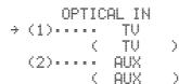
[▲]/[▼]:Up/Down[■]/[■]:Se
[ENTER]:Return
- Select COAX IN (3) to assign components to the DVD COAXIAL DIGITAL IN jack of this unit. Choices: DVD, AUX
A) INPUT ASSIGNMENT 2/4
COAX IN
→ (3)…… DVD
( DVD )
[▲]/[▼]:Up/Down[-4]/[■]:Se
[ENTER]:Return
- Select COMPONENT (1) to assign components to the STB COMPONENT VIDEO IN jacks of this unit.
Choices: TV, VCR
- Select COMPONENT (2) to assign components to the DVD/AUX COMPONENT VIDEO IN jacks of this unit.
Choices: DVD, AUX
A) INPUT ASSIGNMENT 3/4
COMPONENT
→ (1)…… TU
( TU )
(2)…… DVD
( DVD )
[▲]/[▼]:Up/Down[■]/[■]:Sel
[ENTER]:Return
- Select COMPOSITE (3) to assign components to the DVD/AUX VIDEO IN jack of this unit. Choices: AUX, DVD
A) INPUT ASSIGNMENT 4/4
COMPOSITE
→ (3)…… AUX
( AUX )
[▲]/[▼]:Up/Down[-#/][#]:Sel
[ENTER]:Return
■ INPUT MODE (Input mode)
Use to designate the input mode for the input sources connected to the DIGITAL INPUT jacks when you turn on the power of this unit. For information on the types of audio signals that can be output by this unit, see “Surround modes and recommended sources” on page 46.
Choices: AUTO, LAST
B) INPUT MODE
▶ AUTO LAST
[≠]/[≠]:Select
[ENTER]:Return
- Select AUTO to allow this unit to automatically detect the type of input signal and select the appropriate input mode.
- Select LAST to set this unit to automatically select the last input mode used for that input source. If the type of input signal is different from the setting, no sounds will be produced.
■ INPUT TRIM (Input trim)
Use to adjust the input level of the input source.
C) INPUT TRIM
→ TV ANALOG……-3.0dB
OPTICAL……-3.0dB
VCR ANALOG……-3.0dB
AUX OPTICAL……-3.0dB
DVD COAXIAL……-3.0dB
[▲]/[▼]:Up/Down[■]/[■]:Sel
[ENTER]:Return
- Select TV ANALOG to adjust the level of audio and video signals input at the TV/STB analog audio input jacks of this unit.
Control range: -6.0 dB to 0.0 dB Initial setting: -3.0 dB
- Select TV OPTICAL to adjust the level of audio and video signals input at the TV OPTICAL IN jack of this unit.
Control range: -6.0 dB to 0.0 dB Initial setting: -3.0 dB
- Select VCR ANALOG to adjust the level of audio and video signals input at the VCR analog audio input jacks of this unit.
Control range: -6.0 dB to 0.0 dB Initial setting: -3.0 dB
- Select AUX OPTICAL to adjust the level of audio and video signals input at the AUX OPTICAL IN jack of this unit.
Control range: -6.0 dB to 0.0 dB Initial setting: -3.0 dB
- Select DVD COAXIAL to adjust the level of audio and video signals input at the COAXIAL IN jack of this unit.
Control range: -6.0 dB to 0.0 dB Initial setting: -3.0 dB
■ INPUT RENAME (Input rename)
Use to change the name of the input source in the OSD and the front panel display. Press an input selector button (TV, STB, DVD, VCR, or AUX) to select the component you want to change the name for and then perform the following procedure.
D) INPUT RENAME
AUX -> AUX
[=]/[#:Position
[=]/[":Character
[ENTER]:Return
1 Press TEST on the remote control.

2 Press ◀ / ▷ to place the _ (underbar) under the space or the character you want to edit. The _ (underbar) flashes.
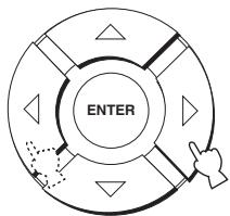
flowchart
graph TD
    A["ENTER"] --> B["Arrow to Right"]
    B --> C["Arrow to Left"]
    C --> D["Arrow to Down"]
    D --> E["Arrow to Up"]
    E --> F["Arrow to Down"]
    F --> G["Arrow to Left"]
    G --> H["Arrow to Right"]
3 Press / to select the desired character.
- You can use up to 8 characters for each input. - Press to change the character in the following order or press to go in the reverse order: A to Z, a space, 0 to 9, a space, a to z, a space, #, *, +, etc.

flowchart
graph TD
    A["ENTER"] --> B["Arrow"]
    B --> C["Arrow"]
    C --> D["Arrow"]
    D --> E["Arrow"]
    E --> F["Arrow"]
    F --> G["Arrow"]
    G --> H["Arrow"]
    H --> I["Arrow"]
    I --> J["Arrow"]
4 Repeat steps 1 to 3 to rename each input.
5 Press ENTER to exit.
The new names are registered, and the display returns to the previous screen.
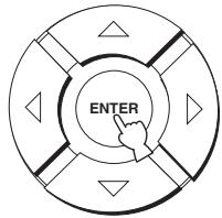
text_image
ENTERDISPLAY MENU
Use to manually adjust various parameters related to the display.
SET MENU → MANUAL SETUP → OPTION MENU
4 DISPLAY MENU
→ A) DIMMER SET
B)OSD SET
C>UNIT SET
[△]/[▽]:Up/Down
■ DIMMER SET (Dimmer settings)
Use to adjust the brightness of the front panel display.
A) DIMMER SET
→ STANDARD DIMMER...OFF
Use to adjust the brightness of the front panel display when you operate this unit by using the control buttons on the front panel or on the remote control.
Choices: -2, -1, OFF
AUTO DIMMER (Auto dimmer)
If no operation is performed for a specified period, the front panel display dims. Use to adjust the brightness of the front panel display in this case.
Choices: DISPLAY OFF, -3 to -1 (based on the
STANDARD DIMMER setting), OFF
■ OSD SET (OSD settings)
Use to adjust the display position and the background color of the OSD.
B)05D SET
→ OSD SHIFT......0
OSD SHIFT (OSD shift)
Use to adjust the vertical position of the OSD. Adjust towards the - (minus) direction to raise the position of the OSD, and adjust towards the + (plus) direction to lower it.
Choices: -5 to +5
Initial setting: 0
OSD BACK COLOR (OSD background color)
Use to select the background color of the OSD.
Choices: BLUE, GRAY
■ UNIT SET (Unit settings)
(U.S.A. and Canada models only)
Use this to change the display unit of measurement.
Choices: METERS, FEET
COUNIT SET
▶ METERS FEET
[4]/[1]:Select
- Select METERS to input speaker distances in meters.
- Select FEET to input speaker distances in feet.
ADJUSTING SYSTEM PARAMETERS
Setting the maximum volume level
You can set the maximum volume level so that this unit will not output sound beyond the limited volume level.
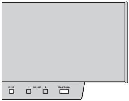
text_image
INPUT VOLUME STAND/BAYON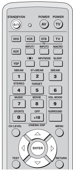
text_image
STANDBY/ON POWER POWER AV TV DVD VCR STB TV INPUT1 INPUT2 MACRO AUX ● INPUTMODE SLEEP YSP 5BEAM ST+3BEAM 3BEAM 1 2 3 STEREO TARGET 4 5 6 MUSIC MOVIE VOL MODE 7 8 9 SPORTS OFF SURROUND 0 +10 CH LEVEL CINEMA DSP MENU TEST RETURN ENTER1 Press STANDBY/ON on the front panel or on the remote control to turn off the power of this unit.
Front panel
or

Remote control
2 Press and hold INPUT on the front panel and then press STANDBY/ON on the front panel to turn on the power of this unit.
MAX VOLUME SET is shown in the front panel display.

STANDBY/ON


MAX VOLUME SET =
3 Release INPUT on the front panel.
4 Press ENTER on the remote control.
text_image
ENTER5 Press ◀ / ▷ to adjust the maximum volume level.
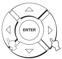
flowchart
graph TD
    A["ENTER"] --> B["Arrow Left"]
    B --> C["Arrow Right"]
    C --> D["Arrow Down"]
    D --> E["Arrow Up"]
    E --> F["Arrow Left"]
    style A fill:#f9f,stroke:#333
    style F fill:#f9f,stroke:#333
Control range: 0 dB to -99.0 dB
Control step: 1 dB
6 Press STANDBY/ON on the front panel or on the remote control to set this unit to the standby mode.
STANDBY/ON

Front panel
or

Remote control
The new setting for the maximum volume level will be activated when you turn on the power of this unit next time.
Protecting the current settings
You can protect the settings currently saved in the system memory from being accidentally erased or unwantedly changed.
1 Repeat steps 1 to 3 in “Setting the maximum volume level” on page 80.
2 Press △ / ▽ on the remote control so that MEMORY PROTECT is shown in the front panel display.

flowchart
graph TD
    A["ENTER"] --> B["Arrow"]
    B --> C["Arrow"]
    C --> D["Arrow"]
    D --> E["Arrow"]
    E --> F["Arrow"]
    F --> G["Arrow"]
    G --> H["Arrow"]
↓
MEMORY PROTECT VOL
3 Press ENTER.
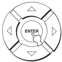
text_image
ENTER4 Press ◀ / ▷ to switch between PROTECT: ON and PROTECT: OFF.
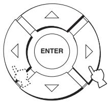
flowchart
graph TD
    A["ENTER"] --> B["Process Step 1"]
    B --> C["Process Step 2"]
    C --> D["Process Step 3"]
    D --> E["Process Step 4"]
    E --> F["Process Step 5"]
    F --> G["Process Step 6"]
    G --> H["Process Step 7"]
    H --> I["Process Step 8"]
    I --> J["Process Step 9"]
    J --> K["Process Step 10"]
↓
PROTECT: ON
↑↓
PROTECT: OFF =
- Select PROTECT: ON to activate the protection feature.
- Select PROTECT: OFF to deactivate the protection feature.
5 Press STANDBY/ON on the front panel or on the remote control to set this unit to the standby mode.

Front panel
or

Remote control
The new setting will be activated when you turn on the power of this unit next time.
Initializing the current settings
You can reset all of the parameters of this unit to the factory presets. This procedure completely resets ALL the parameters in SET MENU.
Note
After performing the following procedure you must reset the ROOM TYPE, SP POSITION and ROOM SIZE parameters to match your surround sound environment.
1 Repeat steps 1 to 3 in "Setting the maximum volume level" on page 80.
2 Press / on the remote control so that FACTORY PRESET is shown in the front panel display.
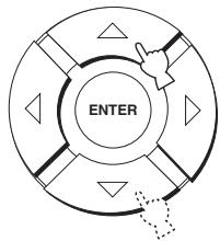
flowchart
graph TD
    A["Start"] --> B{Decision}
    B -->|Yes| C["Enter"]
    B -->|No| D["End"]
↓
FACTORY PRESET VOL
3 Press ENTER.

text_image
ENTER4 Press ◀ / ▷ to switch between PRESET: RESET and PRESET: CANCEL.

flowchart
graph TD
    A["ENTER"] --> B["Process Step 1"]
    B --> C["Process Step 2"]
    C --> D["Process Step 3"]
    D --> E["Process Step 4"]
    E --> F["Process Step 5"]
    F --> G["Process Step 6"]
    G --> H["Process Step 7"]
    H --> I["Process Step 8"]
    I --> J["Process Step 9"]
    J --> K["Process Step 10"]
↓
PRESET: RESET

PRESET: CANCEL =
- Select PRESET: RESET to reset all of the current settings.
- Select PRESET: CANCEL to cancel the resetting procedure.
5 Press STANDBY/ON on the front panel or on the remote control to set this unit to the standby mode.
Front panel
or

Remote control
The new setting will be activated when you turn on the power of this unit next time.
Adjusting the audio balance
You can adjust the sound beam output level of each speaker by using the test tone or the audio output being played back in each beam mode to achieve a more true-to-life surround sound experience.

If the level of a particular speaker cannot be adjusted, “-dB” appears in the front panel display.
■ Using the test tone
You can use the test tone feature to output a test tone from each speaker to manually balance the speaker levels. Use the test tone to set speaker levels so that the volume level of each speaker is identical when heard from your listening position.
Notes
- All the speaker levels cannot be adjusted when the stereo mode or the target mode is selected as the beam mode (see page 44).
- FRONT L/R cannot be adjusted when the stereo plus 3 mode is selected as the beam mode (see page 43).
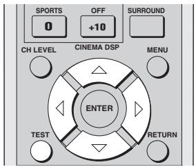
text_image
SPORTS 0 OFF +10 SURROUND CH LEVEL CINEMA DSP MENU ENTER TEST RETURN1 Press TEST on the remote control.
TEST LEFT appears in the front panel display and a test tone is output from the front left speaker.


TEST LEFT =
2 Press △ / ▽ to select the speaker you want to adjust.
The front panel display changes as follows.
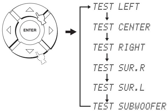
flowchart
graph TD
    A["ENTER"] --> B["TEST LEFT"]
    A --> C["TEST CENTER"]
    A --> D["TEST RIGHT"]
    A --> E["TEST SUR.R"]
    A --> F["TEST SUR.L"]
    A --> G["TEST SUBWOOFER"]
Note
TEST SUBWOOFER is only available when a subwoofer is connected to this unit and SWFR is selected for BASS OUT in SOUND MENU (see page 75).
3 Press ◀ / ▷ to adjust speaker volumes.
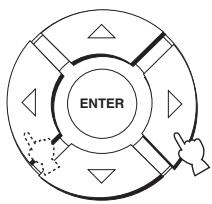
flowchart
graph TD
    A["ENTER"] --> B["Process Step 1"]
    B --> C["Process Step 2"]
    C --> D["Process Step 3"]
    D --> E["Process Step 4"]
    E --> F["Process Step 5"]
    F --> G["Process Step 6"]
    G --> H["Process Step 7"]
    H --> I["Process Step 8"]
    I --> J["Process Step 9"]
    J --> K["Process Step 10"]
Control range: -10 dB to +10 dB
4 Press VOLUME +/- on the remote control to adjust the volume level of this unit.
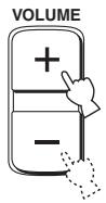
5 Press TEST when you have completed all your adjustments.


To adjust the output level of your subwoofer, set BASS OUT to BOTH or SWFR (page 75).
■ Using the audio output being played back
You can also manually adjust the speaker levels while playing back an input source such as a DVD.
Notes
- All the speaker levels cannot be adjusted when the stereo mode is selected as the beam mode (see page 44).
- FRONT L/R cannot be adjusted when the stereo plus 3 mode is selected as the beam mode (see page 43).
- Only CENTER can be adjusted when the target mode is selected as the beam mode (see page 45).
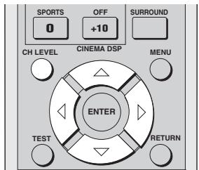
text_image
SPORTS 0 OFF +10 SURROUND CH LEVEL CINEMA DSP MENU ENTER TEST RETURN1 Press CH LEVEL repeatedly (or press CH LEVEL and then / ) to select the speaker you want to adjust.
The front panel display changes as follows.
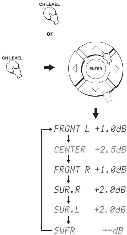
flowchart
graph TD
    A["CH LEVEL"] --> B["OR"]
    B --> C["ENTER"]
    C --> D["FRONT L +1.0dB"]
    D --> E["CENTER -2.5dB"]
    E --> F["FRONT R +1.0dB"]
    F --> G["SUR.R +2.0dB"]
    G --> H["SUR.L +2.0dB"]
    H --> I["SWFR --dB"]
2 Press ◀ / ▷ to adjust speaker volumes.
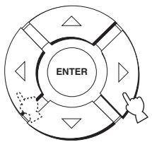
flowchart
graph TD
    A["ENTER"] --> B["Arrow Left"]
    A --> C["Arrow Right"]
    A --> D["Arrow Down"]
    A --> E["Arrow Up"]
    A --> F["Arrow Left"]
    style A fill:#f9f,stroke:#333
    style B fill:#ccf,stroke:#333
    style C fill:#cfc,stroke:#333
    style D fill:#fcc,stroke:#333
    style E fill:#cff,stroke:#333
    style F fill:#ffc,stroke:#333
Control range: -10 dB to +10 dB
3 Press CH LEVEL (or wait for a few seconds without operating this unit) when you have completed your adjustment.

SELECTING THE INPUT MODE
You can select the type of audio input signals of the selected input source according to your preference or the conditions of the input source.

We recommend setting the input mode to AUTO in most cases.
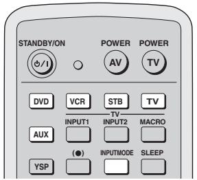
text_image
STANDBY/ON POWER POWER AV TV DVD VCR STB TV INPUT1 INPUT2 MACRO AUX (●) INPUTMODE SLEEP YSP1 Press one of the input selector buttons on the remote control to select the desired input source.
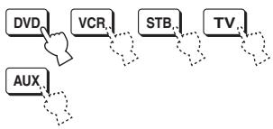
flowchart
graph TD
    A["DVD"] --> B["VCR"]
    B --> C["STB"]
    C --> D["TV"]
    E["AUX"] --> F["..."]
2 Press INPUTMODE on the remote control repeatedly to toggle between input modes.
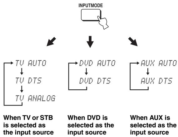
flowchart
graph TD
    A["INPUTMODE"] --> B["TV AUTO"]
    B --> C["TV DTS"]
    C --> D["TV ANALOG"]
    E["When TV or STB is selected as the input source"] --> F["TV AUTO"]
    F --> G["TV DTS"]
    G --> H["TV ANALOG"]
    I["When DVD is selected as the input source"] --> J["DVD AUTO"]
    J --> K["DVD DTS"]
    L["When AUX is selected as the input source"] --> M["AUX AUTO"]
    M --> N["AUX DTS"]
Notes
- The input mode of VCR is fixed to ANALOG. However, if the TV OPTICAL IN jack of this unit is assigned to VCR, AUTO, DTS and ANALOG become available as the input mode of VCR (see page 77).
- ANALOG is not available as the input mode of DVD and AUX.
- AUTO
Automatically selects audio input signals in the following priority order:
Use this input mode in most cases.
• DTS
Selects only digital signals encoded in DTS.
Compared to AUTO, this input mode provides greater stability while playing back CDs or LDs encoded in DTS.
• ANALOG
Selects only analog signals.
Even when both digital and analog signals are input simultaneously, only analog signals are selected.
Notes
- When the input mode is set to AUTO, this unit automatically plays back multi-channel sources in the selected input mode.
- ANALOG cannot be selected as an input mode if analog signals are not being input from the selected input source.

You can adjust the default input mode to be selected when the power of this unit is turned on (see page 77).
REMOTE CONTROL FEATURES
In addition to controlling this unit, the remote control can also operate other A/V components made by YAMAHA and other manufacturers. To control other components, you must set up the remote control with the appropriate remote control codes.
Note
Depending on the external A/V component you are using, you may not be able to operate the component with the remote control, even if a remote control code is set. In this case, operate the component using the supplied remote control.
Setting remote control codes
You can control other components by setting the appropriate remote control codes. Codes can be set up for each input area (TV, STB, DVD, VCR and AUX).
For a complete list of available remote control codes, refer to “LIST OF REMOTE CONTROL CODES” at the end of this manual.
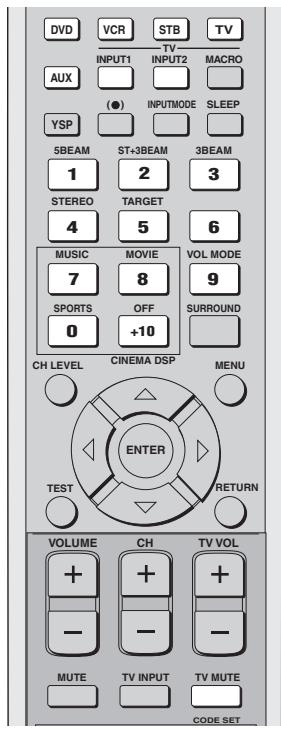
text_image
DVD VCR STB TV INPUT1 INPUT2 MACRO AUX (●) INPUTMODE SLEEP YSP 5BEAM ST+3BEAM 3BEAM 1 2 3 STEREO TARGET 4 5 6 MUSIC MOVIE VOL MODE 7 8 9 SPORTS OFF SURROUND 0 +10 CH LEVEL CINEMA DSP MENU ENTER TEST RETURN VOLUME CH TV VOL + - - - - - MUTE TV INPUT TV MUTE CODE SET1 While holding down CODE SET, press the input selector button for the component you want to set up and then without releasing CODE SET, enter the remote control code using the numeric buttons.
The following illustrations show an example of setting the remote control code for a DVD player made by YAMAHA.
Setting example: YAMAHA DVD input area
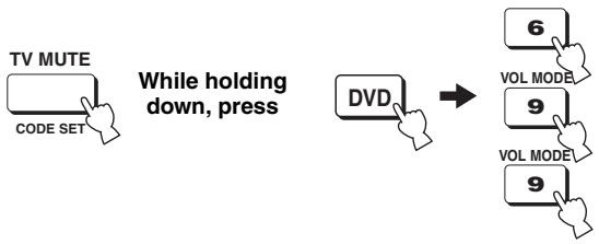
flowchart
graph LR
    A["TV MUTE\nCODE SET"] --> B["While holding down, press"]
    C["DVD"] --> D["→"]
    E["6\nVOL MODE"] --> F["9\nVOL MODE"]
    G["9"] --> H["9"]
2 Refer to "Controlling other components" on page 88 to operate the external component using the remote control.
If the external component functions correctly, the remote control code setup was successful.
If the external component does not function correctly, the remote control code may be incorrect. Confirm that the remote control code is correct (see “LIST OF REMOTE CONTROL CODES” at the end of this manual) and start over from step 1.
Note
If the manufacturer of your component has more than one code, try each of them until you find the correct one.
If the remote control is without batteries for more than 2 minutes, or if exhausted batteries remain in the remote control, the contents of the memory may be cleared. When the memory is cleared, insert new batteries and reset the remote control codes.
When changing the batteries, be careful not to press any of the buttons on the remote control. Doing so will clear the contents of the memory.
Controlling other components
■ Operating your TV
Press TV to select TV as the input source.
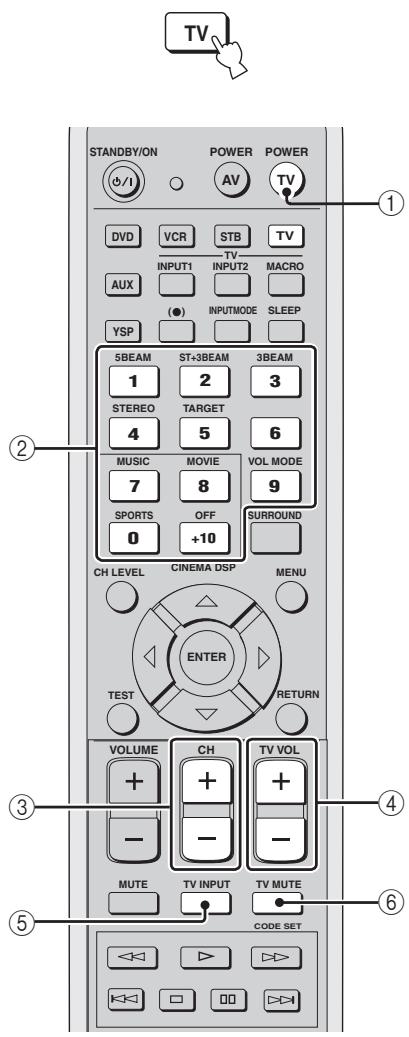
text_image
TV STANDBY/ON POWER POWER #(/) DVD VCR STB TV INPUT1 TV-TV MACRO AUX ●)(●) INPUTMODE SLEEP YSP 5BEAM ST+3BEAM 3BEAM 1 2 3 STEREO TARGET 4 5 6 MUSIC MOVIE VOL MODE 7 8 9 SPORTS OFF SURROUND 0 +10 CH LEVEL CINEMA DSP MENU ENTER TEST RETURN VOLUME CH TV VOL + + + - - - MUTE TV INPUT TV MUTE CODE SET① TV POWER
Turns on or off the power of your TV.
② Numeric buttons
Selects a TV channel for playback.
③ CH +/-
Switches between the available TV channels.
④ TV VOL +/-
Adjusts the audio output level of the TV.
⑤ TV MUTE
Temporarily mutes audio output from the TV.
⑥ TV INPUT
Switches the input source for the TV.
■ Operating your DVD player
Press DVD to select DVD as the input source.
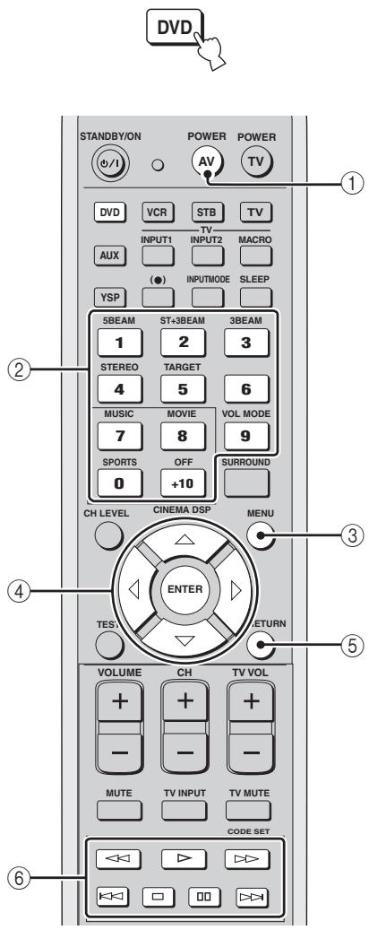
text_image
DVD STANDBY/ON POWER POWER AV TV ① DVD VCR STB TV INPUT1 INPUT2 MACRO AUX (●) INPUTMODE SLEEP YSP 5BEAM ST+3BEAM 3BEAM 1 2 3 STEREO TARGET 4 5 6 MUSIC MOVIE VOL MODE 7 8 9 SPORTS OFF SURROUND 0 +10 CH LEVEL CINEMA DSP MENU ENTER TESV RETURN VOLUME CH TV VOL + + + - - - - - MUTE TV INPUT TV MUTE CODE SET① AV POWER
Turns on or off the power of your DVD player.
② Numeric buttons
Use to enter numeric digits.
③ Operation buttons for DVD and VCR players
Use to perform DVD player operations, such as play and stop.
④ MENU
Displays the DVD menu.
⑤ Cursor buttons
Use to select DVD menu items.
⑥ RETURN
Use to return to the previous DVD menu screen or exit the DVD menu.
■ Operating your VCR player
Press VCR to select VCR as the input source.
#
Press YSP on the remote control to return to the operation mode of this unit.


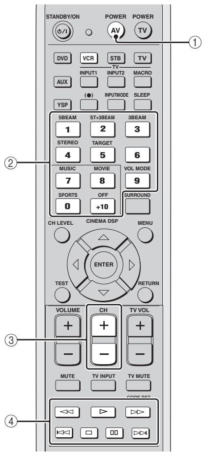
text_image
STANDBY/ON POWER POWER AV TV DVD VCR STB TV INPUT1 INPUT2 MACRO AUX (●) INPUTMODE SLEEP YSP 5BEAM ST+3BEAM 3BEAM 1 2 3 STEREO TARGET 4 5 6 MUSIC MOVIE VOL MODE 7 8 9 SPORTS OFF +10 SURROUND 0 CH LEVEL CINEMA DSP MENU TEST ENTER RETURN VOLUME CH TV VOL + + + - - - - MUTE TV INPUT TV MUTE CODE SET <>① AV POWER
Turns on or off the power of your VCR.
② Numeric buttons
Use to enter numeric digits.
③ CH +/-
Switches between the available VCR channels.
④ Operation buttons for DVD and VCR players
Use to perform VCR player operations, such as play and stop.
Using the TV macro
The TV macro feature makes it possible to perform a series of operations with the press of a single button. For example, when you want to play a DVD, you would normally turn on the component, select DVD as the input source and press the play button to start playback. The TV macro feature lets you perform all of these operations simply by pressing the DVD macro button.
Notes
- The ways to set macros differ if your TV does not have the tuning capability.
- If you press any control buttons on the remote control other than the ones used to set macros while setting macros, the setting procedure is automatically canceled.
- If it takes more than 10 seconds in steps 2 and 3, the setting procedure is automatically canceled. In this case, repeat from step 1.
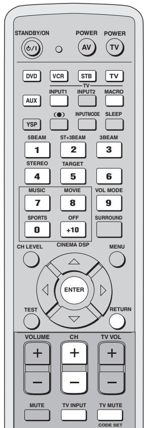
text_image
STANDBY/ON POWER POWER AV TV DVD VCR STB TV INPUT1 INPUT2 MACRO AUX (●) INPUTMODE SLEEP YSP 5BEAM ST+3BEAM 3BEAM 1 2 3 STEREO TARGET 4 5 6 MUSIC MOVIE VOL MODE 7 8 9 SPORTS OFF SURROUND 0 +10 CH LEVEL CINEMA DSP MENU TEST RETURN VOLUME CH TV VOL + + - - - MUTE TV INPUT TV MUTE CODE SET■ Setting macros for the TV with the tuning capability
1 Press and hold CODE SET on the remote control and then press one of the input selector buttons to select the input source you want to set macros for.
Proceed to step 2 while holding down CODE SET.
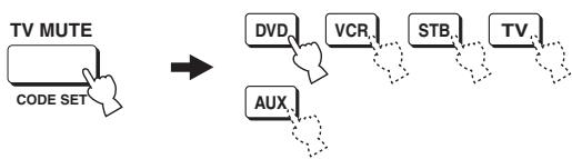
flowchart
graph TD
    A["TV MUTE\nCODE SET"] --> B["DVD"]
    A --> C["VCR"]
    A --> D["STB"]
    A --> E["TV..."]
    A --> F["AUX"]
2 Press MACRO on the remote control while holding down CODE SET.
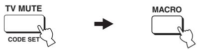
flowchart
graph LR
    A["TV MUTE\nCODE SET"] --> B["→"]
    B --> C["MACRO"]
3 Press CH +/- or the numeric buttons to select the TV channel.
Check that the TV screen changes to the tuner screen.
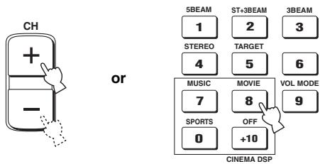
text_image
CH + - or 5BEAM ST+3BEAM 3BEAM 1 2 3 STEREO TARGET 4 5 6 MUSIC MOVIE VOL MODE 7 8 9 SPORTS OFF 0 +10 CINEMA DSP4 Press TV INPUT on the remote control repeatedly so that the screen changes to the display of the input source selected in step 1.

5 Press ENTER on the remote control to confirm the macro setting.
text_image
ENTER■ Setting macros for the TV without the tuning capability
1 Press and hold CODE SET on the remote control and then press one of the input selector buttons to select the input source you want to set macros for.
Proceed to step 2 while holding down CODE SET.
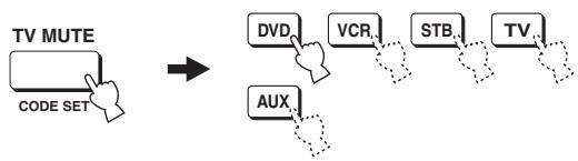
flowchart
graph LR
    A["TV MUTE\nCODE SET"] --> B["DVD"]
    A --> C["VCR"]
    A --> D["STB"]
    A --> E["TV"]
    A --> F["AUX"]
2 Press MACRO on the remote control while holding down CODE SET.

flowchart
graph LR
    A["TV MUTE\nCODE SET"] --> B["→"]
    B --> C["MACRO"]
3 Press INPUT1 on the remote control.

4 Press CH +/- or TV INPUT on the remote control repeatedly so that the screen changes to the display of the input source selected in step 1.
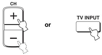
text_image
CH + - or TV INPUT5 Press ENTER on the remote control to confirm the setting.
text_image
ENTER■ Operating macros
1 Press and hold one of the input selector buttons for approximately 2 seconds to select the input source you want to operate macros for.
The TV input changes at the same time the input mode changes.
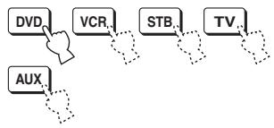
flowchart
graph TD
    A["DVD"] --> B["VCR"]
    B --> C["STB"]
    C --> D["TV"]
    D --> E["AUX"]
■ Canceling the macros
1 Press and hold CODE SET on the remote control and then press one of the input selector buttons to select the input source you want to cancel the macros for.
Proceed to step 2 while holding down CODE SET.
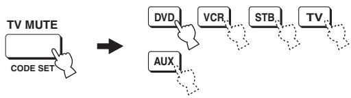
flowchart
graph LR
    A["TV MUTE\nCODE SET"] --> B["DVD"]
    B --> C["VCR"]
    C --> D["STB"]
    D --> E["TV"]
    E --> F["AUX"]
2 Press MACRO on the remote control while holding down CODE SET.
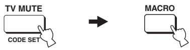
flowchart
graph LR
    A["TV MUTE\nCODE SET"] --> B["→"]
    B --> C["MACRO"]
3 Press ENTER on the remote control to cancel the macros.

text_image
ENTERTROUBLESHOOTING
Refer to the chart below when this unit does not function properly. If the problem you are experiencing is not listed below or if the instruction below does not help, set this unit to the standby mode, disconnect the power cord and contact the nearest authorized YAMAHA dealer or service center.
General
| Problem | Cause | Remedy | See page |
| This unit fails to turn on when STANDBY/ON is pressed, or enters the standby mode soon after the power has been turned on. | The power supply cable is not firmly connected to the AC wall outlet or to the AC inlet on the rear panel of this unit. | Connect the power supply cable firmly to the AC wall outlet or to the AC inlet on the rear panel of this unit. | 23 |
| This unit has been exposed to a strong external electric shock (such as lightning and strong static electricity). | Set this unit to the standby mode, disconnect the power supply cable, plug it back in after 30 seconds, then use it normally. | — | |
| This unit suddenly enters the standby mode. | The internal temperature becomes too high and the overheat protection circuitry has been activated. | Wait about 1 hour for this unit to cool down and then turn it back on. | — |
| The sleep timer has turned the unit off. | Turn on the power, and play the source again. | — | |
| No sound. | Incorrect input or output cable connections. | Connect the cables properly. If the problem persists, the cables may be defective. | 15 |
| No appropriate input source has been selected. | Select an appropriate input source with INPUT or the input selector buttons. | 39 | |
| The volume is turned down. | Turn up the volume. | 40 | |
| The sound is muted. | Press MUTE or VOLUME +/- on the remote control to resume audio output and then adjust the volume level. | 41 | |
| Signals this unit cannot reproduce (such as PCM signals with more than 96 kHz of sampling frequency) are being received from source component. | Play a source whose signals can be reproduced by this unit. | — | |
| Change the system settings of the source component. | — | ||
| The sound suddenly goes off. | The sleep timer has turned the unit off. | Turn on the power, and play the source again. | — |
| The sound is muted. | Press MUTE or VOLUME +/- on the remote control to resume audio output and then adjust the volume level. | 41 | |
| No sound from the effect speakers. | You are playing back the source or program in the stereo mode. | Press one of the beam mode buttons on the remote control to select a multi-channel playback mode and then try to play back the source or program once more. | 42 |
| No sound from the center speaker. | The output level of the center speaker is set to minimum. | Raise the level of the center speaker. | 83 |
| No sound from the surround speakers. | The output level of the surround speakers is set to minimum. | Raise the output level of the surround speakers. | 83 |
| No sound from the subwoofer. | BASS OUT in SUBWOOFER SET is set to FRONT. | Select SWFR or BOTH. | 75 |
| The source does not contain low bass signals. | |||
| Distorted or too little bass sound | CROSS OVER in SUBWOOFER SET is set incorrectly. | Set CROSS OVER correctly. | 75 |
| One of the night listening modes is currently selected. | Turn off the night listening modes. | 56 | |
| Too much bass sound | TruBass is currently turned on. | Turn off TruBass. | 58 |
| The volume level of the subwoofer is too high. | Turn down the volume level of the subwoofer. | — | |
| Surround sound effects are insubstantial. | The listening room is not a regular shape. | Install this unit in a square or rectangular shaped room. | — |
| There is no wall in the path of the sound beam. | Try placing a flat object, such as a board, in the path of the sound beam. | — | |
| Dolby Digital or DTS sources cannot be played. (Dolby Digital or DTS indicator does not light up in the front panel display.) | The connected component is not set to output Dolby Digital or DTS digital signals. | Make an appropriate setting following the operating instructions for your component. | — |
| The input mode is set to ANALOG. | Set the input mode to AUTO. | 86 | |
| There is noise interference when a subwoofer is not connected to this unit. | The protection circuitry was in operation because a source with strong bass elements was played back. | Turn down the volume level. | 40 |
| Select SWFR for BASS OUT. | 75 | ||
| Connect a subwoofer and adjust settings for SUBWOOFER SET. | 75 | ||
| On-screen display does not appear. | The VIDEO OUT (composite) jack of this unit is not connected to the video input jacks of your TV. | Connect the VIDEO OUT (composite) jack of this unit to the video input jacks of your TV. The OSD is not output at the COMPONENT VIDEO OUT jacks. | 16 |
| The video pin cable is not connected properly. | Connect the cable properly. | 16 | |
| TV is not selected as the input source. | Select TV as the input source. | 39 | |
| No picture is displayed for external components, such as a DVD player. | The video cable is not connected properly. | Connect the cable properly. | 16 |
| TV is not selected as the input source. | Select TV as the input source. | 39 | |
| This unit does not operate properly. | The internal microcomputer has been frozen by an external electric shock (such as lightning or excessive static electricity) or by a power supply with low voltage. | Disconnect the AC power supply cable from the outlet and then plug it in again after about 30 seconds. | — |
| There is noise interference from digital or high-frequency equipment. | This unit is too close to the digital or high-frequency equipment. | Move this unit further away from such equipment. | — |
| This unit does not output effect sounds properly. | The original source includes surround effects. | Disable surround effect settings on this unit. | — |
■ Remote control
| Problem | Cause | Remedy | See page |
| The remote control does not work and/or function properly. | Wrong distance or angle. | The remote control will function within a maximum range of 6 m and no more than 30 degrees off-axis from the front panel. | 24 |
| Direct sunlight or lighting (from an inverter type of fluorescent lamp, etc.) is striking the remote control sensor of this unit. | Reposition this unit. | — | |
| The batteries are weak. | Replace all batteries. | 24 | |
| You cannot operate external components with this unit's remote control. | The external component you want to operate is not selected as the input source. | Press INPUT on the front panel or the input selector buttons on the remote control to select the external component you want to operate. | 39 |
| The remote control code was not correctly set. | Set the remote control code correctly or try another code for the same manufacturer using the “LIST OF REMOTE CONTROL CODES” at the end of this manual. | 87 | |
| Even if the remote control code is correctly set, there are some models that do not respond to the remote control. | Use the remote control supplied with the external component. | — | |
| The cursor buttons do not work during SET MENU operation. | You pressed an input selector button. | Press TEST once. | — |
GLOSSARY
Audio formats
■ Dolby Digital
Dolby Digital is a digital surround sound system that gives you completely independent multi-channel audio. With 3 front channels (left, center, and right), and 2 surround stereo channels, Dolby Digital provides 5 full-range audio channels. With an additional channel especially for bass effects, called LFE (low frequency effect), the system has a total of 5.1-channels (LFE is counted as 0.1 channel). By using 2-channel stereo for the surround speakers, more accurate moving sound effects and surround sound environment are possible than with Dolby Surround. The wide dynamic range (from maximum to minimum volume) reproduced by the 5 full-range channels and the precise sound orientation generated using digital sound processing provide listeners with previously unheard of excitement and realism.
With this unit, any sound environment from monaural up to a 5.1-channel configuration can be freely selected for your enjoyment.
■ Dolby Pro Logic II
Dolby Pro Logic II is an improved technique used to decode vast numbers of existing Dolby Surround software. This new technology enables a discrete 5-channel playback with 2 front left and right channels, 1 center channel, and 2 surround left and right channels (instead of only 1 surround channel for conventional Pro Logic technology). Music and Game modes are also available for 2-channel sources in addition to the Movie mode.
■ Dolby Surround
Dolby Surround uses a 4 channel analog recording system to reproduce realistic and dynamic sound effects: 2 front left and right channels (stereo), a center channel for dialog (monaural), and a surround channel for special sound effects (monaural). The surround channel reproduces sound within a narrow frequency range. Dolby Surround is widely used with nearly all video tapes and laser discs, and in many TV and cable broadcasts as well. The Dolby Pro Logic decoder built into this unit employs a digital signal processing system that automatically stabilizes the volume on each channel to enhance moving sound effects and directionality.
■ DTS (Digital Theater Systems) Digital Surround
DTS digital surround was developed to replace the analog soundtracks of movies with a 6-channel digital sound track, and is now rapidly gaining popularity in movie theaters around the world. Digital Theater Systems Inc. has developed a home theater system so that you can enjoy the depth of sound and natural spatial representation of DTS digital surround in your home. This system produces practically distortion-free 6-channel sound (technically, a left, right and center channels, 2 surround channels, plus an LFE 0.1 channel as a subwoofer, for a total of 5.1-channels). The unit incorporates a DTS-ES decoder that enables 6.1-channel reproduction by adding the surround back channel to existing 5.1-channel format.
Neo:6
Neo:6 decodes the conventional 2-channel sources for 6 channel playback by the specific decoder. It enables playback with the full-range channels with higher separation just like digital discrete signal playback. Two modes are available; Music mode for playing music sources and Cinema mode for movies.
■ PCM (Linear PCM)
Linear PCM is a signal format under which an analog audio signal is digitized, recorded and transmitted without using any compression. This is used as a method of recording CDs and DVD audio. The PCM system uses a technique for sampling the size of the analog signal per very small unit of time. Standing for pulse code modulation, the analog signal is encoded as pulses and then modulated for recording.
Audio information
■ LFE 0.1 channel
This channel is for the reproduction of low bass signals. The frequency range for this channel is 20 Hz to 120 Hz. This channel is counted as 0.1 because it only enforces a low frequency range compared to the full-range reproduced by the other 5/6 channels in Dolby Digital or DTS 5.1/6.1-channel systems.
INDEX
A
Audio pin cable.... 16 to 19
AUTO SETUP 28
B
BASIC SETUP 62
Beam modes 42
C
Cable clamp....23
Cardboard microphone stand.... 30
Coaxial digital output jack 8
Coaxial digital input jack 8
D
Digital audio pin cable.... 17
Display....7,26
Dolby Digital 46
Dolby Pro Logic 46
Dolby Pro Logic II.... 46
DTS 46
DTS Neo:6....46
Dynamic range....76
F
Fastener....14
Front panel display 7
L
LFE 0.1 channel....75,95
M
MANUAL SETUP 68
MEMORY 36, 37
N
Night listening modes....56
0
On-screen display (OSD)....26
Optical cable 16, 19, 21
Optimizer microphone 29
P
PCM....86
Power supply cable 23
R
Remote control....9,24
Remote control code 87
s
Surround mode....46
Sleep timer 60
SET MENU 26
Sound field program 51
T
Test tone....83
TruBass 58
TV macro....90
V
Video pin cable 16
Volume mode....56
SPECIFICATIONS
AMP SECTION
• Maximum Output Power (EIAJ) 2 W (1 kHz, 10% THD, 4 Ω) × 40 20 W (100 Hz, 10% THD, 3 Ω) × 2
SPEAKER SECTION
Small dia. speakers .....4 cm cone magnetic shielding type × 40 Woofers .....10 cm cone magnetic shielding type × 2
- Input Jacks AUDIO VCR, TV/STB (Analog) (1 V, 32 kΩ) ... 2 pairs (Analog) AUDIO AUX, TV/STB (Optical) .... 2 (Digital) AUDIO DVD (Coaxial) .... 1 (Digital) COMPOSITE VIDEO, VCR, DVD/AUX, STB .... 3 COMPONENT VIDEO, DVD/AUX, STB .... 2 pairs
- Output Jacks SUBWOOFER (1.5 V, less than 120 Hz) ....1 (Subwoofer) VIDEO (1 Vp-p, 75 Ω) ....1 (Composite) COMPONENT VIDEO (Y: 1 Vp-p, 75 Ω P_B/P_R : 0.5 Vp-p, 75 Ω) ....1
- System Connector Jacks OPTIMIZER MIC ....1 (Microphone input) RS-232C ....1 (System control) REMOTE IN ....1 (System control) IR-OUT ....1 (System control)
GENERAL
- Power supply
[U.S.A. and Canada models] ...... AC 120 V, 60 Hz
[Australia model] AC 240 V, 50 Hz
[U.K. and Europe models] ...... AC 230 V, 50 Hz
[China model] ...... AC 220 V, 50 Hz
[Korea model] AC 220 V, 60 Hz
[General model] ...... AC 110–120 V, 50/60 Hz
[Asia model] ...... AC 220–240 V, 50/60 Hz
- Power Consumption 50 W
- Standby Power Consumption 0.1 W or less
- Dimensions (W x H x D) 1030 × 194 × 118 mm
- Weight 13.0 kg
* Specifications are subject to change without notice.
LIST OF REMOTE CONTROL CODES
LISTE DES CODES DE COMMANDE
LISTE DER FERNBEDIENUNGSCODES
LISTA ÖVER FJÄRRSTYRNINGSKODER
LISTA DEI CODICI DI TELECOMANDO
LISTA DE CÓDIGOS DE MANDO A DISTANCIA
LIJST MET AFSTANDSBEDIENINGSCODES
TV
| ADMIRAL | 292, 293, 216 |
| AIWA | 294, 276, 283, 284 |
| AKAI | 295, 296 |
| ALBA | 296 |
| AOC | 297 |
| BELL &HOWELL | 292 |
| BESTAR | 298 |
| BLAUPUNKT | 229, 222 |
| BLUE SKY | 298 |
| BRANDT | 223 |
| BROC SONIC | 297 |
| BUSH | 296 |
| BYD:SIGN | 201, 202 |
| CLATRONIC | 298 |
| CRAIG | 224 |
| CROSLEX | 225 |
CURTIS MATHIS
| 297, 226 | |
| DAEWOO | 297, 298, 224, 227, 228 |
| DAYTRON | 239 |
| DUAL | 298 |
| DWIN | 293, 281 |
| EMERSON | 297, 224, 239, 232 |
| FURGUSON | 223, 265, 266 |
| FIRST LINE | 298 |
| FISHER | 295, 233 |
| FRABA | 298 |
| FUJITSU | 289 |
| FUNAI | 277, 278 |
| GE | 293, 297, 234, 235, 236 |
GOODMANS 296, 298, 223
| GRUNDIG | 229, 238, 249 |
| HITACHI | 297, 239, 242, 243, 285 |
ICE 296
| IRRADIO | 296 |
| ITT/NOKIA | 244, 245 |
| JC PENNY | 293, 297, 234, 237 |
| JVC | 296, 246, 247, 286 |
| KENDO | 298 |
| KTV | 297, 239 |
| LG/GOLDSTAR | |
| 297, 298, 239, 237 | |
| LOEWE | 298, 248 |
| LXI | 293, 297, 225, 226, 233 |
MAGNAVOX 297, 225, 239
| MARANTZ | 298, 210 |
| MATSUI | 295 |
| MEDION | 203, 204, 205 |
| MEMOREX | 297, 216 |
MITSUBISHI 299, 297, 259, 287
| NAD | 226, 255 |
| NEC | 297, 252, 282 |
| NOKIA | 244, 245 |
NOKIA OCEANIC
245
| NORDMENDE | 265, 266 |
| ONWA | 296 |
| PANASONIC | 234, 235, 236, 253, 288, 211 |
| PHILCO | 297, 225, 239 |
| PHILIPS | 298, 225, 205 |
| PIONEER | 226, 235, 254, 255, 268 |
| PORTLAND | 297, 256 |
| PROSCAN | 293, 221 |
| PROSCAN | 231, 241, 251 |
| PROTON | 297, 250, 260, |
| QUASAR | 234, 235 |
| RADIO SHACK | 299, 293, 297 |
| RCA | 293, 297, 234, 256, 257, 258, |
| RUNCO | 220, 230, 271 |
| SABA | 223, 269, 265, |
| SAMPO | 281, 297, 280 |
| SAMSUNG | 297, 239, 248, 262, 275 |
| SANYO | 295, 233, 279, 272, 273, 274, |
| SCHNEIDER | 296 |
| SCOTT | 297 |
| SHARP | 292, 239, 232, |
| SIEMENS | 229 |
| SIGNATURE | 216 |
| SIGNATURE | 292 |
| SONY | 263, 214 |
| SYLVANIA | 297, 225 |
| SYNPHONIC | 217, 218, 219 |
| TELEFUNKUN | 269, 264, 265, |
| THOMSON | 223, 266 |
| TOSHIBA | 292, 226, 267, |
| VIDECH | 297, 242 |
| WARDS | 297, 239, 232, |
| YAMAHA | 299, 292, 242, 285, 287, 253 |
| ZENITH | 216, 261, 271 |
DVD PLAYER
| AIWA | 648, 649 |
| APEX DIGITAL | |
| 652, 653, 654 | |
BYD:SIGN 678,679
| DAEWOO | 655 |
| DENON | 623, 624 |
| FUNAI | 625 |
| HARMAN/KARDON | |
| 656, 657 | |
HITACHI 626
| JVC | 627 |
| KENWOOD | 628 |
| KLH | 658 |
| LG/GOLDSTAR |
| 645, 663, 664 |
MARANTZ 699, 659
| MITSUBISHI | 629 |
ONKYO 632,633,634
| PANASONIC | 623, 635, 668, 672 |
| PHILIPS | 699, 647, 659 |
| PIONEER | 636, 637, 638, 673, 674, 675 |
| RCA | 639 |
| SAMSUNG | 642 |
| SHARP | 643 |
| SONY | 644, 676, 677 |
| SYLVANIA | 662 |
| SYMPHONIC | 662 |
| THOMSON | 646 |
| TOSHIBA | 634, 665, 666, 667 |
| YAMAHA | 699, 622, 623, 647 |
| ZERITH | 663, 664 |
VCR
| ADMIRAL | 395 |
| AIWA | 396, 397, 398, 329 |
| AKAI | 322, 323, 324 |
| AUDIO DYNAMIC | |
| 392, 394 | |
| BELL & HOWELL | |
| 393 | |
| BLAUPUNKT | 325, 326 |
| BROC SONIC | 327 |
| BUSH | 322 |
| CANON | 325, 328 |
| CGM | 396, 332 |
| CITIZEN | 396 |
| CRAIG | 396, 363 |
| CURTHIS MATHIS | |
| 397, 328, 333 | |
| DAEWOO | 328, 334, 335 |
| DBX | 392, 394 |
| DIMENSIA | 333 |
| DYNATECH | 397 |
| EMERSON | 327, 334, 396, 397 |
| FISHER | 393, 336 |
| FUNAI | 397 |
| GE | 328, 333, 387 |
| GO VIDEO | 321, 331, 341, 351, 353, 363 |
GOODMANS 334, 337
| GRUNDIG | 332, 338 |
| HITACHI | 325, 333, 349, 342, 343 |
| INSTANT REPLAY |
| 325, 328 |
ITT/NOKIA 393
| JC PENNY | 392, 393, 394, |
| 328, 333, 349, | |
| 396, 363 |
| JVC | 392, 394, 344, |
| 345, 346, 347 |
KENDO 396
| KENWOOD | 392, 394, 396 |
LG/GOLDSTAR
| 396, 388 | |
| LOEWE | 396, 337 |
| LUXOR | 395 |
| LXI | 393, 396, 397, 336, 349 |
| MAGNAVOX | 325, 326, 328 |
| MARANTZ | 392, 394 |
| MARTA | 396 |
| MATSUI | 396 |
| MEMOREX | 328, 336, 396, 397 |
| MINOLTA | 333, 349 |
| MITSUBISHI | 399, 344, 348, 359, 352, 353 |
| MTC | 363, 397 |
| MULTITECH | 397, 348, 354 |
| NEC | 392, 394, 344, 383 |
| NOKIA | 393, 395 |
NOKIA OCEANIC 395
| OKANO | 323 |
| OLYMPIC | 325, 328 |
| ORION | 327 |
| PANASONIC | 325, 328, 339, 355, 378, 384, 385, 386 |
PENTAX 333,349
| PHILCO | 325, 328, 397 |
| PHILLIPS | 325, 326, 328, 337, 356, 357 |
PHONOLA 337
| PILOT | 396 |
| PIONEER | 325 |
| QUASAR | 325, 328 |
| RCA/PROSCAN |
| 325, 326, 328, |
| 333, 335, 349, |
| 358, 369, 363, 397 |
| REALISTIC | 393, 397, 328, |
| 336, 359, 362, | |
| 396, 363 |
SAMSUNG 354, 358, 363, 364, 365, 366
| SANSUI | 394 |
| SANYO | 393, 336, 367 |
| SCHNEIDER | 337 |
| SCOTT | 399, 335, 336, 348, 359, 352, 354, 358 |
SELECO 322
| SHARP | 395, 362, 382 |
| SIEMENS | 393 |
SIGNATURE 2000
| 395, 397 | |
| SONY | 368, 379, 372, 373, 374, 375 |
| SYLVANIA | 397, 325, 326, 328 |
SYMPHONIC 397
| TANDBERG | 334 |
| TANDY | 397 |
TASHIRO 396
| TATUNG | 392, 394 |
| TEAC | 392, 394, 397 |
TECHNICS 325, 328
| TEKNIKA | 396 |
| TELEFUNKUN | |
| 376, 377 | |
| THORN | 393, 396 |
| TOSHIBA | 335, 369, 389 |
| TOTEVISION | 363, 396 |
| UNITECH | 363 |
| UNIVERSUM | 396, 327, 376 |
| VIDEOSONIC | 363 |
| W.WHOUSE | 396 |
| WARDS | 395, 396, 336, 362, 397, 363 |
| YAMAHA | 399, 392, 393, 394 |
| ZERITH | 344, 361, 368, 371, 379, 396, 397 |
THOMAS 397
CABLE TV TUNER
| ABC | 739, 752, 753,755, 758, 759, 762 |
| GENERAL INSTRUMENT | |
| 722 | |
| HAMIN | 723, 724, 725,726, 727 |
| HITACHI | 722 |
| JEROLD | 722, 728, 729,732, 733, 734,735, 736, 737 |
| MAGNAVOX | 738 |
| MOTOROLA | 748 |
| OAK | 739, 742, 743 |
| PANASONIC | 744, 745, 746,747, 783, 784 |
| PHILLIPS | 763, 764, 765,766, 767, 768 |
| PIONEER | 748, 785 |
| RADIO SHACK | 749 |
| SCIENTIFIC ATLANTA | |
| 752, 753, 754 | |
| SONY | 756, 757 |
| TOCOM | 755 |
| UNIVERSAL | 769, 772, 773,774, 775 |
| VIEWSTAR | 764, 766, 776,777, 778, 779, 782 |
SATELLITE TUNER
| ECHOSTAR | 822 |
| GE | 837, 838, 839 |
| GENERAL INSTRUMENT | |
| 823 | |
| HITACHI | 824 |
| HUGHES | 843, 844, 845, 846 |
| JVC | 822 |
| MAGNAVOX | 825 |
| PANASONIC | 826, 829 |
| PHILLIPS | 825, 843, 844, 845, 846, 847, 848, 849 |
| PRIMESTAR | 827 |
| PROSCAN | 837, 838, 839, 842 |
| RADIO SHACK | |
| 828 | |
| RCA | 837, 838, 839, 842 |
| SAMSUNG | 852 |
| SONY | 832, 835 |
| TOSHIBA | 833, 836 |
| UNIDEN | 825 |
| ZENITH | 834 |

YAMAHA
© 2005 YAMAHA CORPORATION All rights reserved.