Dotz Par RGBL - Uncategorized Adj - Free user manual and instructions
Find the device manual for free Dotz Par RGBL Adj in PDF.

| Product Type | LED Par Can |
| Model | Dotz Par RGBL |
| Brand | Adj (American DJ) |
| Light Source | RGBL LEDs (Red, Green, Blue, Lime) |
| LED Quantity | 7 x 12W LEDs |
| Beam Angle | 25° (standard), optional 45° |
| Power Consumption | 84W (max) |
| Power Supply | AC 100-240V, 50/60Hz |
| DMX Channels | 4/6/10 channel modes |
| Control | DMX512, Master/Slave, Sound Active, Auto |
| Display | Digital LED display with menu buttons |
| IP Rating | IP20 (indoor use only) |
| Dimensions (L x W x H) | 10.6 x 9.1 x 12.2 in (269 x 231 x 310 mm) |
| Weight | 7.7 lbs (3.5 kg) |
| Housing Material | Die-cast aluminum |
| Cooling | Passive convection cooling (no fans) |
| Included Accessories | Power cord, DMX cable clamp, user manual |
| Maintenance | Clean exterior with dry cloth; keep vents clear |
| Safety | No user-serviceable parts; disconnect before servicing |
| Warranty | 2 years (limited) |
Frequently Asked Questions - Dotz Par RGBL Adj
User questions about Dotz Par RGBL Adj
0 question about this device. Answer the ones you know or ask your own.
Ask a new question about this device
Download the instructions for your Uncategorized in PDF format for free! Find your manual Dotz Par RGBL - Adj and take your electronic device back in hand. On this page are published all the documents necessary for the use of your device. Dotz Par RGBL by Adj.
USER MANUAL Dotz Par RGBL Adj
natural_image
Black industrial lighting fixture with green circular light source mounted on black frame (no text or symbols visible)DOTZ PAR RGBL
User Manual
©2024 ADJ Products, LLC all rights reserved. Information, specifications, diagrams, images, and instructions herein are subject to change without notice. ADJ Products, LLC logo and identifying product names and numbers herein are trademarks of ADJ Products, LLC. Copyright protection claimed includes all forms and matters of copyrightable materials and information now allowed by statutory or judicial law or hereinafter granted. Product names used in this document may be trademarks or registered trademarks of their respective companies and are hereby acknowledged. All non-ADJ Products, LLC brands and product names are trademarks or registered trademarks of their respective companies.
ADJ Products, LLC and all affiliated companies hereby disclaim any and all liabilities for property, equipment, building, and electrical damages, injuries to any persons, and direct or indirect economic loss associated with the use or reliance of any information contained within this document, and/or as a result of the improper, unsafe, insufficient and negligent assembly, installation, rigging, and operation of this product.
Europe Energy Saving Notice
Energy Saving Matters (EuP 2009/125/EC)
Saving electric energy is a key to help protecting the environment. Please turn off all electrical products when they are not in use. To avoid power consumption in idle mode, disconnect all electrical equipment from power when not in use. Thank you!

DOCUMENT VERSION
Due to additional product features and/or enhancements, an updated version of this document may be available online.
Please check www.adj.com for the latest revision/update of this manual before beginning installation and/or programming.
| Date | Document Version | Software Version | DMX Channels Notes |
| 01/30/2024 1.0 1.01 | 4 / 7 / 8 / 10 / 13 / 16 Ch | Initial release | |
CONTENTS
Introduction 4
Limited Warranty (USA Only) 5
Warranty Registration I Features 6
Safety Precautions 7
Overview 8
Installation 9
Accessory Installation 14
Remote Device Management (RDM) 15
Control Panel 16
System Menu 17
DMX Set Up 20
DMX Traits 22
Color Macros Chart 24
Dim Speeds 26
Dim Modes 27
Primary-Secondary Set Up 28
Multi Unit Power Linking | Fuse Replacement 29
Maintenance Guidelines 30
Dimensional Drawings 31
Specifications 32
INTRODUCTION
Unpacking: Thank you for purchasing the Dotz Par RGBL by ADJ Products, LLC. Every device has been thoroughly tested and has been shipped in perfect operating condition. Carefully check the shipping carton for damage that may have occurred during shipping. If the carton appears to have been damaged, carefully inspect your fixture for any damage and be sure all accessories necessary to operate the unit have arrived intact. In the event that damage has been found or parts are missing, please contact our toll free customer support number for further instructions. Do not return this unit to your dealer without first contacting customer support.
Introduction: The ADJ Dotz Par RGBL uses the latest advancements in lighting technology with a RGBL (red, green, blue, lime) C.O.B. LED for a smooth, even field, high CRI output, advanced color mixing and linear color temperature control from 2700K to 6500K. This product is intended to be used by professionally trained personnel only and is not suitable for private use.
Customer Support: Contact ADJ Service for any product related service and support needs. Also visit forums.adj.com with questions, comments or suggestions.
Parts: To purchase parts online visit:
http://parts.adj.com (US)
http://www.adjparts.eu (EU)
ADJ SERVICE USA - Monday - Friday 8:00am to 4:30pm PST
Voice: 800-322-6337 | Fax: 323-582-2941 | support@adj.com
ADJ SERVICE EUROPE - Monday - Friday 08:30 to 17:00 CET
Voice: +31 45 546 85 60 | Fax: +31 45 546 85 96 | support@adj.eu
ADJ PRODUCTS LLC USA
6122 S. Eastern Ave. Los Angeles, CA. 90040
323-582-2650 | Fax 323-532-2941 | www.adj.com | info@adj.com
ADJ SUPPLY Europe B.V
Junostraat 2 6468 EW Kerkrade, The Netherlands
+31 (0)45 546 85 00 | Fax +31 45 546 85 99
www.adj.eu | info@adj.eu
ADJ PRODUCTS GROUP Mexico
AV Santa Ana 30 Parque Industrial Lerma, Lerma, Mexico 52000
+52 (728) 282-7070
Warning! This unit is intended for indoor use only! Do not expose to rain or moisture!
CAUTION! There are no user serviceable parts inside this unit. Do not attempt any repairs yourself, as doing so will void your manufacturer's warranty. In the unlikely event your unit may require service, please contact ADJ Products, LLC.
Do not discard the shipping cartoon in the trash. Please recycle when ever possible.
LIMITED WARRANTY (USA ONLY)
A. ADJ Products, LLC hereby warrants, to the original purchaser, ADJ Products, LLC products to be free of manufacturing defects in material and workmanship for a prescribed period from the date of purchase (see specific warranty period on reverse). This warranty shall be valid only if the product is purchased within the United States of America, including possessions and territories. It is the owner's responsibility to establish the date and place of purchase by acceptable evidence, at the time service is sought.
B. For warranty service, you must obtain a Return Authorization number (RA#) before sending the product back—please contact ADJ Products, LLC Service Department at 800-322-6337. Send the product only to the ADJ Products, LLC factory. All shipping charges must be prepaid. If the requested repairs or service (including parts replacement) are within the terms of this warranty, ADJ Products, LLC will pay return shipping charges only to a designated point within the United States. If the entire instrument is sent, it must be shipped in its original package and packaging material. No accessories should be shipped with the product. If any accessories are shipped with the product, ADJ Products, LLC shall incur no liability whatsoever for loss of or damage to any such accessories, nor for the safe return thereof.
C. This warranty is void if the product serial number and/or labels are altered or removed; if the product is modified in any manner which ADJ Products, LLC concludes, after inspection, affects the reliability of the product; if the product has been repaired or serviced by anyone other than the ADJ Products, LLC factory unless prior written authorization was issued to purchaser by ADJ Products, LLC; if the product is damaged because it was not properly maintained as set forth in the product instructions, guidelines and/or user manual.
D. This is not a service contract, and this warranty does not include maintenance, cleaning, or periodic check-up. During the period specified above, ADJ Products, LLC will replace defective parts at its expense with new or refurbished parts, and will absorb all expenses for warranty service and repair labor by reason of defects in material or workmanship. The sole responsibility of ADJ Products, LLC under this warranty shall be limited to the repair of the product, or replacement thereof, including parts, at the sole discretion of ADJ Products, LLC. All products covered by this warranty were manufactured after August 15, 2012, and bear identifying marks to that effect.
E. ADJ Products, LLC reserves the right to make changes in design and/or improvements upon its products without any obligation to include these changes in any products theretofore manufactured.
F. No warranty, whether expressed or implied, is given or made with respect to any accessory supplied with products described above. Except to the extent prohibited by applicable law, all implied warranties made by ADJ Products, LLC in connection with this product, including warranties of merchantability or fitness, are limited in duration to the warranty period set forth above. And all warranties, whether expressed or implied, including warranties of merchantability or fitness, are limited in duration to the warranty period set forth above. The consumer's and/or dealer's sole remedy shall be such repair or replacement as is expressly provided above; and under no circumstances shall ADJ Product, LLC be liable for any loss and/or damage, direct and/or consequential arising out of the use of, and/or inability to use this product.
G. This warranty is the only written warranty applicable to ADJ Products, LLC products, and supersedes all prior warranties and written descriptions of warranty terms and conditions heretofore published.
MANUFACTURER'S LIMITED WARRANTY PERIODS:
- Non-LED Lighting Products = 1-Year (365 Days) (Including Special Effect Lighting, Intelligent Lighting, UV lighting, Strobes, Fog Machines, Bubble Machines, Mirror Balls, Par Cans, Trussing, Lighting Stands, Power/Data Distribution, etc. excluding LED and lamps)
- Laser Products = 1-Year (365 Days) (excluding laser diodes which have a 6-Month Limited Warranty)
- LED Products = 2-Year (730 Days) (excluding batteries which have a 180 Day Limited Warranty)
- NOTE: 2-Year (730 Days) Limited Warranty ONLY applies to product purchased within the United States. StarTec Series = 1-Year (365 Days) (excluding batteries which have a 180 Day Limited Warranty)
• ADJ DMX Controllers = 2 Year (730 Days)
• American Audio Products = 1 Year (365 Days)
WARRANTY REGISTRATION
Please fill out the enclosed warranty card to validate your purchase. All returned service items, whether under warranty or not, must be freight pre-paid and accompanied by a return authorization (R.A.) number. The R.A. number must be clearly written on the outside of the return package. A brief description of the problem as well as the R.A. number must also be written down on a piece of paper included in the shipping carton. If the unit is under warranty, you must provide a copy of your proof of purchase invoice. You may obtain an R.A. number by contacting our customer support team. All packages returned to the service department not displaying an R.A. number on the outside of the package will be returned to the shipper.
FEATURES
• Light Source: 16 x 3.5-Watt RGBL C.O.B. LED (4-IN-1: Red, Green, Blue & Lime)
• Linear Color Temperature Control (2700K to 6500K)
- 35^ Beam Angle
• 64 built-in Color Macros
- Selectable Dimming Modes, Dim Curves, Strobe effects
INCLUDED ITEMS
- Power Cord (x1)
- Frost Lens (x1)
SAFETY PRECAUTIONS
PROTECTION CLASS 1 - FIXTURE MUST BE PROPERLY GROUNDED.

THERE ARE NO USER SERVICEABLE PARTS INSIDE THIS UNIT. DO NOT ATTEMPT ANY REPAIRS YOURSELF, AS DOING SO WILL VOID YOUR MANUFACTURER'S WARRANTY. DAMAGES RESULTING FROM MODIFICATIONS TO THIS FIXTURE AND/OR THE DISREGARD OF SAFETY INSTRUCTIONS AND GUIDELINES IN THIS MANUAL VOID THE MANUFACTURER'S WARRANTY AND ARE NOT SUBJECT TO ANY WARRANTY CLAIMS AND/OR REPAIRS.
NEVER LOOK DIRECTLY INTO THE LIGHT SOURCE! RETINA INJURY RISK - MAY INDUCE BLINDNESS! SENSITIVE PERSONS MAY SUFFER AN EPILEPTIC SHOCK!
• Maximum ambient operating temperature is 113°F (45°C)!
- DO NOT TOUCH the fixture housing during operation. Disconnect the power and allow approximately 15 minutes for the fixture to cool down before servicing.
• DO NOT shake the fixture, and avoid brute force when installing and/or operating the fixture.
- DO NOT operate the fixture if the power cord has become frayed, crimped and/or damaged. If the power cord is damaged, replace immediately with a new one of the same power rating.
- DO NOT attempt to remove or break off the ground prong from the electrical cord. This prong is used to reduce the risk of electrical shock and fire in case of an internal short.
- DO NOT attempt to operate this unit if it has been damaged in any way.
- Disconnect from main power before making any type of connection.
- DO NOT block any air ventilation slots. All fan and air inlets must remain clean and never blocked. Allow approx. 6" (15cm) between fixture and other devices or a wall for proper cooling.
- Always be sure to mount this unit in an area that will allow proper ventilation. Allow about 6" (15cm) between this device and a wall.
- This device is intended for indoor use only! Outdoors usage voids all manufacturer's warranties.
- DO NOT remove the cover for any reason.
- When installing fixture in a suspended environment, always use mounting hardware that is no less than M10 x 25mm, and always install fixture with an appropriately rated safety cable.
- Never plug this unit in to a dimmer pack.
- During long periods of non-use, disconnect the unit's main power.
• Always mount this unit in safe and stable matter.
- Power-supply cords should be routed so that they are not likely to be walked on or pinched by items placed upon or against them, paying particular attention to the point where they exit from the unit.
- Cleaning - The fixture should be cleaned only as recommended by the manufacturer.
- Heat - The appliance should be situated away from heat sources such as radiators, heat registers, stoves, or other appliances (including amplifiers) that produce heat.
- The fixture should be serviced by qualified service personnel when:
A. The power-supply cord or the plug have been damaged.
B. Objects have fallen onto, or liquids have been spilled into, the fixture.
C. The fixture does not appear to operate normally or exhibits a marked change in performance.
D. The fixture has fallen and/or has been subjected to extreme handling.
OVERVIEW
INSTALLATION

DO NOT INSTALL THE FIXTURE IF YOU ARE NOT QUALIFIED TO DO SO!
Fixture MUST be installed following all local, national, and country commercial electrical and construction codes and regulations.
When installing the unit, the trussing or area of installation must be able to hold 10 times the weight of the unit and any attached accessories without any deformation. The unit must be secured with a secondary safety attachment, e.g. an appropriately-rated safety cable.
Before rigging/mounting a single fixture to any metal truss/structure or placing the fixture(s) on any surface, a professional equipment installer MUST be consulted to determine if the metal truss/structure or surface is properly certified to safely hold the combined weight of the fixture(s), clamps, cables, and accessories.
Maximum ambient operating temperature is range 113^ ( 45^ ). Do not operate this device when ambient temperature exceeds this value!
Fixture(s) should be installed away from walking paths, seating areas, or areas where unauthorized personnel might reach the fixture by hand.
NEVER stand directly below the fixture(s) when rigging, removing, or servicing.
Overhead fixture installation must always be secured with a secondary safety attachment, such as an appropriately rated safety cable that can hold 10 times the weight of the fixture.
Overhead mounting requires extensive experience, including calculating working load limits, knowledge of installation material being used, and periodic safety inspection of all installation material as well as the unit itself. If you lack these qualifications, do not attempt the installation yourself.
The installation should be checked by a skilled person once a year.
INSTALLATION
CLAMP MOUNTING
When mounting the fixture to a truss or any other suspended structure, be sure to secure an appropriately rated clamp to the hole on the top of the mounting bracket. Insert a bolt of appropriate size through the bottom of the mounting clamp and the hole on the mounting bracket, and secure them together with a matching nut. Additionally, a safety cable of the appropriate weight rating should be secured through one of the holes in the side of the mounting bracket.
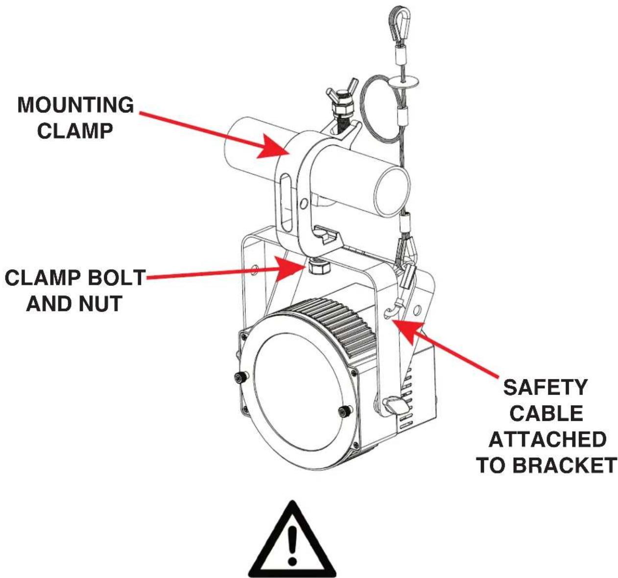
SAFETY CABLE:
ALWAYS ATTACH A SAFETY CABLE WHENEVER INSTALLING THIS FIXTURE IN A SUSPENDED ENVIRONMENT TO ENSURE THAT THE FIXTURE WILL NOT FALL IF THE CLAMP FAILS.
INSTALLATION
STAND MOUNTING
This unit can also be installed atop a tripod stand. Simply secure the Omega bracket to the bottom face of the device, then insert the threaded bolt on the top of the tripod stand through the hole in the Omega bracket. Tighten the nut onto the threaded bolt to secure the mounted device in place.
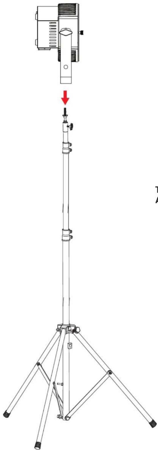
natural_image
Line drawing of a tripod-mounted surveying instrument with a red arrow indicating the downward motion (no text or symbols present)
CAUTION!
MAKE SURE THAT THE TRIPOD LEGS AND ALL TELESCOPING ELEMENTS OF THE TRIPOD STAND ARE LOCKED IN PLACE BEFORE INSTALLING THE DEVICE ATOP THE STAND!
POSITION THE TRIPOD STAND AND MOUNTED DEVICE ONLY ON FLAT, STABLE SURFACES! DEPLOY TRIPOD LEGS FULLY IN ORDER TO MAXIMIZE STABILITY!
INSTALLATION GUIDELINES
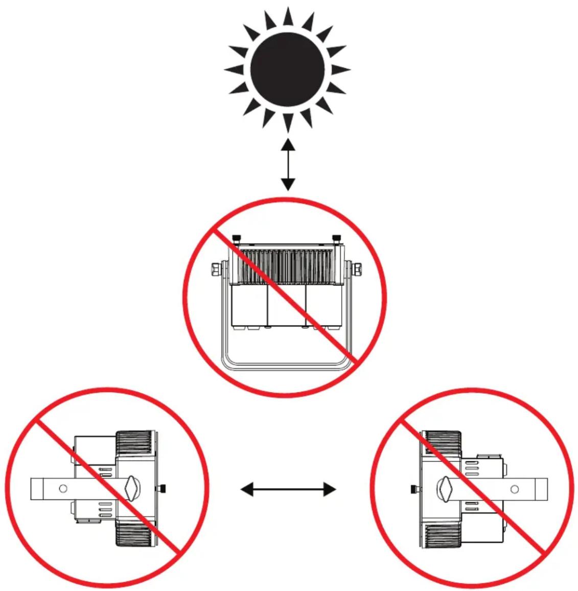
POTENTIAL INTERNAL FIXTURE DAMAGE FROM EXTERNAL SOURCES OF LIGHT BEAMS
External sources of light beams from direct sunlight, lighting moving head fixtures, and lasers, which are focused directly towards the exterior housing and/or penetrate the front lens opening of ADJ lighting fixtures, can cause severe internal damage including burning to optics, dichroic color filters, glass and metal gobos, prisms, animation wheels, frost filters, iris, shutters, motors, belts, wiring, discharge lamps, and LEDs.
This issue is not specific only to ADJ lighting fixtures, it is a common issue with lighting fixtures from all manufacturers. Although there is no true way to fully prevent this issue from happening, the guidelines below can prevent any potential damage from occurring if followed. Contact ADJ Service for more details.
DO NOT EXPOSE THE FIXTURE AND/OR FRONT LENS OPENING TO LIGHT BEAMS FROM DIRECT SUNLIGHT, OTHER LIGHTING MOVING HEAD FIXTURES, AND LASERS WHILE UNPACKING, INSTALLATION, USE, AND EXTENDED IDLE TIMES OUTDOORS. DO NOT FOCUS A LIGHT BEAM FROM ONE LIGHTING FIXTURE DIRECTLY TOWARDS ANOTHER.
flowchart
graph TD
    A["Sun"] --> B["No Radiation"]
    B --> C["Battery with Inverter"]
    C --> D["No Radiation"]
    D --> E["Battery with Inverter"]
    E --> F["No Radiation"]
INSTALLATION
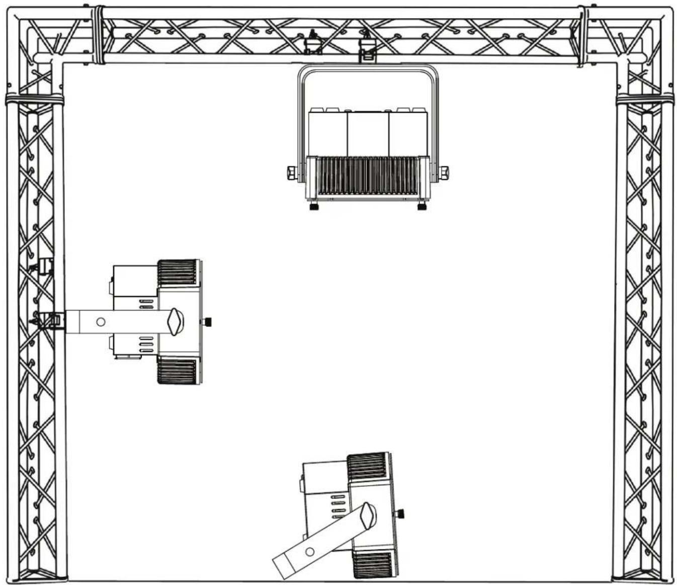
natural_image
Technical line drawing of a mechanical assembly with three views (top, front, side) showing structural components without any text or symbols.The unit is fully operational in three different mounting positions: hanging upside-down from the ceiling or trussing, sideways on trussing, or set on a flat level surface. Be sure this fixture is kept at least 12m (40ft) away from any flammable materials (decorations, etc). Always use and install a safety cable (not included) as a safety measure to prevent accidental damage and/or injury in the event the clamp fails. Never use the carrying handles for secondary attachment.

FALLING FIXTURES CAN CAUSE SEVERE INJURY OR SERIOUS EQUIPMENT DAMAGE! FOR THIS REASON, FIXTURES SHOULD BE INSTALLED AND INSPECTED ONLY BY QUALIFIED PERSONNEL. DO NOT INSTALL THE UNIT IF YOU LACK THE QUALIFICATIONS TO DO SO, OR IF YOU HAVE DOUBTS ABOUT THE SAFETY AND SECURITY OF THE INSTALLATION SETUP OR LOCATION!

ALWAYS ATTACH A SAFETY CABLE WHENEVER INSTALLING THIS FIXTURE IN A SUSPENDED ENVIRONMENT TO ENSURE THAT THE FIXTURE WILL NOT FALL IF THE CLAMP FAILS.
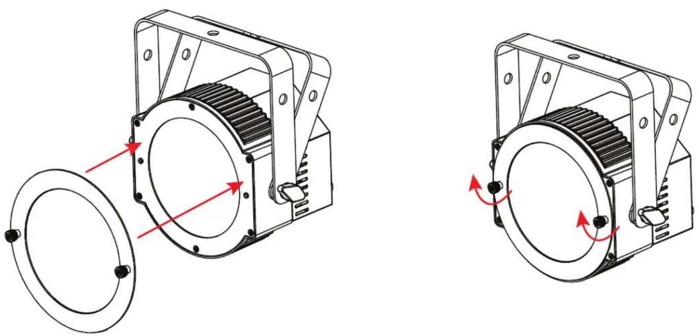
ACCESSORY INSTALLATION
FROST LENS
A removeable frost lens is included with the fixture. To install, insert the two thumb screws on the frost lens into the installation holes on the fixture lens frame, then tighten the thumb screws to secure the frost lens in place.
NOTE: In order for RDM to work properly, RDM enabled equipment must be used throughout the entire system, including DMX data splitters and wireless systems.
Remote Device Management (RDM) is a protocol that sits on top of the DMX512 data standard for lighting, allowing the DMX systems of the fixtures to be modified and monitored remotely. This protocol is ideal for instances in which a unit is installed in a location that is not easily accessible.
With RDM, the DMX512 system becomes bi-directional, allowing a compatible RDM enabled controller to send out a signal to devices on the wire, as well as allowing the fixture to respond (known as a GET command). The controller can then use its SET command to modify settings that would typically have to be changed or viewed directly via the unit's display screen, including the DMX Address, DMX Channel Mode, and Temperature Sensors.
FIXTURE RDM INFORMATION:
| RDM Code Device ID Device Model ID Personality ID | |||
| 1900 0000 | -FFFF 42 | 4Ch (1); 7Ch (2); 8Ch (3); 10Ch (4); 13Ch (5); 16Ch (6) | |
Please be aware that not all RDM devices support all RDM features, and therefore it is important to check beforehand to ensure that the equipment that you are considering includes all of the features that you require.
| [0x0200] Sensor Definition |
| [0x0201] Sensor Value |
| [0x0080] Device Model Description |
| [0x0081] Manufacturer Label |
| [0x0082] Device Label |
| [0x00E0] DMX Personality |
| [0x00E1] DMX Personality Description |
| [0x0400] Device Hours |
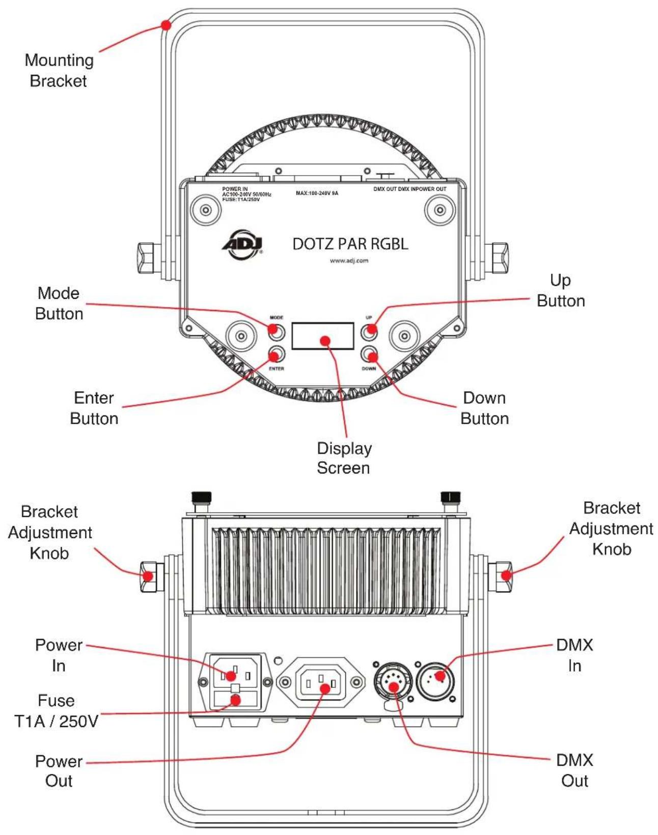
CONTROL PANEL
This unit features a display screen with a 4-button control pad, which can be used to easily adjust any device settings.
Pressing the MODE button will cycle through the various Main Menu options. When the desired Main Menu option is displayed on the screen, press the ENTER button to enter the sub-menu, then use the UP and DOWN buttons to scroll through sub-menu options. In some cases, there will be a second sub-menu that can be navigated in the same way.
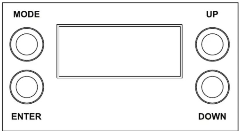
SCREEN LOCK
The control panel screen will lock after a period of inactivity which can be set by navigating to Personality > Display > Lock. Default time is 30 seconds. To unlock the screen, press and hold the MODE button for 3 seconds.
SYSTEM MENU
| DMX SET | Address 001 - 512 | Set DMX starting address | ||
| Ch. Mode | 4ch | Select DMX channel mode | ||
| 7ch | ||||
| 8ch | ||||
| 10ch | ||||
| 13ch | ||||
| 16ch | ||||
| No DMX | Hold | Fixture holds last configuration received before DMX signal was lost or interrupted | ||
| Blackout | Fixture takes all channels to 0 if DMX signal is lost or interrupted | |||
| Int Prog | Fixture defaults to internal program if DMX signal is lost or interrupted | |||
| PERSONALITY | Primary On / Off | Set fixture as a primary unit | ||
| Secondary On / Off | Set fixture as a secondary unit | |||
| Fan Set | Auto | Select fan settingH | ||
| Silent | ||||
| Dim Mode | Standard | Select dim mode and set dim speed | ||
| Stage | ||||
| TV | ||||
| Archi | ||||
| Theatre | ||||
| Stage 2 | ||||
| Dim Speed 0.1s - 10s | ||||
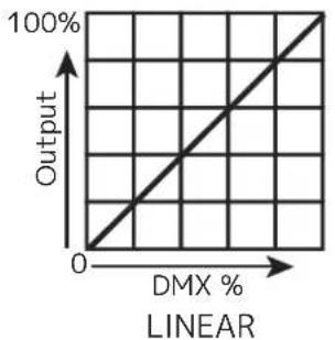
| Dim Curve | Square | Select dim curve | ||
| Linear | ||||
| Inv. Squa | ||||
| S. Curve | ||||
SYSTEM MENU
| PERSONALITY(continued) | Display | Save Dlay 1 - 10 | Screen turns off after selected period of inactivity | ||
| Lock Off, 1min - 10 | 0min | Screen locks after selected period of inactivity | |||
| Service Passcode = 050 | White Balance | Red 000 - 255 | Calibrate white balance | ||
| Green 000 - 255 | |||||
| Blue 000 - 255 | |||||
| Lime 000 - 255 | |||||
| S. Update Yes / No | Update fixture software | ||||
| Restore Yes / No | Returns fixture to default factory settings | ||||
| MANUAL | Red 000 - 255 | Manually set each parameter; Color Macros take priority over RGBL settings | |||
| Blue 000 - 255 | |||||
| Green 000 - 255 | |||||
| Lime 000 - 255 | |||||
| Clr Macro 00 - 64 | |||||
| Clr Temp 000 - 255 | |||||
| Clr Te Mac (color temp macros) | 000 - 255 | ||||
| Strobe 000 - 255 | |||||
| Mastr Dim 000 - 255 | |||||
| Auto Prog 000 - 255 | |||||
| Prog Spd 000 - 255 | |||||
| Prog Fade | 000 - 255 | ||||
| INT PROGS | Prog 0 | Speed 000 - 255 | Select and con-figure internal program settings | ||
| Fade | 000 - 255 | ||||
| Sound On / Off | 000 - 255 | ||||
| Prog 1 | Speed 000 - 255 | ||||
| Fade | 000 - 255 | ||||
| Sound On / Off | 000 - 255 | ||||
| ... | ... | ... | ... | ||
| Prog 7 | Speed 000 - 255 | ||||
| Fade | 000 - 255 | ||||
| Sound On / Off | 000 - 255 | ||||
SYSTEM MENU
| INFO | Hours | Pwr On Hr 1 xxxxxx Hours | Total lifetime hours that fixture has been powered on | ||
| Pwr On Hr 2 xxxxxx Hours | Hours fixture has been powered on since last reset | ||||
| Pwr On Rst Passcode = 050 | Reset Pwr On Hr 2 value | ||||
| Temp | xxx^ xxx^ F / xxx^ C | Display current temp reading | |||
| Max Temp 1 | xxx^ F / xxx^ C | Max recorded temp since last reset | |||
| Max Temp 2 | xxx^ F / xxx^ C | Lifetime max recorded temp | |||
| Temp Rst Yes / No | Passcode = 050 | Reset value for Max Temp 2 | |||
| Humidity xxx% | Display current humidity level | ||||
| Fan Info | Fan 1 RPM xxxx | Display current speed of fan 1 | |||
| Fan 2 RPM xxxx | Display current speed of fan 2 | ||||
| DMX Value | Red | Display current DMX value for each parameter | |||
| Green | |||||
| ... | |||||
| Auto Prog | |||||
| Soft Vers x.xx | Display current software version | ||||
DMX SET UP
DMX-512: DMX is short for Digital Multiplex. This is a universal protocol used as a form of communication between intelligent fixtures and controllers. A DMX controller sends DMX data instructions from the controller to the fixture. DMX data is sent as serial data that travels from fixture to fixture via the DATA "IN" and DATA "OUT" XLR terminals located on all DMX fixtures (most controllers only have a DATA "OUT" terminal).
DMX Linking: DMX is a language allowing all makes and models of different manufacturers to be linked together and operate from a single controller, as long as all fixtures and the controller are DMX compliant. To ensure proper DMX data transmission, try to use the shortest cable path possible when linking several DMX fixtures. The order in which fixtures are connected in a DMX line does not influence the DMX addressing. For example, a fixture assigned a DMX address of 1 may be placed anywhere in a DMX line: at the beginning, at the end, or anywhere in the middle. When a fixture is assigned a DMX address of 1, the DMX controller knows to send DATA assigned to address 1 to that unit, no matter where it is located in the DMX chain.
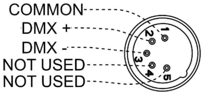
Data Cable (DMX Cable) Requirements (For DMX Operation): This unit can be controlled via DMX-512 protocol. The DMX address is set on the rear panel of the unit. Your unit and your DMX controller require a standard 5-pin XLR connector for data input and data output. We recommend Accu-Cable DMX cables. If you are making your own cables, be sure to use standard 110-120 Ohm shielded cable (This cable may be purchased at almost all pro lighting stores). Your cables should be made with a male XLR connector at one end and a female XLR connector at the other. Also remember that DMX cable must be daisy chained and cannot be split.
Notice: Be sure to follow fthe illustration below when making your own cables. Do not use the ground lug on the XLR connector. Do not connect the cable's shield conductor to the ground lug or allow the shield conductor to come in contact with the XLR's outer casing. Grounding the shield could cause a short circuit and erratic behavior.
DMX SET UP
Special Note: Line Termination. When longer runs of cable are used, you may need to use a terminator on the last unit to avoid erratic behavior. A terminator is a 110-120 ohm 1/4 watt resistor which is connected between pins 2 and 3 of a male XLR connector (DATA + and DATA -). This unit is inserted in the female XLR connector of the last unit in your daisy chain to terminate the line. Using a cable terminator (ADJ part number Z-DMX/T) will reduce the risk of erratic behavior.
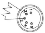

A DMX512 terminator reduces signal errors, avoiding most signal reflection interference. Connect PIN 2 (DMX-) and PIN 3 (DMX+) of the last fixture in series with a 120 Ohm, 1/4 W Resistor to terminate the DMX512.
DMX ADDRESSING.
All fixtures should be given a DMX starting address when using a DMX controller, so the correct fixture responds to the correct control signal. This digital starting address is the channel number from which the fixture starts to “listen” to the digital control signal sent out from the DMX controller. The assignment of this starting DMX address is achieved by setting the correct DMX address on the digital control display on the fixture.
You can set the same starting address for all fixtures or a group of fixtures, or set different addresses for each individual fixture. Setting all fixtures to the same DMX address will cause all fixtures to react in the same way. In other words, changing the settings of one channel will affect all the fixtures simultaneously.
If you set each fixture to a different DMX address, each unit will start to "listen" to the channel number you have set, based on the quantity of DMX channels of each fixture. That means changing the settings of one channel will only affect the selected fixture.
For example, when this unit is operating in 4 channel mode, you should set the starting DMX address of the first unit to 1, the second unit to 5 (1 + 4), the third unit to 9 (1 + 4 + 4), and so on. See the chart below for more details.
| CHANNEL MODE | UNIT 1 ADDRESS | UNIT 2 ADDRESS | UNIT 3 ADDRESS | UNIT 4 ADDRESS |
| 4Ch 1 5 9 13 | ||||
| 7Ch 1 8 15 22 | ||||
| 8Ch 1 9 17 25 | ||||
| 10Ch 1 11 21 31 | ||||
| 13Ch 1 14 27 40 | ||||
| 16Ch 1 17 33 49 |
DMX TRAITS
| CHANNEL | DMX VALUES | FUNCTION | |||||
| 4CH 7 | CH 8C | H 10CH | 13CH 1 | 6CH | |||
| 1 1 | 1 1 1 | 000 - 25 | 5 Red, 0 | - 100% | |||
| 2 00 | 0 - 255 | Red Fine | 16-bit | ||||
| 2 2 | 3 2 2 2 | 000 - 25 | 5 Green, | 0 - 100% | |||
| 4 00 | 0 - 255 | Green Fine | 16-bit | ||||
| 3 3 | 5 3 3 3 | 000 - 25 | 5 Blue, | 0 - 100% | |||
| 6 00 | 0 - 255 | Blue Fine | 16-bit | ||||
| 4 4 | 7 4 4 4 | 000 - 25 | 5 Lime, | 0 - 100% | |||
| 8 00 | 0 - 255 | Lime Fine | 16-bit | ||||
| 5 5 5 | 000 - 25 | 5 Color Macros, see Color Macros Chart section | |||||
| 6 6 6 | 000 - 25 | 5 Color Temperature, 2700 - 6500K Linear | |||||
| 7 7 7 | Color Temperature Macros | ||||||
| 000 Off | |||||||
| 001 - 054 2 | 700K | ||||||
| 055 - 109 3 | 200K | ||||||
| 110 - 164 4 | 000K | ||||||
| 165 - 219 5 | 600K | ||||||
| 220 - 255 6 | 500K | ||||||
| 5 8 8 8 | Shutter, Strobe | ||||||
| 000 - 031 | LEDs Off | ||||||
| 032 - 063 | LEDs On | ||||||
| 064 - 095 | Strobe Effect, slow to fast | ||||||
| 096 - 127 | LEDs On | ||||||
| 128 - 159 | Pulse Effect in Sequences | ||||||
| 160 - 191 | LEDs On | ||||||
| 192 - 223 | Random Strobe Effect, slow to fast | ||||||
| 224 - 255 | LEDs On | ||||||
| 6 9 9 | 9 000 | - 255 Dimmer Intensity, | 0 - 100% | ||||
| 7 | 10 | 10 | 10 | 000 - 255 | Dimmer Fine 16-bit | ||
| 11 | Auto Programs | ||||||
| 000 - 031 | Off | ||||||
| 032 - 063 | Program 1 | ||||||
| 064 - 095 | Program 2 | ||||||
| 096 - 127 | Program 3 | ||||||
| 128 - 159 | Program 4 | ||||||
| 160 - 191 | Program 5 | ||||||
| 192 - 223 | Program 6 | ||||||
| 224 - 255 | Program 7 | ||||||
| 12 | 000 - 255 | Auto Programs Speed, slow to fast | |||||
| 13 | 000 - 255 | Auto Programs Fade, least to most | |||||
DMX TRAITS
| CHANNEL | DMX VALUES | FUNCTION | |||||
| 4CH | 7CH | 8CH | 10CH | 13CH | 16CH | ||
| 11 14 | Dim Mode | ||||||
| 000 - 020 Default to Unit Setting | |||||||
| 021 - 040 Standard | |||||||
| 041 - 060 Stage | |||||||
| 061 - 080 TV | |||||||
| 081 - 100 Architectural | |||||||
| 101 - 120 Theatre | |||||||
| 121 - 140 Stage 2 | |||||||
| 141 - 160 Dim Speed, 0.1s to 10s | |||||||
| 161 - 255 Default to Unit Setting | |||||||
| 12 15 | Dim Curves | ||||||
| 000 - 020 Square | |||||||
| 021 - 040 Linear | |||||||
| 041 - 060 Inv. Squa | |||||||
| 061 - 080 S. Curve | |||||||
| 081 - 255 No Function | |||||||
| 13 16 | Special Functions | ||||||
| 000 - 015 Default to Unit Setting | |||||||
| 016 - 030 900 Hz | |||||||
| 031 - 045 1000 Hz | |||||||
| 046 - 060 1100 Hz | |||||||
| 061 - 075 1200 Hz | |||||||
| 076 - 090 1300 Hz | |||||||
| 091 - 105 1400 Hz | |||||||
| 106 - 120 1500 Hz | |||||||
| 121 - 135 2500 Hz | |||||||
| 136 - 150 4000 Hz | |||||||
| 151 - 165 5000 Hz | |||||||
| 166 - 180 10000 Hz | |||||||
| 181 - 195 15000 Hz | |||||||
| 196 - 210 20000 Hz | |||||||
| 211 - 225 25000 Hz | |||||||
| 226 Auto Fan (hold 5 sec) | |||||||
| 227 High Fan (hold 5 sec) | |||||||
| 228 Silent Fan (hold 5 sec) | |||||||
| 229 - 255 No Function | |||||||
COLOR MACROS CHART
| MACRO NO. | DMX VALUES RED GREEN BLUE LIME | ||||
| Off 000 0 | 0 0 0 | ||||
| 1 001 - 0 | 04 80 255 234 80 | ||||
| 2 005 - 0 | 08 80 255 164 80 | ||||
| 3 009 - 0 | 12 77 255 112 77 | ||||
| 4 013 - 0 | 16 117 255 83 83 | ||||
| 5 017 - 0 | 20 160 255 77 77 | ||||
| 6 021 - 0 | 24 223 255 83 83 | ||||
| 7 025 - 0 | 28 255 243 77 77 | ||||
| 8 029 - 0 | 32 255 200 74 74 | ||||
| 9 033 - 0 | 36 255 166 77 77 | ||||
| 10 | 037 - 040 | 255 125 | 74 74 | ||
| 11 | 041 - 044 | 255 | 97 | 77 | 74 |
| 12 | 045 - 048 | 255 71 | 77 71 | ||
| 13 | 049 - 052 | 255 83 | 134 83 | ||
| 14 | 053 - 056 | 255 93 | 182 93 | ||
| 15 | 057 - 060 | 255 96 | 236 96 | ||
| 16 | 061 - 064 | 238 93 | 255 93 | ||
| 17 | 065 - 068 | 196 87 | 255 87 | ||
| 18 | 069 - 072 | 150 90 | 255 90 | ||
| 19 | 073 - 076 | 100 77 | 255 77 | ||
| 20 | 077 - 080 77 | 100 255 77 | |||
| 21 | 081 - 084 67 | 148 255 67 | |||
| 22 | 085 - 088 77 | 195 255 77 | |||
| 23 | 089 - 092 77 | 234 255 77 | |||
| 24 | 093 - 096 | 158 255 | 144 | 144 | |
| 25 | 097 - 100 | 255 251 | 153 | 153 | |
| 26 | 101 - 104 | 255 175 | 147 | 147 | |
| 27 | 105 - 108 | 255 138 | 186 | 138 | |
| 28 | 109 - 112 | 255 147 | 251 | 147 | |
| 29 | 113 - 116 | 151 138 | 255 | 138 | |
| 30 | 117 - 120 | 99 | 0 | 255 | 100 |
| 31 | 121 - 124 | 138 169 | 255 | 138 | |
| 32 | 125 - 128 | 255 255 | 255 | 255 | |
| 33 | 129 - 132 | 255 206 | 143 0 | ||
| 34 | 133 - 136 | 254 177 | 153 0 | ||
| 35 | 137 - 140 | 254 192 | 138 0 | ||
| 36 | 141 - 144 | 254 165 | 98 | 0 | |
| 37 | 145 - 148 | 254 121 | 0 0 | ||
| 38 | 149 - 152 | 176 17 0 0 | |||
COLOR MACROS CHART
| MACRO NO. | DMX VALUE RED | GREEN BLUE LIME | ||
| 39 153 - 1 | 56 96 0 11 0 | |||
| 40 157 - 1 | 60 234 139 171 0 | |||
| 41 161 - 1 | 64 224 5 97 0 | |||
| 42 165 - 1 | 68 175 77 173 0 | |||
| 43 169 - 1 | 72 119 1 | 30 199 0 | ||
| 44 173 - 1 | 76 147 164 212 0 | |||
| 45 177 - 1 | 80 88 2 163 0 | |||
| 46 181 - 1 | 84 0 38 | 86 0 | ||
| 47 185 - 1 | 88 0 142 | 208 0 | ||
| 48 189 - 1 | 92 52 148 209 0 | |||
| 49 193 - 1 | 96 1 134 | 201 0 | ||
| 50 197 - 2 | 00 0 145 | 212 0 | ||
| 51 201 - 2 | 04 0 121 | 192 0 | ||
| 52 205 - 2 | 08 0 129 | 184 0 | ||
| 53 | 209 - 212 | 0 | 83 | 115 0 |
| 54 213 - 2 | 16 0 97 | 166 0 | ||
| 55 217 - 2 | 20 1 100 | 167 0 | ||
| 56 221 - 2 | 24 0 40 | 86 0 | ||
| 57 225 - 2 | 28 209 219 182 0 | |||
| 58 229 - 2 | 32 42 165 85 0 | |||
| 59 233 - 2 | 36 0 46 | 35 0 | ||
| 60 237 - 2 | 40 8 107 | 222 0 | ||
| 61 241 - 2 | 44 255 0 | 0 0 | ||
| 62 245 - 2 | 48 0 255 | 0 0 | ||
| 63 249 - 2 | 52 0 | 0 255 0 | ||
| 64 253 - 2 | 55 0 | 0 | 0 255 |
DIM SPEEDS
| DMX VALUES DELAY TIME | |
| 121 0.1 sec | |
| 122 0.2 sec | |
| 123 0.3 sec | |
| 124 0.4 sec | |
| 125 0.5 sec | |
| 126 0.6 sec | |
| 127 0.7 sec | |
| 128 0.8 sec | |
| 129 0.9 sec | |
| 130 1.0 sec | |
| 131 1.5 sec | |
| 132 2.0 sec | |
| 133 3.0 sec | |
| 134 4.0 sec | |
| 135 5.0 sec | |
| 136 6.0 sec | |
| 137 7.0 sec | |
| 138 8.0 sec | |
| 139 9.0 sec | |
| 140 10.0 sec | |
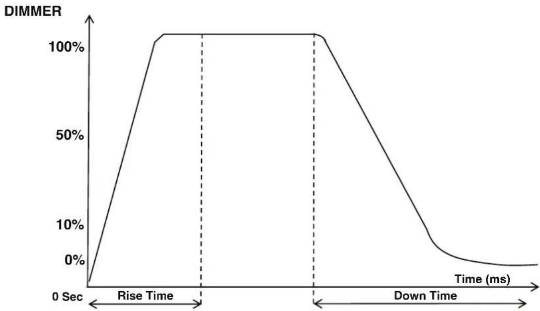
DIM MODES
line
| Time (ms) | DIMMER | | --------- | ------ | | 0 | 0% | | Rise | 100% | | Down | 0% || Dimming Curve Ramp Effect | 0 sec Fade Time | 1 sec Fade Time | ||
| 0 | 255 | 0 | 255 | |
| Rise Time (ms) | Down Time (ms) Rise | Time (ms) Down Time (ms) | ||
| Standard (default) 0 | 0 0 0 | |||
| Stage 780 1100 1540 | 1660 | |||
| TV 1180 1520 1860 | 1940 | |||
| Architectural 1380 | 1730 2040 2120 | |||
| Theatre 1580 1940 | 2230 2280 | |||
| Stage 2 0 1100 0 1660 | ||||
line
| DMX % | Output | |-------|--------| | 0 | 0 | | 100 | 100 |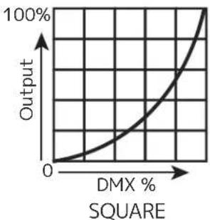
line
| DMX % | Output | |-------|--------| | 0 | 0 | | 50 | 50 | | 100 | 100 |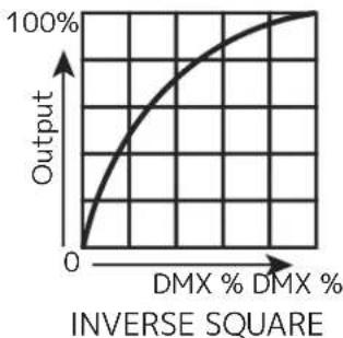
line
| DMX % | Output | |-------|--------| | 0 | 0 | | > DMX % | 100% |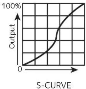
line
| S-Curve | Output | | ------- | ------ | | 0 | 0 | | >0 | 100% |PRIMARY-SECONDARY SET UP
This function allows you to link units together to run in a Primary-Secondary set-up, in which one unit will act as the controlling unit and the others will react to the controlling unit's built-in programs. Any unit can be configured to act as a Primary or as a Secondary, but only one unit in a given system can be programmed to act as the Primary.
Primary-Secondary Connections and Settings:
- Daisy chain your units via the XLR connectors on the rear panels of each unit. Use standard XLR data cables to link your units together. Remember that the male XLR connector is the input and the female XLR connector is the output. The first unit in the chain (primary) will use the female XLR connector only. The last unit in the chain will use the male XLR connector only.
- On the unit that you want to designate as the primary, use the display screen and control panel to navigate to Personality > Primary. Select this sub-menu using the ENTER button, and use the UP and DOWN buttons to set this to ON. Press SETUP to confirm your selection, then configure the unit's operation as desired.
- On the units that you want to designate as secondaries, use the display screen and control panel to navigate to Personality > Secondary. Select this sub-menu using the ENTER button, and use the UP and DOWN buttons to set this to ON. Press SETUP to confirm your selection. Make sure that only one unit is designated as the Primary, while all other units are designated as Secondaries.
- The secondary units will now follow the behavior of the primary unit.
NOTES:
- Only one unit should be configured as the primary, while all the other units should be configured as secondaries.
- All units should be set to the same DMX channel mode.
- If fixtures fail to sync, verify that all settings mentioned above are the same, then power all devices off, then switch them on again to re-establish the link.
MULTI UNIT POWER LINKING
This features allows you to connect the fixtures to one another using the power cable input and output sockets.
The maximum number of units that can be linked in this manner is as follows:
• 29 units when running on 120V power.
• 49 units when running on 230V power.
DO NOT EXCEED THIS MAXIMUM NUMBER WHEN POWER LINKING UNITS!
All linked units must be of the same make and model type. Do not mix and match units!
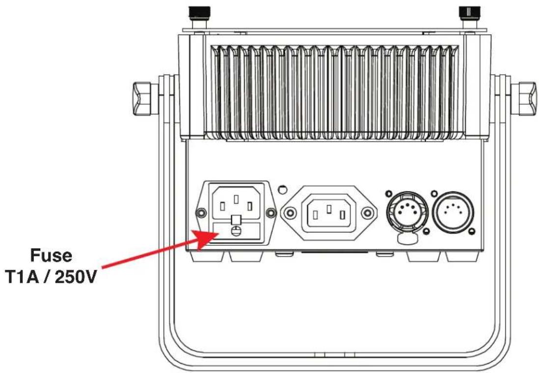
FUSE REPLACEMENT
Disconnect the unit from its power source. Locate the fuse holder, which is beside the power port on the top of the unit, as shown in the diagram below. Use the flat head screwdriver to gently remove the fuse holder, then remove the used fuse and install a fresh fuse in its place. Always use a fuse of the same T1A / 250V rating for replacement.
MAINTENANCE GUIDELINES

DISCONNECT POWER BEFORE PERFORMING ANY MAINTENANCE!
CLEANING
Frequent cleaning is recommended to ensure proper function, optimized light output, and an extended life. The frequency of cleaning depends on the environment in which the fixture operates: damp, smoky, or particularly dirty environments can cause greater accumulation of dirt on the fixture's optics. Clean the external lens surface regularly with a soft cloth to avoid dirt/debris accumulation.
NEVER use alcohol, solvents, or ammonia-based cleaners.
MAINTENANCE
Regular inspections are recommended to ensure proper function and extended life. There are no user serviceable parts inside this fixture. Please refer all other service issues to an authorized ADJ service technician. Should you need any spare parts, please order genuine parts from your local ADJ dealer.
Please refer to the following points during routine inspections:
A. A detailed electrical check by an approved electrical engineer every three months, to make sure the circuit contacts are in good condition and prevent overheating.
B. Be sure all screws and fasteners are securely tightened at all times. Loose screws may fall out during normal operation, resulting in damage or injury as larger parts could fall.
C. Check for any deformations on the housing, color lenses, rigging hardware, and rigging points (ceiling, suspension, trussing). Deformations in the housing could allow for dust to enter into the fixture. Damaged rigging points or unsecured rigging could cause the fixture to fall and seriously injure a person(s).
D. Electric power supply cables must not show any damage, material fatigue, or sediments.
NEVER remove the ground prong from the power cable.
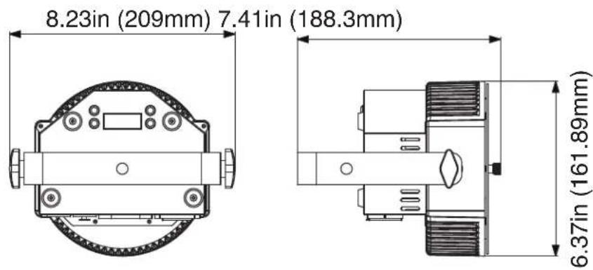
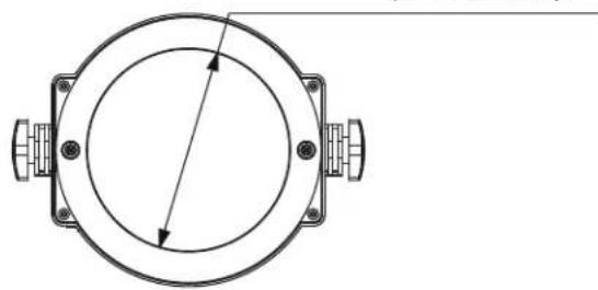
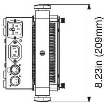
DIMENSIONAL DRAWINGS
∅ 4.72in
(∅ 120mm)
natural_image
Technical diagram of a circular mechanical component with mounting flanges and central shaft (no text or symbols)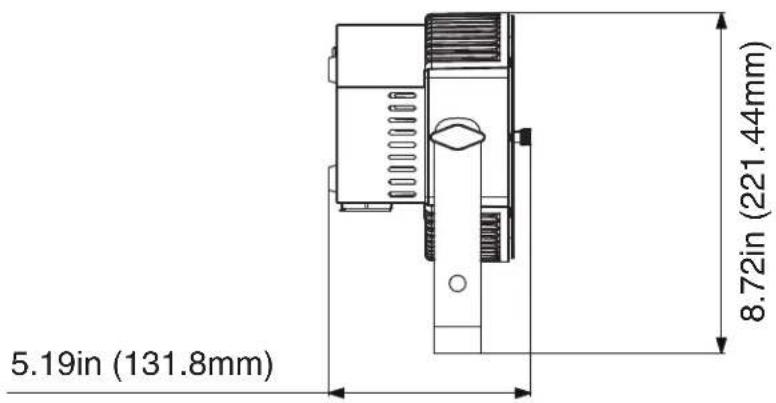
SPECIFICATIONS
SOURCE:
• Light Source: 16 x 3.5-Watt RGBL C.O.B. LED (4-IN-1: Red, Green, Blue & Lime)
• 20,000 Hours Rated Life
PHOTOMETRIC DATA:
• CRI: TBA
• CRI R9: TBA
- Lumens: 1250
EFFECTS:
- 35^ Beam Angle
• Linear Color Temperature Control (2700K to 6500K) - Preset Color Temperatures
• 16-Bit Fine Color Control (Red, Green, Blue & Lime)
• 64 built-in Color Macros
CONTROL:
• 4-button, DMX digital display on rear panel
- 6 Operational modes: Static Color Mode, RGBL Dimmer Mode, Program Mode, Sound Active Mode, Wireless RF and DMX Controlled
• Supports RDM (Remote Device Management)
• With Wired Digital Communication Network
- 6 selectable Dimming Modes (Standard, Stage, TV, Architectural, Theatre & Stage 2)
- 4 selectable Dim Curves (Linear, Square Inv. Squa, S-Curve)
• 1200Hz LED Refresh Rate
• LED pulse and strobe effect
• Electronic Dimming: 0 - 100%
CONSTRUCTION / CONNECTIONS:
- Plastic construction
• IEC Locking, In/Out Power connectors - Indoor 5-pin, XLR DMX, In/Out sockets
- Scissor Yoke
ELECTRICAL / THERMAL:
• Multi-voltage operation: AC 100-240V, 50/60Hz
• Max Power LInk: 30 @120V., 57 @230V.
• Max power consumption: 36W
- Fuse protected: T1A/250V (5*20mm)
DIMENSIONS / WEIGHT:
• Length: 5.19" (131.8mm)
- Width: 8.23" (209mm)
• Height: 8.72" (221.44mm)
• Weight: 4.41lbs. / 2kg.
APPROVALS / RATINGS:
Please Note: Specifications and improvements in the design of this unit and this manual are subject to change without any prior written notice.
This page intentionally left blank.