
EasyIP Ecosystem Base Kit - Video Conferencing System Vaddio - Free user manual and instructions
Find the device manual for free EasyIP Ecosystem Base Kit Vaddio in PDF.

| Product Type | AV-over-IP Video Conferencing System (Base Kit includes EasyIP Decoder, EasyIP Mixer, EasyIP 10/20 Cameras, cables, remote) |
| Brand | Vaddio (Legrand AV Inc.) |
| Model | EasyIP Ecosystem Base Kit (999-60210-000 Decoder, 999-60320-000 Mixer, 999-30200-000/999-30230-000 Cameras) |
| Power Supply | PoE+ (IEEE 802.3at) via network switch; each device requires PoE+ power. |
| Video Resolution | Up to 1080p/60 uncompressed USB 3.0 streaming; HDMI output up to 1080p. |
| Audio Capabilities | Full-duplex audio; EasyIP Decoder: 2 EasyMic inputs + speaker output; EasyIP Mixer: 2 analog mic/line inputs, 2 line outputs, Dante connectivity for up to 4 microphones/speakers. |
| Camera Control | Up to 4 EasyIP PTZ cameras per host; pan/tilt/zoom via web interface, IR remote, or Telnet; presets and CCU scenes (EasyIP 20). |
| USB Streaming | UVC/UAC compliant; plug-and-play with conferencing apps; USB 3.0 Type B connector. |
| Network Connectivity | RJ-45 10/100/1000 Mbps; automatic camera discovery on same subnet; HTTPS web interface. |
| Remote Management | Web interface, Vaddio Deployment Tool, Vaddio Device Controller; Telnet API for integration. |
| Included Accessories | EasyIP Decoder, EasyIP Mixer, EasyIP 10 and/or 20 cameras (qty varies), IR remote, Cat-5e cables, USB 3.0 cable, Phoenix connectors, wall mounts, Quick-Start Guide. |
| Dimensions (Decoder) | Approx. 8.5 x 5.2 x 1.7 in (216 x 132 x 43 mm) – half-rack width. |
| Dimensions (Mixer) | Approx. 8.5 x 5.2 x 1.7 in (216 x 132 x 43 mm) – half-rack width. |
| Dimensions (Camera) | EasyIP 10: about 6.7 x 5.5 x 5.5 in (170 x 140 x 140 mm) with mount; EasyIP 20: slightly larger. |
| Weight (Decoder) | Approx. 1.5 lb (0.68 kg). |
| Weight (Mixer) | Approx. 1.5 lb (0.68 kg). |
| Weight (Camera) | EasyIP 10: about 3.5 lb (1.6 kg); EasyIP 20: about 4.0 lb (1.8 kg). |
| Operating Temperature | 32 to 104°F (0 to 40°C). |
| Storage Temperature | -4 to 140°F (-20 to 60°C). |
| Safety & Compliance | FCC Part 15 Class A, ICES-003, CE, RoHS; indoor use only. |
| Maintenance | Firmware updates via web interface; factory reset via button or web; camera recalibration available. |
| Warranty | Standard Vaddio warranty; contact support for details. |
| Spare Parts / Reparability | Not user-serviceable; contact Vaddio for replacement units or professional repair. |
| General Information | Part of the EasyIP ecosystem; designed for conference rooms, classrooms, and professional AV environments; requires PoE+ switch (not included). |
Frequently Asked Questions - EasyIP Ecosystem Base Kit Vaddio
User questions about EasyIP Ecosystem Base Kit Vaddio
0 question about this device. Answer the ones you know or ask your own.
Ask a new question about this device
Download the instructions for your Video Conferencing System in PDF format for free! Find your manual EasyIP Ecosystem Base Kit - Vaddio and take your electronic device back in hand. On this page are published all the documents necessary for the use of your device. EasyIP Ecosystem Base Kit by Vaddio.
USER MANUAL EasyIP Ecosystem Base Kit Vaddio
natural_image
Product photo of vaddi audio recording equipment including a video player, a Easy5+ Encoder, and a Vaddi-branded device (no visible text or symbols on main components)Complete Manual for
EasyIP Systems
Featuring the EasyIP Decoder, EasyIP Mixer, and EasyIP Cameras
Document 411-0041-35 Rev D July 2020
Contents
Overview .1....
What's in this Guide.2....
The EasyIP Ecosystem.2....
EasyIP Decoder 2
EasyIP Mixer.2
EasyIP Cameras.2
EasyIP Switch.2
EasyIP Decoder Features 3.
EasyIP Mixer Features.3....
EasyIP 10 Camera Features.3
EasyIP 20 Camera Features.3....
Unpacking the EasyIP System Components 4
EasyIP Decoder AV-over-IP Switching USB Endpoint 4
EasyIP Mixer AV Switcher 4
EasyIP 10 AV-over-IP PTZ Camera 5
EasyIP 20 AV-over-IP PTZ Camera....6
A Quick Look at the EasyIP Family 7
EasyIP Decoder 7
Front View 7
Back View 7
EasyIP Mixer 8
Front View 8
Back View 8
EasyIP 10 Camera.9....
Front View....9
Back View 9
EasyIP 20 Camera....10
Front View.... 10
Back View 10
Installation 11
Don't Void Your Warranty! 11
Before You Start.... 11
Before Installing Cameras.... 12
Cabling Notes.... 12
RS-232 Serial Communication Settings and Port Pin-outs 13
EasyIP Mixer 13
EasyIP 20 Camera....14
Basic Connections - EasyIP Decoder 15
Basic Connections - EasyIP Mixer 16
Basic Connections – EasyIP Mixer with HDMI Input from EasyIP 20 Camera .....17
Installing the Wall Mount for the Camera 18....
Installing the Camera 19.
About Ceiling-Mounted Cameras 19
Powering Up the EasyIP System 20
Initial Set-Up and Access to Administrative Controls 21.
Browser Support 21......
Initial Device Set-up Process Overview 22
About the Vaddio Device Controller 22
About the Vaddio Deployment Tool 22
Access and Initial Device Set-Up Using the Vaddio Device Controller 23
Initial Device Set-Up and Access Using the Vaddio Deployment Tool 24
Manual Access and Initial Device Set-Up 25
Initial Access to the Web Interface 25
Access the Web Interface of an EasyIP Decoder or EasyIP Mixer Manually.... 26
Access the Web Interface of an EasyIP Camera Manually 27
Next Steps for New Deployments.... 28
Web Interface Quick Reference 29
EasyIP Decoder Basic Operation – Operator's Pages 29
EasyIP Mixer Basic Operation - Operator's Pages 29
System Administration (All Devices) 29
System Behaviors and Operation 30
Maintenance and Troubleshooting 30
System Administration.... 31
Setting Passwords and Access 31
Configuring Other Security Settings 32
Changing Device Hostnames 33
Specifying Time Zone and NTP Server 33
Adding Room Information to the Device's Web Interface 34
Pairing EasyIP Devices 35
Locating and Pairing to Cameras on the Network - EasyIP Decoder 35
Locating and Pairing to Cameras on the Network – EasyIP.Mixer 37
Unpairing Cameras 39
Using Dante Devices with the EasyIP Mixer 40
Locating and Pairing to Dante Devices 41
Pairing to More than Two EasyIP or Other Dante Microphones 43
About Channels and Flows 43
Creating a Multicast Flow 44
Combining Microphone Channels into Flows 45
Configuring System Behavior 47
Configuration Quick Reference 47
Configuring Streaming Behavior.... 48
Viewing a Stream 48
Configuring USB Streaming 48
Configuring the USB Stream Format for Specific Applications 49
Configuring Audio Settings.50
Muting All Audio Inputs Together 50
Muting and Controlling Volume Per Input or Output 51
Enabling Phantom Power to Microphones - EasyIP Mixer.52....
About Echo Cancellation 52
Fine-Tuning Microphone Performance - EasyIP Decoder 53
Fine-Tuning Microphone Performance - EasyIP Mixer 54
Presentation Adjustments.54
Performance Adjustments 55
About the Vaddio Dante Interface Application 56
Fine-Tuning EasyIP Microphone Performance 57
Fine-Tuning Speaker Performance - EasyIP Decoder 59
Fine-Tuning Speaker Performance – EasyIP Mixer 60
Synchronizing Audio with Video in the USB Stream – EasyIP_Mixer 61
Routing Audio - EasyIP Mixer 62
Working with Video - EasyIP Decoder 64
Working with Video - EasyIP Mixer 65
Working with the EasyIP Mixer's Video Inputs 65
Configuring the EasyIP Mixer's Video Output 66
Working with Graphics - EasyIP Mixer 66
Setting up Macros and Triggers 69
Writing and Editing Macros.... 70
Testing Macros 71
Assigning Macros to Triggers.... 73
Testing Triggers 74
Example: Assigning a Function to the Connected Microphone's Home Button .....74
Locking the Front Panel Controls - EasyIP Mixer 75
Configuring System Standby Behaviors 75
Configuring and Adjusting Cameras.... 76
Signal-Related Settings 77
Inverting the Image for Ceiling-Mounted Cameras 78
Setting Cameras to Respond to Different Frequencies 78.
Selecting the Camera to Control with the Remote 79
Indicator Light Behavior 79
Setting the Home Position and Other Preset Shots 79
Renaming Presets 81
Initial Lighting and Color Settings - EasyIP.20 82
Color and Image Quality Adjustments 83
Complete Manual for EasyIP Systems
Saving Color and Lighting Settings - EasyIP 20.84
Lighting and Image Quality Quick Reference 85....
Color Adjustment Quick Reference 86
Setting the Speeds for Manual Camera Movements.87....
Setting the Speeds of Camera Movements to Presets 87....
Setting the Speed for Tri-Synchronous Motion to Presets (EasyIP 20. Only).88....
Setting the Direction for Camera Movements 88....
Adjusting the Focus 89
Setting HDMI Video Output Resolution – EasyIP 20 Camera 90......
System Maintenance....91
Saving (Exporting) or Restoring (Importing) a Configuration.... 92
Installing a Firmware Update 93
Installing a Firmware Update for a Connected Vaddio EasyMIC Series Microphone – EasyIP
Decoder 94
Installing a Firmware Update for an EasyIP Microphone 95
Rebooting the Device 96
Using the Camera's Remote Control 97
Quick Reference 97
IR Remote Details 98
Storing a Preset Using the Remote 98
Clearing a Preset Using the Remote 98
Selecting the Camera to Control with the Remote 99
Using the Operator's Web Interface 100
Quick Steps: Muting and Standby 101
Moving the Camera to a Preset Position 102
Moving the Camera Manually 103
Working with Audio - EasyIP Decoder 104
Working with Audio - EasyIP Mixer 105
Selecting a PIP Source and Layout - EasyIP Mixer 106
Working with On-Screen Graphics - EasyIP Mixer 107
Serial Command API 109
Camera Commands for Cameras and Host Devices 110
camera home 110
camera pan 111
camera tilt 112
camera zoom 113
camera focus 114
camera preset 115
camera ccu get 116
camera ccu set 117
camera ccu scene 118
Complete Manual for EasyIP Systems
camera standby 119
Camera Commands Direct to Cameras Only 120
camera ptz-position_120
camera led 121
camera icr_121
Video Management Commands.122
video mute 122
video pip.123....
video source 123
video type 124
Audio Management Commands.125....
Audio Channels Available on the EasyIP Decoder 125
Audio Channels Available on the EasyIP Mixer 126
audio mute 127
audio volume 127
audio route.... 128
audio crosspoint-gain 128
Communication and Network Commands 129
camera authenticate 129
camera comm host 129
streaming settings get 130
network settings get.... 130
Control and Power Commands 131
trigger 131
camera standby_131
system standby 132
Maintenance and Troubleshooting Commands 133
camera recalibrate 133
network ping.133
system reboot....134
system factory-reset.... 134
version 135
Telnet Information and Session Management Commands 136
history 136
help 136
exit 136
RS-232 Serial Commands for EasyIP 20 Cameras 137
Camera Movement, Zoom, and Focus Commands 137
Movement, Zoom, and Focus Inquiry Commands 139
Color and Light Management Commands 140
Color and Light Management Inquiry Commands.... 141
Shutter Speed Values (CAM_Shutter) 142
Iris Values (CAM_Iris).143.
Iris Gain and Gain Limit Values (CAM_Gain) 143
Other Commands 144
Other Inquiry Commands 144
Specifications 145
EasyIP Decoder_145
EasyIP Mixer 146
Camera Specifications 147
Troubleshooting and Care 149
System and Power issues 149
Camera 150
Audio 151
Status Indicator Light 151
Correct a Camera Motor Calibration Error 151
Restoring Factory Default Settings.... 153
Contacting Vaddio Technical Support 154
Viewing Diagnostic Logs.... 154
Operation, Storage, and Care 155
Glossary 156
Compliance and Conformity Statements 160
FCC Part 15 Compliance 160
ICES-003 Compliance 160
European Compliance 161
Photo Credits....162
Index 163
Overview
This guide discusses the following products:
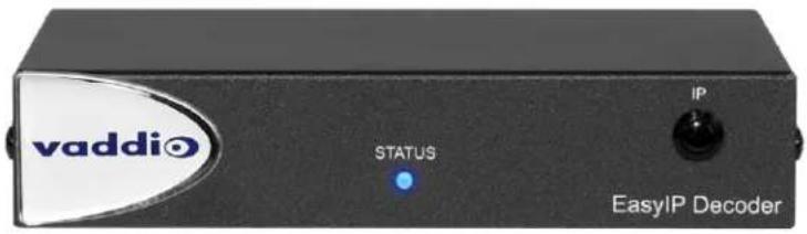
■ EasyIP Decoder AV-over-IP switching USB endpoint, 999-60210-000 (worldwide)
■ EasyIP Mixer AV switcher, 999-60320-000 (worldwide)

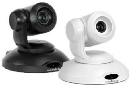
■ EasyIP 10 AV-over-IP PTZ camera, 999-30200-000 (black, worldwide) EasyIP 10 AV-over-IP PTZ camera, 999-30200-000W (white, worldwide)
natural_image
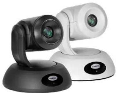
Two VDDI 2 video camera units shown from different angles (black and white) against a plain background, no text or symbols visible.■ EasyIP 20 AV-over-IP PTZ camera, 999-30230-000 (black, worldwide) EasyIP 20 AV-over-IP PTZ camera, 999-30230-000W (white, worldwide)
natural_image
Exterior view of a modern automated camera with dual lenses and a base-mounted display (no visible text or symbols)What's in this Guide
This guide covers
■ Unpacking
■ Physical features
■ Installation
■ System administration and performance/behavior configuration
■ Telnet API reference
■ Specifications
■ Troubleshooting
■ Warranty and compliance/conformity information
For your convenience, the information you need to install EasyIP products is available in the smaller, stand-alone Installation Guide for EasyIP AV-over-IP Systems.
The EasyIP Ecosystem
Vaddio® EasyIP products are designed to be used together, and have limited or no compatibility with other types of products.
■ EasyIP cameras deliver video in Vaddio's proprietary EasyIP format.
- An EasyIP host device (EasyIP Decoder or EasyIP Mixer) is required to convert the cameras' output signal to an IP and/or USB stream.
■ Only paired EasyIP cameras can be controlled by the EasyIP host device.
■ EasyIP host devices automatically detect EasyIP cameras on its own subnet.
■ Cameras are not required to be on the same subnet as the device that manages them.
■ EasyIP products require PoE+ power. Typically the EasyIP system is powered by a PoE+ switch.
EasyIP Decoder
The decoder is the central component of a basic EasyIP installation. Its functions include
■ Video – pair with up to four cameras at a time, control the active camera via web interface, and decode the camera's AV-over-IP signal.
■ Audio – connect two EasyMic microphones (CeilingMIC or TableMIC) and a speaker.
- USB streaming – configure for UVC-compliant or client-custom USB streaming for conferencing applications.
EasyIP Mixer
The mixer is the central component of a full-featured EasyIP pro AV room solution. Its functions include
■ Video – pair with up to four cameras at a time, control the active camera via web interface, and decode the camera's AV-over-IP signal.
■ Audio – two balanced audio inputs and outputs; pair with data products on your network – including up to four EasyIP microphones. Built-in audio mixer.
- USB streaming – configure for UVC-compliant or client-custom USB streaming for conferencing applications.
EasyIP Cameras
EasyIP cameras may be installed anywhere on the network. They require only a PoE+ power connection. An EasyIP Decoder or EasyIP Mixer is needed as a host device to decode the AV-over-IP signal.
Each camera may be paired to two host devices.
EasyIP Switch
A PoE+ switch simplifies installation, eliminating the need for PoE+ power injectors and placing all the connected products on the same subnet.
EasyIP Decoder Features
■ Uncompressed USB 3.0 streaming
■ Streaming video resolutions up to 1080p/60
■ Full-duplex audio streaming
■ Audio inputs for two Vaddio EasyMic microphones
■ HDMI video output for local display
■ Universal Video Class (UVC) and Universal Audio Class (UAC) drivers supported in ^® , Windows macOS ^® , and Linux operating systems, compatible with most UC conferencing applications
■ Integration-ready Telnet control
■ Pairs with up to four EasyIP 10 cameras on your network to provide control and manage streaming
■ Enterprise-class IT administrative capabilities with full web controls for remote management
EasyIP Mixer Features
■ Uncompressed USB 3.0 streaming
■ Streaming video resolutions up to 1080p/60
■ Full-duplex audio streaming
■ Line-level inputs for two microphones
■ Line-level outputs for two speakers
■ Audio mixer and video switcher
■ Support for microphones and speakers with Dant Connectivity
■ HDMI video output for local display
■ Universal Video Class (UVC) and Universal Audio Class (UAC) drivers supported in®, Windows macOS®, and Linux operating systems, compatible with most UC conferencing applications
■ Integration-ready Telnet control
■ Pairs with up to four EasyIP 10 cameras on your network to provide control and manage streaming
■ Enterprise-class IT administrative capabilities with full web controls for remote management
EasyIP 10 Camera Features
■ 2.14 Megapixel effective, native 1080p/60 full HD image sensor
■ 10x optical zoom, horizontal field of view of 67°
■ Resolutions up to 1080p/60
■ Precise pan and tilt movements at up to 90° per second
■ Integration-ready Telnet control
■ Pairs with an EasyIP Decoder or EasyIP Mixer, which provides video and audio connectivity and manages streaming; each camera may be paired to two host devices.
- Just one cable – the EasyIP connection to a PoE switch
■ Enterprise-class IT administrative capabilities with full web controls for remote management
EasyIP 20 Camera Features
■ 8.5 Megapixel effective, native 1080p/60 full HD image sensor
■ 20x optical zoom, horizontal field of view of 70.2°
■ Resolutions up to 1080p/60
■ Precise pan and tilt movements at up to 120^ per second
■ Integration-ready Telnet control
- Pairs with an EasyIP Decoder or EasyIP Mixer, which provides video and audio connectivity and manages streaming; each camera may be paired to two host devices.
■ Only one connection required – the EasyIP connection to a PoE switch
■ Local HDMI output
■ Optional RS-232 connection to a third-party control device
■ Enterprise-class IT administrative capabilities with full web controls for remote management
Unpacking the EasyIP System Components
Make sure you received all the items you expected.
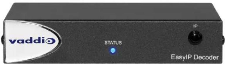
EasyIP Decoder AV-over-IP Switching USB Endpoint
Worldwide: 999-60210-000

natural_image
Product photo of a vaddi Bluetooth module with attached electronic components including USB, USB cable, and fiber optic cable (no visible text or symbols)The box should contain these items:
■ EasyIP Decoder
■ USB 3.0 cable, type A to type B, 6 ft (1.8 m)
■ Cat-5e cable, 3 ft. (0.9 m)
■ 4-position Phoenix-type connector
■ Half-rack mounting kit
■ Quick-Start Guide
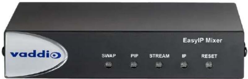
EasyIP Mixer AV Switcher
Worldwide: 999-60320-000

natural_image
Product photo of a EasyIP Mixer device with various connectors and cables (no visible text or symbols)The box should contain these items:
■ EasyIP Mixer
■ USB 3.0 cable, type A to type B, 6 ft (1.8 m)
■ Cat-5e cable, 3 ft (0.9 m)
■ 3-position Phoenix-style connectors (qty. 6)
■ Half-rack mounting kit
■ Quick-Start Guide
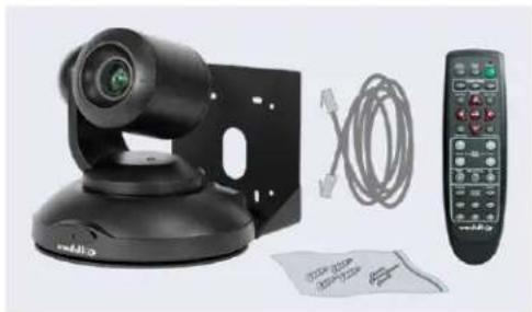
EasyIP 10 AV-over-IP PTZ Camera
Worldwide: 999-30200-000 (black), 999-30200-000W (white)
natural_image
Product photo of a black remote control unit with attached cable and paper (no visible text or symbols)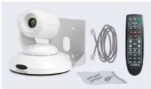
natural_image
White remote control device with camera, cable, and remote control (no visible text or symbols)The box should contain these items:
■ Camera (black or white)
■ Vaddio IR Remote Commander
■ Thin Profile Wall Mount with mounting hardware
■ Cat-5e cable, 10 ft. (3 m)
■ Quick-Start Guide
Caution
When lifting or moving a camera, always support the camera's base. Lifting the camera by its height mounting arm will damage it.

EasyIP 20 AV-over-IP PTZ Camera
Worldwide: 999-30230-000 (black), 999-30230-000W (white)

natural_image
Product photo of a black video camera with attached cable and remote control (no visible text or symbols)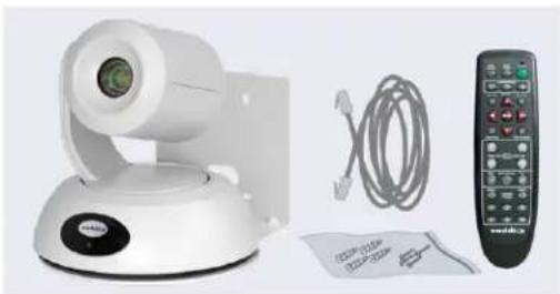
natural_image
Product photo of a white video camera with attached cable and remote control (no visible text or symbols)The box should contain these items:
■ Camera (black or white)
■ Vaddio IR Remote Commander
■ Thin Profile Wall Mount with mounting hardware
■ Cat-5e cable, 10 ft. (3 m)
■ Quick-Start Guide
Caution
When lifting or moving a camera, always support the camera's base. Lifting the camera by its height mounting arm will damage it.

A Quick Look at the EasyIP Family
- EasyIP Decoder – Decodes the AV-over-IP signal from the camera(s) and originates a USB stream.
- EasyIP Mixer – Pro A/V capabilities for the EasyIP environment.
- EasyIP 10 camera – Great video, 10x zoom, simple installation, minimal set-up.
- EasyIP 20 camera – The same great video and simple installation as the EasyIP 10, but with 20x zoom, CCU scenes, and other additional capabilities.
EasyIP Decoder
The EasyIP Decoder receives and decodes the AV-over-IP signal from the camera(s) and originates a USB stream.
Front View
Status light – Provides basic information about the device.
■ Illuminated: Normal operation.
■ Off: No power to the device.
■ Blinking: Error.
IP Address button – Press to display the decoder's IP address in its USB stream.
Dimensionally enhanced logo badge – We have spared no expense to provide a puffy logo badge to elevate your experience. It's quite shiny, and offers superior tactile appeal.
Back View

■ Network/PoE+ – RJ-45 connector. Connect to a powered port on the PoE+ switch.
- USB 3.0 – USB Type B connector. Connect to a computer for use with soft conferencing applications. Provides uncompressed USB 3.0 stream.
- EasyMic – RJ-45 connectors. Connect to a TableMIC or other microphone with EasyMic connectivity.
■ Audio output – Line level differential audio and 12 VDC power output to the optional amplified speaker or other audio infrastructure.
EasyIP Mixer
Ideal for large classrooms and multi-camera applications, the EasyIP Mixer pairs to Dante audio inputs and outputs, and manages up to four Vaddio EasyIP cameras. It's the Art of Easy in a production switcher.
Front View
- Swap button – Changes the selected input. If the PIP is turned on, this also exchanges the PIP and main image on the HDMI output.
- PIP button – Toggles the PIP on or off. Illuminated when the PIP is on.
Stream button – Toggles HDMI and USB stream on or off. Illuminated when the stream is available. - IP button – Toggles the IP address display. Illuminated when the streams are displaying the IP address instead of video.
- Reset button and power/status light – Illuminated when the device has power. Blinks to indicate an error condition. Press the button to reboot the device.
■ Dimensionally enhanced logo badge – The same lustrous bit of tactile interest that you know and love from other Vaddio equipment.
Back View
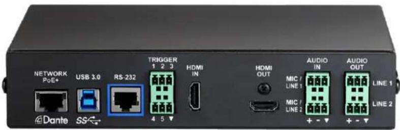
■ Network/PoE – Power, control via web interface, and Dante audio.
■ USB 3.0 – Uncompressed video output with PCM audio for conferencing applications.
■ RS-232 – Connect to an optional third-party control system.
- Trigger – Connect up to five trigger devices.
■ HDMI In – Video (and audio, if available) from a connected camera or other HDMI source.
■ HDMI Out - Output video (and audio, if available) from the selected input.
■ Audio In Mic/Line In 1 and Mic/Line In 2 – Microphone or other audio inputs. Can be configured to supply phantom power.
- Audio Out Line Out 1 and Line Out 2 – Far-end audio from conferencing application or as configured in the audio matrix.
EasyIP 10 Camera
The EasyIP 10 camera delivers great video with simple installation and minimal set-up. Use it with an EasyIP Decoder or EasyIP Mixer.
Front View

natural_image
Black Vaddi camera on a tripod stand (no visible text or symbols)Camera and zoom lens - 10X zoom lens.
IR sensor - Receives signals from the IR remote.
Status light - Multi-colored LED that indicates the camera's current state.
■ Blue - Camera is active
■ Purple – Standby mode or booting
■ Yellow – Firmware update is in progress
- Blinking red – Video mute is on (UC color scheme)
■ Blinking yellow – Motor out of calibration
Back View

natural_image
Black industrial device with circular head and support bracket, no visible text or symbolsNetwork/PoE+ - RJ-45 connector. Connect to a powered port on the PoE+ switch. It doesn't get much easier than that, does it?
EasyIP 20 Camera
The EasyIP 20 camera provides greater zoom and more sophisticated capabilities than the EasyIP 10 camera. Use it with an EasyIP Decoder or EasyIP Mixer.
Front View

natural_image
Black remote control camera with lens and base mount (no visible text or symbols)Camera and zoom lens - 20X zoom lens.
IR sensor - Receives signals from the IR remote.
Status light - Multi-colored LED that indicates the camera's current state.
■ Blue - Camera is active
■ Purple – Standby mode or booting
■ Yellow – Firmware update is in progress
- Blinking red – Video mute is on (UC color scheme)
Back View
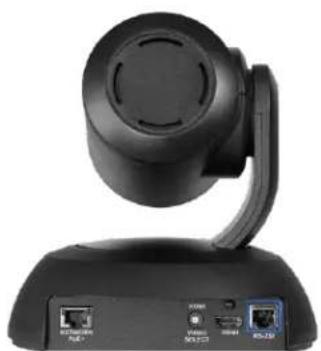
natural_image
Black remote control device with antenna and ports (no visible text or symbols)■ Network/PoE+ – RJ-45 connector. Connect to a powered port on the PoE+ switch.
- HD Video Select switch – Rotary switch to select the video output resolution. A label on the bottom of the camera lists the rotary switch settings.
■ HDMI – Local HDMI video output to an optional display.
■ RS-232 – Allows an external device to manage the camera using a modified VISCA protocol. See RS-232 Serial Communication Settings.
Installation
This section covers:
■ Tips for selecting camera locations
■ Cabling notes
■ Installing the camera mount and mounting the camera
■ System connection diagrams with cameras and audio peripherals
And a required safety note here:
Note
PoE type networks connected to this equipment are for intra-building use only and should not be to lines that run outside of the building in which this product is located.
Cameras and network-connected audio peripherals must be paired to the host device after the installation is complete.
Contact Vaddio Technical Support if you have questions or encounter any problems. Phone 800.572.2011 / +1.763.971.4400, email av.vaddio.support@legrand.com.
Don't Void Your Warranty!

Caution
When handling cameras, always support the camera's body when lifting or moving it. Lifting the head or mounting arm will damage it.
Caution
EasyIP products are for indoor use. Do not install these products outdoors or in a humid enviro without the appropriate protective enclosure.
Caution
Do not install or operate any EasyIP product if it has been dropped, damaged, or exposed to of these things happen, return the product to Vaddio for safety and functional testing.
Before You Start
Work with the network administrator to plan your EasyIP deployment. A typical EasyIP system includes network equipment.
Do these things before installing any Vaddio product:
■ Be sure you can identify all cables correctly.
■ Check Cat-5 cables for continuity.
■ Talk to the network administrator.
Inform the network administrator if you are installing the EasyIP system with a PoE+ switch. The Luxul switch sold as part of the EasyIP ecosystem is configured for DHCP operation. The network administrator may need to take steps to ensure a trouble-free installation.
- If you will be responsible for configuring the devices that you install, ask what hostnames (if any) you should assign to them.
Before Installing Cameras
Things to keep in mind when deciding where to install the camera:
- Consider camera viewing angles, lighting conditions, line-of-sight obstructions, and in-wall obstructions where the camera is to be mounted.
■ Ensure that the camera body can move freely and will normally point away from the ceiling and lights.
The camera will not perform well if it is pointed toward a light source such as a light fixture or window.
If the remote will be used, ensure that nothing blocks the IR lens in the camera's base.
Cabling Notes
The TableMIC is shipped with one Cat-5e cable to connect it to your conferencing installation.
The CeilingMIC is shipped with one Cat-5e cable to connect it to the interface box.
Caution
When building cables for Vaddio products, do not use pass-through RJ-45 connectors. Incorrectly crimped pass-through connectors can damage the connectors on the product, which will void your warranty.

Intact – will make reliable contact with cable connector

Damaged – Bent contact fingers will NOT make reliable contact with cable connector
Use Cat-5e or better cable. We recommend using high-quality connectors and a high-quality crimping tool. If connectors are crimped incorrectly, they can cause intermittent connections and degrade signal quality.

We recommend shielded cabling if the cables will be coiled, run tightly with other cables, or routed near sources of electromagnetic interference such as power lines or fluorescent light fixtures.
Caution
Check your cables. Connecting a cable to the wrong port or using the wrong pin-out can result damage and will void the warranty.
Pro Tip
Label all cables at both ends.
RS-232 Serial Communication Settings and Port Pin-outs
The EasyIP Mixer and EasyIP 20 camera have RS-232 serial ports (color-coded blue) to connect to a third-party controller.
Depending on the equipment connected to the RS-232 port, you may need a null-modem (crossover) cable.
Caution
Check your cables. Connecting a cable to the wrong port or using the wrong pin-out can result damage and will void the warranty.
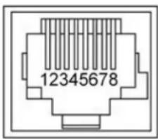
EasyIP Mixer
RS-232 connector pin-out:
■ Pin 1: Not used
■ Pin 2: Not used
■ Pin 3: Not used
■ Pin 4: Not used
■ Pin 5: Not used
■ Pin 6: GND
■ Pin 7: TXD (to RXD of connected device)
■ Pin 8: RXD (from TXD of connected device)
Communication parameters:
| Parameter Value | |
| Communication Speed 38400 | baud |
| Start bits 1 | |
| Stop bits 1 | |
| Data bits 8 | |
| Parity None | |
| Flow control None |
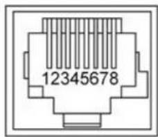
EasyIP 20 Camera
RS-232 connector pin-out:
■ Pin 1: Not used
■ Pin 2: Not used
■ Pin 3: Not used
■ Pin 4: Not used
■ Pin 5: Not used
■ Pin 6: GND
■ Pin 7: RXD (to TXD of host device)
■ Pin 8: TXD (from RXD of host device)
Communication parameters:
| Parameter Value | |
| Communication Speed 9600 or 38400 baud, selectable | |
| Start bits 1 | |
| Stop bits 1 | |
| Data bits 8 | |
| Parity None | |
| Flow control None | |
Basic Connections - EasyIP Decoder
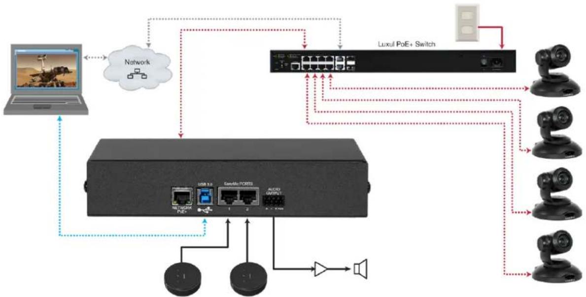
Here is an example of a simple EasyIP deployment. In this setup, an EasyIP Decoder manages up to four EasyIP cameras and provides hard-wired audio connections. A PoE+ switch provides power and network connectivity to the EasyIP products. The EasyIP Decoder connects directly to a computer as a USB conferencing device.
Vaddio recommends making all connections while the PoE+ switch is turned off.
If no PoE+ switch is used, a mid-span PoE+ power injector (sold separately) is required for each EasyIP device.
flowchart
graph TD
    A["Laptop"] --> B["Network"]
    B --> C["Network Switch"]
    C --> D["Luxul PoE+ Switch"]
    D --> E["Camera 1"]
    D --> F["Camera 2"]
    D --> G["Camera 3"]
    D --> H["Camera 4"]
    D --> I["Camera 5"]
    D --> J["Camera 6"]
    D --> K["Camera 7"]
    D --> L["Camera 8"]
    D --> M["Camera 9"]
    D --> N["Camera 10"]
    D --> O["Camera 11"]
    D --> P["Camera 12"]
    D --> Q["Camera 13"]
    D --> R["Camera 14"]
    D --> S["Camera 15"]
Caution
Do not connect the PoE+ switch to the network without guidance from an on-site network special
Note
EasyIP cameras require an EasyIP Decoder or EasyIP Mixer to decode the AV-over-IP signal and a USB stream.
The EasyIP Decoder is compatible with EasyIP cameras only. It does not detect or pair with other cameras.
Basic Connections - EasyIP Mixer
Here is an example of an EasyIP deployment using an EasyIP Mixer. In this setup, the EasyIP Mixer manages up to four EasyIP cameras and provides hard-wired audio connections for speakers. The EasyIP Mixer is paired to two network-connected EasyIP CeilingMIC D microphones. A computer connects to the system as a USB conferencing device and HDMI content source.
A PoE+ switch provides power and network connectivity to the EasyIP products. If no PoE+ switch is used, a mid-span PoE+ power injector (sold separately) is required for each EasyIP device.
Vaddio recommends making all connections while the PoE+ switch is turned off.

flowchart
graph TD
    A["User"] --> B["Network"]
    B --> C["Server"]
    C --> D["Audio Output"]
    D --> E["Output 1"]
    D --> F["Output 2"]
    D --> G["Output 3"]
    H["Network"] --> I["Computer"]
    I --> J["Video"]
    J --> K["Audio"]
    K --> L["Output 3"]
    style A fill:#f9f,stroke:#333
    style B fill:#ccf,stroke:#333
    style C fill:#cfc,stroke:#333
    style D fill:#fcc,stroke:#333
    style E fill:#ffc,stroke:#333
    style F fill:#fcc,stroke:#333
    style G fill:#ffc,stroke:#333
    style H fill:#fff,stroke:#333
    style I fill:#fff,stroke:#333
    style J fill:#fff,stroke:#333
    style K fill:#fff,stroke:#333
    style L fill:#fff,stroke:#333
Caution
Do not connect the PoE+ switch to the network without guidance from an on-site network special
Note
The EasyIP Mixer is compatible with EasyIP cameras only. It does not detect or pair with other cameras.
Basic Connections – EasyIP Mixer with HDMI Input from EasyIP 20 Camera
The EasyIP Mixer can only decode one EasyIP stream at a time. To allow the EasyIP Mixer to use an EasyIP 20 camera as the PIP source while another EasyIP camera provides the main video, connect the EasyIP 20 camera's HDMI output to the EasyIP Mixer's HDMI In port. This camera can provide the PIP when any paired EasyIP camera is selected as the main video. When the HDMI-connected camera is selected as the main video, any paired EasyIP camera can serve as the PIP source.

flowchart
graph TD
    A["Network"] --> B["Pod+E"]
    B --> C["USB 3.0"]
    C --> D["RS-232"]
    D --> E["TICKER 1 2 3"]
    E --> F["4 5 7"]
    F --> G["HOME IN"]
    G --> H["HOME OUT"]
    H --> I["MIC/LINE 1"]
    I --> J["+ - +"]
    J --> K["AUDIO OUT"]
    K --> L["MIC/LINE 2"]
    L --> M["+ - - +"]
    M --> N["Audio OUT"]
    N --> O["LINE 1"]
    N --> P["LINE 2"]
    Q["PoE+"] --> R["Video"]
    S["Network"] --> T["Computer"]
    U["Audio"] --> V["Line Video"]
    W["USB 3"] --> X["Display Screen"]
Installing the Wall Mount for the Camera
EasyIP cameras are shipped with wall mounts. Other mounting options are available as well. Contact us if you don't have the camera mount you need.
You can install the camera wall mount to a 2-gang wall box or directly to the drywall.
■ If you mount it to drywall, use the wall anchors provided with the wall mount.
■ If you mount it to a wall box, use the cover plate screws supplied with the wall box.
If you install the camera wall mount to drywall, use the wall anchors provided with the mount.
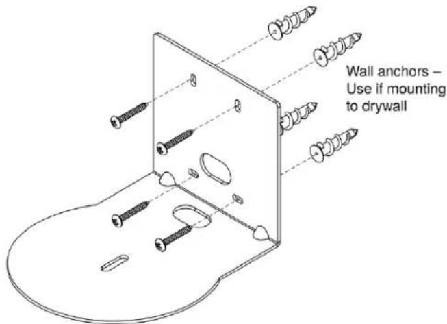
Your camera mount may look somewhat different.
Installing the Camera
- Route the cable through the opening in the mounting shelf and connect it to the camera.
- Place the camera on the mount.
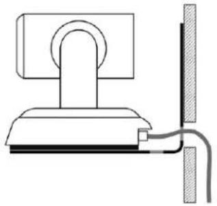
natural_image
Simple line drawing of a mechanical or electrical component with no text or symbolsImage for illustration only; not to scale. Camera and mount details may differ.
- Attach the camera to the mount using the mounting screw supplied with the camera.

Note
EasyIP 10 camera only: If the camera is jostled or bumped while it is connected to power, it m pan-tilt reset.
About Ceiling-Mounted Cameras
If you use an inverted mount, set the camera's Image Flip mode ON for inverted operation. This orients the video image correctly and sets the tilt motors to respond appropriately to tilt up and down commands from the remote, web interface, and connected control devices. This control is available to the administrator on the web interface's System page. See Inverting the Image for Ceiling-Mounted Cameras.
Powering Up the EasyIP System
Vaddio recommends making all connections while the PoE+ switch is turned off. To power the system, turn on the PoE+ switch.
■ The EasyIP Decoder's status light turns blue when the device is ready. The connected computer recognizes it as a USB peripheral.
- The EasyIP cameras initialize and move if they are powered from the same PoE+ switch. This will take a few seconds. When each camera's status light turns blue, the camera is ready to accept control information.
- The EasyIP Mixer's power light in the Reset button illuminates immediately when power is connected. The device's web interface is available after it finishes booting. This takes about 20 seconds.
Note
If a camera has already been in use and is paired with the host device, its indicator light may when it finishes booting. This happens if the camera is the selected video input and is using to color scheme. Pro A/V is the default color scheme for EasyIP 20 cameras.
Initial Set-Up and Access to Administrative Controls
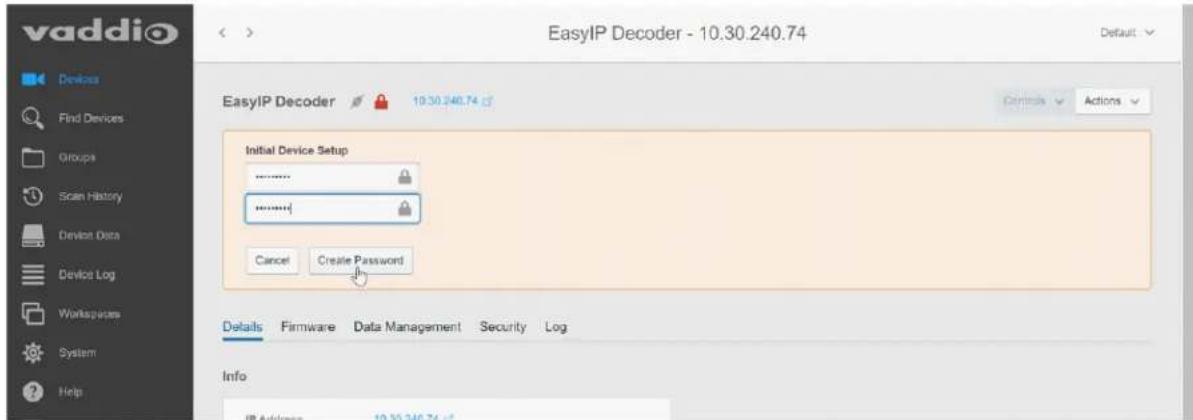
Like other Vaddio products, EasyIP cameras and host devices have a web interface for initial device setup, administrative control, and operation. After initial device setup, the web interface provides password-protected pages for administrative access to tasks such as configuring network and security settings, customizing device behaviors, and installing firmware updates. The administrator can configure the operator's pages to be password-protected or not.
When any EasyIP product is shipped from the factory, no password is set and the administrative controls are not available. Initial device set-up includes setting the password for the admin account, and may include additional tasks.

Note
Because restoring factory defaults returns the product to a "like new" condition, you will need to initial device set-up again if you restore factory defaults.
After initial device set-up is complete, you will need to complete system administration tasks to define how each device behaves as an element of your network.
Browser Support
We have tested this product with these web browsers:
Chrome®
■ Firefox®
■ Microsoft® Edge and Internet Explorer®
■ Safari®
We test using the browser version available from the vendor at that time. Other browsers (including older versions of the ones on this list) are likely to work also.
Initial Device Set-up Process Overview
- Use the Vaddio Deployment Tool – Computer application. Use it to scan the subnet to locate Vaddio devices and identify those that have not been set up, then complete the initial device set-up and go to the device's web interface. The process is the same for all products.
- Use the Vaddio Device Controller – Dedicated web interface appliance. Use it to scan the subnet and locate Vaddio devices, then exit to the device's web interface to complete the initial device set-up. The process is the same for all products.
■ Cameras only: Use the EasyIP Decoder or EasyIP Mixer to locate the camera and access its web interface. The process for locating the camera depends on the device you use to locate it. The rest of the product is the same as for other products.
- Discover the IP address and navigate to the device manually – The classic method. Discover the device's IP address and enter it in your browser's address bar to access the web interface. The way you discover the IP address depends on the device. The rest of the process is the same for all products.
The sequence of tasks for initial device set-up and system administration differs somewhat, depending on which of these methods you use.
About the Vaddio Device Controller
The Vaddio Device Controller is a stand-alone appliance for working with Vaddio products' web interfaces. Ways the Vaddio Device Controller makes your tasks easier:
- Easily scan your network for Vaddio devices – no more complicated procedures for discovering devices' IP addresses.
■ Following the scan, select a device and exit straight to its web interface.
■ No annoying messages about HTTPS connections - you automatically connect via HTTPS.
About the Vaddio Deployment Tool
The Vaddio Deployment Tool simplifies provisioning and system administration for most Vaddio products, and provides a shortcut to each device's web interface. This tool is available as a free download at https://info.legrandav.com/VaddioDeploymentTool.
Ways the Vaddio Deployment Tool makes your tasks easier:
- Easily scan your network for Vaddio devices – no more complicated procedures for discovering devices' IP addresses.
■ View scan results as a dashboard; easily identify unprovisioned and unauthenticated devices.
■ Provision new devices or update device firmware from the dashboard. - Import or export device configurations, reboot, or restore a device to factory defaults from its detail page.
■ Access devices' web interfaces directly.
■ Change a device's admin password from its detail page.
■ Standby and mute controls available on the dashboard for authenticated devices. - Organize Vaddio devices into groups – for example, by product type or physical location.
Note
The Vaddio Deployment Tool cannot detect EasyIP microphones or other products that only have connectivity. Download the free Vaddio Dante Interface Application from your microphone's page on website to manage EasyIP microphones.
Access and Initial Device Set-Up Using the Vaddio Device Controller
The Vaddio Device Controller provides a shortcut to Vaddio products' web interfaces. Unlike the Vaddio Deployment Tool, it does not need to be updated to support new products.
To complete the initial device set-up with the Vaddio Device Controller:
- Be sure the touch-panel is installed on the same subnet as the products you need to work with - for example, connect both to the same PoE+ switch.
- Go to the touch-panel's Configuration page and select Scan. You will need to enter the Vaddio Device Controller's PIN to access the Configuration page.
- Locate the device you need to work with, and select Use.
- Select Exit to leave the Configuration page and open the device's web interface.
Note
The first time you access a device at a specific IP address, the Vaddio Device Controller's s remain blank for 20 seconds or more.
- Complete the initial set-up.
Initial Device Set-Up and Access Using the Vaddio Deployment Tool
As Vaddio introduces new products, we issue updates to the Vaddio Deployment Tool. Be sure you have the latest version of the tool, to ensure that it supports the products you are working with. This tool is available as a free download at https://info.legrandav.com/VaddioDeploymentTool.
To complete the initial device set-up with the Vaddio Deployment Tool:
-
Power up the EasyIPsystem if you have not done so already.
-
On the Find Devices page of the Vaddio Deployment Tool, click Scan. If the scan does not locate the EasyIP devices, click Advanced and specify the appropriate portion of the network to scan – your computer may be on a different subnet from the EasyIPEasyIP equipment.
-
In the list of equipment that the scan discovers, locate the EasyIP devices marked Not Set Up.

-
For each device, click the Not Set Up button. The device detail page opens.
-
Set the admin password. If there are other initial set-up tasks, they are also available here.
The device now shows up as unlocked.
Pro tip
On the Groups page of the Vaddio Deployment Tool, you can create a group containing only the products.
To access EasyIP devices' web interfaces from the Vaddio Deployment Tool:
Select the device's IP address from any page where it appears. The Vaddio Deployment Tool logs you in to the web interface as admin.
Manual Access and Initial Device Set-Up
For EasyIP installations, you will need to start by completing the initial set-up for the device that manages the cameras. Then you can use the device to access the cameras' web interfaces.
For manual access and initial device set-up, the general process is:
- Discover the device's IP address and access its web interface.
- Complete the initial device set-up.
- Complete the initial system administration tasks.
Initial Access to the Web Interface
Before the product is configured, HTTP access is disabled. This is also true after restoring factory defaults. The Vaddio Deployment Tool and the Vaddio Device Controller use HTTPS.
If you browse to the web interface manually, you may encounter this message:

Switch to HTTPS if you see this message.
Expect a security warning from your browser the first time you access the device's web in Different browsers will respond with different messages and options. Your browser will probably present a message indicating one of these things:
■ The connection is not private
■ The site is not secure
■ The site is not trusted
■ The site poses a security threat
This is because the certificate (the product's website security credential) is self-signed rather than being issued by an external certificate authority. The HTTPS connection is secure and traffic is encrypted, however.
To proceed to the product's web interface, you will need to make the selections that your browser's security message discourages. The security warning page may present an option to learn more, view details, or go to the "Advanced" page. When you select the applicable option, your browser provides a button or link to continue to the IP address you entered, with a statement that it may be unsafe. Select this option. Your HTTPS connection is safe.
After you have accessed the product's web interface once, your browser remembers its IP address and will not present the security message again.
Access the Web Interface of an EasyIP Decoder or EasyIP Mixer Manually
You will need to discover the device's IP address so that you can browse to it. For this, you need a laptop with a media player application to view the USB stream from the device.
To discover the device's IP address:
- Connect the device's USB cable to your computer. Then power up the EasyIP system, if it is not already on.
-
Open a media player such as VLC Media Player and view the USB stream from the device. (If you use VLC Media Player, this is the "Open Capture Device" option under Media.) The EasyIP device is identified by its model name as an available capture device or video source.
The video output is blue or black until a camera or other video source is configured. -
Press the button marked IP or IP Address. The device's IP and MAC addresses are displayed on the video output.
If video input is available when you press this button, it is replaced by the device's information on a blue background.
- Press the button again to dismiss the information display.
To access the device's web interface:
Enter the IP address in your browser's address bar. See Initial Access to the Web Interface for information about the warning messages that you will encounter the first time you access the device's web interface.
Access the Web Interface of an EasyIP Camera Manually
After you have done the initial device set-up for the EasyIP Decoder or EasyIP Mixer, you will be able to use its web interface to locate and browse to your EasyIP cameras.
To discover a camera's IP address from an EasyIP Decoder:
- Go to the Directory page.
- If the system is already in service and cameras are paired to it, select their IP addresses to go directly to their web interfaces.
- If the device does not yet have paired cameras, follow the instructions for setting up the directory.
To discover a camera's IP address from an EasyIP Mixer:
- Go to the Video Inputs page.
- If the system is already in service and you need to discover a paired camera's IP address or access its web interface, select the appropriate EasyIP tab to display its information.
- If the camera is not already paired to the device (for example, if you are in the process of doing initial set-up and system administration for a new installation), select an EasyIP tab.
- Select Settings to open the pairing dialog.
- Select Discover Devices.

The web interface returns a list of EasyIP cameras on the EasyIP Mixer's subnet.
- Select the camera's IP address to go directly to its web interface.
Next Steps for New Deployments
After initial device set-up is complete, you will also need to complete system administration tasks to define how each device behaves as an element of your network.
Security settings – In each device's administrative web interface, you can configure product security features to conform to the IT policies for your environment. See Setting Passwords and Access.
Network settings – Depending on the requirements of your network, you may need to change the hostname. See Changing the Hostname. If additional network changes are required, work with the site's network specialist to configure the Luxul switch.
Time zone – Set the device to the appropriate time zone to ensure that timestamps in the event log are accurate. See Specifying Time Zone and NTP Server.
Room labels – Add helpful information such as the room location and phone number to the web interface of each device. See Adding Room Information to the Device's Web Interface.
The system administration pages for these tasks are virtually identical for all EasyIP products.
Dante device identification – If your installation includes the EasyIP Mixer and you are using Dante-capable audio products with it, use the Dante Controller application to locate and optionally rename the Dante devices in your installation.
Web Interface Quick Reference
Where to find the controls you need right now for camera operation, administration, and configuration. If guest access is enabled, the web interface opens to the Controls page. You must log in as admin to gain access to the administrative pages.
EasyIP Decoder Basic Operation – Operator's Pages
Access level: guest or user
■ Both pages provide access to mute, standby, video switching, and camera pan/tilt control functions.
■ On the Home page, you can also control audio volume and work with camera presets.
■ The Macros page provides access to any macros that are available.
EasyIP Mixer Basic Operation – Operator's Pages
Access level: guest or user
- All operator pages provide access to mute, standby, video switching, and camera pan/tilt control functions.
■ On the Home page, you can also work with keying, PIP, and camera presets.
■ The Audio page provides volume and mute/unmute controls for selected audio inputs and outputs. The system administrator can change these if the defaults are not suitable for your environment.
■ The Macros page provides access to any macros that are available.
System Administration (All Devices)
Access level: admin
Configure these settings on each device.
| What do you need? Go to this page | |
| Passwords and access management Security | |
| IP address, hostname, and other network settings | Networking |
| Settings related to date and time Networking | |
| Information about the device■ Room location and phone number■ Help desk phone number | Room Labels |
System Behaviors and Operation
Access level: admin
Work with these settings on the specified device.
| What do you need? Go to this page | |
| Camera settings and controls Camera (camera's web interface)Video Switching (EasyIP Decoder or EasyIP Mixer) | |
| PIP Video Switching or Video Output (EasyIP Mixer) | |
| Graphics Graphics (EasyIP Mixer) | |
| UVC-Compliant or Client Custom USB streaming | System, DIP Switches tab (EasyIP Decoder or EasyIP Mixer) |
| Speaker and microphone settings Audio (EasyIP Decoder or EasyIP Mixer) | |
| Programmable behaviors Control Devices | (EasyIP Decoder or EasyIP Mixer) |
| USB and IP streaming settings Streaming | (EasyIP Decoder or EasyIP Mixer) |
Maintenance and Troubleshooting
Access level: admin
Do these things on the affected device.
| What do you need? Go to this page | |
| ■ Update firmware or view the current firmware version■ Save (export) and restore (import) the device's configuration■ Reboot or reset to factory defaults | System: Firmware (each device) |
| Update microphone firmware | System: Peripherals (EasyIP Decoder or EasyIP Mixer) |
| Camera adjustment: Recalibrate pan and motors | System : Firmware (camera) |
| Locate Vaddio Technical Support contact information | Help (all devices) |
| View diagnostic logs | Diagnostics (each device) |
System Administration
System administration tasks define how each device behaves on your network. Although you may change device passwords regularly, other system administration tasks are usually needed only when installing the equipment.
The tasks in this chapter must be done separately on each device.
Administrative tasks are on these pages of the web interface, shown in the lower portion of the left navigation panel:
■ Networking – Network configuration, time zone and NTP server
■ Security – Passwords, guest access, other IT security-related settings
■ Room Labels – Helpful information to display in the web interface
These pages are the same for virtually all Vaddio products.
Setting Passwords and Access
SECURITY PAGE
The Account Passwords and Web Server areas of the Security page provide basic security for the web interface:
- Admin password – Required for access to the admin pages of the web interface and for Telnet access to the device.
- User password – When set, allows password-protected, non-administrative access to the operator's web interface.
- Guest access – When enabled, allows non-administrative access to the operator's web interface without a password.
- Expire idle sessions – By default, the web interface automatically logs you out after 30 minutes of inactivity.
Caution
Be sure you have a way to remember passwords after changing them. If you are not using the Deployment Tool to manage the EasyIP devices, there is no way to reset a forgotten password EasyIP 10 camera. In this situation, you may need to return the camera to the factory.

Configuring Other Security Settings
SECURITY PAGE
Depending on your environment, you may want to make these changes:
- Enable HTTP access – When selected, administrators and operators can access the product's web interface using the less-secure HTTP protocol.
■ Enable Telnet access – When selected, the device accepts Telnet connections.
Default security-related settings:
■ HTTP access is disabled
■ Telnet access is disabled
■ Device discovery is enabled
Note
Consult your network security specialist before changing any of these settings.
- Select Show Advanced Settings. The advanced options open.
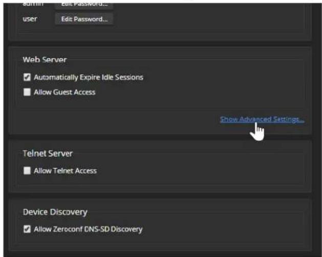
- In consultation with your network security specialist, make the desired changes.

Changing Device Hostnames
NETWORKING PAGE
Do not change network settings without guidance from an on-site network specialist.
If your network supports hostname resolution, you may find it convenient to change each device's hostname to something easy to remember. Work with your IT department to ensure that new hostnames conform to the organization's naming conventions.
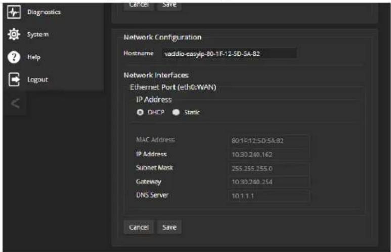
If additional network changes are required, work with the site's network specialist to configure the PoE+ switch. Refer to Luxul's manual for the switch.
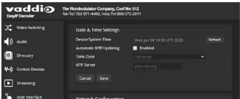
Specifying Time Zone and NTP Server
NETWORKING PAGE
Using automatic NTP updating on each device ensures that the timestamps in the device's diagnostic log are accurate. Specifying your time zone may make it easier to match logged events with other actions and external events.
- To make the time zone and NTP server editable, enable Automatic NTP Updating.
- Select the desired time zone from the list.
- If desired, specify the NTP server to use. If you are not sure about this, use the default.
You may need to refresh the system time display.
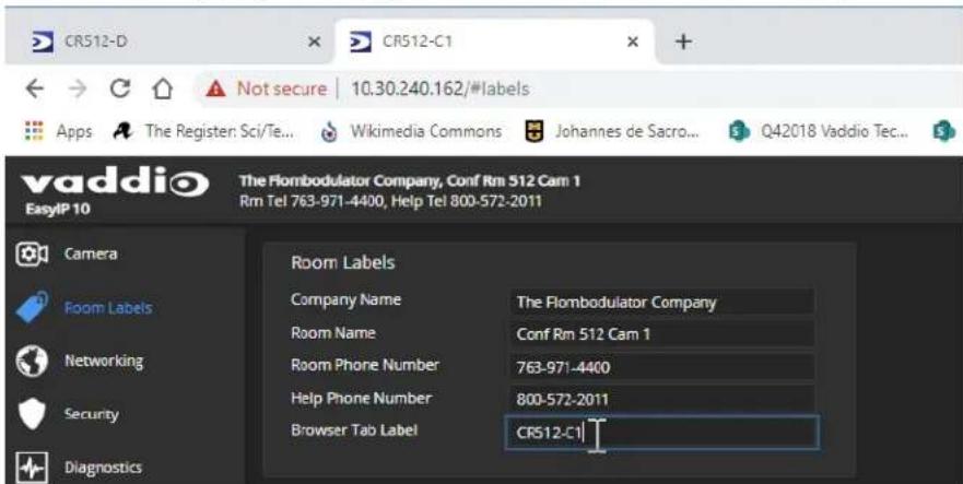
Adding Room Information to the Device's Web Interface
ROOM LABELS PAGE
The information you enter on this page is displayed on every page of the device's web interface. You may also wish to specify what appears on the device's browser tab.
Pairing EasyIP Devices
Because EasyIP products connect to each other over the IP network, they must be logically associated to each other to work together.
This chapter covers
■ Locating EasyIP devices
■ Pairing cameras to the EasyIP Decoder
■ Pairing cameras to the EasyIP Mixer
■ Routing EasyIP microphones to the EasyIP Mixer
Locating and Pairing to Cameras on the Network – EasyIP Decoder
DIRECTORY PAGE
Cameras are paired to the EasyIP Decoder if they are in its directory. Cameras may be paired to two host devices.
Status indications tell you whether each camera is currently available.
■ Disconnected – The camera is currently unavailable, or the input is not paired to a camera.
■ Unauthenticated – A camera is paired, and is waiting for you to log in as admin from this device.
■ Connected – A camera is paired, ready to send video and accept commands.

Locating and pairing to cameras works similarly on the EasyIP Mixer, but the web interface page structure is somewhat different.
To add a camera to the directory:
- Select the Edit icon (pencil) for the input to pair. The Input Pairing dialog box opens.
- To find the IP addresses of EasyIP cameras on the same subnet as the EasyIP Decoder, select Discover Devices. You can add a camera from another subnet by entering its hostname or IP address in the Host/IP Address box.

- Select one of the cameras from the list, and select Done.
Note
If a camera is paired to two or more EasyIP devices, more than one person can control the any given time. This can result in unexpected camera behavior.
- Authenticate to the selected camera. After you submit the correct admin password for the camera, the Input Pairing box shows its status as Connected.
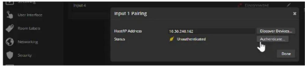
- Select Done to save the pairing and return to the main Directory view.
- If you were not able to authenticate to the camera, select its IP address from the Pairing box to open its web interface in a separate browser tab, and complete the initial device set-up. Then authenticate to the camera.
To change a directory entry:
Select the pencil (edit) icon for the desired address book entry to edit its IP address or name.
Select the X icon to delete the address book entry.
To access a camera's web interface:
Select the hostname/IP address of the desired camera. Its web interface opens in a separate browser tab.
Locating and Pairing to Cameras on the Network – EasyIP Mixer
VIDEO INPUTS PAGE
Cameras are paired to the EasyIP Mixer if the EasyIP input buttons on the Video Switching page are active. The cameras' information appears in the EasyIP Input tabs of the Video Inputs page. Cameras may be paired to two host devices.
Status indications tell you whether each camera is currently available.
- Disconnected – The camera is currently unavailable, or the input is not paired to a camera.
■ Unauthenticated – A camera is paired, and is waiting for you to log in as admin from this device.
■ Connected – A camera is paired, ready to send video and accept commands.
Locating and pairing to cameras works similarly on the EasyIP Decoder, but the web interface page structure is somewhat different.
To locate cameras on the network:
- Select an EasyIP input tab. Then select Settings to open the Pairing box.

- To find the IP addresses of EasyIP cameras on the same subnet as the EasyIP Decoder, select Discover Devices. You can add a camera from another subnet by entering its hostname or IP address in the Host/IP Address box.
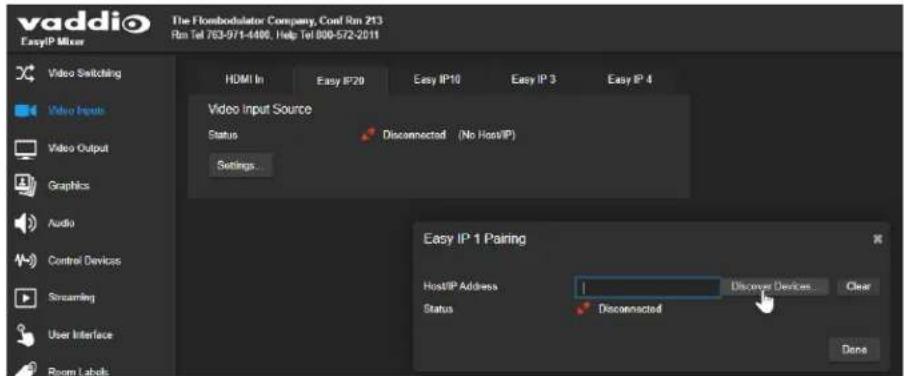
- Select one of the cameras from the list, and select Done.
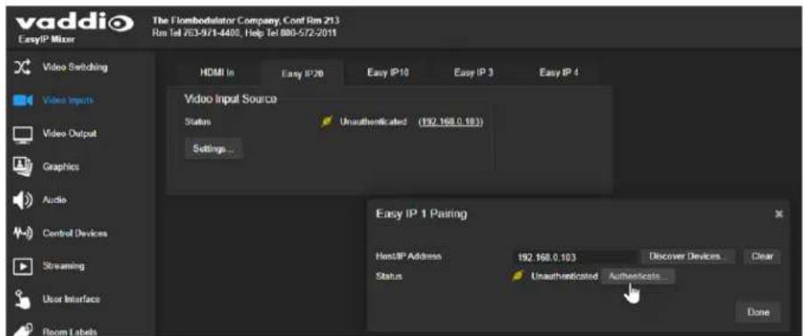
Note
If a camera is paired to two or more EasyIP devices, more than one person can control the any given time. This can result in unexpected camera behavior.
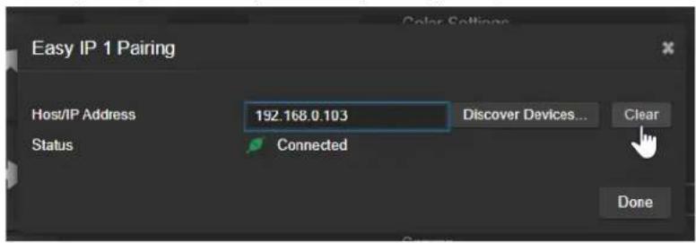
- Authenticate to the selected camera. If this is not successful, select the camera's IP address to open its web interface in a separate browser tab, and complete the initial device set-up. Then authenticate to the camera.
After you submit the correct admin password for the camera, its status shows as Connected. Select Done to save the pairing.
To access a camera's web interface:
Select the hostname/IP address of the desired camera. Its web interface opens in a separate browser tab.
Unpairing Cameras
EASYIP DECODER - DIRECTORY PAGE
If you replace or remove a camera from your EasyIP system, you can clear the pairing on the host device. The process is similar to pairing the camera.
-
Do one of these things to open the Input Pairing dialog box:
-
EasyIP Decoder: On the Directory page, select the Edit icon (pencil) for the input to unpair.
-
EasyIP Mixer: On the Video Inputs page, go to the tab for the camera to unpair, and select Settings.
-
When you open the Input Pairing dialog box, select Clear.
- Confirm that you want to clear the host/IP address.
- Select Done.

Using Dante Devices with the EasyIP Mixer
The EasyIP Mixer is compatible with Dante audio products. These products connect to the EasyIP Mixer over the network.
To pair Dante devices to the EasyIP Mixer or other Dante-compatible Vaddio products, you will need to download and install the free Dante Controller application from Audinate Pty. Ltd.:
www.audinate.com/products/software/dante-controller
Things to know about Dante technology and the Dante Controller application:
■ Dante technology does not work over Wi-Fi.
- Dante Controller does not work across subnets. Your computer must be on the same subnet as the Dante devices you need to work with.
- Default device names and IP addresses shown in Dante Controller do not match the corresponding information shown in Vaddio devices' web interfaces. The Dante Controller application uses information from the devices' Dante chips, which receive their own IP addresses.
■ Dante Controller allows you to rename devices, so you can make their identifying labels match what's displayed in the Vaddio web interface. We recommend doing this.
Audinate provides the latest information, training, and documentation for Dante technology on their website. Information in this manual about Dante technology and Audinate products may be out of date.
Locating and Pairing to Dante Devices
The Dante chip in the EasyIP Mixer has its own IP address and device name. These do not the EasyIP Mixer's hostname and IP address in the web interface.
The screen shots in this section show a different product, "AVB2x1." The process for locating the Mixer and pairing it to Dante speakers and microphones is the same.
To physically locate Dante devices using the Dante Controller application:
-
Open the Device Info tab to see the IP address and other information about each Dante device on the subnet that your computer is on.
-
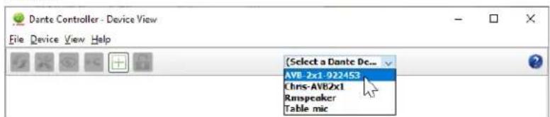
From the main Network View, select Device : Device View. The Device View window opens.
Note that EasyIP Mixer devices will show the IP address of the Dante chip, not device's web server IP address.
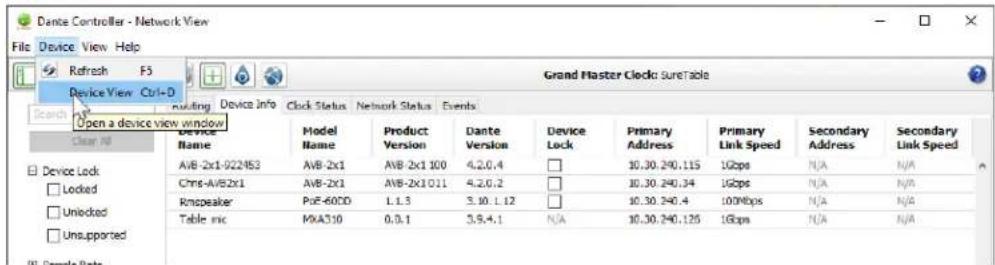
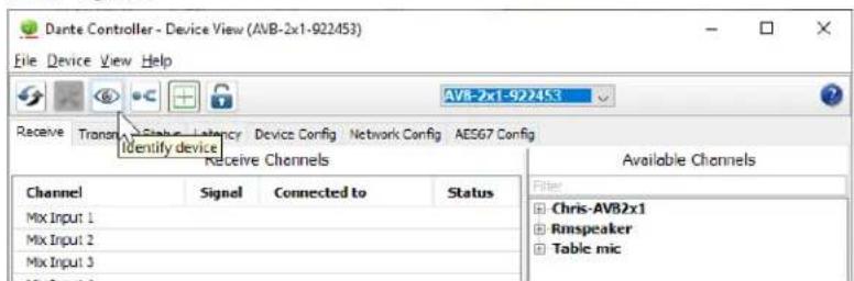
- In the Device View window, select the device of interest. The window presents information about the device.
- Select the Identify icon. The way the device responds depends on the device. The EasyIP Mixer responds by blinking all the lights on the front panel. To stop the identifying behavior, select the Identify icon again.
Other ways to access the Identify function:
The EasyIP Mixer's Audio page provides an Identify button for EasyIP microphones. The Vaddio Dante Interface Application includes an Identify button.
To pair Dante audio devices to the EasyIP Mixer:
-
From the main Network View, select Routing.
-
Use the matrix to pair receivers (speakers) and transmitters (microphones) to the EasyIP Mixer, which is both a receiver and a transmitter.
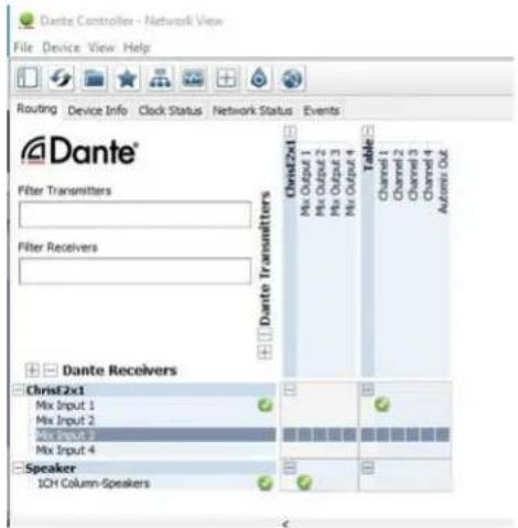
In this screen shot, the receiver "Speaker" is routed to Dante output 1 of the device "ChrisE2x1". The transmitter "Table" (a tabletop microphone) is routed to the device's Dante input 1.
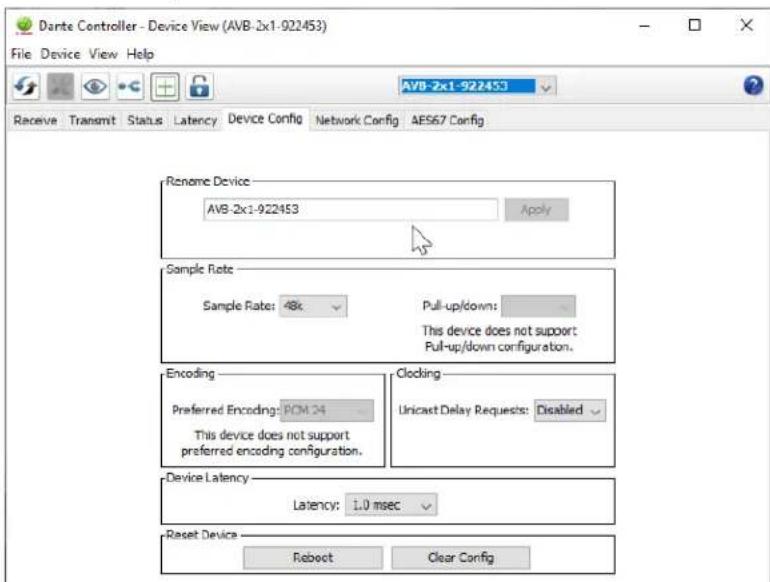
To rename a device in the Dante Controller application:
In the Device View window, select the device and go to its Device Config tab. The Rename Device option is near the top of the tab.
Pairing to More than Two EasyIP or Other Dante Microphones
In the examples that follow, we're working with a system that uses four Dante-connected microphones and a Dante-connected speaker. The system in the screen shots used an AV Bridge 2x1; the way it's configured in the Dante Controller application is exactly the same as it would be for an EasyIP Mixer.
Your devices will be labeled differently from the devices in these screen shots.
For this configuration to work properly, we will need to do these things:
- Route audio from the host device to the speaker, and route the same audio to the microphones as their AEC reference. In the example set-up, this audio channel needs to be transmitted to five devices. To allow the signal to go to five places, we will need to set up a multicast flow.
■ Create two flows to route audio from the microphones back to the host device. Although the EasyIP Mixer has four Dante input channels, it is limited to two transmit flows and two receive flows. We will need to combine the four microphone channels into two flows.
About Channels and Flows
- A channel in a Dante environment is the same thing it would be in other environments: a signal from a single source.
■ A flow in a Dante environment is one to four channels that can be routed from device to device.
Channels remain separate within the flow. For example, left and right audio channels can be part of the same flow. - By default, flows are unicast – they can only be routed to one receiving device.
- If one or more channels need to be routed to more than one device, the flow needs to be multicast. A multicast flow goes to all the receiving devices. Each device subscribes only to the channel it needs to receive.
This manual only covers the very most basic information about working with Dante products; Audinate Pty. Ltd. provides a great deal of useful information on their website. Please visit www.audinate.com/learning for documentation, tutorials, whitepapers, and more.
Creating a Multicast Flow
To allow one audio channel from the host device to go to the speaker and also serve as the AEC reference signal that goes to the four microphones in our example set-up, define a multicast flow containing only that channel.
To define the multicast flow:
- Select Device : Device View, and go to the Transmit tab.
- Select the Multicast icon (labeled 1 in this screen shot from our engineering team).
- Select the output from the host device. In this case we're using Dante Output 1, which is labeled Mix Output 1 in Dante Controller.
- Select Create.
Now Dante Output 1 is available to every device that can receive it – the speaker and the four microphones. These devices will only use the channel in the multicast flow if it is routed to them.

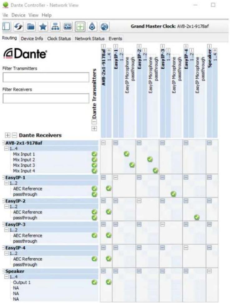
Combining Microphone Channels into Flows
The EasyIP Mixer can only receive two Dante audio flows. Each EasyIP microphone provides a pass-through channel as well as its own audio channel, so one microphone can be routed to another, which creates a flow with two microphone channels that can be routed to the host device. Think of it as daisy-chaining the microphones, but without the cable.
In the screen shot below, locate the microphones in the Dante Receivers column. Each receives its AEC reference from the Mix Output 1 channel that we set up as a multicast flow. Microphone EasyIP-1 also receives a pass-through channel from microphone EasyIP-3; microphone EasyIP-2 receives a pass-through channel from microphone EasyIP-4.
Each of the host device's four Mix Inputs receives the channel from the corresponding microphone, but the four channels are all coming from microphones EasyIP-1 and EasyIP-2.
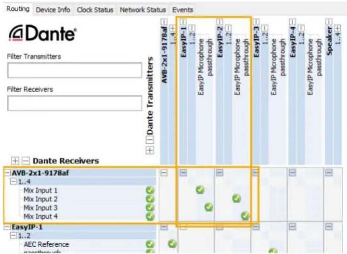
To route four microphones as two flows:
-
Decide which two microphones will be routed to the host device. In our example, it's EasyIP-1 and EasyIP-2.
-
In the Network View, look under Dante Receivers to find the passthrough row for each of these two microphones. Read across the Dante Transmitters to find the EasyIP Microphone column for the microphone originating the signal that will pass through, and select the box where they intersect.

-
Find the rows for the host device's Dante inputs. In this example, it's Mix Input 1 through Mix Input 4 of AVB-2x1-9178af. Read across the Dante transmitters to find the two microphones receiving pass-through channels.
-
For each Mix Input, select the box where the Mix Input row intersects with either the EasyIP Microphone channel or the passthrough channel, to route each microphone to the desired input.
Configuring System Behavior
This chapter covers settings on the EasyIP Decoder and EasyIP Mixer for defining how the system performs in your environment. Some configuration tasks apply to just one of the devices covered in this manual; others apply to more than one. In some cases, the steps to complete a task depend on the device.
What's in this chapter:
■ Streaming settings
■ Audio settings and adjustments
■ Video settings
■ Graphics (EasyIP Mixer)
■ Macros and triggers
■ Other system behaviors
Camera settings are covered separately in the next chapter.
Configuration Quick Reference
Configuration tasks available on the EasyIP Decoder
| What do you need to do? | Go to this page of the web interface |
| Create a list of available video sources (Camera pairing) Directory | |
| Select the active video input Video Switching | |
| Streaming settings Streaming | |
| Speaker and microphone settings Audio | |
| Set cameras to go to standby mode when the decoder goes to standby | mode User Interface |
| Programmable behaviors (macros) Control Devices |
Configuration tasks available on the EasyIP Mixer
| What do you need to do? | Go to this page of the web interface |
| Create a list of available video sources (Camera pairing) Video Inputs | |
| Select the active video input Video Switching | |
| Streaming settings Streaming | |
| Speaker and microphone settings Audio | |
| Specify the audio controls available to the non-administrative operator User Interface | |
| Set up transitions between video inputs Video Switching or | Video Output |
| Work with the PIP | Video Switching or Video Output |
| Set up keying | Graphics |
| Set cameras to go to standby mode when the decoder goes to standby | mode User Interface |
| Programmable behaviors (macros) Control Devices | |
| Disable the front panel buttons | User Interface |
Configuring Streaming Behavior
The EasyIP Decoder and EasyIP Mixer convert video from the selected input to a USB stream, which can be viewed using the computer connected to the system.
Viewing a Stream
To view the USB stream:
Connect your computer to the USB port on the EasyIP Decoder or EasyIP Mixer, and do one of these things:
■ Start or join a conference.
■ Open a stream viewer and select the EasyIP Decoder or EasyIP Mixer as the video capture device.
The device streams video from the currently selected video input.
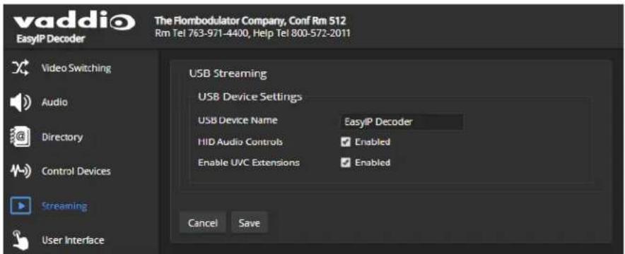
Configuring USB Streaming
STREAMING PAGE
These settings affect how the EasyIP system works with soft conferencing applications.
To change the way the EasyIP Decoder or EasyIP Mixer shows up in your soft client's ca selection list:
Edit the USB Device Name.
To allow conferencing applications to control the audio:
Check the Enabled box for HID Audio Controls.
To allow conferencing applications to control the camera:
Check the box marked Enable UVC Extensions.
Configuring the USB Stream Format for Specific Applications
SYSTEM PAGE
Depending on the conferencing application that you use, you may need to change the USB stream format. The Client Custom enables far-end camera control when used with the Zoom soft client. Use the default UVC Compliant setting with most other conferencing applications.

Configuring Audio Settings
AUDIO PAGE
The web interface provides separate controls for each of the audio inputs and outputs. The EasyIP Decoder provides simple input and output controls; the EasyIP Mixer provides the sophisticated controls of a pro A/V solution.
Some of the settings are the same for both products. Others are only available on the EasyIP Mixer.
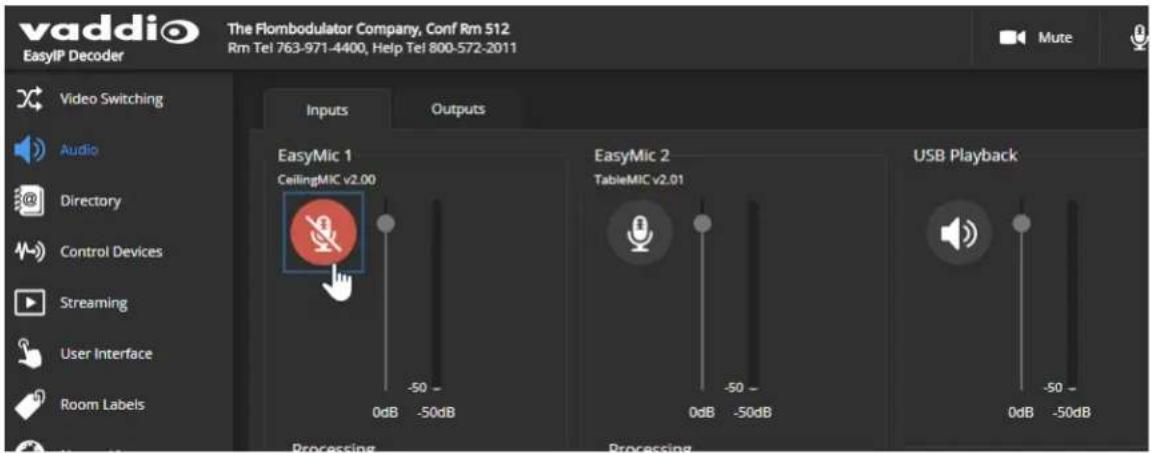
The EasyIP Decoder presents audio controls on two tabs – Inputs and Outputs.
The EasyIP Mixer groups the controls according to the signal type, and provides an audio matrix for routing inputs to outputs. Audio tabs are:
- Analog – Line/Mic inputs 1 and 2 (typically the room's microphones); audio line out 1 and 2 (typically the room's speakers).
- Dante – Up to four network-connected microphones or other audio inputs, and up to four speakers or other audio outputs. Use the Dante Controller application to pair Dante devices to the EasyIP Mixer. Use the Vaddio Dante Interface Application to access EasyIP microphone settings.
- HDMI – Left and right audio channels from the HDMI input device, and left and right audio channels to the HDMI output.
- Streaming – Left and right audio channels for USB Playback (far-end audio) and USB Record (near-end audio).
- Matrix – Defines the source (vertical axis) for each audio output (horizontal axis). Note that USB playback cannot be the source for USB record.
Muting All Audio Inputs Together
ALL PAGES
Use the audio mute button at the top of any page of the web interface. This control is present in the admin interface and the operator's interface.

Muting and Controlling Volume Per Input or Output
EASYIP DECODER - AUDIO PAGE, BOTH TABS
EASYIP MIXER – AUDIO PAGE, ALL TABS EXCEPT MATRIX
To manage individual audio inputs or outputs:
Use the slider for the appropriate audio input or output to set the volume. The audio level meter and numeric value can be helpful.
Note
For best performance with most computers, we recommend setting the USB Record volume high.
Note
Because Dante audio components connect to the network, unexpected behavior can occur. This can disruptive if the affected component is a speaker. Vaddio recommends muting Dante speakers or down their volume to the minimum setting when they are not in use.
To mute individual inputs or outputs:
Use the button to mute the desired audio input or output.
Enabling Phantom Power to Microphones – EasyIP Mixer
AUDIO PAGE, ANALOG TAB
To supply 48 VDC phantom power to a microphone connected to a Line/Mic input, check the Phantom Power checkbox below the controls for the appropriate input.

About Echo Cancellation
When a microphone picks up the audio from a speaker (far-end audio) during a conference, it sends the far-end audio back to the participants at the far end, creating an echo. Acoustic echo cancellation prevents this.
Here's how it works:
- The speaker feeds the far-end audio into the room. This signal also goes to the audio processor as the reference that needs to be canceled.
- The audio processor inverts the signal and sends it to the microphone.
- The sum of the audio that the microphone picks up from the speaker and the inverted signal is 0: The echo is canceled.

With the audio from the speaker canceled out, the audio from the microphone includes only the sounds originating at your end of the conference.
The EasyIP Mixer can use any of its audio outputs as the signal reference for acoustic echo cancellation. Select the AEC Reference at the top of the Analog or Matrix tab of the Audio page.
Fine-Tuning Microphone Performance - EasyIP Decoder
AUDIO PAGE, INPUTS TAB
To adjust microphones for best far-end audio performance:
Check or clear the checkboxes for the desired adjustments:
- Echo Cancellation – Keeps microphones from feeding the speaker output back into the system. Under most circumstances, echo cancellation is desirable.
- Noise Cancellation – Suppresses ambient noise such as the conference room's heating/air conditioning.
■ Automatic Gain Control – Adjusts gain to compensate for differences in the volume of people's voices.
■ Mic Boost – Provides a 3 dB boost.
EasyPEQ filtering offers additional options.
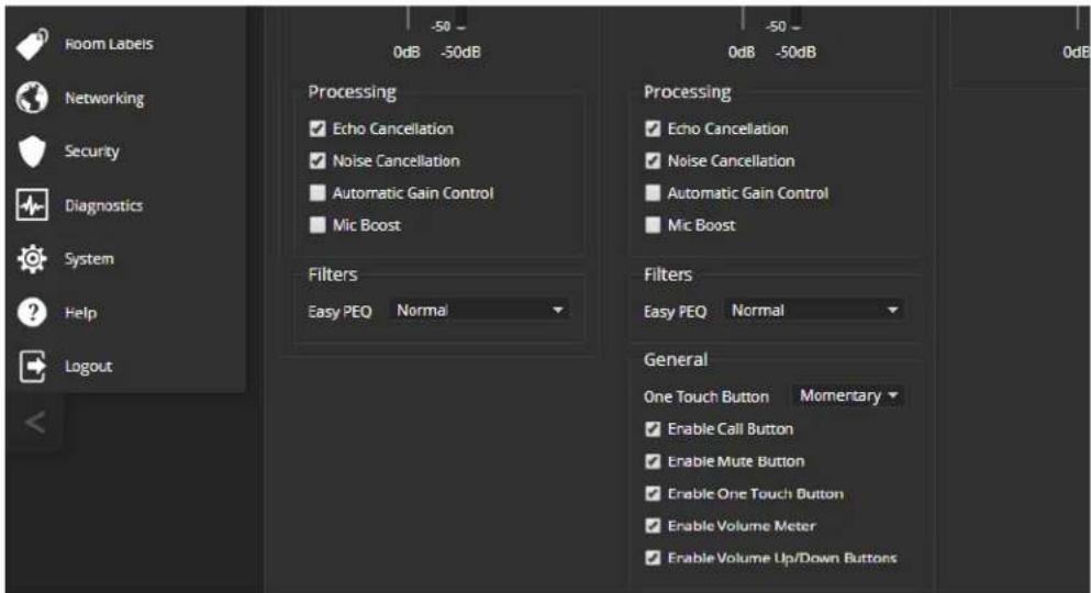
You may need to adjust the microphones to suit the room or the specific conference.
| To correct this... Do this | |
| Reverberant room From the Easy PEQ | menu, select Reverberant Room. |
| Noisy environment From the Easy PEQ | menu, select Ambient Noise to reduce gain in the frequencies above and below the normal range. |
| Participants who have quiet voices or are seated beyond the microphones' optimum pick-up range | Select the Mic Boost processing option to increase microphone gain overall.From the Easy PEQ menu, select Speech Enhancement to increase gain in the frequency range for speech. |
| Participants with widely differing vocal volumes | Select the Automatic Gain Control processing option to adjust microphone gain based on the relative volumes of people's voices. |
If two microphones are connected, they do not necessarily need to be set the same way – for example, one microphone might be set to use Mic Boost while the other is not.
Fine-Tuning Microphone Performance - EasyIP Mixer
AUDIO PAGE, ANALOG AND MATRIX TABS
EasyIP microphone settings are available through the Vaddio Dante Interface Application. See Fine-Tuning EasyIP Microphone Performance.
Presentation Adjustments
You may need to adjust the microphones for the participants.
| To accomplish this... Do this | |
| Help participants hear the person who speaking. | Enable Speech Lift and select the microphone closest to the person who is speaking. The signal from the selected microphone goes to the speakers in the room. (Analog and Matrix tabs) |
| Automatically adjust for differences in volume as different people speak | Enable Automatic Gain Control for the appropriate microphone. (Analog tab only) |
| Specify microphone priority when more one person is speaking. | Enable Chairman Override and select the microphone that has priority. (Matrix tab only) |
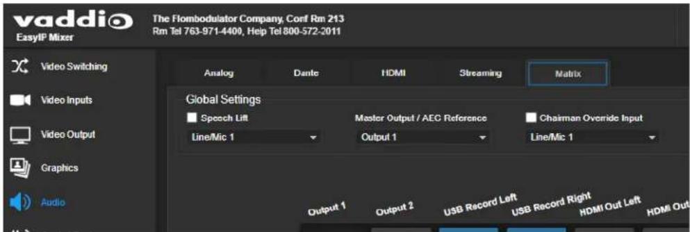
Performance Adjustments
You may need to adjust the microphones to suit the room.
| To accomplish this... Do this | |
| Specify which audio output to use as the reference for acoustic echo cancellation | Select a Master Output/AEC Reference. (Analog and Matrix tabs) |
| Reduce hissing sounds that microphones pick up. | Enable Lowpass Filter and specify the highest frequency for the microphone to pick up. (Analog tab, per microphone) |
| Reduce low-frequency background noise (such as heating/air conditioning systems) that the microphones pick up. | Enable Highpass Filter and specify the lowest frequency for the microphone to pick up. (Analog tab, per microphone) |
| Adjust the volume of specific frequency ranges to compensate for specific audio challenges. | Enable PEQ (parametric equalizer) and select Load to open the PEQ Filter window for the specified microphone. Adjust the filter settings as needed. (Analog tab, per microphone) |
Note
Use the equalizer to attenuate undesirable frequency ranges, not to boost the desirable frequencies

About the Vaddio Dante Interface Application
EasyIP and Dante technologies use differing communication protocols. Because of this, EasyIP microphone controls are not available from the web interface of the EasyIP host device, and the Vaddio Deployment Tool does not recognize them as Vaddio devices. To work with EasyIP microphones, you will need to download the free Vaddio Dante Interface Application from the microphone's product page on legrandav.com.
The Vaddio Dante Interface Application provides access to the microphone's adjustments. In the event that Vaddio releases an update to the microphone firmware, the Vaddio Dante Interface Application offers firmware update capability.
Things to know about the Vaddio Dante Interface Application:
■ The application only detects EasyIP microphones.
■ The application does not scan across subnets. Your computer must be on the same subnet as the microphones.
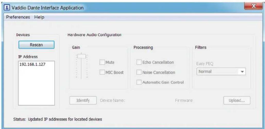
Fine-Tuning EasyIP Microphone Performance
VADDIO DANTE INTERFACE APPLICATION
The adjustments for EasyIP microphones are available via the free Vaddio Dante Interface Application. You'll find it on the Resources tab of your microphone's product page on legrandav.com.
When you open the Vaddio Dante Interface Application, it displays the IP addresses of the EasyIP microphones on the subnet. Select a microphone to enable its controls.
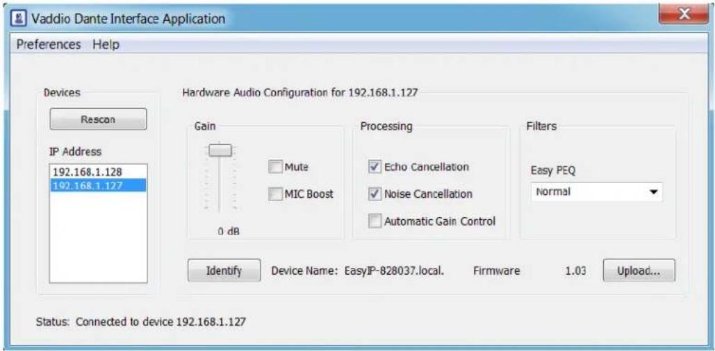
The adjustments and settings are the same as for the EasyMic family CeilingMIC and TableMIC microphones.
Presentation Adjustments
You may need to adjust the microphones for the participants.
| To accomplish this... Do this | |
| Help participants hear the person who speaking. | Select the Mic Boost processing option to increase microphone gain overall. Use the slider to set the gain From the Easy PEQ menu, select Speech Enhanceme increase gain in the frequency range for speech. |
| Automatically adjust for differences in volume as different people speak | Enable Automatic Gain Control for the appropriate microphone. |
Performance Adjustments
You may need to adjust the microphones to suit the room. Echo cancellation and noise cancellation are on by default; we recommend leaving them on.
| To correct this... Do this | |
| Reverberant room From the Easy PEQ menu, select Reverberant Room. | |
| Noisy environment From the Easy PEQ menu, select Ambient Noise to reduce gain in the frequencies above and below the normal speech range. | |
| Participants may be seated beyond microphones' optimum pick-up range | From the Easy PEQ menu, select Speech Enhancement to increase gain in the frequency range for speech.Select the Mic Boost processing option to increase microphone gain overall. |
Hardware Audio Configuration for 192.168.1.127

Status: Connected to device 192.168.1.127
Fine-Tuning Speaker Performance - EasyIP Decoder
AUDIO PAGE, OUTPUTS TAB
To reduce the dynamic range from the connected speaker:
If some people on the far end are inaudible while others are too loud, check the Compressor box.
To adjust for more natural sound:
Use the equalizer to adjust specific frequency ranges.
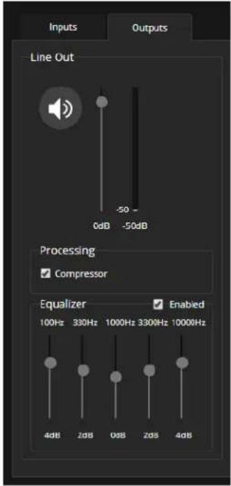
Fine-Tuning Speaker Performance - EasyIP Mixer
AUDIO PAGE, ANALOG TAB
Adjust each speaker as needed.
| To accomplish this... Do this | |
| Compensate for differing speech volumes on the far end. | Select Compressor to reduce the dynamic range from the connected speakers. |
| Compensate for specific audio issues on the far end. | Use the equalizer settings for the analog outputs to attenua specific frequency ranges. This can help if the far-end auc includes unwanted elements such as a rumbling HVAC sy or a cricket in the room. |
Note
Use the equalizer to attenuate undesirable frequency ranges, not to boost the desirable frequencies

Synchronizing Audio with Video in the USB Stream – EasyIP Mixer
AUDIO PAGE, STREAMING AND ANALOG TABS
If the video lags noticeably behind the audio in the USB stream, check the Delay box for the appropriate channel and enter a delay value in milliseconds. Right and left channels may require different delay settings.
Delay can also be set for each analog output.
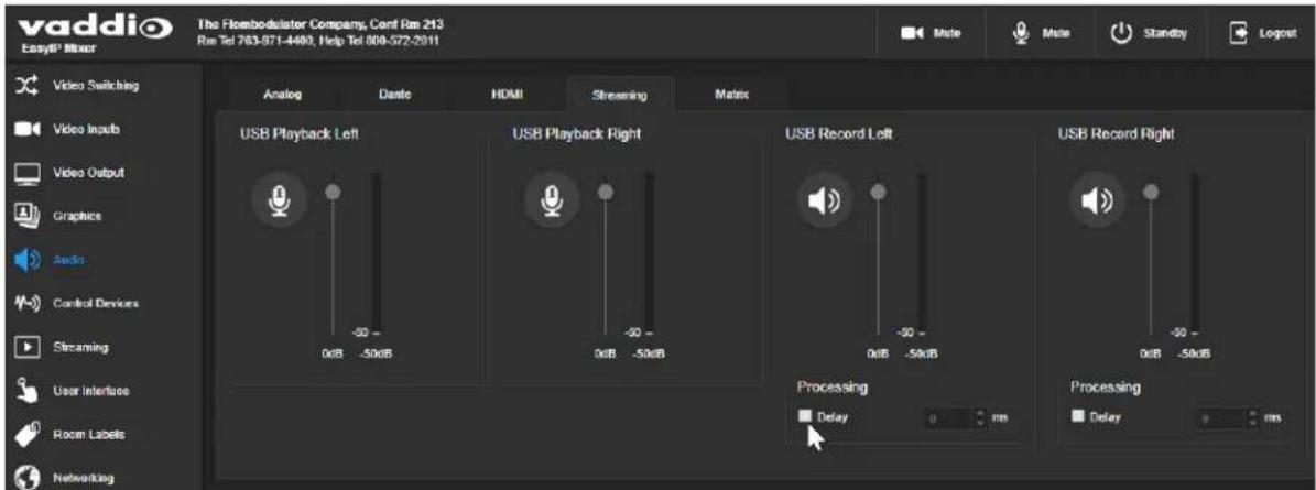
This setting is not available for the EasyIP Decoder.
Routing Audio - EasyIP Mixer
AUDIO PAGE, MATRIX TAB
The audio matrix defines where each audio output originates. Each column of the matrix shows one audio output, and each row shows one audio input. Table cells highlighted in blue mean that the input represented in that row is routed to the output represented in that column.
To specify how the EasyIP Mixer uses a given audio input:
Locate the row representing the audio input, and the column representing the desired output. Select the table cell where the desired row and column intersect.
Example: In the screen shot below,
■ The auto mic mixer feeds near-end audio into the USB stream.
■ All available audio inputs go to the auto mic mixer.
■ The left and right USB playback channels (far-end audio) feed into Output 1 (a speaker) and all the available Dante speakers. Left and right channels are separate for the HDMI output, so the HDMI audio is in stereo. Output 2 is not used.

To set the gain between input and output (crosspoint gain)
To adjust crosspoint gain between any input and the output to which it is routed, right-click the table cell in the matrix to open a gain control.

Working with Video - EasyIP Decoder
EASYIP DECODER – VIDEO SWITCHING PAGE
The EasyIP Decoder originates a USB stream with video from the input that is currently selected. When the Directory includes more than one camera or other video input, the Video Switching page lets you select which video input is active.
This page also presents the camera controls that would be available from the input camera's web interface.

Changes that you make using the camera controls on this page (such as storing and naming presets) are stored on the camera.
Working with Video - EasyIP Mixer
The EasyIP Mixer brings the video capabilities of a presentation switcher to the EasyIP family. Video controls are available on these pages:
■ Video Switching – Select the active video source, manage PIP and keying. This page is very similar to the operator's Home page in the non-administrative web interface.
■ Video Inputs – Manage HDMI input settings, pair to and control EasyIP cameras on the network.
■ Video Outputs – Manage HDMI output settings, PIP, and keying.
Working with the EasyIP Mixer's Video Inputs
VIDEO INPUTS PAGE
The web interface provides a control page with tabs for each camera and other video input device, allowing you to control the connected cameras without accessing their individual web interfaces. A red tally indicator identifies the tab for the current program source.
The tabs for EasyIP camera inputs present the same controls present in the paired cameras' own web interfaces.

Configuring the EasyIP Mixer's Video Output
VIDEO OUTPUT PAGE
The Video Output page provides controls to configure the video on the local HDMI output. Controls include:
■ Resolution/frame rate
■ Color space
■ Keying control and sources
■ PIP control and layout
PIP control and layout is also available on the Video Switching page.

Note
The PIP and the main image cannot both be EasyIP camera inputs; one or the other must be input. However, if an EasyIP 20 is connected to the EasyIP Mixer's HDMI In port, both the PIP main image will be video from EasyIP cameras. See Basic Connections – EasyIP Mixer with HDMI Input from EasyIP 20 Camera.
Working with Graphics - EasyIP Mixer
GRAPHICS PAGE
Use the graphics library to set up keying and placement for on-screen graphics.
To upload a graphics file:
- On the Library tab, Select Upload. The Upload Graphics box opens.
- Select Choose Files and browse to the file(s). File type may be .png or .jpg.
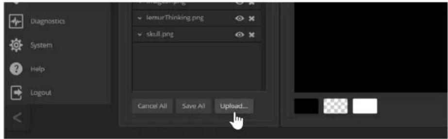
To place the graphic on the canvas and work with it:
- Select the expand/collapse arrow associated with the filename to open the file information.
- Select the View icon associated with the filename. Initially the image is placed at the top left corner of the canvas (coordinates 0,0).
- Select the desired mask type - alpha, luma, chroma, or opaque.
- Drag the image to the desired location on the canvas, or enter the desired offset from top left.
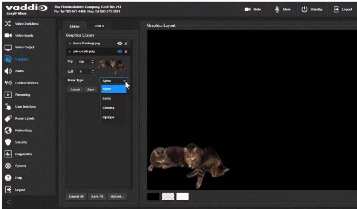
- After making changes, save your work and select the expand/collapse arrow to close the file information dialog box.
To manage the graphics library:
Right-click the filename to edit it.
Select the X to delete the file.
To work with keying layers:
- On the Bus A tab, select Source to open the Layer Source box.
- Select the desired mask type to view the graphics available.
- Select the desired graphic.
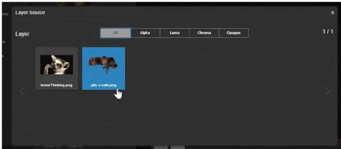
- Select the X in the upper right corner of the Layer Source box to close it. The Bus A Layout display shows the graphic in the location where it was most recently placed. You can move the graphic in the layout display on either tab of the Graphics page.

Setting up Macros and Triggers
CONTROL DEVICES PAGE
Macros are sequences of commands. Triggers register events or state changes that can be associated with macros, to make them run. For example, the One Touch (Home) button on a TableMIC is a trigger.
When you associate a macro with a trigger, you must specify whether it runs when the trigger turns on, or when it turns off – so you can associate two macros with each trigger, one to run when the trigger is activated, and one to run when the trigger is turned off.
A trigger may be either hardware, such as the Home button on a tabletop microphone, or software.
Software triggers allow you to program custom functions for third-party control devices, such as defining the buttons on a conference room touch-screen. Hardware triggers (labeled One Touch in the web interface) allow you to define responses to connected Vaddio trigger devices such as TableMIC microphones.
The macro can only run successfully if all the commands in the macro are able to run successfully. For example, if the macro sends the camera to a preset position, that preset must be defined. Refer to the Telnet Serial Command API section for a full list of commands.
The steps for working with macros and triggers are the same for the EasyIP Decoder and the EasyIP Mixer. The Control Devices pages differ in these ways:
■ The EasyIP Decoder presents One Touch triggers to associate macros with the Home button on connected TableMIC microphones.
■ The EasyIP Mixer presents hardware triggers to associate macros with devices connected to the Trigger port.
Writing and Editing Macros
CONTROL DEVICES PAGE, MACROS TAB
To define a macro:
- Enter a name in the Macro Editor's Name field.
- Enter one or more Telnet commands in the editing area. Note that camera commands must specify which camera they apply to - for example, camera 1 tilt set 10 applies to the camera paired to input 1.
- Optional but strongly recommended: Use the Test button to check your work while you are writing the macro.
- Save your work when you are finished, or select New to start over.
Note
If the macro has external requirements, it will only run properly if those requirements are met. If the macro includes a command to move to a preset, the applicable preset must be stored by macro can run successfully. I know I'm repeating myself, but this is important.
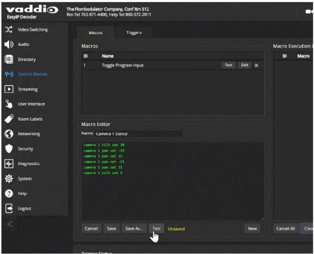
Testing Macros
CONTROL DEVICES PAGE, MACROS TAB
The Macro Editor has a Test button. You can test the macro while you are editing it, or after saving it. The Macro Execution Log shows the result of each command as the test runs.
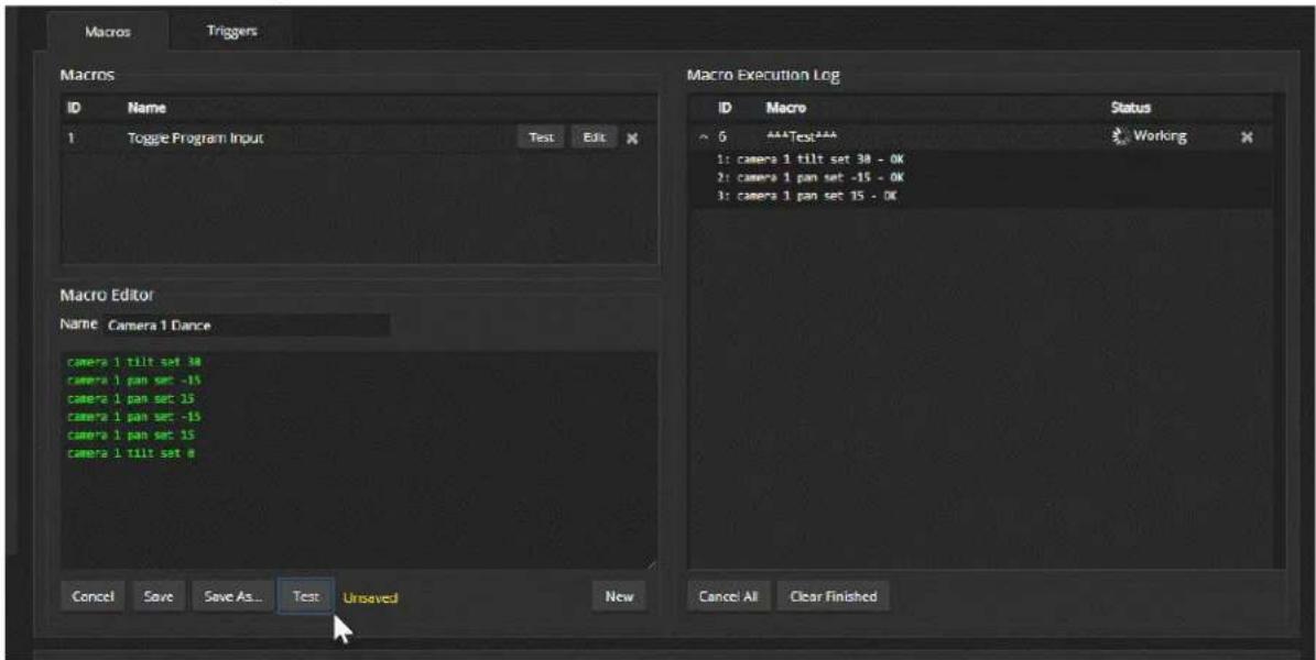
When the test finishes, the execution log shows a pass message or a fail message and hides the line-by-line results. If you need to debug the macro, you can expand the log again by selecting the down-arrow.
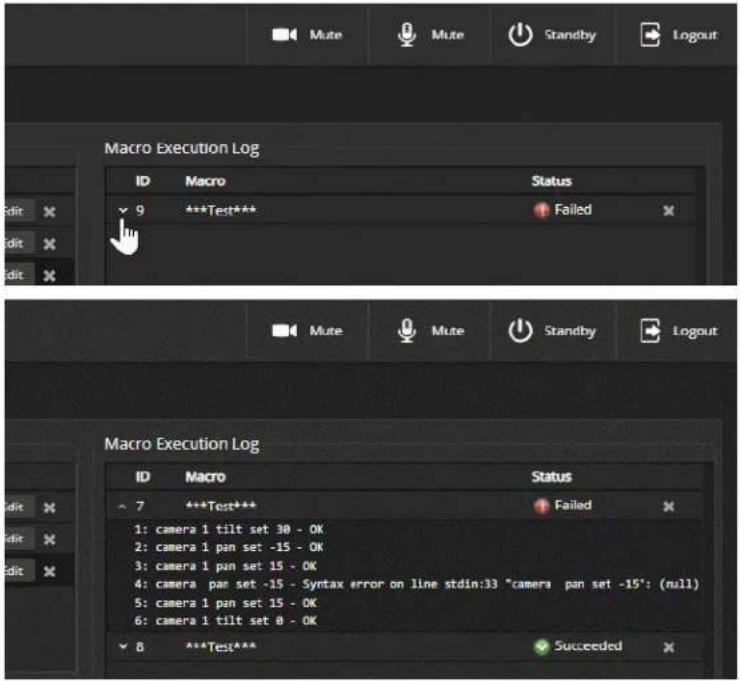
To edit an existing macro:
Select the Edit button associated with the macro, make your changes in the Macro Editor, and save your work.
To create a new macro based on an existing one:
Select the Edit button for the existing macro to open it, and use the Save As button to give it a new name. Then select its Edit button again, and make the desired changes.
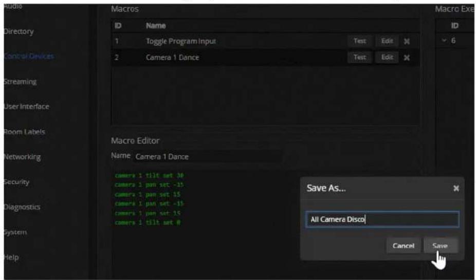
Assigning Macros to Triggers
CONTROL DEVICES PAGE, TRIGGERS TAB
A trigger may be associated with a macro that runs when the trigger is on, one that runs when the trigger is off, or one of each.
To assign a macro to a trigger:
Do at least one of these things:
■ Select a macro in the Execute Macro on Enter field. This macro will start when the trigger turns on.
■ Select a macro in the Execute Macro on Exit field. This macro will start when the trigger turns off.
Right-click a trigger label or test button to rename the trigger.
Example: Assigning a single macro to the Home button of the connected TableMIC micropho
- On the Macros tab of the Control Devices page, name and create the macro. Then test, debug, and save it.
- If you want this macro to run every time you tap the TableMIC microphone's One Touch button, got the Audio page and set the One Touch Button mode to Momentary. Otherwise it will run every other time you tap the button.
- On the Triggers tab of the Control Devices page, locate One Touch in the list of trigger events, and select the macro from the list of available actions for Execute Macro On Enter.
To remove macro assignments from a trigger:
Select the X on that trigger's row. This is equivalent to setting both macros to (none).
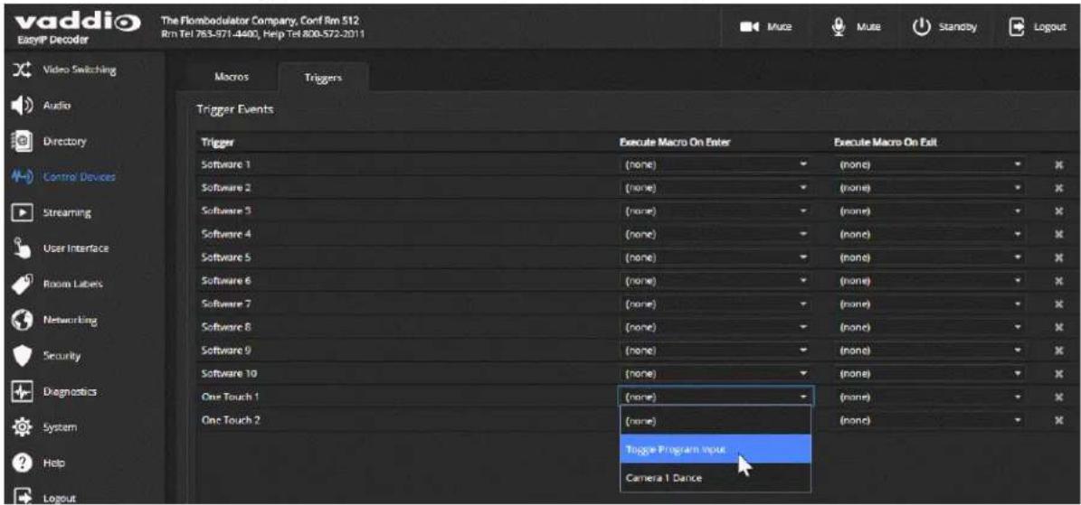
Testing Triggers
CONTROL DEVICES PAGE
Just as it can be helpful to test macros when you write them, it can also be helpful to test triggers when yo assign macros to them. The Trigger Testing section is available from both tabs of the Control Devices page.
To test a trigger:
- Set Test Mode on. The web interface displays a notification.
- Select the trigger to run the macro associated with turning the trigger on.
- Select the trigger again to run the macro associated with turning the trigger off, if there is one.
- Turn off Test Mode when you finish testing.
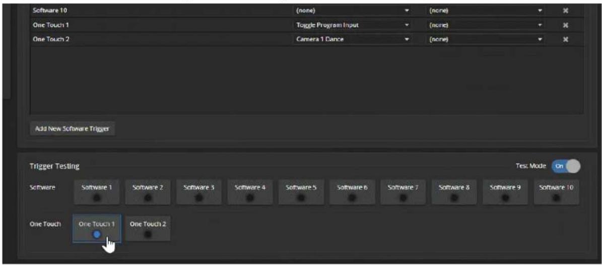
Note
Triggers are not available to the control device when Test Mode is selected.
Example: Assigning a Function to the Connected Microphone's Home Button
VIDEO SWITCHING PAGE, CONTROL DEVICES PAGE
In this example, two TableMIC microphones are connected to the EasyIP Decoder. The team that uses the conference room most frequently has requested that the Home button on the cameras' remote and the Home buttons on the two microphones should all do the same thing. The remote is normally set to control the camera that is paired to Input 1 of the EasyIP Decoder.
Tasks to accomplish this:
- Video Switching page: Select Input 1, set up the shot and color adjustments on the camera, and store the Home preset.
- Control Devices page, Macros tab: Create, name, test, and save a new macro that runs the camera 1 home command. For this example, we'll assume you name it Cam1 Home.
- Control Devices page, Triggers tab: For the OneTouch 1 trigger, click the box in the Execute on Enter column and select the Cam1 Home macro from the list. Do the same thing for the OneTouch 2 trigger.
Locking the Front Panel Controls - EasyIP Mixer
USER INTERFACE PAGE
To disable the front panel controls, check the Front Panel Lock box in the System Configuration section of the User Interface page. The front panel message shows that the controls are locked, and displays the device's IP address.
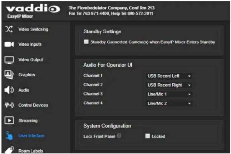
Configuring System Standby Behaviors
USER INTERFACE PAGE
EASYIP DECODER – SYSTEM PAGE, GENERAL TAB
To set standby behavior for cameras:
To control camera standby from the EasyIP Decoder or EasyIP Mixer, go to the User Interface page and select "Standby Connected Cameras when EasyIP Decoder Enters Standby."

To automatically set the EasyIP Decoder to standby when no USB connection is present: Go to the System page, select the General tab, and select "Standby Device when USB Disconnects."
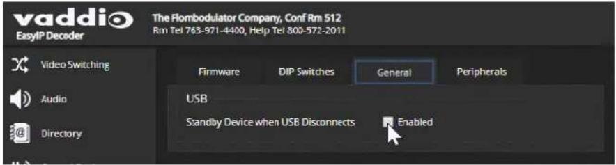
Configuring and Adjusting Cameras
Cameras are configured and adjusted individually. Image-related settings and adjustments are on the Camera page of the camera's administrative web interface. Signal-related settings and other behavior settings are also available from the System page.
Signal-related settings include:
- Camera ID – Specifies the IR frequency the camera responds to, so you can control three cameras individually using different frequency selections from the IR Remote Commander.
- IR On/Off (EasyIP 20 only) – Determines whether the camera responds to the remote.
■ Image Flip – Corrects the video orientation from inverted cameras. - Baud rate (EasyIP 20 only) – RS-232 serial communication speed; must match the device sending commands.
■ LED On/Off – Controls whether the indicator light is active.
■ HDMI color space (EasyIP 20 only) – Specifies YCbCr (default) or sRGB.
Image-related settings include:
- Home position and other preset positions – Define the position to which a camera moves when it comes out of standby mode, and any additional preset positions needed. Home and other presets include pan, tilt, and zoom information and may optionally include color adjustments. Presets 1 - 6 are available using the Vaddio IR Remote Commander; all defined presets are available from the operator's (non-administrative) web interface.
- Color and lighting adjustments – Each room may need different color and lighting settings. Cameras in different areas of the same room may also need different settings.
■ Speed adjustments – Cameras have separate speed settings for manual movements and movements to presets.
- Focus adjustment – Focus controls are also available on the IR Remote Commander, but not in the operator's web interface.
Signal-Related Settings
CAMERA PAGE, SETTINGS DIALOG
SYSTEM PAGE, DIP SWITCHES TAB
Signal-related adjustments for the EasyIP 10 camera are Camera ID and Image Flip.
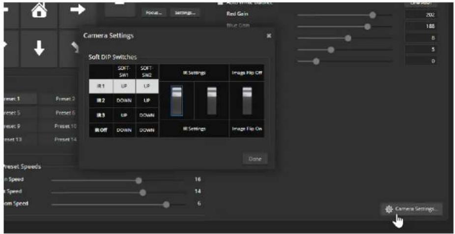

Signal-related adjustments for the EasyIP 20 camera are:
- Camera ID – Specifies the IR frequency the camera responds to, so you can control three cameras individually using different frequency selections from the IR Remote Commander.
- IR On/Off – Determines whether the camera responds to the remote.
■ Image Flip – Corrects the video orientation from inverted cameras.
■ Baud rate – Must match the baud rate of the third-party device sending commands via RS-232. - HDMI color space – Specifies YCbCr (default) or sRGB. Set to match the display connected to the camera's HDMI output.
The Codec Control Mode switch is reserved for future use.

Inverting the Image for Ceiling-Mounted Cameras
Mounting cameras on, in, or near the ceiling can create a clean-looking installation. To get a non-inverted image from an inverted camera, go to the Camera page's Settings dialog or the System page's DIP Switches tab, and set the Image Flip switch On.
Setting Cameras to Respond to Different Frequencies
If two or more cameras are in a room, you can use an IR remote to control them independently if you set them to respond to different frequencies. The Vaddio IR Remote Commander can control up to three cameras independently.
Set each camera to use IR 1, IR 2, or IR 3. These correspond to the numbered camera selection buttons or the IR Remote Commander.
Selecting the Camera to Control with the Remote
Press Camera Select button 1, 2, or 3 to select or change the IR command frequency. The camera using that frequency will recognize commands from the remote; the others will not.
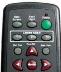
Indicator Light Behavior
SYSTEM PAGE, GENERAL TAB
Indicator light behaviors include:
■ LED on – By default the indicator is on when the camera has power.
■ LED on in standby – By default the indicator remains on while the camera is in standby (low-power mode).
■ LED color scheme – By default the EasyIP 10 camera uses the Unified Conferencing color scheme; its indicator light is blue when it is active. The EasyIP 20 camera uses the Pro AV color scheme, so its indicator light is red when it is the selected video input.
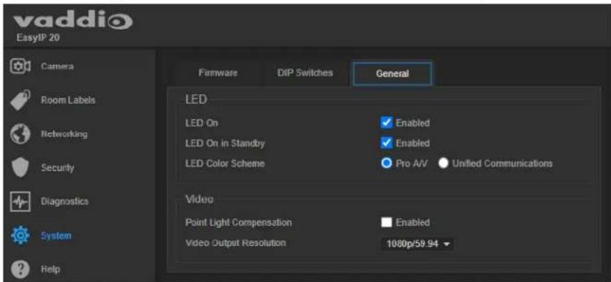
Setting the Home Position and Other Preset Shots
CAMERA PAGE
Presets are saved shots. Each preset includes pan, tilt, zoom, and (optionally) color settings. When you reboot the camera or bring it out of standby, it returns to the Home preset.
Home and presets 1 through 6 are available with the IR Remote Commander; the others are only available from the web interface.
-
Set up the shot.
-
In the Presets area, select Store to open the Store Preset dialog.
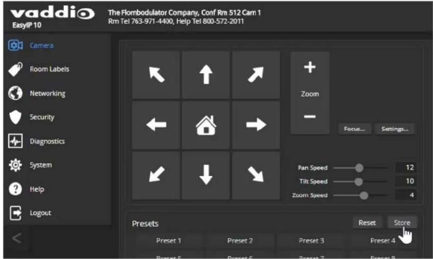
- Select the preset to store. The preset button changes color.
Note
The Store Preset dialog box does not indicate whether presets have already been defined, but display dims the preset buttons if they have no preset information stored.
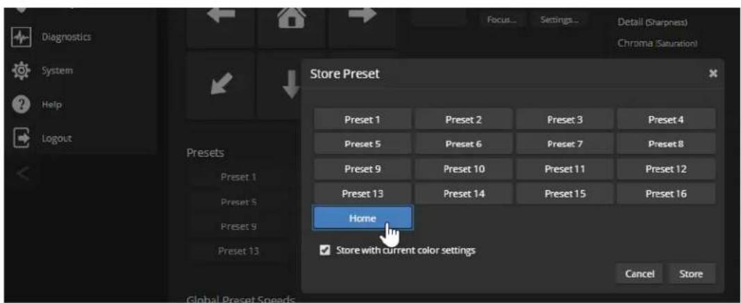
-
To save the current color settings along with the camera position, check Store with Current Color Settings.
-
EasyIP 20 cameras have the option to save Tri-Synchronous Motion speed setting with each preset. When the camera uses Tri-Synchronous Motion, the pan, tilt, and zoom movements are simultaneous and end at the same time, producing smooth, natural-looking motion.
Select Store with Tri-Sync to use this feature when moving to this preset. Use the speed slider to set the overall speed.
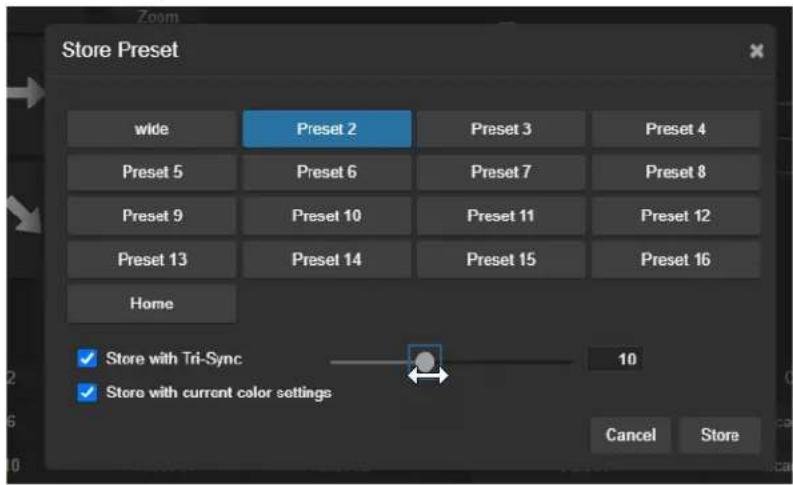
- Store the preset.
Renaming Presets
CAMERA PAGE
You can rename presets to identify them. This also helps you avoid overwriting them when you store new ones.
Right-click the button for the preset, and edit the label.

Initial Lighting and Color Settings - EasyIP 20
CAMERA PAGE
No two rooms are exactly alike – but a lot of rooms are a lot alike. The technical folks at Vaddio (Scott, to be specific) have already set up adjustments for common lighting scenarios (CCU scenes) – Incandescent Hi, Incandescent Lo, Fluorescent Hi, Fluorescent Lo, and Outdoor. The Auto setting allows the camera to determine the appropriate adjustments.
Adjust the camera for the lighting in use by selecting the CCU scene that best fits your environment.
Some adjustments to lighting and color may be necessary.
Note
Color adjustments are not available when the Auto scene is selected.

Color and Image Quality Adjustments
CAMERA PAGE
EasyIP cameras provide several color and lighting adjustments. Fine-tune the color and lighting as needed using the Color Settings controls.
■ Auto Iris allows the camera to compensate automatically for the light level. Clear this box to adjust iris and gain manually.
■ Backlight Compensation (available when Auto Iris is selected) reduces contrast to adjust for bright light behind the main subject of the shot. This setting can't be used with Wide Dynamic Range.
- Wide Dynamic Range (available when Auto Iris is selected) increases the contrast between the brightest and darkest areas. This setting can't be used with Backlight Compensation.
■ Auto White Balance adjusts color automatically. Clear this box to adjust red gain and blue gain manually.
■ Red Gain and Blue Gain (available when Auto White Balance is not selected) provide manual color adjustment.
■ Detail adjusts the image sharpness. If the video looks grainy or "noisy," try a lower Detail setting.
■ Chroma adjusts the color intensity.
■ Gamma adjusts the range (gray density) between bright areas and shadows.
The Lighting and Image Quality Quick Reference and Color Adjustment Quick Reference may be helpful.
If you make a change that you don't like, start over by selecting and then deselecting Auto Iris (lighting) or Auto White Balance (color).

The EasyIP 20 camera also offers Point Light Compensation, which reduces the intensity of small,
extremely bright areas (point light sources) that would otherwise swamp the camera with light and make it difficult to see details in areas with less intense lighting. This is on the General tab of the System page.

Saving Color and Lighting Settings – EasyIP 20
CAMERA PAGE
If you are adjusting an EasyIP 20 camera for lighting conditions that are likely to recur, you can save your adjustments as a custom CCU scene.
- Adjust lighting, image quality, and color.
- When the scene looks the way you want it to, click Store CCU Scene.
- In the Store CCU Scene dialog box, select which custom scene to store (Custom A, B, or C) and select Save.

- Optional: Name the new scene by right-clicking its button. A dialog box opens. Enter the name and save it.
Lighting and Image Quality Quick Reference
Here are some tips for using the color settings for lighting and image quality.
| What do you need to correct? Make | this adjustment: |
| The image is too dark Increase Iris (lower F-stop value) | |
| The image looks washed out or faded Decrease Iris (higher F-stop value) | |
| The subject is silhouetted against a bright background | Enable Backlight Compensation |
| Small sources of bright light (point sources) made hard to see details in areas with less intense lighting. | Enable Point Light Compensation |
| Highlights and shadows look right, but mid-toned increase Gamma are too dark. | |
| Shadows are too dark Enable Wide Dynamic Range (WDR) | |
| The image looks grainy Decrease Detail | |
| Decrease Iris Gain | |
| "Soft focus" effect; the image looks unrealistically smooth | Increase Detail |
Color Adjustment Quick Reference
Here are some tips for using the color-related CCU settings.
| What do you need to correct? Make this adjustment: | ||||
| Colors look less vivid than they should Increase Chroma | ||||
| Colors look too vivid Decrease Chroma | ||||
| Colors look wrong; white objects do not appeal white | Enable Auto White Balance | |||
| One Push White Balance | ||||
| Disable Auto White Balance and...■ adjust Red Gain (decrease for less red, inc for less green)■ adjust Blue Gain (decrease for less blue, increase for less yellow) | ||||
| Too much red Not enough red Too much blue Not enough blue Balanced | ||||
 |  |  |  |  |
If you are adjusting for lighting conditions that are likely to recur, you can store presets with color settings.
Setting the Speeds for Manual Camera Movements
CAMERA PAGE
The Pan Speed, Tilt Speed, and Zoom Speed sliders control how fast the camera moves in response to the direction and zoom controls on the IR remote and in the web interface.
To set speeds for movements using the arrow buttons:
Use the speed sliders to adjust the speed of movements that you control with the buttons for pan, tilt, and zoom. For tight shots, slower is usually better.

Setting the Speeds of Camera Movements to Presets
CAMERA PAGE
The Pan Speed, Tilt Speed, and Zoom Speed sliders in the Global Preset Speeds control how fast the camera moves to presets.
To set speeds for movements to presets:
In the Global Preset Speeds section, set the speeds for movements to presets.
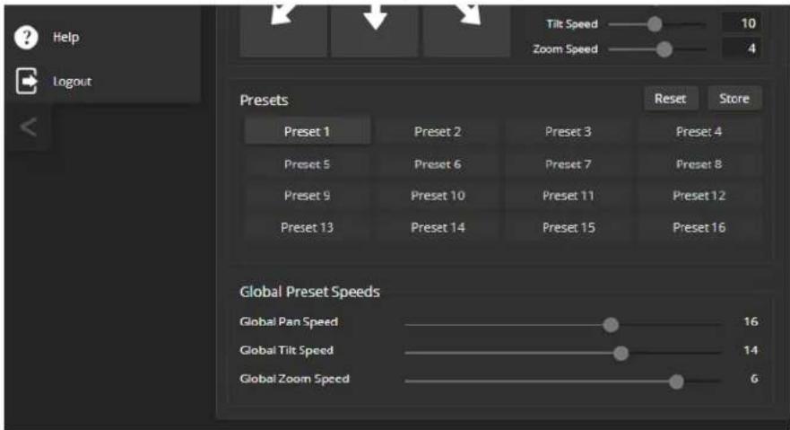
Setting the Speed for Tri-Synchronous Motion to Presets (EasyIP 20 Only)
EasyIP 20 cameras have the option to store a Tri-Synchronous Motion speed setting with each preset. When the camera uses Tri-Synchronous Motion, the pan, tilt, and zoom movements are simultaneous and end at the same time, producing smooth, natural-looking motion.
See Setting the Home Position and Other Preset Shots.
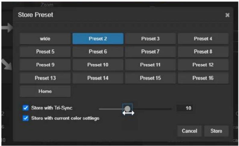
Setting the Direction for Camera Movements
CAMERA PAGE
By default, the arrow buttons on the remote and in the web interface show the direction you would see the camera move if you were looking the same direction as the camera. If a person facing the camera is controlling it with the remote, using the right arrow pans the camera to the person's left.
To make the arrow buttons indicate camera movement from the perspective of a person facing the camera, open the Settings control and invert the pan direction.
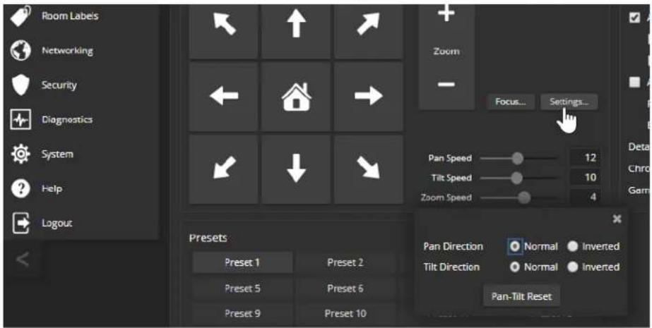
Adjusting the Focus
CAMERA PAGE
Open the Focus control to select Auto-focus, or set manual focus with the + (near) and - (far) buttons. The + and - buttons only work when Auto Focus is not selected.

For users who are not logged in as admin, focus control is available via the IR Remote Commander.
Setting HDMI Video Output Resolution - EasyIP 20 Camera
SYSTEM PAGE, GENERAL TAB
The EasyIP 20 camera provides an HDMI output for a connected display. You can set the HDMI output resolution and frame rate with the rotary switch on the back of the camera, or via the web interface. The camera ships with the rotary switch set for software control of the HDMI output resolution. The default resolution/frame rate is 1080p/59.94.
To set HDMI output resolution using the rotary switch:
Refer to the label on the camera's base, and set the rotary switch to the desired resolution.
To set HDMI output resolution via the camera's web interface:
-
Verify that the rotary switch is set to position 0, for software control. You can check this on the System page's DIP switches tab, or by selecting Camera Settings on the Camera page.
-
On the General tab of the System page, select the desired resolution and frame rate from the list.

System Maintenance
This chapter covers maintenance tasks for EasyIP cameras and host devices. Most of these are done from the affected device.
What's in this chapter:
■ Saving and restoring a device's configuration data
■ Updating firmware
■ Rebooting
Note
Some of the screen shots of these web interface pages are from the EasyIP Decoder and some the EasyIP 10 camera.
The System pages for the different products are similar to each other, but include product-specific features as well. For example, the EasyIP 10 camera's System page provides a control to recalibrate the camera's motors, and the EasyIP Decoder's System page includes a tab for updating the firmware on connected microphones.
Saving (Exporting) or Restoring (Importing) a Configuration
SYSTEM PAGE, FIRMWARE TAB
You can import a configuration to several devices of the same type if you need to configure them the same way. The devices must be of the same model and must have compatible firmware versions installed. If you need to restore a device's factory default settings, you may want to export the configuration beforehand so that you can restore customized information.
| Device Included Not Included | ||
| Camera Home | Presets | Color settingsSpeed settings |
| All devices NTP and time zone informationRoom Labels | HostnamePasswords and other security settings | |
To export a configuration:
- Configure the device with the time zone and room label. If you are working with a camera, store the presets you need.
- Export the configuration (Export Data button). The export downloads to your computer as a .dat file. The filename is the device's hostname.

- When you are ready to restore the configuration, select Import Data. The web interface prompts you to browse to the .dat file that will be imported.
To copy the configuration to a different device, do this step from the web interface of the device you need to configure.
Installing a Firmware Update
SYSTEM PAGE, FIRMWARE TAB
We release firmware updates from time to time. Some of them will be of interest to your organization; others might not be. The release notes provided with each update can help you to decide whether to install the update. The latest firmware and release notes are available on the product's web page at www.legrandav.com.
Caution
The device must remain connected to power and to the network during the update. Interrupting it could make the decoder unusable.
- Read the release notes and download the firmware.
-
Select Choose File, then browse to the downloaded firmware and select it. The filename ends with .p7m.
-
Select Begin Firmware Update.

- Read and understand the information in the Confirm dialog box.
- Select Continue. A progress message box opens. If you are updating a camera, the indicator light on the front of the camera turns yellow. If the update process presents warnings or error messages, read them carefully.
The device reboots when the update is complete, and the web interface prompts you to log in again.
Contact Vaddio Technical Support if you encounter any problems with the update.
Installing a Firmware Update for a Connected Vaddio EasyMIC Series Microphone – EasyIP Decoder
SYSTEM PAGE, PERIPHERALS TAB
The process to update microphone firmware is similar to the process for updating other devices, but is done from the EasyIP Decoder.
- Download the firmware and release notes. Microphone firmware is available on the microphone product page.
- Select Choose File and navigate to the firmware file you downloaded.
- Select the appropriate EasyMic port (1 or 2). You can only update one microphone at a time; this selection specifies which EasyMic connector the data will flow through.

4. Select Begin Firmware Update.
Note
To update EasyIP microphones, you will need to download and install the free Vaddio Dante Interface Application from legrandav.com. You'll find it on the Resources tab of your microphone's product page.
Installing a Firmware Update for an EasyIP Microphone
VADDIO DANTE INTERFACE APPLICATION
You will need the Vaddio Dante Interface Application to update EasyIP microphone firmware. This free application is available from legrandav.com on the Resources tab of your microphone's product page.
When you open the Vaddio Dante Interface Application, it displays the IP addresses of the EasyIP microphones on the subnet.
To update EasyIP microphone firmware:
- Download the firmware and release notes. Microphone firmware is available on the microphone product page.
- Open the Vaddio Dante Interface Application if you have not done so already.
- Select the microphone to update.

- Select Upload and navigate to the firmware file.
Do not disconnect the microphone while the progress bar is displayed.
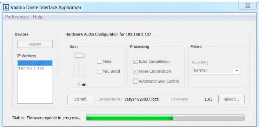
Rebooting the Device
SYSTEM PAGE
This can help if a camera or other device stops responding as you expect. In the device's System Utilities section, select Reboot.
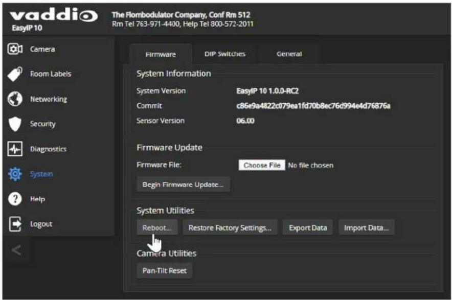
Using the Camera's Remote Control
The remote provides basic camera control.
If two cameras are in the same room, set them to respond to different IR frequencies (IR1, IR2, or IR3 settings on the System page's DIP Switches tab) and use the Camera Select buttons on the remote to specify which camera receives the commands. See Setting Cameras to Respond Independently to the IR Remote.
Quick Reference
| What do you need to do? Button(s) | |
| Power on or standby Power (green button at top right) | |
| Select the camera to control (if this ren controls more than one) | Camera Select buttons 1 through 3 (second row on the remote) |
| Discover the camera's IP address | Data Screen button (top left) – press and hold for 3 seconds |
| Move the camera Arrow buttons and Home button (dark red) | |
| Move the camera to a preset position | Position Preset buttons 1 through 6 (bottom two rows) |
| Focus the camera Auto Focus button | (near arrow buttons)Manual Focus buttons Near and Far (below Zoom Speed buttons) |
| Change zoom | Zoom buttons – T (telephoto – zoom in) and W (wide-angle –zoom out), slow and fast zoom speeds (center) |
| Adjust for excess light behind the camer subject | Black Light button (top center) |
| Correct a motor calibration fault condition (blinking yellow light) | Pan-Tilt Reset button (center right, beside arrow buttons) |
IR Remote Details
The remote provides the following functions:
Data Screen – Press and hold for 3 seconds to display the camera's IP address MAC address on the near-end display. Press momentarily to dismiss the information
Power indicator – Shows power on, IR transmission, and battery level.
Power - Switch the selected camera on or off.
Back Light - Use or turn off back light compensation.
Camera Select – In multi-camera installations, selects the camera to be contr. See Setting Cameras to Respond Independently to the IR Remote for information on configuring the camera as camera 1, 2, or 3.
Pan/Tilt (arrow button) controls and Home button - Control the camera position.
Std. Pan and Rev. Pan - Control how the camera responds to the arrow Helpful for ceiling-mounted cameras and installations where the camera will point the person using the remote.
Pan/Tilt Reset – Recalibrate the pan and tilt motors. If the camera gets jostle may need to push this button to ensure that the camera moves accurately to its and preset positions.
Auto Focus - Switch the camera to Auto-Focus mode.
Zoom Speed - Select Slow or Fast movements.
■ T (slow and fast) – Telephoto (zooms in)
■ W (slow and fast) – Wide-angle (zooms out)
Manual Focus - Switch the camera to Manual Focus mode.
Near (-) adjustment - Moves the focus nearer when in manual focus mode.
Far (+) adjustment – Moves the focus farther when in manual focus mode.
Position Presets 1 through 6 - Move the camera to a predefined position.
Preset - Save the camera's current position as one of the numbered presets.
Reset - Clear the saved position presets.
The web interface provides access to additional presets, if more than six have been set.
Storing a Preset Using the Remote
Set up the shot using the pan, tilt, and zoom controls. Then hold down the Preset button and press one of the numbered preset buttons.
Clearing a Preset Using the Remote
Press and hold the Reset button while pressing the preset number you want to clear.

Selecting the Camera to Control with the Remote
Press Camera Select button 1, 2, or 3 to select or change the IR command frequency. The camera using that frequency will recognize commands from the remote; the others will not.

Using the Operator's Web Interface
Although the cameras have their own web interfaces, operating them directly from the EasyIP Decoder or EasyIP Mixer puts the audio and video controls all in the same web interface.
Note
The operator's web interface is not available unless the user password has been set or guest a been enabled.
By default, the web interface opens to a login page, but each EasyIP device can be configured to allow non-administrative access without logging in. Check with the system administrator if you need the credentials to log in.
The EasyIP Decoder provides the basis for simple, flexible conferencing systems.
■ Most operator controls are on the Home page.
■ Video switching and access to camera pan/tilt/zoom controls are available on both the Home page and the Macros page.
■ If the administrator has defined any macros, they are available on the Macros page.

The EasyIP Mixer brings pro A/V capabilities to the conferencing environment.
■ Video switching and access to camera pan/tilt/zoom controls are available on all operator pages.
■ Camera presets are on the Home page.
■ PIP and keying controls are on the Home page.
■ Speaker and microphone controls are on the Audio page.
■ If the administrator has defined any macros, they are available on the Macros page.

Quick Steps: Muting and Standby
ALL PAGES, ANY CAMERA OR HOST DEVICE
All non-administrative pages of the web interface provide controls to do these things:
- Mute all video – HDMI Out and the USB stream send blue video. Audio remains on unless you mute it also.
- Mute all audio (not available from cameras) – Disables the microphone inputs and the audio portion of the stream. It does not disable PC audio input or HDMI audio output; if you mute audio while playing content from a PC, the audio portion of the content is not muted. Video remains on unless you mute it also.
- Set the system to standby mode – Connected cameras may also go to standby mode, depending on how the system is configured.

Note
Remember that video mute provides visual privacy but does not mute the room's microphones. Mu and audio if you need complete privacy.
Moving the Camera to a Preset Position
HOME PAGE, ANY CAMERA OR HOST DEVICE
The administrator can set up specific shots that are used often, and save them as presets on the camera. A preset specifies the camera's position and zoom level. It may also include color/lighting settings. Presets may also include motor speed information that differs from the speeds used in manually controlled movements.
Presets are only available if they have been set in the camera's administrative interface. Some devices only display presets that are available. The screen shot below is from the EasyIP Mixer, which displays all presets but dims those that have not been set.
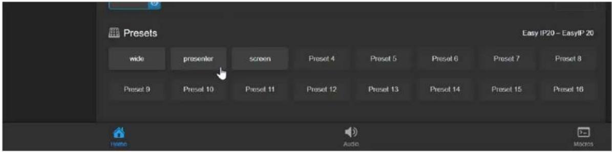
Presets 1 through 6 (if set) are also available using the IR Remote Commander.
Moving the Camera Manually
ALL PAGES, ANY CAMERA OR HOST DEVICE
The web interface provides pan, tilt, zoom, and focus controls similar to the ones on the IR Remote Commander.
To access manual camera controls:
Select Pan/Tilt Controls.
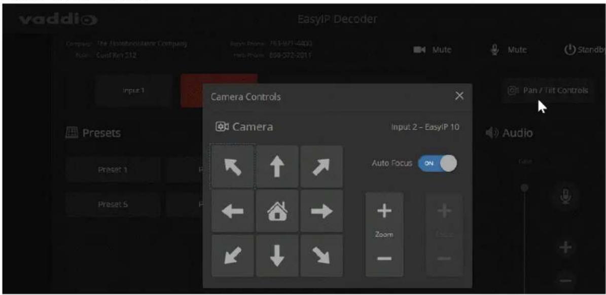
To move the camera:
Use the arrow buttons for camera pan and tilt. The center button moves the camera to the home position. Use the Zoom + button to zoom in and the Zoom - button to zoom out.
Working with Audio - EasyIP Decoder
HOME PAGE
Audio controls include mute/unmute buttons, volume read-outs, and volume slider controls for the audio output currently used as the master/AEC reference and for USB Record (the audio originating at your end of a conference).

Working with Audio - EasyIP Mixer
AUDIO PAGE
Audio controls include mute/unmute buttons, volume read-outs, and volume slider controls for the audio output currently used as the master/AEC reference and for USB Record (the audio originating at your end of a conference).
Up to four audio channels may be available on the operator's Audio page. Each provides a mute/unmute button, volume read-out, and volume slider control. The system administrator selects the audio channels available on this page.
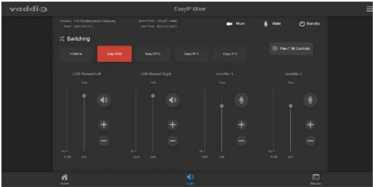
Selecting a PIP Source and Layout - EasyIP Mixer
HOME PAGE
In the web interface, the button for the active PIP source is highlighted. Either the main video or the PIP source must be the HDMI input; they can't both be EasyIP cameras.
- Select the video source to use as the PIP source. If a camera input is currently the active video, HDMI In is automatically selected as the PIP source.
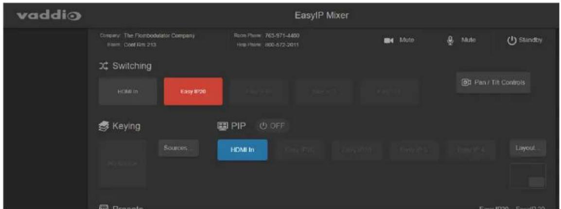
- Select Layout to open the layout selection box.
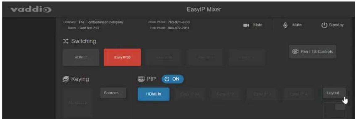
- Select the desired screen layout.
- Select Done to dismiss the layout selection box.
Working with On-Screen Graphics – EasyIP Mixer
HOME PAGE
To select a graphic:
- Select Sources. The Keying > Sources (Bus A) box displays the graphics available for the layer you select.
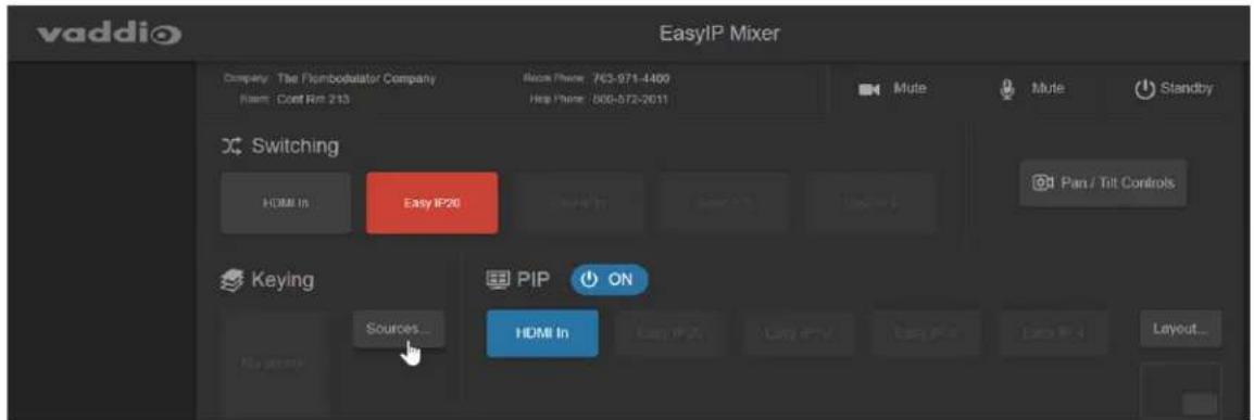
- To delete a graphic from a layer, select the X to the right of the filename.
- To add a graphic or change the graphic associated with a layer, select the desired graphic.
- Select Done to return to the main screen.

To use or hide the currently selected graphic:
Select it in the Keying area.

Serial Command API
The Vaddio serial command API allows an external device such as an AMX or Crestron presentation system to control Vaddio products. It is also used for writing macros.
■ EasyIP host devices and cameras can be controlled using this API via Telnet.
■ Host devices with RS-232 ports can also be controlled using this API via direct RS-232 connection.
■ A separate VISCA-compatible command API is available for EasyIP cameras with RS-232 ports. It is available via direct RS-232 serial connection. See RS-232 Serial Commands for EasyIP 20 Cameras.
By default, Telnet access is disabled on new Vaddio devices. Telnet access must be enabled on the device. Network connectivity and a Telnet client are also required. Telnet port 23 is used.
In addition to the device-related commands, Telnet session management commands are available – help, history, and exit.
Notes
By default, Telnet access is disabled. Enable it on the of the web interface.
When you use this API, you must log in using the ad

Usage notes:
■ The > character is the command prompt.
■ CTRL-5 clears the current serial buffer on the device.
- Using a question mark as a command or command parameter will bring up a list of available commands, subcommands, or command parameters. For example, ? returns all top-level commands; system ? returns the valid subcommands for the system command; and system reboot ? returns the parameter available for the system reboot command.
Firmware updates sometimes implement new command parameters. We do not update the manuals for every firmware update. Querying will help you discover the command parameters that have been added since the last update.
Typographical conventions:
■ n {x | y | z} - Choose x, y, or z.
■ n
■ n < x - y > - Valid range of values is from x through y.
■ n [optional] – Parameter is not required.
Camera Commands for Cameras and Host Devices
The following commands can be sent to the host device, which passes them to the camera; or they can be sent directly to a specific camera:
■ camera home
■ camera pan
■ camera tilt
■ camera zoom
■ camera focus
■ camera preset
■ camera ccu
■ camera standby
When sending any of these commands to the host device, you must specify the camera input. vary from one host device to another.
EasyIP Decoder: Cameras are specified in the command as camera 1 through camera 4.
EasyIP Mixer: Cameras are specified in the command as camera 2 through camera 5. (The HDMI input is input 1.)
camera home
Moves the camera to its home position.
When sending the command to a host device, you must specify the camera input.
| Synopsis (host device) | camerahome | |
| Synopsis (camera) | camera home | |
| Options | Specifies the camera to control. | EasyIP Decoder: 1 to 4.EasyIP Mixer: 2 to 5. |
| Example | camera 2 homeOK>(Sent to the host device) Moves the camera to its home position. For EasyIP Decoder, this is camera 2. For EasyIP Mixer it is camera 1. | |
camera pan
Moves the camera horizontally.
When sending the command to a host device, you must specify the camera input.
| Synopsis (host device) | camera <input> pan { left [] | right [] | stop | get | set[] } | |
| Synopsis (camera) | camera pan { left [] | right [] | stop | get | set[] } | |
| Options | Specifies the camera to control. | EasyIP Decoder: 1 to 4.EasyIP Mixer: 2 to 5. |
| left | Moves the camera left. | |
| right | Moves the camera right. | |
| speed <1 - 24> Optional: S | Specifies the pan speed (integer 1 to 24).Default speed is 12. | |
| stop | Stops the camera's horizontal movement. | |
| get | Returns the camera's absolute pan position in degrees, as a floating point value. | |
| set <position> Sets the camera's absolute pan position in degrees, as a floating point value. Minimum rangesEasyIP 10: -155.00 to 155.00; EasyIP 20: -150 to 150. Individual cameras may have slightly more travel before they reach their physical limits.The camera pan set command blocks execution of subsequent commands until the camera reaches the specified position. | ||
| Examples | >camera pan leftOK>(Sent to the camera) Pans the camera left at the default speed.>camera 2 pan right 20OK>(Sent to the host device) Pans the specified camera right using a speed of 20.>camera pan set -15OK>(Sent to the camera) Pans the camera to 15° left of its centerline at the default speed. | |
camera tilt
Moves the camera vertically.
When sending the command to a host device, you must specify the camera input.
| Synopsis (host device) | camera tilt { up [] | down [] | stop | get | set[] } | |
| Synopsis (camera) | camera tilt { up [] | down [] | stop | get | set[] } | |
| Options | Specifies the camera to control. | EasyIP Decoder: 1 to 4.EasyIP Mixer: 2 to 5. |
| up | Moves the camera up. | |
| down | Moves the camera down. | |
| > Optional: Integer 1 | to 20; Specifies the tilt speed.Default speed is 10. | |
| stop | Stops the camera's vertical movement. | |
| get | Returns the camera's absolute tilt position in degrees, as a floating point value. Note that the range is reversed if Image Flip is selected; negative is always down. | |
| set Sets the camera's absolute tilt position in degrees, as a floating point value. Minimum ranges EasyIP 10: -30.00 to 93.00; EasyIP 20: -30.00 to 90.00.The camera tilt set command blocks execution of subsequent commands until the camera reaches the specified position. | ||
| Examples | >camera tilt upOK>(Sent to the camera) Tilts the camera up at the default speed.>camera 1 tilt down 20OK>(Sent to the host device) Tilts the specified camera down at a speed of 20.>camera tilt set -5OK>(Sent to the camera) Tilts the camera 5° down from level at the default speed. | |
camera zoom
Moves the camera in toward the subject or out away from the subject.
When sending the command to a host device, you must specify the camera input.
| Synopsis (host device) | camerazoom { in [] | out [] | stop | get | set} | |
| Synopsis (camera) | camera zoom { in [] | out [] | stop | get | set} | |
| Options | Specifies the camera to control. | EasyIP Decoder: 1 to 4.EasyIP Mixer: 2 to 5. |
| in | Zooms the camera in. | |
| out | Zooms the camera out. | |
| Optional: Integer 1 to 7; specifies the zoom speed. | ||
| stop | Stops the camera's zoom movement. | |
| get | Returns the camera's zoom setting as a floating point value. | |
| set | Sets the camera's zoom level as a floating point value. | |
| Floating point value; specifies the zoom level.Range is 1.00 to 10.00 for EasyIP 10, 1.00 to 20.00 for EasyIP 20. | ||
| Examples | >camera zoom inOK>(Sent to the camera) Zooms the camera in at the default speed.>camera zoom stopOK>(Sent to the camera) Stops the zoom motion.>camera 2 zoom set 7OK>(Sent to the host device) Zooms the specified camera to zoom level 7. | |
camera focus
Changes the camera focus.
When sending the command to a host device, you must specify the camera input.
| Synopsis (host device) | camerafocus { near[] | far[] stop | mode {get | auto | manual} } | |
| Synopsis (camera) | camera focus { near[] | far[] stop | mode {get | auto | manual} } | |
| Options | Specifies the camera to control. | EasyIP Decoder: 1 to 4.EasyIP Mixer: 2 to 5. |
| near | Brings the focus nearer to the camera. Can only be used when camera is in manual mode. | |
| far | Moves the focus farther from the camera. Can only be used when camera is in manual mode. | |
| Optional: integer (1 to 8) specifies the focus speed. | ||
| mode [get | auto | manual] | Returns the current focus mode, or specifies automatic or manual focus. | |
| stop | Stops the camera's focus movement. | |
Examples | camera focus near 2OK>(Sent to the camera) Brings the focus near at a speed of 2.camera 2 focus mode getauto_focus: onOK>(Sent to the host device) Returns the current focus mode of the specified camera. | |
camera preset
Moves the camera to the specified preset, or stores the current camera position.
When sending the command to a host device, you must specify the camera input.
| Synopsis (host device) | camerapreset { recall | store} [1 - 16] [save-ccu] | |
| Synopsis (camera) | camera preset { recall | store} [1 - 16] [save-ccu] | |
| Options | Specifies the camera to control. | EasyIP Decoder: 1 to 4.EasyIP Mixer: 2 to 5. |
| recall <1 - 16> Moves the | camera to the specified preset. | |
| store <1 - 16> Stores the | current camera position as the specified preset. | |
| save-ccu | Optional: Saves the current CCU (color and lighting) settings as part of the preset. If not specified, the last color settings are used where recalled. | |
| Examples | >camera preset recall 3OK>(Sent to the camera) Moves the camera to preset 3.>camera 3 preset store 1OK>(Sent to the host device) Saves the specified camera's current position as | |
camera ccu get
Returns CCU (lighting and color) information.
When sending the command to a host device, you must specify the camera input.
| Synopsis (host device) | cameraccu get | |
| Synopsis (camera) | camera ccu get | |
Options | Specifies the camera to control. | |
| EasyIP Decoder: 1 to 4.EasyIP Mixer: 2 to 5. | ||
| auto_white_balance | Returns the auto white balance state (on or off). | |
| red_gain | Returns the red gain value (integer 0 to 255). | |
| blue_gain | Returns the blue gain value (integer 0 to 255). | |
| backlight_compensation | Returns the backlight compensation state (on or off). | |
| auto_iris | Returns the auto-iris state (on or off). | |
| iris | Returns the iris value (integer 0 to 11). | |
| gain | Returns the gain value (integer 0 to 11). | |
| detail | Returns the detail value (integer 0 to 15). | |
| chroma | Returns the chroma value (integer 0 to 14). | |
| gamma | Returns gamma (integer -16 to 64) | |
| wide_dynamic_range | Returns the current Wide Dynamic Range state (on or off). | |
| all | Returns all current CCU settings. | |
| Examples | >camera ccu get irisiris 6OK>(Sent to the camera) Returns the current red gain value.>camera 1 ccu get allauto_iris onauto_white_balance onbacklight_compensation offblue_gain 0chroma 5detail 8gain 1gamma -4iris 11red_gain 0wide_dynamic_range offOK>(Sent to the EasyIP Decoder) Returns current CCU settings for the Input 1 ca | |
camera ccu set
Sets the specified CCU (lighting) information.
When sending the command to a host device, you must specify the camera input.
| Synopsis (host device) | cameraccu set | |
Synopsis (camera) | camera ccu set | |
| Specifies the camera to control. | ||
| EasyIP Decoder: 1 to 4.EasyIP Mixer: 2 to 5. | ||
| auto_iris {on | off} Sets | auto-iris on or off. Auto-iris disables manual iris and gain when it is on. | |
| auto_white_balance {on off} | Sets auto white balance on or off. Auto white balance overrides red gain and blue gain manual settings. | |
| backlight_compensation {on | off} | Sets backlight compensation on or off. Can only be used when wide dynamic range is off. | |
| blue_gain <0..255> Sets bl | blue gain (integer 0 to 255). Can only be used when auto white balance is off. | |
| chroma <0..14> Sets chroma | (integer 0 to 14). | |
| detail <0..15> Sets detail | (integer 0 to 15). | |
| gain <1..11> Sets gain (integer 1 to 11). Can only be used when auto-iris is off. | ||
| gamma <-16..64> Sets gamma | (integer -16 to 64) | |
| iris <0..11> Sets iris (integer 0 to 11). Can only be used when auto-iris is off. | ||
| red_gain <0..255> Sets red | gain (integer 0 to 255). Can only be used when auto white balance is off. | |
| wide_dynamic_range {on off} | Sets Wide Dynamic Range on or off. Can only be used when backlight compensation is off. | |
| Examples | >camera ccu set auto_iris offOK>(Sent to the camera) Turns off auto-iris, returning the camera to manual iris control.>camera 2 ccu set red_gain 10OK>(Sent to the host device) Sets red gain to 10 for the specified camera. | |
camera ccu scene
EASYIP 20 CAMERA
Stores the current CCU scene or recalls the specified ccu scene.
When sending the command to a host device, you must specify the camera input.
| Synopsis (host device) | cameraccu scene {recall {factory <1-6>|custom<1-3>} | store custom <1-3>} | |
| Synopsis (camera) | camera ccu scene {recall {factory <1-6|custom<1-3>} | store custom <1-3>} | |
| Options | Specifies the camera to control. | EasyIP Decoder: 1 to 4.EasyIP Mixer: 2 to 5. |
| recall factory <1-6>recall custom <1-3> | Recalls the camera to the specified scene (factory 1 to 6 or custom 1 to 3). | |
| store custom <1-3> | Saves the current scene as the specified custom scene. | |
| Examples | >camera ccu scene recall factory 2OK>(Sent to the camera) Sets the camera to use factory CCU scene 2.>camera 2 ccu scene store custom 1OK>(Sent to the host device) Saves the current CCU scene as custom CCU scene 1. | |
camera standby
Set or change camera standby status.
When sending the command to a host device, you must specify the camera input.
| Synopsis (host device) | camera standby { get | off | on | toggle } | |
| Synopsis (camera) | camera standby { get | off | on | toggle } | |
| Options | Specifies the camera to control. | EasyIP Decoder: 1 to 4.EasyIP Mixer: 2 to 5. |
| get | Returns the camera's current standby state. | |
| off | Brings the camera out of standby (sleep) mode. | |
| on | Stops video and puts the camera in standby mode. | |
| toggle | Changes the camera's standby state - if it was not in standby mode, it enters standby; if it was in standby mode, it "wakes up." | |
| Examples | >camera standby offOK>(Sent to the camera) Brings the camera out of standby mode.>camera 3 standby getstandby: onOK>(Sent to the host device) Returns the current standby state of the specified camera. | |
Camera Commands Direct to Cameras Only
The following camera control commands must be sent directly to the camera, as they are not supported on the other EasyIP devices:
■ camera ptz-position
■ camera led
■ camera icr
camera ptz-position
CAMERA ONLY
Specifies multiple-axis movements to absolute positions.
Pan, tilt, and zoom may be specified in any order. All movements start simultaneously.
| Synopsis camera | ptz-position pan tilt zoom [no_wait] | |
| Options pan | is a floating-point value approximately - 155.00 to 155.00 for the EasyIP 10; approximately - 150 to 150 for the EasyIP 20. Individual cameras may have slightly more travel. | |
| tilt is a floating-point value approximately - 30.0 to 93.0 for EasyIP 10, -30 to 90 for EasyIP 20. Individual cameras may have slightly more travel. | ||
| zoom is a floating-point value 1.0 to 10.0 for EasyIP 10, 1.0 to 20.0 for EasyIP 20. | ||
| no_wait Optional – allows the command to return the command prompt immediately, while the requested camera movement is still in progress. | ||
| Examples | >camera ptz-position pan -15 tilt 5 zoom 1.5 no_waitOK>Moves the camera 15° left from its centerline and 5° up from horizontal, and zooms to 1.5. The command prompt appears while the camera is still in motion. | |
camera led
CAMERA ONLY
Set or change the behavior of the indicator light.
| Synopsis camera | led {get | off | on} | |
| Options | get | Returns the indicator light's current state (on or off). |
| off | Disables the indicator light. | |
| on | Enables the indicator light. | |
| Examples | >camera led offOK>Disables the indicator light. When the LED is off, you cannot tell by looking at the camera whether it is sending video.>camera led getled: onOK>Returns the current state of the indicator light. | |
camera icr
CAMERA ONLY
Gets or sets the state of the camera's IR cut filter.
| Synopsis camera | icr {get | on | off} | |
| Options | get | Returns the IR cut filter mode. |
| on | Sets the IR cut filter on. | |
| off | Sets the IR cut filter off. | |
| Examples | camera icr getIR(Cut) filter off(In)>Returns the current IR cut filter state (off, in this case).camera icr onOK>Sets the IR cut filter on. | |
Video Management Commands
The following commands are valid for the EasyIP Decoder, EasyIP Mixer, or both. The video mute command is also available on EasyIP cameras.
■ video mute
■ video pip
■ video source
■ video type (EasyIP Decoder only)
video mute
Gets or sets the video mute status. When video is muted, the USB stream displays as a blue screen. This can be desirable when preparing the room, or when privacy is needed.
| Synopsis video mute {get | off | on | toggle} | ||
| Options | get | Returns the current video mute status. |
| off | Unmutes the video. (Normal video resumes.) | |
| on | Mutes the video. (Blue screen) | |
| toggle | Changes the video mute status. | |
| Examples | >video mute getmute: offOK>Returns video mute status.>video mute onOK>Transmits blue or black video. | |
video pip
EASYIP MIXER
Get or set the state of the PIP.
In a call, the PIP is near-end video (the selected input); the main image is far-end video.
| Synopsis video pip {get | on | off | toggle | layout} | ||
| Options | get | Returns the current state of the PIP. |
| on | Enables the PIP. | |
| off | Disables the PIP. | |
| toggle | Changes the state of the PIP. | |
| layout | Specifies the screen lay-out. The PIP may be in any corner of the screen, or the screen may be split vertically or horizontally. | |
| layout get | Returns the screen layout that is used when the PIP is on. | |
| Examples | video pip layout left_rightOK>Sets the video output to show side-by-side images of the video output and PIP. | |
video source
EASYIP DECODER, EASYIP MIXER
Gets or sets the device's video source.
Camera inputs for the EasyIP Decoder are inputs 1 through 4. Camera inputs for the EasyIP M inputs 2 to 5, corresponding to camera inputs 1 through 4. Input 1 is reserved for HDMI in.
| Synopsis video source { get | set } | ||
| Options | get | Returns the video input that is currently select |
| set | Sets the video input that is currently selected. | |
| Input. | ||
| Examples | >video source getsource: input2OK>Returns the video input that is currently selected, Input 2.>video source set input1OK>Sets Input 1 as the selected video source. | |
video type
EASYIP DECODER
Gets or sets the type of video associated with the specified input device.
| Synopsis videotype {get | set {camera | video}} | ||
| Options | Specifies the input device (1 to 4). | |
| get | Returns the input device's video type. | |
| set | Sets the input device's video type. | |
| camera | Specifies the input device as a camera. | |
| video | Specifies the input device as a video input other than a camera. | |
| Examples | >video input1 getinput type: cameraOK>Returns the type of device at input 1. | |
Audio Management Commands
The following commands are valid for the EasyIP Decoder and EasyIP Mixer:
■ audio mute
■ audio volume
The following commands are valid for the EasyIP Mixer only:
■ audio route
■ audio crosspoint-gain
Audio Channels Available on the EasyIP Decoder
The following channels can be specified when sending audio commands to the EasyIP Decoder.
| master | Applies the command to all audio channels. |
| Inputs | |
| easy_mic_1easy_mic_2 | Applies the command to the external microphone connected to the specified EasyMic port. |
| usb_playback | Applies the command to the audio portion of the incoming (far-end) USB stream |
| Outputs | |
| master | Applies the command to all audio channels. |
| line_out_1 | Applies the command to the audio from the connected speaker. |
| usb_record | Applies the command to the outbound (near-end) audio portion of the USB stream |
Audio Channels Available on the EasyIP Mixer
The following channels can be specified when sending audio commands to the EasyIP Mixer.
| master | Applies the command to all audio channels. |
| Inputs | |
| line_in_1line_in_2 | Applies the command to the external microphone or line-level input connected to the specified audio line in port. |
| usb3_playback_leftusb3_playback_right | Applies the command to the specified USB playback channel (audio from the far end). |
| hdmi_in_lefthdmi_in_right | Applies the command to the specified HDMI audio channel from HDMI input 1. |
| dante_in_1dante_in_2dante_in_3dante_in_4 | Applies the command to the specified Dante-connected microphone. (audio mute and audio volume only) |
| Outputs | |
| line_out_1line_out_2 | Applies the command to the speaker or line-level output device connected to the specified audio line out port. |
| usb3_record_leftusb3_record_right | Applies the command to the specified USB record channel (audio from the near end). |
| hdmi_out_lefthdmi_out_right | Applies the command to the specified HDMI audio channel for the HDMI output. |
| dante_out_1dante_out_2dante_out_3dante_out_4 | Applies the command to the specified Dante-connected speaker or other output device. (audio mute and audio volume only) |
audio mute
EASYIP DECODER, EASYIP MIXER
Gets or sets the mute status of the specified audio channel.
| Synopsis audio < | channel > mute {get | on | off | toggle} | |
| Channels | Refer toAudio Channels Available on the EasyIP DecoderorAudio ChannelsAvailable on the EasyIP Mixer, as appropriate. | |
| Options | get | Returns the current mute status of the specified channel. |
| on | Mutes the audio for the specified channel. | |
| off | Unmutes the audio for the specified channel. | |
| toggle | Changes the mute state for the specified channel – unmutes if it was muted, mutes if it was not. | |
| Examples | >audio line_out_1 mute getmute: offOK>Returns the current mute state of the device connected to audio line out 1. Mute is off, so the audio is on.>audio master mute onOK>Mutes all audio. | |
audio volume
EASYIP DECODER, EASYIP MIXER
Gets or sets the volume of the specified audio channel.
| Synopsis audio < | channel > volume {get | up | down | set} | |
| Channels | Refer toAudio Channels Available on the EasyIP DecoderorAudio Channels Available on the EasyIP Mixer, as appropriate. | |
| Options | get | Returns the current volume of the specified channel. |
| up | Increases the volume of the specified channel. | |
| down | Reduces the volume of the specified channel. | |
| set | Sets the volume of the specified channel. | |
| Examples | audio line_in_1 volume set -5OK>Sets -5 dB as the volume for the device connected to the Line In 1 port.audio line_out_1 volume getvolume -10.0 dBOK>Returns the current volume for the speaker connected to the line out port. | |
audio route
EASYIP MIXER
Gets or sets the input routed to the specified output.
| Synopsis audioroute {get | set} | ||
| Channels Refer to | Audio Channels Available on the EasyIP Mixer. | |
| Options | get | Returns the routing for the specified output. |
| set | Sets the routing for the specified output. | |
| Examples | >audio usb3_record_left route get[auto_mic_mix]OK>Returns the current source of the left channel of USB3 Record. The auto m currently routed to the left channel of the USB3 Record output. | |
audio crosspoint-gain
EASYIP MIXER
Returns or sets the input routing gain, in dB, for a given output and input.
| Synopsis audio <output> crosspoint-gain <input> {get | set <level>} | ||
| Channels Refer to Audio Channels Available on the EasyIP Mixer. | ||
| Options | get | Returns the routing gain from the specified input to the specified output. |
| set <-12.00 .. 12.00> | Sets the routing gain from the specified input to the specified output. Valid range is -12.00 dB to 12.00 dB. | |
| Examples | >audio line_out_1 crosspoint-gain hdmi_in_left get3.95OK>Returns the current gain setting of the crosspoint between Line Output 1 and HDMI Input Left in dB.>audio usb3_record_left crosspoint-gain line_in_1 set 6.00OK>Sets the crosspoint gain of USB Record Left and Line In 1 to 6 dB. | |
Communication and Network Commands
The EasyIP Decoder and EasyIP Mixer support commands to establish communication with cameras and to discover current streaming settings. Most Vaddio devices support the network settings get command.
■ camera authenticate
■ camera comm host
■ streaming settings get
■ network settings get (can also be sent directly to the camera)
camera authenticate
EASYIP DECODER, EASYIP MIXER
Authenticate to a camera in the directory.
| Synopsis camera | authenticate | |
| Options | Specifies the camera to control. | EasyIP Decoder: 1 to 4.EasyIP Mixer: 2 to 5. |
| The camera's admin password. | ||
| Examples | >camera 1 authenticate**********OK> | |
camera comm host
EASYIP DECODER, EASYIP MIXER
Pairing operations – get the IP address of the device at the specified input, add or delete a device.
| Synopsis camera | ||
| Options | Specifies the camera to control. | EasyIP Decoder: 1 to 4.EasyIP Mixer: 2 to 5. |
| get | Returns the IP address of the device at this input. | |
| set Set this input to | the IP address of an input device.Equivalent to pairing using the web interface. | |
| unset | Delete the IP address information for the specified input. Equivalent to deleting a device from the directory using the web interface. | |
| Examples | >camera 1 comm host gethost: 10.30.240.160 (connected)OK> | |
streaming settings get
EASYIP DECODER, EASYIP MIXER
Retrieves USB streaming settings. Most of these are automatically negotiated with the conferencing client.
| Synopsis streaming settings get | ||
| Parameters | USB Active | True if a USB stream is present; false if not. |
| USB Device | The USB Device Name currently assigned. | |
| USB Frame Rate | Frame rate for the USB stream (negotiated with conferencing client). 0 when no USB stream is present. | |
| USB Resolution | Resolution of the USB stream (negotiated with conferencing client). 0x0 when no USB stream is present. | |
| USB Version | 2 or 3, as negotiated with the conferencing client. | |
| UVC Extensions_Enabled | Allow or disable far-end control of the camera. | |
| Example | >streaming settings getUSB Active falseUSB Device EasyTP DecoderUSB Frame_Rate 0USB Resolution 0x0USB Version 3UVC Extensions_Enabled trueOK>Returns the current streaming settings. | |
network settings get
Returns the device's MAC address and current network settings.
| Synopsis network | settings get |
| Example | network settings getName eth0:WANMAC Address 00:1E:C0:F6:CA:7BIP Address 192.168.1.67Netmask 255.255.255.0VLAN DisabledGateway 192.168.1.254OK> |
Control and Power Commands
These commands are device-specific:
■ trigger (EasyIP Decoder or EasyIP Mixer)
■ camera standby (may be sent directly to the camera or to the EasyIP Decoder or EasyIP Mixer, which will pass it to the camera)
■ system standby (EasyIP Decoder or EasyIP Mixer)
trigger
EASYIP DECODER, EASYIP MIXER
Turn an existing trigger on or off. This command has no effect if the specified trigger has not been defined. Note
If the web interface's macro/trigger test mode is in use, this command may return parse errors.
| Synopsis trigger <index> { off | on } | |
| Parameters <index> The trigger index (identifier) - integer 1 to 50. | |
| Example > trigger 3 onOKTurns trigger 3 on. |
camera standby
Set or change camera standby status.
When sending the command to a host device, you must specify the camera input.
| Synopsis (host device) | camerastandby { get | off | on | toggle } | |
| Synopsis (camera) | camera standby { get | off | on | toggle } | |
| Options | Specifies the camera to control.EasyIP Decoder: 1 to 4.EasyIP Mixer: 2 to 5. | |
| get | Returns the camera's current standby state. | |
| off | Brings the camera out of standby (sleep) mode. | |
| on | Stops video and puts the camera in standby mode. | |
| toggle | Changes the camera's standby state - if it was not in standby mode, it enters standby; if it was in standby mode, it "wakes up." | |
| Examples | >camera standby offOK>(Sent to the camera) Brings the camera out of standby mode.>camera 3 standby get standby: onOK>(Sent to the host device) Returns the current standby state of the specified camera. | |
system standby
EASYIP DECODER, EASYIP MIXER
Gets, sets, or toggles the device's current standby status.
Cameras currently paired to the device may also go to standby when you set system standby on. This depends on how the device is configured.
| Synopsis system | standby {get | on | off | toggle} | |
| Options | get | Returns the device's current standby status. |
| on | Sets the device to standby mode. | |
| off | Brings the device out of standby mode. | |
| toggle Changes the device's standby status. | ||
| Examples | system standby getReturns the standby status in this form:standby: off(the device is not in standby mode.) | |
| system standby onImmediately sets the device to standby mode. | ||
Maintenance and Troubleshooting Commands
The following commands are valid for all Telnet-capable Vaddio devices:
■ network ping
■ system reboot
■ system factory-reset
■ version
camera recalibrate
EASYIP 10 ONLY
Recalibrates the pan and tilt motors. This is typically done in response to a motor fault indication or error message.
| Synopsis camera | recalibrate |
| Example | >camera recalibrateOK> |
network ping
Sends an ICMP ECHO_REQUEST to the specified hostname or IP address.
| Synopsis network | ping [count] [size] | |
| Options | count | The number of ECHO_REQUEST packets to send. Default is five packets. |
| size | The size of each ECHO_REQUEST packet. Default is 56 bytes. | |
| address where the ECHO_REQUEST packets will be sent. | ||
| Examples | >network ping 192.168.1.66PING 192.168.1.66 (192.168.1.66): 56 data bytes64 bytes from 192.168.1.66: seq=0 ttl=64 time=0.476 ms64 bytes from 192.168.1.66: seq=1 ttl=64 time=0.416 ms64 bytes from 192.168.1.66: seq=2 ttl=64 time=0.410 ms64 bytes from 192.168.1.66: seq=3 ttl=64 time=0.410 ms64 bytes from 192.168.1.66: seq=4 ttl=64 time=3.112 ms--- 192.168.1.66 ping statistics ---5 packets transmitted, 5 packets received, 0% packet lossround-trip min/avg/max = 0.410/0.964/3.112 ms>Sends five ECHO_REQUEST packets of 56 bytes each to the host at 192.168.1.66. | |
| >network ping count 10 size 100 192.168.1.1Sends 10 ECHO_REQUEST packets of 100 bytes each to the host at 192.168.1.1.The command returns data in the same form as above. | ||
system reboot
Reboots the device either immediately or after the specified delay.
| Synopsis system | reboot [] | |
| Options | The number of seconds to delay the reboot. | |
| Examples | >system rebootOK>The system is going down for reboot NOW!p-decoder-D8-80-39-62-A7-C5Reboots the device immediately.>system reboot 30Reboots the system in 30 seconds. The response is in the same form; the system message appears at the end of the delay. | |
system factory-reset
Gets or sets the factory reset status. When the factory reset status is on, the device resets to factory defaults on reboot.
Note
Factory reset does not affect settings managed in the Dante Controller application.
| Synopsis system | factory-reset {get | on | off} | |
| Options | get | Returns the device's current factory reset status. |
| on | Enables factory reset on reboot and returns he device's current factory reset status. | |
| off | Disables factory reset on reboot and returns he device's current factory reset status. | |
| Examples | >system factory-reset getfactory-reset (software): offfactory-reset (hardware): offOK>Returns the factory reset status.This evaluates the most recent system factory-reset on or off command, if one has been received.>system factory-reset onfactory-reset (software): onfactory-reset (hardware): offOK>Enables factory reset upon reboot.NoteThis command does not initiate a factory reset. The factory reset takes place on next reboot. | |
version
Returns the current firmware version.
| Synopsis version | |
| Example | >versionAudio 1.04Commit c867266822c63caalfd2a6cec76f641068af509System Version EasyIP Decoder 1.0.0USB 01.02.00OK> |
Telnet Information and Session Management Commands
The following commands are available on all Vaddio devices for Telnet help and session management:
■ history
■ help
■ exit
history
Returns the most recently issued commands from the current Telnet session. Since many of the programs read user input a line at a time, the command history is used to keep track of these lines and recall historic information.
| Synopsis history | ||
| OptionsInteger value specifying the maximum number of commands to return. | ||
| Examples | historyDisplays the current command buffer.history 5Sets the history command buffer to remember the last 5 unique entries. | |
Additional information | You can navigate the command history using the up and down arrow keys.This command supports the expansion functionality from which previous commands can be recalled from within a single session. History expansion is performed immediately after a complete line is read.Examples of history expansion:* !! Substitute the last command line.* !4 Substitute the 4th command line (absolute as per 'history' command)* !-3 Substitute the command line entered 3 lines before (relative) | |
help
Displays an overview of the CLI syntax.
| Synopsis help | |
Example | help |
exit
Ends the command session and closes the socket.
| Synopsis exit | |
| Example | exit |
RS-232 Serial Commands for EasyIP 20 Cameras
The Vaddio Control Protocol for cameras is similar to the VISCA command set in order to be compatible with several popular control devices. Not all VISCA commands are supported and there are Vaddio-specific commands in the following command and inquiry lists.
Camera Movement, Zoom, and Focus Commands
| Command Set | Command Com | mand Packet Comments | |
| CAM_Zoom Stop | 8x 01 04 07 | 00 FF Variable speed: p = 0 (low) to 7(high) | Direct: pqrs = zoom position (0h-4000h) |
| Tele (std) 8x | 01 04 07 02 FF | ||
| Wide (std) 8x | 01 04 07 03 FF | ||
| Tele (variable) | 8x 01 04 07 2p FF | ||
| Wide (variable) | 8x 01 04 07 3p FF | ||
| Direct | 8x 01 04 47 0p 0q 0r 0s FF | ||
| Corresponds to camera zoom in Telnet API | |||
| CAM_Focus Stop | 8x 01 04 08 | 00 FF Variable speed: p = 0 (low) to 7(high) | Direct and Near Limit: pqrs = focus position (1000h - F000h) |
| Far (std) | 8x 01 04 08 02 FF | ||
| Near (std) | 8x 01 04 08 03 FF | ||
| Far (variable) | 8x 01 04 08 2p FF | ||
| Near (variable) | 8x 01 04 08 3p FF | ||
| Direct | 8x 01 04 48 0p 0q 0r 0s FF | ||
| Auto Focus | 8x 01 04 38 02 FF | ||
| Manual Focus | 8x 01 04 38 03 FF | ||
| Auto/Manual | 8x 01 04 08 10 FF | ||
| One Push Trigger | 8x 01 04 18 01 FF | ||
| Near Limit | 8x 01 04 28 0p 0q 0r 0s FF | ||
| Corresponds to camera focus in Telnet API | |||
| Command Set | Command Command Packet Comments | ||
| Pan-TiltDrive Up | 8x 01 06 01 vv ww 03 01 FF vv= Pan speed (01h-18h) | ww=Tilt speed (01h-14h) | |
| Down 8x 01 06 01 vv ww 03 02 FF | |||
| Left 8x 01 06 01 vv ww 01 03 FF | |||
| Right 8x 01 06 01 vv ww 02 03 FF | |||
| UpLeft 8x 01 06 01 vv ww 01 01 FF | |||
| UpRight 8x 01 06 01 vv ww 02 01 FF | |||
| DownLeft 8x 01 06 01 vv ww 01 02 FF | |||
| DownRight 8x 01 06 01 vv ww 02 02 FF | |||
| Stop 8x 01 06 01 vv ww 03 03 FF | |||
| Absolute Position 8x 01 06 02 vv ww 0Y 0Y 0Y 0Y 0Y0Y0Y0Y = Pan position (90E2h-6BD8h)0Z0Z0Z0Z = Tilt position (EB99h-3D59h) | |||
| Home 8x 01 06 04 FF | Returns the camera to its default position | ||
| Pan-Tilt-ZoomDrive | Up 8x 01 06 0A vv ww rr 03 01 03 FF | vv= Pan speed (01h-18h)ww=Tilt speed (01h-14h)rr=Zoom speed (00h - 07h) | |
| Down 8x 01 06 0A vv ww rr 03 02 03 FF | |||
| Left 8x 01 06 0A vv ww rr 01 03 03 FF | |||
| Right 8x 01 06 0A vv ww rr 02 03 03 FF | |||
| In 8x 01 06 0A vv ww rr 03 03 | 01 FF | ||
| Out 8x 01 06 0A vv ww rr 03 03 | 02 FF | ||
| Stop 8x 01 06 0A vv ww rr 03 03 | 03 FF | ||
| Home 8x 01 06 0C FF | Returns the camera to the default position and zoom | ||
| Pan-Tilt-ZoomDrive | Absolute Position 8x 01 06 0B vv ww 0Y 0Y 0Y 0Y 0Y 0Y 0Y 0Y 0Y 0Y 0Y 0Y 0Y 0Y 0Y 0Y 0Y 0Y 0Y 0Y 0Y 0Y 0Y 0Y 0Y 0Y 0Y 0Y 0Y 0Y 0Y 0Y 0Y 0Y | ||
| CAM_Memory | Reset 8x 01 04 3F 00 0p FF | p= preset number(0h-0Fh) | |
| Command Set | Command Com | mand Packet Comments | |
| Set 8x 01 04 | 3F 01 0p FF | ||
| Set with 'scene' | 8x 01 04 3F 21 0p FF | ||
| Recall 8x 01 | 04 3F 02 0p FF | ||
| Corresponds to camera preset in Telnet API. | |||
| CAM_PTZ_PresetSpeed | 8x 01 7e 01 0b pp qq rr FF | pp: pan speed (01h-18h)qq: tilt speed (01h-14h)rr: zoom speed (0h-07h) | |
Movement, Zoom, and Focus Inquiry Commands
| Inquiry Command Command Response | Packet Comments | ||
| CAM_ZoomPosInq | 8x 09 04 47 FF | y0 50 0p 0q 0r 0s FF | pqrs: Zoom position |
| CAM_FocusPosInq | 8x 09 04 48 FF | y0 50 0p 0q 0r 0s FF | pqrs: Focus position |
| CAM_FocusModelInq | 8x 09 04 38 FF | y0 50 02 FF | Auto focus |
| y0 50 03 FF | Manual focus | ||
| Corresponds to camera focus mode get in Telnet API. | |||
| Pan-TiltPosInq | 8x 09 06 12 FF | y0 50 0w 0w 0w 0w 0z 0z FF | w0z0z Pan positionzzzz=Tilt Position |
| CAM_MemoryInq | 8x 09 04 3F FF | y0 50 pp FF | pp: Preset number recalled last (00h - 0Fh) |
| CAM_MemoryStatusInq | 8x 09 04 3F 0p FF | y0 50 0p 0q 0r 0s FF | p: Preset number (00h - 0Fh)q: mode (00-std, 10-std /wccu)rs: speed (0x1-0x18) 1 - 24 |
| CAM_MemSavelInq | 8x 09 04 23 0X FF | y0 50 0p 0q 0r 0s FF | X: 00h to 0Fh (preset number)pqrs: 0000h to FFFFh (Data) |
| CAM_PTZ_PresetSpeedInq | 8x 09 7E 01 0B | FF y0 50 p q r FF | p:pan speed (01h-18h)q:tilt speed (01h-14h)r:zoom speed (0h-07h) |
Color and Light Management Commands
| Command Set | Command Command Packet Comments | |
| CAM_WB Auto 8x 01 04 35 00 | FF Normal auto | |
| Manual 8x 01 | 04 35 05 FF Manual control mode | |
| Corresponds to camera ccu set auto_white_balance in Telnet API. | ||
| CAM_RGain Reset 8x 01 04 03 | 00 FF Manual control of red gainpq = red gain (00h - FFh) | |
| Up | 8x 01 04 03 02 FF | |
| Down | 8x 01 04 03 03 FF | |
| Direct | 8x 01 04 43 00 00 0p 0q FF | |
| Corresponds to camera ccu set red_gain in Telnet API. | ||
| CAM_BGain | Reset 8x 01 04 04 00 FF Manual control of blue gainpq = blue gain (00h - FFh) | |
| Up | 8x 01 04 04 02 FF | |
| Down | 8x 01 04 04 03 FF | |
| Direct | 8x 01 04 44 00 00 0p 0q FF | |
| Corresponds to camera ccu set blue_gain in Telnet API. | ||
| CAM_AE | Auto 8x 01 04 39 00 FF Auto exposure mode | |
| Manual 8x 01 04 39 03 FF Manual control mode | ||
| Corresponds to camera ccu set auto_iris in Telnet API. | ||
| CAM_Shutter | Reset 8x 01 04 0A 00 FF Shutter settingpq = shutter position (00h - 15h)SeeShutter Speed Values - CAM_Shutter Command | |
| Up | 8x 01 04 0A 02 FF | |
| Down | 8x 01 04 0A 03FF | |
| Direct | 8x 01 04 4A 00 00 0p 0q FF | |
| CAM_Iris | Reset 8x 01 04 0B 00 FF Irissettingpq = iris position(0h, 05h-11h)SeeIris Values - CAM_IrisCommand | |
| Up | 8x 01 04 0B 02 FF | |
| Down | 8x 01 04 0B 03 FF | |
| Direct | 8x 01 04 4B 00 00 0p 0q FF | |
| Corresponds to camera ccu set iris in Telnet API. | ||
| CAM_Gain | Reset 8x 01 04 0C 00 FF Irisgain settingpq = gain position (01h - 0Fh)p = gain limit (04h-0Fh)SeeIris Gain and Gain LimitValues - CAM_Gain Command | |
| Up | 8x 01 04 0C 02 FF | |
| Down | 8x 01 04 0C 03 FF | |
| Direct | 8x 01 04 4C 00 00 0p 0q FF | |
| +Gain Limit | 8x 01 04 2C 0p FF | |
| Corresponds to camera ccu set gain in Telnet API. | ||
| CAM_BackLight | On | 8x 01 04 33 02 FF Backlight compensation On/Off |
| Off | 8x 01 04 33 03 FF | |
| Corresponds to camera ccu set backlight_compensation in Telnet API. | ||
| Command Set | Command Com | mand Packet Comments | |
| CAM_WD On 8x | 01 04 3D 02 | FF Wide Dynamic Range On | |
| Off 8x 01 04 | 3D 03 FF Wide Dynamic Range Off | ||
| Corresponds to camera ccu set wide_dynamic_range in Telnet API. | |||
| CAM_Aperture Reset | set 8x 01 04 | 02 00 FF Aperture setting | pq = aperture position (0h-0fh) |
| Up 8x 01 04 | 02 01 FF | ||
| Down | 8x 01 04 02 02 FF | ||
| Direct 8x 01 | 04 42 00 00 0p 0q FF | ||
| Corresponds to camera ccu set detail in Telnet API. | |||
| CAM_Chroma | Direct 8x 01 | 7E 55 00 00 0p 0q FF | pq: 00h - 14h |
| Corresponds to camera ccu set chroma in Telnet API. | |||
| CAM_GammaOffset | Direct 8x 01 | 04 1E 00 00 00 0s 0t 0u FF | s: polarity offset (0 is plus, 1 minus)tu: offset s=0 (00h to 40h)offset s=1 (00h to 10h) |
| Corresponds to camera ccu set gamma in Telnet API. | |||
Color and Light Management Inquiry Commands
| Inquiry Command | Command | Response Packet | Comments |
| CAM_WBModelnq | 8x 09 04 35 FF | y0 50 00 FF | Auto |
| y0 50 05 FF | Manual | ||
| CAM_RGainInq | 8x 09 04 43 FF | y0 50 00 00 0p 0q FF | pq: Red gain |
| CAM_BGainInq | 8x 09 04 44 FF | y0 50 00 00 0p 0q FF | pq: Blue gain |
| CAM_AEModelnq | 8x 09 04 39 FF | y0 50 00 FF | Auto |
| y0 50 03 FF | Manual | ||
| CAM_ShutterPosInq | 8x 09 04 4A FF | y0 50 00 00 0p 0q FF | pq: Shutter position |
| CAM_IrisPosInq | 8x 09 04 4B FF | y0 50 00 00 0p 0q FF | pq: Iris position |
| CAM_GainPosInq | 8x 09 04 4C FF | y0 50 00 00 0p 0q FF | pq: Gain position |
| CAM_WDModelnq | 8x 09 04 3D FF | y0 50 02 FF | On |
| y0 50 03 FF | Off | ||
| CAM_BackLightModelnq | 8x 09 04 33 FF | y0 50 02 FF | On |
| Inquiry Command Command Response Packet Comments | |||
| y0 50 03 FF Off | |||
| CAM_ApertureInq 8x 09 | 04 42 FF y0 50 | 00 00 0p 0q FF pq: Aperture gain | |
| CAM_Chromalnq 8x 09 | 7E 55 FF y0 50 | 05 00 00 00 0p FF p: 0 - Eh | |
| CAM_GammaOffsetInq 8x | 09 04 1E FF y | 0 50 00 00 00 0s 0t 0u | FF s: Polarity offset (0 is is minus)tu: Offset s=0 (00h to 40h)Offset s=1 (00h to 10h) |
| CAM_GammaInq | 8x 09 04 5B FF | y0 50 0p FF Gamma p: 00h , 01h | |
plus, 1
Shutter Speed Values (CAM_Shutter)
| Value | 60/59.94/30/29.97 fps | 50/25 fps |
| 0x15 | 1/10000 | 1/10000 |
| 0x14 | 1/6000 | 1/6000 |
| 0x13 | 1/4000 | 1/3500 |
| 0x12 | 1/3000 | 1/2500 |
| 0x11 | 1/2000 | 1/1750 |
| 0x10 | 1/1500 | 1/1250 |
| 0x0F | 1/1000 | 1/1000 |
| 0x0E | 1/725 | 1/600 |
| 0x0D 1/50 | 0 1/425 | |
| 0x0C 1/35 | 0 1/300 | |
| 0x0B | 1/250 | 1/215 |
| 0x0A | 1/180 | 1/150 |
| 0x09 | 1/125 | 1/120 |
| 0x08 | 1/100 | 1/100 |
| 0x07 | 1/90 | 1/75 |
| 0x06 | 1/60 | 1/50 |
| 0x05 | 1/30 | 1/25 |
| 0x04 | 1/15 | 1/12 |
| 0x03 | 1/8 | 1/6 |
| 0x02 | 1/4 | 1/3 |
| 0x01 | 1/2 | 1/2 |
| 0x00 | 1/1 | 1/1 |
Iris Values (CAM_Iris)
| Value Iris | |
| 0x11 F1.6 | |
| 0x10 F2 | |
| 0x0F F2.4 | |
| 0x0E F2.8 | |
| 0x0D F3.4 | |
| 0x0C F4 | |
| 0x0B F4.8 | |
| 0x0A F5.6 | |
| 0x09 F6.8 | |
| 0x08 F8 | |
| 0x07 F9.6 | |
| 0x06 F11 | |
| 0x05 F14 | |
| 0x00 CLOSED |
Iris Gain and Gain Limit Values (CAM_Gain)
| Iris Gain Iris Gain Limit | |||||
| Value Steps Gain in dB | Value Steps Gain in dB | ||||
| 0x0F 28 77.8 | 0x0F | 28 77.8 | |||
| 0x0E 26 44.4 | 0x0E | 26 44.4 | |||
| 0x0D 24 41.0 | 0x0D | 24 41.0 | |||
| 0x0C 22 37.5 | 0x0C | 22 37.5 | |||
| 0x0B 20 34.1 | 0x0B | 20 34.1 | |||
| 0x0A 18 30.7 | 0x0A | 18 30.7 | |||
| 0x09 16 27.3 | 0x09 | 16 27.3 | |||
| 0x08 14 23.9 | 0x08 | 14 23.9 | |||
| 0x07 12 20.5 | 0x07 | 12 20.5 | |||
| 0x06 10 17.1 | 0x06 | 10 17.1 | |||
| 0x05 8 | 13.7 | 0x05 8 | 13.7 | ||
| 0x04 6 | 10.2 | 0x04 6 | 10.2 | ||
| 0x03 4 | 6.8 | ||||
| 0x02 2 | 3.4 | ||||
| 0x01 0 | 0 | ||||
Other Commands
| Command Set | Command Command Packet Comments | ||
| CommandCancel | 8x 2p FF p= socket (1 or 2) | ||
| CAM_Power On | 8x 01 04 00 02 FF Power on | ||
| Off 8x 01 04 | 00 03 FF Power off | ||
| Corresponds to camera standby in Telnet API. | |||
| CAM_Tally On 8x | 01 7E 01 0A | 00 02 FF | |
| Off 8x 01 7E | 01 0A 00 03 FF | ||
| CAM_NR | -- | 8x 01 04 53 0p FF p = noise | reduction level (0: off,1-5) |
| CAM_Mute | On 8x 01 04 | 75 02 FF Video mute on/off | |
| Off 8x 01 04 | 75 03 FF | ||
| Toggle | 8x 01 04 75 10 FF | ||
| Corresponds to video mute in Telnet API. | |||
Other Inquiry Commands
| Inquiry Command | Command | Response Packet | Comments |
| CAM_PowerInq | 8x 09 04 00 FF | y0 50 02 FF | On |
| y0 50 03 FF | Off (standby) | ||
| Corresponds to camera standby get in Telnet API | |||
| CAM_TallyInq | 8x 09 7E 01 0A FF | y0 50 02 FF | On |
| y0 50 03 FF | Off | ||
| CAM_NRInq | 8x 09 04 53 FF | y0 50 0p FF | Noise reduction p: 00h to 05h |
| CAM_MuteModelInq | 8x 09 04 75 FF | y0 50 02 FF | On |
| y0 50 03 FF | Off | ||
| Corresponds to video mute get in Telnet API | |||
| IPAddressInq | 8x 09 08 4E 00 FF | 90 50 49 50 00 00 00 0p 0q 0q 0q 0r 0r 0r 0s FF | ppqqrrrss = IP addressExample: 90 50 49 50 00 00 00 00 01 00 00 03 00 02 01 09 00 FF = 10.30.240.190 |
| Vaddio_ModellInq | 8x 09 08 0e FF | y0 50 08 28 00 00 00 FF | EasyIP 20 |
Specifications
Specifications are subject to change without notice.
EasyIP Decoder
USB Streaming, Video, Audio, and Control
| USB Stream Video | and audioUp to 1080p/60 resolution (Full HD) | Input Power PoE+ | |
| Video Inputs Pair | with up to 4 EasyIP cameras | ||
| USB Audio(record, playback) | 2 channel (UAC)16-bit resolution48 KHz sample rate | EasyMic Inputs(2 channels available) | RJ-4512V, bidirectional balanced |
| Audio Line Out | 4-pin Phoenix type terminal blockImpedance: 50 ohmsFrequency response 20Hz - 20KHzTHD + noise < 0.02%Maximum output level +12 dBu differential audio | ||
| Control Web interface, Telnet | |||
Physical and Environmental
| Height | 1.72 in. (4.4 cm) | Operating temperature | 32°F to 104°F (0°C to 40°C) |
| Width | 8.38 in. (21.3 cm) | Operating humidity (relative) | 20% to 80% non-condensing |
| Depth | 6.0 in. (15.2 cm) | Storage temperature | 23°F to 140°F (-5°C to 60°C) |
| Weight | 2.65 lb.(1.26 kg) | Storage humidity (relative) | 20% to 80% non-condensing |
EasyIP Mixer
USB Streaming, Video, Audio, and Control
| USB Stream Video | and audioUp to 1080p/60 resolution (Full HD) | Video Inputs HDMI | In, up to 1080p/60resolution (Full HD)Pair with up to 4 EasyIP cameras |
| Audio Inputs Stereo | USBStereo HDMITwo balanced mic/line-level inputsDante-compatible; up to 4 inputs | Audio Outputs Stereo USBStereo HDMITwo balanced line-level outputsDante-compatible; up to 4 outputs | |
| HDMI Input Video | and audio; up to1080p/60 resolution (Full HD) | HDMI Output Video and audio; up to1080p/60 resolution (Full HD) | |
| USB Audio(record, playback) | 2 channel (UAC)16-bit resolution48 KHz sample rate | Audio Line Out | 4-pin Phoenix type terminal blockImpedance: 50 ohmsFrequency response 20Hz - 20KHzTHD + noise < 0.02%Maximum output level +12 dBu differential audio |
| Control Browser-based user interface for configuration and administration; front panel controls for IP address toggle, power reset, and factory reset; Telnet and RS-232 for external control | |||
| Input Power | PoE+ | Phantom Power Microphones | VDC, 10 mA |
Physical and Environmental
| Height | 1.72 in. (4.4 cm) | Operating temperature | 32°F to 104°F (0°C to 40°C) |
| Width | 8.38 in. (21.3 cm) | Operating humidity (relative) | 20% to 80% non-condensing |
| Depth | 6.0 in. (15.2 cm) | Storage temperature | 23°F to 140°F (-5°C to 60°C) |
| Weight | 2.65 lb.(1.26 kg, or 1272 plain M&M candies) | Storage humidity (relative) | 20% to 80% non-condensing |
Camera Specifications
Camera and Image
| Image device EasyIP 10 | 1/2.8-type Exmor | ® CMOS sensor |
| EasyIP 20 1/2.5 | type Exmor R ® backlit CMOS sensor | |
| Pixels EasyIP 10 2.14 megapixels (effective) | ||
| Zoom | EasyIP 10 | 10x |
| Resolution Both cameras 1080p/60/59.94/50/29.97/25,1080i/60/59.94/50,720p/60/59.94/50 | ||
| Lens and horizontal FOV EasyIP 10 | 67.0° wide to 7.6° tele, f=3.8mm to 38mm, F1.8 to F3.4 | |
| Pan angle and speed | EasyIP 10 ± 155°, up to 90°/sec | |
| Tilt angle and speed | EasyIP 10 +90° | -30°, up to 90°/sec |
| Min. working distance | EasyIP 10 | 10 mm wide, 1000 mm tele |
| Min. illumination Both cameras 100+ lux recommended | ||
| Aperture/detail | Both cameras | 16 steps |
| Gain | EasyIP 10 Auto | or manual |
| EasyIP 20 Auto | or manual, 28 steps | |
| White balance | Both cameras | Auto, manual, One-Push |
| Backlight compensation | Both cameras | On or off |
| Focusing system | Both cameras | Auto or manual |
| Noise reduction | Both cameras | On or off |
| Sync system | Both cameras | Internal |
| Noise reduction | Both cameras | On or off |
| S/N ratio | Both cameras | Over 50 dB |
| Power | Both cameras | PoE+ |
| Remote operation and management | EasyIP 10 | IR remote, web interface, Telnet |
| EasyIP 20 | IR remote, web interface, Telnet, VISCA-compatible RS-232 | |
Physical
| Height | EasyIP 10: 6.3 in. (16.3 cm) EasyIP 20: 6.9 in. (17.6 cm) | Width | EasyIP 10: 6.1 in. (15.5 cm) EasyIP 20: 7.1 in. (17.9 cm) |
| Depth | EasyIP 10: 5.5 in. (14.5 cm) EasyIP 20: 6.8 in. (17.2 cm) | Weight | EasyIP 10: 3.0 lb.(1.36 kg) EasyIP 20: 4.85 lbs (2.2 kg) |
Environmental
| Operating temperature 32°F to 104°F (0°C to 40°C) | |
| Operating humidity (relative) 20% to 80% non-condensing | |
| Storage temperature 23°F to 140°F (-5°C to 60°C) | |
| Storage humidity (relative) 20% to 80% non-condensing |
Troubleshooting and Care
When the system doesn't behave as you expect, use this table to determine whether it's time to call Vaddio Technical Support.
System and Power issues
| What is it doing? Possible causes Check and correct | ||
| All the devices in the EasyIP system are unresponsive. | The PoE+ switch is turned on or is not connected to power. | Make sure the PoE+ switch has power and is turned on. |
| The PoE+ switch is bad. | Contact your reseller or Vaddio Technical Support. | |
| One camera is unresponsive The light on the front is off no video is available. | The camera cable is bad. | Check using a known good cable. |
| The camera is connected to non-functional port on the PoE+ switch. | Try another PoE+ port. | |
| The camera is bad. Contact | your reseller or Vaddio Technical Support. | |
| Cameras have power but the EasyIP Decoder or EasyIP Mixeris unresponsive. | The EasyIP Decoder or EasyIP Mixer is connected to non-functional port on the PoE+ switch. | Try another PoE+ port. |
| The EasyIP system is performing properly but the EasyIP Mixer's front panel buttons do not work. | The front panel is locked. (User Interface page, admin web interface) | This is normal. |
Camera
| What is it doing? Possible causes Check and correct | ||
| The light on the front of the camera is off but it responds controls. | The status light is turned off This is normal. | You can turn the light on again using the LED On setting on the General tab of the System page, or using the Telnet command camera led on. |
| The camera is not responding to controls and the light is yellow. | A firmware update is in progress.This is normal. | Wait a few minutes, and try again when the light turns blue. |
| The camera does not respond to the remote, but it can be controlled using the web interface. | The remote is not using the same IR channel as the camera. | Push the Camera Select 1 button on the remote. Try Camera Select 2 or 3 if that doesn't work. |
| The batteries in the remote dead. | Pet new batteries in the remote. | |
| The batteries were installed incorrectly in the remote. | Install the batteries as shown in the diagram inside the remote. | |
| All the cameras in the room respond to the remote at the same time. | All the cameras are set to respond on the same frequency. | Set each camera to a different IR channel. See Setting Cameras to Respond Independently to the IR Remote. |
| The camera does not appear the EasyIP Decoder's list of inputs. | The camera is not paired to decoder. | Add the camera to the decoder's directory. See Setting Up the Directory. |
| The camera is not listed among the cameras available to the EasyIP Decoder or EasyIP Mixer | The camera and managing device are on different subnets | Add the camera by entering its IP address manually in the Input Pairing dialog box. |
| The camera is operating normally but its indicator light red. | The camera is using the pro A&Y LED color scheme, and the currently selected video input. | This is normal. is |
Audio
| What is it doing? Possible causes Check and correct | ||
| No audio from the speaker end audio) | Far-end microphone is muted (the conferencing window may show a mute icon for that site's microphone) | Ask the participants at that site to unmute their microphone. |
| Speaker is not connected. | Check all connections carefully. | |
| Speaker volume is turned all the way down. | You checked that first, right? | |
| Far end reports that they can hear you. (No near-end audio) | Microphone is not connected. | Check all connections carefully. |
| Your microphone is muted. | Unmute your microphone. | |
Status Indicator Light
The light in the camera's base indicates its current state.
■ Blue - Camera is active
■ Purple – Standby mode or booting
■ Yellow – Firmware update is in progress
■ Blinking red – Video mute is on (UC color scheme)
■ Blinking yellow – Motor out of calibration
Caution
Do not disconnect either end of the camera cable while the indicator is yellow, showing a firmw in progress. Interrupting a firmware update can make the camera unusable.
Note
The camera's status indicator light can be configured to remain off when the camera is powered camera may be sending video even if the light is off.
Correct a Camera Motor Calibration Error
If the camera's web interface presents an error message about the motors, or if the camera's status light is blinking yellow, you will need to reset the pan and tilt motors.
To reset the pan and tilt motors using the IR Remote Commander:
Point the remote at the camera and press the Pan-Tilt Reset button.
Note:
Because the infrared pulse from the remote is not a tight beam, this may cause other cameras to do a pan-tilt reset at the same time.
To reset the pan and tilt motors from the web interface:
AFFECTED EASYIP 10 CAMERA – CAMERA PAGE
AFFECTED EASYIP 10 CAMERA – SYSTEM PAGE
- On the Camera Controls page, select Settings to open the pan and tilt settings box; OR
On the System page, go to the Firmware tab if you are on a different tab.
- Select Pan-Tilt Reset. The camera moves and the motors recalibrate. This takes a few seconds.

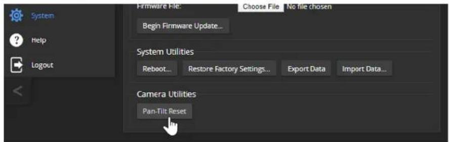
Restoring Factory Default Settings
This returns the device to its original state. If you export the device's configuration before restoring factory defaults, you will be able to restore the room label, time zone information, and home information by importing the configuration afterward.
Note
Because restoring factory defaults returns the product to a "like new" condition, you will need to initial device set-up again if you restore factory defaults.
From the web interface: Log on using the admin account, go to the System page's Firmware tab, and select Restore Factory Settings.
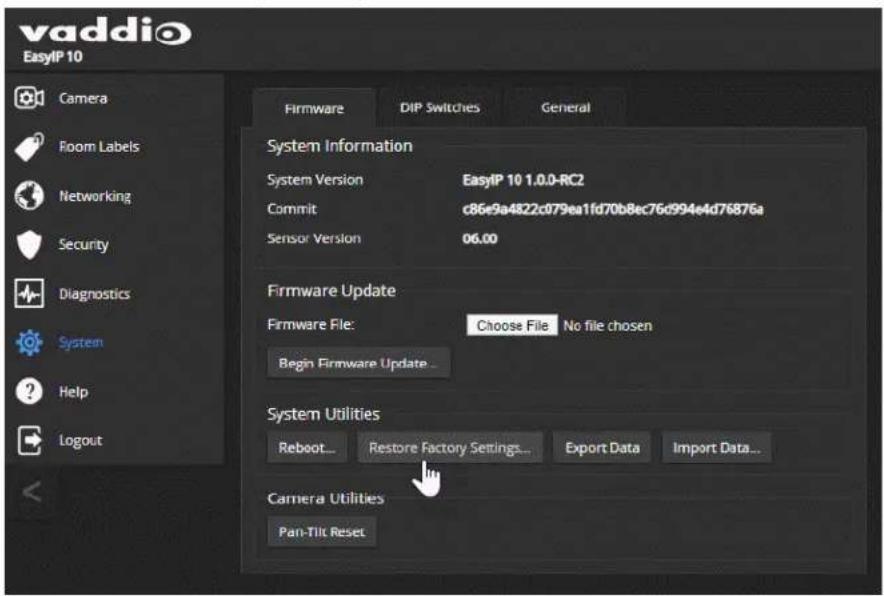
From the Vaddio Deployment Tool: Locate the device, select it in the Name column to open its detail page, and select Restore Factory Defaults from the Controls list.

This tool is available as a free download at https://info.legrandav.com/VaddioDeploymentTool.
From the device (EasyIP Decoder only): Press and hold the IP address button while disconnecting and then reconnecting the network/PoE+ cable.
Contacting Vaddio Technical Support
HELP PAGE, ANY VADDIO DEVICE
If you can't resolve an issue using your troubleshooting skills (or the Troubleshooting table in this manual), we are here to help.
You'll find information for contacting Vaddio Technical Support on the Help screen.
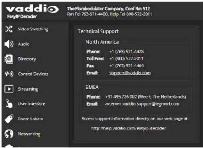
Viewing Diagnostic Logs
DIAGNOSTICS PAGE, EACH EASYIP DEVICE
If you encounter a problem that you can't solve, your Vaddio technical support representative may ask you to download and email the event log file available from the Diagnostics screen.
Note
The log may include large numbers of internal events even when no errors have occurred. Rebo generates over 100 log entries.
![vaddio EasyP Decoder The Flombodulator Company, Conf Rm 512 Rm Tel 763-971-4400, Help Tel 800-572-2011 USB 3.0 Stream Resolution: 1000p USB 3.0 Stream FPS: 30 Muse Muse Standby Logout Video Switching Audio Directory Control Devices Streaming User Interface Room Labels Networking Security Diagnostics System Help Logout Diagnostics Jan 8 14:19:19 vaddio-easyip-decoder-8B-1F-12-50-01-12 kernel: [ 0.95321] lldphy: MACI_mtl_bust_proboo Jan 8 14:19:19 vaddio-easyip-decoder-8B-1F-12-50-01-12 kernel: [ 1.058718] mach c000000.ethercact ethno: Cadmcc GPN rev 8x00402018E ot 8x0040000 (irg 30) Jan 8 14:19:19 vaddio-easyip-decoder-8B-1F-12-50-01-12 kernel: [ 1.666568] Marvell RAFISIA eRMMDB8.ethernet-7f7f7f7f7c: attached PHY driver [Marvell A8] Jan 8 14:19:19 vaddio-easyip-decoder-8B-1F-12-50-01-12 kernel: [ 1.975374] I2C /dev entries driver Jan 8 14:19:19 vaddio-easyip-decoder-8B-1F-12-50-01-12 kernel: [ 1.875744] cdro-l2lc c0004000.llc: 362 kHz mio c0004000 irq 23 Jan 8 14:19:19 vaddio-easyip-decoder-8B-1F-12-50-01-12 kernel: [ 1.666432] cast_jpeg 44888888...cast_jpegder_lrc_new: Cast JPEB driver loaded in decode mob Jan 8 14:19:19 vaddio-easyip-decoder-8B-1F-12-50-01-12 kernel: [ 1.996240] sdxtL secure digital host controller interface driver Jan 8 14:19:19 vaddio-easyip-decoder-8B-1F-12-50-01-12 kernel: [ 1.102391] sdxtL copyright(c) Pierre Osman Jan 8 14:19:19 vaddio-easyip-decoder-8B-1F-12-50-01-12 kernel: [ 1.368737] sdxtL-piltns; SSHT platform and CF driver helper Jan 8 14:19:19 vaddio-easyip-decoder-8B-1F-12-50-01-12 kernel: [ 1.746538] MMCO: SOFC controller on gpioWWWmc [exiWWWWmc] using OWA Jan 8 14:19:19 vaddio-easyip-decoder-8B-1F-12-50-01-12 kernel: [ 1.787896] ledrig-cput registered to indicate operation on CPU Jan 8 14:19:19 vaddio-easyip-decoder-8B-1F-12-50-01-12 kernel: [ 1.595843] PF conductrock version 6.5.0 (6/92 buckets, 3/768 max) Jan 8 14:19:19 vaddio-easyip-decoder-8B-1F-12-50-01-12 kernel: [ 1.267264] lp_tables: (c) zoom.jmm netfilter core team Jan 8 14:19:19 vaddio-easyip-decoder-8B-1F-12-50-01-12 kernel: [ 1.267998] Initializing X-FAM netlink socket Jan 8 14:19:19 vaddio-easyip-decoder-8B-1F-12-50-01-12 kernel: [ 1.232337] NET: Registered protocol family i7 Jan 8 14:19:19 vaddio-easyip-decoder-8B-1F-12-50-01-12 kernel: [ 1.367346] MBSIP: DRLIQ/VLAN Support vi.8 Jan 8 14:19:19 vaddio-easyip-decoder-8B-1F-12-50-01-12 kernel: [ 1.333733] Registering SWP/SWP emulation handler Jan 8 14:19:19 vaddio-easyip-decoder-8B-1F-12-50-01-12 kernel: [ 1.333333] input: gpio_keys ss /devices/36o/gpio_keys/input/input/ Jan 8 14:19:19 vaddio-easyip-decoder-8B-1F-12-50-01-12 kernel: [ 1.394438] ALSA device list: Jan 8 14:19:19 vaddio-easyip-decoder -BB_1F_ - - - - - - - - - - - - - - - - - - - - - - - - - - - - - - - - - - - - - - - - - - - - - - - - - - - - - Jan 8 14:19:19 vaddio-easyip-decoder-BB_1F_ - - - - - - - - - - - - - - - - - - - - - - - - - - - - - - - - - - - - Jan 8 14:19:24 vaddio-easyip-decoder-BB_1F_ - - - - - - - - - - - - - - - - - - - - - - - - - - Jan 8 14:19:24 vaddio-easyip-decoder-BB_1F_ - - - - - - - - - - - - - - - - Jan 8 7.433356 random crng init'done Jan 8 7.433356 random crng init'done Jan 8 7.433356 random crng init'done Jan 8 7.433356 random crng init'done Jan 8 7.433356 random crng init'done Jan 8 7.433356 random crng init'done Download Refresh Clear Restore Auto Refresh](/content/2026/06/1147987/images/6fe013a7106e001985a78bf7b4c5e2ec64781eceea9e78fe267f9a114744f45a.jpg)
Operation, Storage, and Care
For smears or smudges on the product, wipe with a clean, soft cloth. Use a lens cleaner on the lens. Do not use any abrasive chemicals.
Keep this device away from food and liquids.
Do not operate or store the device under any of the following conditions:
■ Temperatures above 104^ F ( 40^ C) or below 32^ F ( 0^ C)
■ High humidity, condensing or wet environments
■ Inclement weather
■ Severe vibration
■ Under the sea, in an octopus's garden
■ Dry environments with an excess of static discharge
Do not attempt to take this product apart. There are no user-serviceable components inside.
Glossary
AEC
Acoustic echo cancellation. Audio processing that subtracts the far-end (speaker) audio from the sound that your microphone picks up.
auto white balance
A setting that allows the camera to manage color adjustments automatically.
backlight compensation
A setting that reduces contrast to adjust for bright light behind the main subject of the shot.
Camera ID (setting)
Specifies which of the IR remote's three frequencies the camera responds to. Use the Camera Select buttons on the remote to change frequency.
channel
A signal from a single source.
chroma
A setting that adjusts color intensity.
detail
A setting that adjusts image sharpness. If detail is set too low, the image may appear unrealistically smooth.
DHCP
Dynamic Host Configuration Protocol. A network management protocol that assigns an IP address to a device automatically when it is connected to the network.
DIP switches
An array of switches designed for installation on a circuit board. (DIP = Dual Inline Package; refers to the physical form.) Our web interface has virtual ones because we miss the real ones.
EasyMic
Vaddio's proprietary connectivity standard for conferencing microphones.
echo cancellation
Audio processing that subtracts the far-end (speaker) audio from the sound that your microphone picks up.
far end
(conferencing) A location in the conference other than the one where you are. Far-end video is what you typically see in a conference – the people at the other end of the call.
Field of View (FOV)
How wide the video image is. Vaddio measures horizontal field of view. Some manufacturers use diagonal field of view, which yields a bigger number for the same actual image area. Tilt your head to one side and diagonal FOV will make sense.
flombodulator
A technically complex item the name of which you can't recall at the moment.
flow (Dante)
One to four channels that can be routed from device to device. Channels remain separate within the flow. For example, left and right audio channels can be part of the same flow.
frame rate
The number of output video frames per second. Different outputs (such as the IP stream and the USB stream) may use different frame rates. For streaming, higher frame rates use more bandwidth.
full-duplex
Simultaneous two-way (or multi-way) audio; conference participants at the near end can talk and still hear the participants at the far end(s), as in a face-to-face meeting.
gamma
A setting that adjusts the range (gray density) between bright areas and shadows.
HID audio controls
(Human Interface Device) Controls to enable conference participants to use the conferencing client to control the audio.
home (camera)
The settings to which the camera returns after a reboot or on exiting standby mode. Depending on the camera's capabilities, home may include zoom, color and lighting settings, and pan/tilt position.
home button (microphone)
A One Touch trigger control on a tabletop microphone. The button can be associated with one macro in momentary mode, or two macros in latching mode.
HTTP
HyperText Transfer Protocol. The magic that makes websites work.
HTTPS
HyperText Transfer Protocol Secure. The magic that uses encryption to make websites work securely. See SSL certificate for more information.
IP address
Where a given device is on the IP network, logically. The IP address enables the network to route data to the right device – and that's the reason IP address conflicts are bad.
IP address conflict
Two or more devices attempting to use the same IP address on a network. Results are unpredictable but never good. You don't need to worry about this if you're not using static IP addresses.
LED
Light-Emitting Diode. An indicator light.
macro
A defined sequence of commands that a device performs in response to a trigger event.
multicast flow (Dante)
A flow that can be routed to all receiving devices in the system.
near end
(conferencing) Your location in a conference. When you mute the video, your camera stops sending near-end video.
NTP
Network Time Protocol. Ensures that NTP-enabled devices on the network all show the same system time, so timestamps are accurate.
pairing
The process of "teaching" two specific devices to recognize each other. Pair cameras to the EasyIP Decoder on its Directory page.
PIP
Picture-in-picture. A small image, typically from the near end, displayed with the main image in a call.
PoE, PoE+, PoE++
Power over Ethernet; a means of powering a device using its network connection. Requires a PoE (+) (++) switch or a mid-span power injector. PoE+ and PoE++ deliver more power than PoE.
preset
A stored camera position. Contains pan, tilt, and zoom position; may also include color settings.
RCLB
Really Cool Logo Badge. A visual cue that the device is a genuine Vaddio product. Accept no substitutes!
resolution
- The image size. For Vaddio cameras, resolution is expressed in terms of digital TV standards, with 1080p being the default in most cases. Resolution and frame rate are set together on Vaddio cameras.
- The thing that usually flies out the window by January 10th.
Richard
The reason there are cats (well, pictures of cats) in this manual.
soft conferencing client
A conferencing application (such as Zoom, Google Hangouts, or Skype for Business) that uses a computer rather than requiring a conferencing codec.
SSL certificate
A file used with HTTPS proving that a web page really originates from its purported source. If you enable or require HTTPS on a camera or other device without installing an SSL certificate, your browser will pop up security warnings when you try to browse to the device's web interface.
trigger
An event, such as pressing the Home button on a connected TableMIC, that can be associated with a macro (defined command sequence). Devices that originate trigger events are sometimes called triggers or trigger devices.
UAC drivers
(Universal Audio Class) Standard USB audio drivers used by Vaddio conferencing products with audio capabilities.
UCC, UC conferencing
Unified Communications Conferencing; refers to soft-client conferencing (such as Zoom or Skype for Business) using a computer with USB-connected peripherals.
unicast flow (Dante)
A flow that can only be routed to one receiving device.
USB 2
An older, lower-speed USB protocol; good for audio but offers lower maximum resolutions for video conferencing. USB 2 products can be connected to USB 2 or USB 3 ports on your computer.
USB 3
A high-speed USB protocol, capable of handling high-quality video and audio as in conferencing applications. USB 3 products should be connected to USB 3 ports; performance may be degraded otherwise.
USB playback
Audio from other sites (far-end audio) in a conference call.
USB record
Audio from your site (near-end audio) in a conference call.
UVC drivers
(Universal Video Class) Standard USB video drivers used by Vaddio cameras. They're the reason your computer doesn't have to stop and download a driver when you connect your new Vaddio USB camera to it.
UVC extensions
Controls in UVC drivers to allow participants at the far end of a conference to control your camera, if it processes UVC commands. The administrator may choose to disable these.
Compliance and Conformity Statements
Compliance testing was performed to the following regulations:
| FCC Part 15 (15.107, 15.109), Subpart B Class A | |
| ICES-003, Issue 54: 2012 Class A | |
| EMC Directive 2014/30/EU Class A | |
| EN 55032: 2015 Class A | |
| EN 55024: November 2010 Class A | |
| IEC 60950-1:2005 (2nd Edition); Am 1: 2009 + Am 2: 2013 Safety | |
| EN 60950-1: 2006 + A11: 2009 + A1: 2010 + A12: 2011 + A2: 2013 Safety | |
| IEC 62368-1:2014 (2nd Edition) Safety |
FCC Part 15 Compliance
This equipment has been tested and found to comply with the limits for a Class A digital device, pursuant to Part 15, Subpart B, of the FCC Rules. These limits are designed to provide reasonable protection against harmful interference when the equipment is operated in a commercial environment. This equipment generates, uses, and can radiate radio frequency energy and, if not installed and used in accordance with the instruction manual, may cause harmful interference to radio communications. Operation of this equipment in a residential area is likely to cause harmful interference in which case the user will be required to correct the interference at his/her own expense.
Operation is subject to the following two conditions: (1) This device may not cause interference, and (2) This device must accept any interference including interference may cause undesired operation of the device.

Changes or modifications not expressly approved by Vaddio can affect emission compliance and could void the user's authority to operate this equipment.
ICES-003 Compliance
This digital apparatus does not exceed the Class A limits for radio noise emissions from digital apparatus set out in the Radio Interference Regulations of the Canadian Department of Communications.
This product has been evaluated for Electromagnetic Compatibility under the EMC Directive for Emissions and Immunity and meets the requirements for a Class A digital device. In a domestic environment this product may cause radio interference in which case the user may be required to take adequate measures.
Standard(s) To Which Conformity Is Declared:

EMC Directive 2014/30/EU
EN 55032: 2015 – Conducted and Radiated Emissions
EN 55024: November 2010 – Immunity
IEC 60950-1: 2005 (2nd Edition); Am 1: 2009 + Am 2: 2013 – Safety
EN 60950-1: 2006 + A11: 2009 + A1: 2010 + A12: 2011 + A2: 2013 - Safety
IEC 62368-1: 2014 (2nd Edition) – Safety
Photo Credits
This guide may include some or all of these photos.
European Space Agency (ESA) astronaut Samantha Cristoforetti, a Flight Engineer with Expedition 42, photographs the Earth through a window in the Cupola on the International Space Station
By NASA - https://blogs.nasa.gov/ISS_Science_Blog/2015/03/06/women-in-space-part-two-whats-gender-got-to-do-with-it/, Public Domain, https://commons.wikimedia.org/w/index.php?curid=38834990
Carl Sagan, Bruce Murray, Louis Friedman (founders) and Harry Ashmore (advisor), on the occasion of signing the papers formally incorporating The Planetary Society
By credit NASA JPL - JPL, Public Domain, https://commons.wikimedia.org/w/index.php?curid=1180927
Main Control Room / Mission Control Room of ESA at the European Space Operations Centre (ESOC) in Darmstadt, Germany
By European Space Agency - ESOC flickr, Credit: ESA - Jürgen Mai, CC BY-SA 3.0-igo, https://commons.wikimedia.org/w/index.php?curid=36743173
Expedition 42 on orbit crew portrait, International Space Station, Mar. 7, 2015 – Barry Wilmore (Commander) Top, Upside down, to the right cosmonaut Elena Serova, & ESA European Space Agency Samantha Cristoforetti. Bottom center US astronaut Terry Virts, top left cosmonauts Alexander Samokutyaev and Anton Shkaplerov.
By NASA - https://www.flickr.com/photos/nasa2explore/16166230844/, Public Domain, https://commons.wikimedia.org/w/index.php?curid=38931301
European Space Agency astronaut Luca Parmitano, Expedition 36 flight engineer, outside the International Space Station
By NASA - http://spaceflight.nasa.gov/gallery/images/station/crew-36/html/iss036e016704.html, Public Domain, https://commons.wikimedia.org/w/index.php?curid=27263573
Chris Cassidy, Luca Parmitano, and Karen Nyberg, ISS, 2013. Photo Credit: NASA
Nicolas Altobelli, Rosetta Scientist at ESA's European Space Astronomy Centre, Villanueva de la Cañada, Madrid, Spain
By European Space Agency - Nicolas Altobelli talks to the media, CC BY-SA 3.0-igo, https://commons.wikimedia.org/w/index.php?curid=36743144
Andrea Accomazzo, ESA Rosetta Spacecraft Operations Manager, providing a live update from the Main Control Room at ESA's European Space Operations Centre, Darmstadt, Germany during the Rosetta wake-up day.
By European Space Agency - Live update from the Main Control Room, CC BY-SA 3.0-igo, https://commons.wikimedia.org/w/index.php?curid=36743150
Sleeping goose
By ladypine - Own work, CC BY-SA 3.0, https://commons.wikimedia.org/w/index.php?curid=1695227
By Rick Dikeman - Image:Wayne Gretzky 1997.jpg, CC BY-SA 3.0,
https://commons.wikimedia.org/w/index.php?curid=945698
Photo AS11-40-5948, Aldrin assembles seismic experiment, by National Aeronautics and Space Administration, courtesy of the NASA History Office and the NASA JSC Media Services Center Author's own cats, photos by author, you're welcome.
Index
A
access 75
front panel 75
admin password 31
changing 31
AEC 44-45, 52
AGC (automatic gain control) 53-55, 57
Ambient Noise (audio setting) 53
anatomy of the camera 9-10
anatomy of the decoder 7
anatomy of the mixer 8
API 118, 123, 128, 132, 137, 139-144
RS-232 (VISCA) 137, 139-144
Telnet 118
audio 7-8, 50-51, 53-55, 57-63, 101, 104-105, 127-128
adjustments 54-55, 57-58, 60-61, 63, 104-105
controls 50, 53-55, 57-60
crosspoint gain 63, 128
delay 61
matrix, editing 62
muting 50, 101, 104-105, 127
operator controls 104-105
ports 7-8
routing 62, 128
volume 51, 127
Audio page (web) 50-55, 59-62
auto focus 89, 114
auto iris 83, 116-117
auto white balance 83, 86, 116-117
B
backing up a configuration 92
backlight compensation 83, 85, 116-117
baud rate 13-14
behavior on power-up 20
blue gain 83, 86, 116-117
browser 21, 25
compatibility 21
security warnings 25
buttons and indicators 7-8
C
cable 7-10, 12-14
connectors 7-10, 12
RS-232 pin-out 13-14
calibration fault, correcting 133, 151
Camera ID (setting) 77
camera mount 18-19
Camera page (web) 82
camera select 97-98
camera selection (remote) 79, 99
cameras 12, 35, 37, 39, 64-65, 102-103, 145, 147
accessing from the EasyIP Decoder 35, 37
adding to the directory 35
connection status 35, 37
controlling from the EasyIP Decoder 64-65
manual control 103
moving to presets 102
pairing to the EasyIP Decoder 35
pairing to the EasyIP Mixer 37
placement 12
selecting 64-65
specifications 145, 147
unpairing 39
capabilities 3, 145, 147
CCU scenes 82, 84, 118
custom 84, 118
recalling 118
CCU settings 85-86, 115-117
ceiling-mounted cameras 19, 78
Chairman Override (setting) 54
cheat sheet 29, 85-86, 97-98
color adjustment 86
lighting and image quality 85
web interface 29
chroma setting 83, 85-86, 116-117
cleaning 155
color codes for status light 151
color settings 82-84, 86, 116-117
Color Space (setting) 65-66
command history 136
command set, RS-232 (VISCA) 137, 139-144
commands 123, 128, 132
compatibility, browsers 21
Compressor (setting) 60
conferencing 48
configuration, saving or restoring 92
connection diagram 15-17
connectors 7-10
Control Devices page (web) 69-71, 73-74
controls available to non-admin user 100
crosspoint gain 63, 128
custom CCU scenes 84
custom home position 79
D
daisy-chaining Dante microphones 45-46
damage, preventing 4-6, 11-14
Dante Controller (application) 40-46
Dante devices 40-46
"identify" function 41
discovering IP address 41
renaming 42
routing audio 42
default settings, restoring 134, 153
Delay (setting) 61
detail setting 83, 85, 116-117
diagnosing issues 133, 149-151
diagnostic logs 33, 154
timestamps 33
Diagnostics page (web) 154
diagram, connection 15-17
directional controls 97-98, 103
directory 35, 39
adding cameras 35
editing 35
removing cameras 39
Directory page (web) 35, 39
disabling the front panel controls 75
dynamic range 54-55, 57-58
dynamic range (audio) 53, 59
E
Easy PEQ settings 53, 57-58
EasyIP basics 2
echo cancellation 52-55, 58
equalizer 53, 55, 59-60
F
factory defaults, restoring 134, 153
far-end camera control 49
fault isolation 133, 149-151
filters, high-pass and low-pass 55
firmware update 93-95
firmware version 135
flow (Dante) 43-46
multi-channel 45-46
multicast 43-44
unicast 43
focus 89, 97-98, 114
front panel 75
locking 75
G
gain 63, 83, 85-86, 128
audio, crosspoint 63, 128
blue 83, 86
iris 85
red 83, 86
gamma setting 83, 85
getting help 154
graphics 66-68, 107
activating 107
library 66-67
mask type 66-67
placement 66-67
renaming 67
selecting 107
Graphics Library page (web) 66-68
guest access 31
H
HDMI In port 8
HDMI Out port (camera) 10
HDMI Out port (EasyIP Mixer) 8
HDMI output resolution 90
Help page (web) 154
high-pass filter (microphone adjustment) 55
home position 79, 103, 110
custom 79
hostname 33
HTTP 32
enabling 32
HTTPS 25
browser warnings 25
|
Identify (device function) 41
Image Flip (setting) 78
importing a configuration 92
inactive sessions (web interface) 31
indicator light 7-10, 79, 121, 151
behavior 79, 121
color scheme 79
enabling/disabling 79
meaning of colors 7, 9-10, 151
information, conference room 34
initial device set-up 21-24
using Vaddio Deployment Tool 24
installation 15-19
camera 19
camera mount 18
inverted 19
typical 15-17
inverted installation 19, 78
IP address 7-8, 24, 26-27, 41, 97-98, 100
camera, discovering 24, 100
camera. discovering 27
Dante device, discovering 41
decoder, discovering 7
EasyIP Decoder, discovering 24, 26, 100
EasyIP Mixer, discovering 8
IP streaming 130
settings 130
IR cut filter 121
IR frequency selection (remote) 79, 99
IR remote 77, 79, 97-99
IR Settings (Camera ID) 77
iris settings 85, 116-117
K
keying 66-68, 107
graphics library 66-68
sources 66
L
labels, room 34
LED control 79, 121
light, status indicator 79, 121, 151
behavior 79, 121
color scheme 79
enabling/disabling 79
meaning of colors 151
lighting settings 82, 116-118
lip sync 61
location of the camera 12, 34
locations of connectors 7-10
locking the front panel 75
log files 154
low-light adjustment 121
low-pass filter adjustment (microphones) 55
low-power (standby) state 101, 119, 121, 131
low-power state 132
M
macros 69-71, 73
assigning to triggers 73
creating and editing 70
testing 71
manual focus 89, 97-98, 114
matrix, audio routing 62-63
media player 26, 48
mic boost 53-55
Mic Boost (audio setting) 53, 57-58
microphone pass-through (Dante) 45-46
microphones 44-46, 50, 52-53, 94-95, 101, 104-105, 127
adjusting 53
adjusting volume 104-105
filter adjustments 55
firmware update 94-95
muting 50, 101, 104-105, 127
PEQ (parametric equalizer) 55
powering 52
minimum requirements, EasyIP system 15-17
motor calibration 133, 151
mount 18-19
installing 18
mounting the camera 19
multicast flow (Dante) 43-44
muting 50-51, 101, 104-105, 122, 127
audio inputs 50-51, 127
audio outputs 51, 127
microphones 104-105, 127
speakers 104-105, 127
video 122
N
network configuration 33, 130
current 130
network port 7-10
Networking page (web) 33
noise cancellation 53-55, 58
NTP server 33
0
One Push White Balance 86
operating environment 11, 155
operator controls 100-101, 104-107
P
packing list 4-6
page 31-35, 37, 39, 48-55, 59-62, 64-71, 73-75, 82, 154
Audio 50-55, 59-62
Camera 82
Control Devices 69-71, 73-74
Diagnostics 154
Directory 35, 39
Graphics Library 66-68
Help 154
Networking 33
Room Labels 34
Security 31-32
Streaming 48
System 49, 75
User Interface 75
Video Inputs 37, 39, 65
Video Outputs 66
Video Switching 64-65
pairing 35, 37, 42-43, 45
to cameras 35, 37
to Dante devices 42-43, 45
pan 87-88, 97-98, 103, 111
direction 88
speed 87, 111
pan/tilt recalibration 133, 151
parametric equalizer 53
part numbers 4-6
passwords 31
PEQ (parametric equalizer) 55
performance specifications 145, 147
phantom power 52
physical and environmental specifications 145, 147
pin-out, RS-232 13-14
ping command 133
PIP 17, 66, 106, 123
layout 66, 106
source 66, 106, 123
source, from EasyIP camera 17
PIP screen 106
PoE+ port 7-10
point light compensation 83, 85
power down 132
power on/power off 20, 97-98, 119, 131
power up 132
powering microphones 52
precautions 4-6, 11
for operating the system 11
presets 79, 81, 97-98, 102, 115
clearing 98
moving to 102, 115
renaming 81
setting 79, 98, 115
product capabilities 3, 145, 147
puffy logo badge 7-8
Q
quick reference 28-29, 47, 53, 85-86, 97-98
audio adjustments 53
new device system administration 28
remote control 97
system behaviors 47
Vaddio IR Remote Commander 98
web interface 29
R
ready state 119, 131-132
rebooting 96, 134
recalibration, pan and tilt 133, 151
red gain 83, 86, 116-117
remote control 77, 79, 97-99
removing cameras from the directory 39
requirements 2, 11-12, 15-18
EasyIP system 2
installation 11-12, 15-18
network 11
reset 133, 151 See also rebooting; restoring default settings
pan and tilt motors 133, 151
resolution, HDMI 90
restoring a configuration 92
restoring default settings 134, 153
Reverberant Room (audio setting) 53
RJ-45 connectors 12
room information 34
Room Labels page (web) 34
routing audio 43, 45-46, 62
using Dante Controller 43, 45-46
RS-232 13-14
cable pin-out 13-14
communication settings 13-14
RS-232 commands 137, 139-144
setting values 142-143
RS-232 port 8, 10
S
saving a configuration 92
scenes, CCU 82
storing 84
Scott 82
Security page (web) 31-32
self-signed certificate 25
settings, default, restoring 134, 153
shelf-mounted cameras 19
shelf, camera mount 18
site requirements 12
software update 93-95
solving problems 149-151
source 62
audio 62
speaker 59
speakers 60-61, 104-105, 127
adjusting for differing speech volumes 60
adjusting volume 104-105
equalizer 60
muting 104-105, 127
synchronizing audio with video 61
specifications 145, 147
Speech Enhancement (audio setting) 53
Speech Lift (setting) 54
speed 87, 97-98, 111-114
focus 114
Global Preset Non-Tri-Sync, setting 87
manual, setting 87
pan 87, 111
tilt 87, 112
zoom 87, 97-98, 113
SSL certificate 32
standby (low-power) state 119, 121, 131
standby state 75, 101, 132
behavior of connected devices 75
status light 7-10, 121, 151
behavior 7, 9-10, 121
meanings of colors 151
storage environment 155
storing a configuration 92
stream viewer 48
streaming 48, 130
configuring 48
settings 48, 130
Streaming page (web) 48
supported web browsers 21
switch settings 19
synchronizing audio with video 61
syntax help, Telnet commands 136
System page (web) 49, 75
system time 33
T
tablet 23
technical specifications 145, 147
technical support 154
Telnet 32
enabling 32
Telnet API 118
Telnet commands 109-117, 119, 121-124, 129-131, 133-136
syntax help 109, 136
typographical conventions 109
Telnet session 109, 136
ending 136
history 136
temperature, operating and storage 155
testing 71, 74
macros 71
triggers 74
third-party control 109
tilt 87, 97-98, 103, 112
speed 87
time zone 33
trigger command, failure to execute 74
trigger devices 69
trigger ports 8
triggers 69, 73-74, 131
defining 73
deleting 73
testing 74
troubleshooting 133, 149-151
U
unicast flow (Dante) 43
unpairing 39
update 93-95
uploading graphics files 66-67
USB port 7-8
USB stream format 49
USB streaming 48
configuring 48
User Interface page (web) 75
user password 31
changing 31
V
Vaddio Dante Interface Application 22, 56-57, 94-95
Vaddio Deployment Tool 22, 24
accessing discovered devices 24
check for the latest version 24
features 22
initial device set-up 24
Vaddio Device Controller 22-23
features 22
Vaddio IR Remote Commander 97-98
version, firmware 135
video 65, 101, 106, 123-124
input source selection 123
input type 124
inputs 65
muting 101
PIP, configuring 106
Video Inputs page (web) 37, 39, 65
video mute 65, 101, 122
Video Outputs page (web) 66
Video Switching page (web) 64-65
VISCA commands 137, 139-144
visual packing list 4-6
visual parts identification 7-10
volume 104-105
controls 104-105
volume controls 51, 127
W
wall mount 18
installing 18
warranty 11
web browsers supported 21
web interface 21, 23-27, 31-35, 37, 39, 48-53, 59-62, 64-71, 73-75, 82, 100, 154
accessing 23-24, 26, 100
Audio page 50-53, 59-62
Camera page 82
Control Devices page 69-71, 73-74
Diagnostics page 154
Directory page 35, 39
Graphics Library 66-68
Help page 154
manual access 25-27
Networking page 33
Room Labels page 34
Security page 31-32
Streaming page 48
Switch to HTTPS message 25
System page 49, 75
User Interface page 75
Video Inputs 65
Video Inputs page 37, 39
Video Outputs page 66
Video Switching page 64-65
wide dynamic range setting 85
Z
zoom 87, 97-98, 103, 113
speed 87, 97-98, 113
Vaddio is a brand of Legrand AV Inc. · www.legrandav.com · Phone 800.572.2011 / +1.763.971.4400 · Fax +1.763.971.4464 · Email av.vaddio.support@legrand.com ·
Visit us at www.legrandav.com for firmware updates, specifications, drawings, manuals, technical support information, and more.
©2020 Legrand AV Inc.
Vaddio is a registered trademark of Legrand AV Inc. Audinate®, the Audinate logo and Dante® are registered trademarks of Audinate Pty Ltd. All other brand names or marks are used for identification purposes and are trademarks of their respective owners. All patents are protected under existing designations. Other patents pending.
A brand of legrand®
Commercial AV Brands Chief | Da-Lite | Middle Atlantic | Projecta | Vaddio
vaddio®
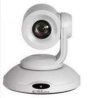
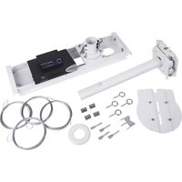
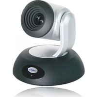
- EasyIP Systems
- Contents
- Complete Manual for EasyIP Systems
- Overview
- What's in this Guide
- This guide covers
- The EasyIP Ecosystem
- EasyIP Decoder
- EasyIP Mixer
- EasyIP Cameras
- EasyIP Switch
- EasyIP Decoder Features
- EasyIP Mixer Features
- EasyIP 10 Camera Features
- EasyIP 20 Camera Features
- Unpacking the EasyIP System Components
- EasyIP Decoder AV-over-IP Switching USB Endpoint
- EasyIP Mixer AV Switcher
- EasyIP 10 AV-over-IP PTZ Camera
- Caution
- EasyIP 20 AV-over-IP PTZ Camera
- A Quick Look at the EasyIP Family
- Front View
- Back View
- EasyIP 10 Camera
- EasyIP 20 Camera
- Installation
- Note
- Don't Void Your Warranty!
- Before You Start
- Before Installing Cameras
- Cabling Notes
- Pro Tip
- RS-232 Serial Communication Settings and Port Pin-outs
- RS-232 connector pin-out:
- Basic Connections - EasyIP Decoder
- Basic Connections - EasyIP Mixer
- Basic Connections – EasyIP Mixer with HDMI Input from EasyIP 20 Camera
- Installing the Wall Mount for the Camera
- Installing the Camera
- About Ceiling-Mounted Cameras
- Powering Up the EasyIP System
- Initial Set-Up and Access to Administrative Controls
- Browser Support
- Initial Device Set-up Process Overview
- About the Vaddio Device Controller
- About the Vaddio Deployment Tool
- Access and Initial Device Set-Up Using the Vaddio Device Controller
- To complete the initial device set-up with the Vaddio Device Controller:
- Initial Device Set-Up and Access Using the Vaddio Deployment Tool
- To complete the initial device set-up with the Vaddio Deployment Tool:
- To access EasyIP devices' web interfaces from the Vaddio Deployment Tool:
- Manual Access and Initial Device Set-Up
- Initial Access to the Web Interface
- Access the Web Interface of an EasyIP Decoder or EasyIP Mixer Manually
- To discover the device's IP address:
- To access the device's web interface:
- Access the Web Interface of an EasyIP Camera Manually
- To discover a camera's IP address from an EasyIP Decoder:
- To discover a camera's IP address from an EasyIP Mixer:
- Next Steps for New Deployments
- Web Interface Quick Reference
- EasyIP Decoder Basic Operation – Operator's Pages
- EasyIP Mixer Basic Operation – Operator's Pages
- System Administration (All Devices)
- System Behaviors and Operation
- Maintenance and Troubleshooting
- System Administration
- Setting Passwords and Access
- SECURITY PAGE
- Configuring Other Security Settings
- Changing Device Hostnames
- NETWORKING PAGE
- Specifying Time Zone and NTP Server
- Adding Room Information to the Device's Web Interface
- ROOM LABELS PAGE
- Pairing EasyIP Devices
- Locating and Pairing to Cameras on the Network – EasyIP Decoder
- DIRECTORY PAGE
- To add a camera to the directory:
- To change a directory entry:
- To access a camera's web interface:
- Locating and Pairing to Cameras on the Network – EasyIP Mixer
- VIDEO INPUTS PAGE
- To locate cameras on the network:
- Unpairing Cameras
- Using Dante Devices with the EasyIP Mixer
- Locating and Pairing to Dante Devices
- To physically locate Dante devices using the Dante Controller application:
- Other ways to access the Identify function:
- Pairing to More than Two EasyIP or Other Dante Microphones
- About Channels and Flows
- Creating a Multicast Flow
- To define the multicast flow:
- Combining Microphone Channels into Flows
- To route four microphones as two flows:
- Configuring System Behavior
- Configuration Quick Reference
- Configuring Streaming Behavior
- Viewing a Stream
- To view the USB stream:
- Configuring USB Streaming
- STREAMING PAGE
- Configuring the USB Stream Format for Specific Applications
- SYSTEM PAGE
- Configuring Audio Settings
- AUDIO PAGE
- Muting All Audio Inputs Together
- ALL PAGES
- Muting and Controlling Volume Per Input or Output
- To manage individual audio inputs or outputs:
- To mute individual inputs or outputs:
- Enabling Phantom Power to Microphones – EasyIP Mixer
- AUDIO PAGE, ANALOG TAB
- About Echo Cancellation
- Fine-Tuning Microphone Performance - EasyIP Decoder
- To adjust microphones for best far-end audio performance:
- Fine-Tuning Microphone Performance - EasyIP Mixer
- Presentation Adjustments
- Performance Adjustments
- About the Vaddio Dante Interface Application
- Fine-Tuning EasyIP Microphone Performance
- VADDIO DANTE INTERFACE APPLICATION
- Fine-Tuning Speaker Performance - EasyIP Decoder
- Fine-Tuning Speaker Performance - EasyIP Mixer
- Routing Audio - EasyIP Mixer
- AUDIO PAGE, MATRIX TAB
- To specify how the EasyIP Mixer uses a given audio input:
- Working with Video - EasyIP Decoder
- Working with Video - EasyIP Mixer
- Working with the EasyIP Mixer's Video Inputs
- Configuring the EasyIP Mixer's Video Output
- VIDEO OUTPUT PAGE
- Working with Graphics - EasyIP Mixer
- GRAPHICS PAGE
- To upload a graphics file:
- To work with keying layers:
- Setting up Macros and Triggers
- CONTROL DEVICES PAGE
- Writing and Editing Macros
- To define a macro:
- Testing Macros
- CONTROL DEVICES PAGE, MACROS TAB
- To edit an existing macro:
- To create a new macro based on an existing one:
- Assigning Macros to Triggers
- Testing Triggers
- To test a trigger:
- Example: Assigning a Function to the Connected Microphone's Home Button
- VIDEO SWITCHING PAGE, CONTROL DEVICES PAGE
- Tasks to accomplish this:
- Locking the Front Panel Controls - EasyIP Mixer
- USER INTERFACE PAGE
- Configuring System Standby Behaviors
- Configuring and Adjusting Cameras
- Signal-Related Settings
- Inverting the Image for Ceiling-Mounted Cameras
- Setting Cameras to Respond to Different Frequencies
- Selecting the Camera to Control with the Remote
- Indicator Light Behavior
- Setting the Home Position and Other Preset Shots
- CAMERA PAGE
- Renaming Presets
- Initial Lighting and Color Settings - EasyIP 20
- Color and Image Quality Adjustments
- Saving Color and Lighting Settings – EasyIP 20
- Lighting and Image Quality Quick Reference
- Color Adjustment Quick Reference
- Setting the Speeds for Manual Camera Movements
- To set speeds for movements using the arrow buttons:
- Setting the Speeds of Camera Movements to Presets
- To set speeds for movements to presets:
- Setting the Direction for Camera Movements
- Adjusting the Focus
- Setting HDMI Video Output Resolution - EasyIP 20 Camera
- SYSTEM PAGE, GENERAL TAB
- To set HDMI output resolution via the camera's web interface:
- System Maintenance
- Saving (Exporting) or Restoring (Importing) a Configuration
- SYSTEM PAGE, FIRMWARE TAB
- To export a configuration:
- Installing a Firmware Update
- Installing a Firmware Update for a Connected Vaddio EasyMIC Series Microphone – EasyIP Decoder
- SYSTEM PAGE, PERIPHERALS TAB
- Select Begin Firmware Update.
- Installing a Firmware Update for an EasyIP Microphone
- To update EasyIP microphone firmware:
- Rebooting the Device
- Using the Camera's Remote Control
- IR Remote Details
- Storing a Preset Using the Remote
- Clearing a Preset Using the Remote
- Using the Operator's Web Interface
- Quick Steps: Muting and Standby
- Moving the Camera to a Preset Position
- Moving the Camera Manually
- Working with Audio - EasyIP Decoder
- HOME PAGE
- Working with Audio - EasyIP Mixer
- Selecting a PIP Source and Layout - EasyIP Mixer
- Working with On-Screen Graphics – EasyIP Mixer
- To select a graphic:
- Serial Command API
- Notes
- Usage notes:
- Typographical conventions:
- Camera Commands for Cameras and Host Devices
- camera home
- camera pan
- camera tilt
- camera zoom
- camera focus
- camera preset
- camera ccu get
- camera ccu set
- camera ccu scene
- camera standby
- Camera Commands Direct to Cameras Only
- camera ptz-position
- CAMERA ONLY
- camera led
- camera icr
- Video Management Commands
- video mute
- video type
- Audio Management Commands
- Audio Channels Available on the EasyIP Decoder
- Audio Channels Available on the EasyIP Mixer
- Communication and Network Commands
- camera authenticate
- EASYIP DECODER, EASYIP MIXER
- camera comm host
- streaming settings get
- network settings get
- Control and Power Commands
- trigger
- system standby
- Maintenance and Troubleshooting Commands
- camera recalibrate
- network ping
- system reboot
- system factory-reset
- version
- Telnet Information and Session Management Commands
- history
- help
- exit
- RS-232 Serial Commands for EasyIP 20 Cameras
- Specifications
- Camera Specifications
- Troubleshooting and Care
- Status Indicator Light
- Correct a Camera Motor Calibration Error
- Note:
- Restoring Factory Default Settings
- Contacting Vaddio Technical Support
- Viewing Diagnostic Logs
- Operation, Storage, and Care
- Glossary
- AEC
- auto white balance
- backlight compensation
- Camera ID (setting)
- channel
- chroma
- detail
- DHCP
- DIP switches
- EasyMic
- echo cancellation
- far end
- Field of View (FOV)
- flombodulator
- flow (Dante)
- frame rate
- full-duplex
- gamma
- HID audio controls
- home (camera)
- home button (microphone)
- HTTP
- HTTPS
- IP address
- IP address conflict
- LED
- macro
- multicast flow (Dante)
- near end
- NTP
- pairing
- PIP
- PoE, PoE+, PoE++
- preset
- RCLB
- resolution
- Richard
- soft conferencing client
- SSL certificate
- UAC drivers
- UCC, UC conferencing
- unicast flow (Dante)
- USB 2
- USB 3
- USB playback
- USB record
- UVC drivers
- UVC extensions
- Compliance and Conformity Statements
- FCC Part 15 Compliance
- ICES-003 Compliance
- Photo Credits
- Index
- A
- B
- C
- D
- E
- F
- G
- H
- |
- K
- L
- M
- N
- 0
- P
- Q
- R
- S
- W
- Z
- A brand of legrand®
Brand : Vaddio
Model : EasyIP Ecosystem Base Kit
Category : Video Conferencing System