C-MAP-S - Accessory Havis - Free user manual and instructions
Find the device manual for free C-MAP-S Havis in PDF.


| Product Type | Accessory (Vehicle Mount / Holder) |
| Brand | Havis |
| Model | C-MAP-S |
| Compatibility | Designed for use with Havis docking stations and vehicle consoles |
| Material | High-strength aluminum alloy with corrosion-resistant coating |
| Dimensions (approx.) | 5.0" x 3.0" x 1.5" (127 x 76 x 38 mm) |
| Weight | 0.5 lb (227 g) |
| Mounting Type | Plate with pre-drilled holes for screw or stud mounting |
| Main Function | Provides secure attachment point for electronic devices or accessories |
| Power Source | Passive (no power required; device powers via connected docking station) |
| Cable Management | Integrated slots for routing cables |
| Operating Temperature | -40°F to 185°F (-40°C to 85°C) |
| Water/Dust Resistance | IP54 (splash-proof and dust resistant) |
| Color | Black |
| Warranty | 3-year limited warranty against defects |
| Certifications | RoHS, REACH |
| Included Accessories | Mounting plate, hardware kit (screws, washers) |
| Repairability | No user-serviceable parts; contact Havis for support |
| Cleaning Instructions | Wipe with a soft, damp cloth; do not use abrasive cleaners |
| Storage | Store in a cool, dry place away from direct sunlight |
Frequently Asked Questions - C-MAP-S Havis
User questions about C-MAP-S Havis
0 question about this device. Answer the ones you know or ask your own.
Ask a new question about this device
Download the instructions for your Accessory in PDF format for free! Find your manual C-MAP-S - Havis and take your electronic device back in hand. On this page are published all the documents necessary for the use of your device. C-MAP-S by Havis.
USER MANUAL C-MAP-S Havis
Gooseneck Map Light Installation Instructions
Warning: Please read all instructions and warnings prior to installation of the Gooseneck Map Light.
TOOLS REQUIRED:
Phillips Screw Driver
Wire Cutter
HARDWARE: (Supplied in Kit)
Qty. Description
2 #6 Machine Screw 2 #6 Split Lock Washer
2 #6 Thread Forming Screw 2 #6 Flat Washer
Qty. Description
INSTALLATION:
1. Mounting:
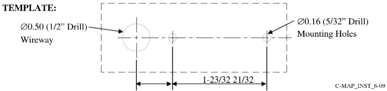
- A drill template is provided on the back of this instruction sheet. Detach the template, position it on the desired location for installation, and mark drill locations.
Caution: Before drilling holes, ensure that the mounting surfaces are clear and that the screws will not damage the internal parts of the console or vehicle.
Caution: Ensure that the Gooseneck Map Light is installed in areas recommended by the vehicle manufacturer—outside of the airbag zone.
- Drill the mounting holes.
- Remove the template prior to installing the fixture. Secure the base of the fixture in position using the supplied machine screws and washers.
- The supplied super clip may be used to secure the gooseneck in position if desired.
Caution: Thread forming screws are supplied for alternate installations requiring the fixture to be mounted from above. If the fixture needs to be disassembled for such installation, please note that this will void your warranty.
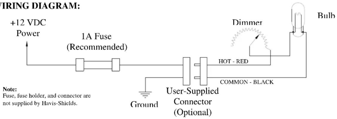
2. Wiring:
- Connect the black lead to the vehicle chassis (Ground.)
- Connect the red lead to power.
Note: It is recommended to install an in-line fuse holder and 1 Amp fuse on the red (hot) lead.
- Test the light for proper operation.
Caution: The Gooseneck Map Light uses a halogen bulb—It can be VERY HOT!
Do not touch the bulb or fixture shroud when it is hot.
3. Operation:
- Power is supplied through a dimmer switch. Turn the knob clockwise to turn on the light and increase brightness, and counterclockwise to dim or turn off power.
Caution: Always turn the dimmer knob gently. Do not force the knob to turn once it stops. - The fixture head has an integral red lens. If desired, slide the lens over the lamp for red light, or slide it toward the stem for white light.
Note: To avoid leaving fingerprints on the lens, use only the tab on the edge of the red lens to slide it.
4. Troubleshooting:
- In the event of improper operation, first check that the dimmer switch is turned all the way on by gently rotating the knob clockwise until it stops.
• Second, check the bulb and replace it if it is burned out. - Third, check the fuse (if installed) and replace it if necessary.
- Finally, use a voltmeter to ensure that the fixture is receiving adequate power. The light requires nominally 12 VDC for correct operation. Correct any faults found.
REPLACEMENT PARTS:
Part # Description
CM93745 Lamp, 5 Watt, Halogen
WIRING DIAGRAM:
Clip Here
Clip Here
Brand : Havis
Model : C-MAP-S
Category : Accessory