DS-2CE16F7T-IT5 - Security Camera Hikvision - Free user manual and instructions
Find the device manual for free DS-2CE16F7T-IT5 Hikvision in PDF.

| Product Type | Security Camera (Turret) |
| Model | DS-2CE16F7T-IT5 |
| Brand | Hikvision |
| Resolution | 2 Megapixels (1920 × 1080) |
| Image Sensor | 1/2.7" Progressive Scan CMOS |
| Minimum Illumination | 0.01 Lux @ (F1.2, AGC ON), 0 Lux with IR |
| Shutter Speed | 1/25 s to 1/50,000 s |
| Lens Type | Varifocal (2.7 – 13.5 mm) |
| Field of View | 105° – 30° (horizontal) |
| IR Distance | Up to 50 m (164 ft) with Smart IR |
| Day/Night | IR Cut Filter with Auto Switching |
| Video Output | 1 HD Analog Output (BNC) |
| Signal System | NTSC / PAL (switchable) |
| Dimensions (Ø × H) | Approx. 110 mm × 97 mm (4.33" × 3.82") |
| Weight | Approx. 450 g (0.99 lb) |
| Power Supply | 12 V DC ± 10% |
| Power Consumption | Max 4 W (with IR on) |
| Weatherproof Rating | IP67 |
| Operating Temperature | -40 °C to +60 °C (-40 °F to +140 °F) |
| Main Functions | True Day/Night, Smart IR, DNR (2D/3D), AGC, BLC, HLC, EXIR 2.0 |
| Mounting Bracket | Included (ceiling/wall mount) |
| Cable Length | Integrated 1.5 m (4.9 ft) BNC+power cable |
| Maintenance & Cleaning | Wipe lens with soft, dry cloth; check cable connections periodically; keep vent hole unblocked |
| Safety | Install on sturdy surface; use proper insulation for outdoor wiring; avoid exposure to extreme heat/corrosive environments |
| Spare Parts & Repairability | Power adapter and mounting bracket available separately; no user-serviceable internal parts |
| General Information | Analog HD (TVI/AHD/CVI/CVBS) compatible, suitable for residential and commercial monitoring, 2-year warranty (subject to terms) |
Frequently Asked Questions - DS-2CE16F7T-IT5 Hikvision
User questions about DS-2CE16F7T-IT5 Hikvision
0 question about this device. Answer the ones you know or ask your own.
Ask a new question about this device
Download the instructions for your Security Camera in PDF format for free! Find your manual DS-2CE16F7T-IT5 - Hikvision and take your electronic device back in hand. On this page are published all the documents necessary for the use of your device. DS-2CE16F7T-IT5 by Hikvision.
USER MANUAL DS-2CE16F7T-IT5 Hikvision
natural_image
Abstract grayscale circular graphic with concentric rings and a central eye-like shape (no text or symbols)TURBO HD D7T Series Bullet Camera
User Manual
UD00387B
www.hikvision.com
User Manual
Thank you for purchasing our product. If there are any quesons, or requests, please do not hesitate to contact the dealer.
This manual applies to the models below:
| Type | Model |
| Type I Camera | DS-2CE16D(F)7T-IT |
| Type II Camera | DS-2CE16D(F)7T-IT1 |
| DS-2CE16D(F)7T-IT3 | |
| DS-2CE16D(F)7T-IT5 |
This manual may contain several technical incorrect places or prinng errors, and the content is subject to change without noce. The updates will be added to the new version of this manual. We will readily improve or update the products or procedures described in the manual.
Privacy Noce
Surveillance laws vary by jurisdicon. Check all relevant laws in your jurisdicon before using all this product for surveillance purpose to ensure that your use of this product conforms.
Regulatory Informaon
FCC Informaon
FCC compliance: This equipment has been tested and found to comply with the limits for a digital device, pursuant to part 15 of the FCC Rules. These limits are designed to provide reasonable protecon against harmful interference when the equipment is operated in a commercial environment. This equipment generates, uses, and can radiate radio frequency energy and, if not installed and used in accordance with the instrucon manual, may cause harmful interference to radio communicaons. Operaon of this equipment in a residential area is likely to cause harmful interference in which case the user will be required to correct the interference at his own expense.
FCC Conditions
This device complies with part 15 of the FCC Rules. Operaon is subject to the following two conditions:
-
This device may not cause harmful interference.
-
This device must accept any interference received, including interference that may cause undesired operaon
EU Conformity Statement

This product and - if applicable - the supplied accessories too are marked with "CE" and comply therefore with the applicable harmonized European standards listed under the Low Voltage Directive 2006/95/EC, the EMC Directive 2004/108/EC.

2002/96/EC (WEEE direcve): Products marked with this symbol cannot be disposed of as unsorted municipal waste in the European Union. For proper recycling, return this product to your local supplier
upon the purchase of equivalent new equipment, or dispose of it at designated collecon points. For more informaon see: www.recyclethis.info.

2006/66/EC (baery direcve): This product contains a baery that cannot be disposed of as unsorted municipal waste in the European Union. See the product documentaon for specic baery informaon. The baery is marked with this symbol, which may include leering to indicate cadmium (Cd), lead (Pb), or mercury (Hg). For proper recycling, return the baery to your supplier or to a designated collecon point. For more informaon see: www.recyclethis.info.
Industry Canada ICES-003 Compliance
This device meets the CAN ICES-3 (A)/NMB-3(A) standards requirements.
1.1 Product Features
This series of camera adopts high performance sensor and advanced circuit board design technology. It features high resolution, low distortion, and low noise, etc. It is suitable for surveillance system and image process system.
The main features are as follows:
● High performance CMOS sensor and high resolution bring high-quality image;
● Low illuminaon, 0.01 Lux @ (F1.2, AGC ON), 0 Lux with IR;
- IR cut Iter with auto switch;
- OSD menu, parameters are congorable;
● Auto white balance and internal synchronizaon;
● SMART IR mode;
- True WDR;
● Advanced 3-axis design meets dierent installaon requirements;
1.2 Overview

This manual applies to two types of bullet cameras.
The overviews of each type are shown in the gures below, please refer to the actual sample.
1.2.1 Overview of Type I Camera
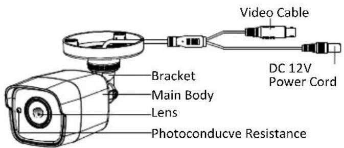
text_image
Video Cable DC 12V Power Cord Bracket Main Body Lens Photoconducve ResistanceFigure 1-1 Overview of Type I Camera
1.2.2 Overview of Type II Camera
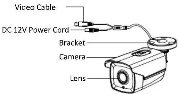
text_image
Video Cable DC 12V Power Cord Bracket Camera LensFigure 1-2 Overview of Type II Camera
Before you start:
- Please make sure that the device in the package is in good condion and all the assembly parts are included.
● Make sure that all the related equipment is power-o during the installaon. - Check the specicaon of the products for the installaon environment.
- Check whether the power supply is matched with your required output to avoid damage.
- Please make sure the wall is strong enough to withstand three mes the weight of the camera and the mounng.
- If the wall is the cement wall, you need to insert expansion screws before you install the camera. If the wall is the wooden wall, you can use self-tapping screw to secure the camera.
- If the product does not funcon properly, please contact your dealer or the nearest service center. Do not disassemble the camera for repair or maintenance by yourself.
2.1 Installaon of Type I Camera

Both wall moung and ceiling moung are suitable for the bullet camera. Ceiling moung will be taken as an example in this secon. You can take steps of ceiling moung as a reference if wall moung is adopted.
2.1.1 Ceiling/Wall Mounng without Gang Box
Steps:
- Aach the drill template (supplied) to the place where you want to x the camera, and then drill the screw holes and the cable hole in the ceiling/wall according to the drill template.
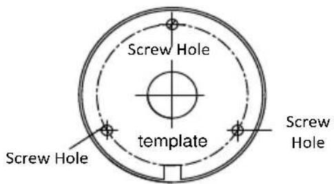
text_image
Screw Hole template Screw Hole Screw HoleFigure 2-1 Drill Template
- Route the cables through the cable hole.
- Secure the camera to the ceiling with the supplied Screws.
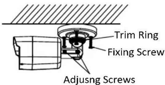
text_image
Trim Ring Fixing Screw Adjusng ScrewsFigure 2-2 Fix the Camera to the Ceiling
- Connect the corresponding cables.
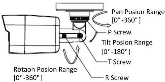
- Adjust the camera according to Figure 2-3 to get an opmum angle.
1). Loosen the P screw to adjust the pan direcon [0°\~360°]. Tighten the screw aer compleng the adjustment.
2). Loosen the T screw to adjust the lt direcon [0^ 180^] . Tighten the screw aer compleng the adjustment.
3). Loosen the R screw and rotate the camera [0^ 360^] to adjust the lens to the surveillance angle. Tighten the screw aer compleng the adjustment.
text_image
Pan Posion Range [0° -360°] P Screw Tilt Posion Range [0° -180°] T Screw Rotaon Posion Range [0° -360°]Figure 2-3 3-axis Adjustment
- Tighten the xing screws and the trim ring to x the camera.
2.1.2 Ceiling/Wall Mounng with Gang Box

You need to purchase a gang box separately if you adopt ceiling mounng.
Steps:
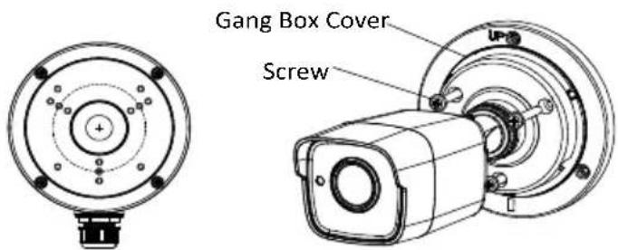
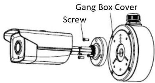
- Take apart the gang box and align the screw holes of the bullet camera and the gang box cover.
- Route the cables through the cable hole of gang box and x the camera with the gang box cover with the supplied screws, as shown in Figure 2-4.
text_image
Gang Box Cover ScrewFigure 2-4 Fix the Camera with the Gang Box
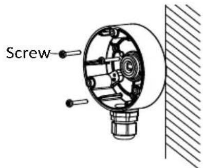
- Drill the screw holes in the ceiling/wall according to the supplied drill template.
- Hammer the supplied screws into the screw holes to x the gang box to the ceiling/wall.
text_image
ScrewFigure 2-5 Fix the Camera to the Ceiling
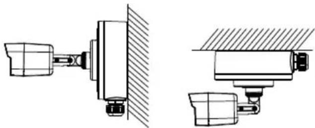
- Connect the corresponding cables and install the gang box cover with xing screws.
natural_image
Technical line drawings of mechanical components, including a valve and housing assembly (no text or symbols)Figure 2-6 Fix the Camera to the Ceiling/Wall
- Refer to step 5 of 2.1.1 to adjust the camera to get an opmum angle.
2.2 Installaon of Type II Camera
2.2.1 Ceiling/Wall Mounng without Gang Box
Steps:
- Aach the drill template (supplied) to the place where you want to x the camera, and then drill the screw holes and the cable hole in the ceiling/wall according to the drill template.
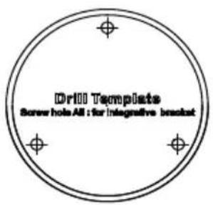
text_image
Drill Template Screwhole All its integrative bracketFigure 2-7 Drill Template
- Route the cables through the cable hole.
- Secure the camera to the ceiling with the supplied Screws.
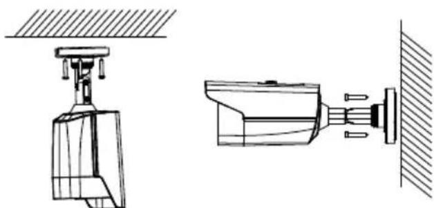
natural_image
Technical line drawing of a mechanical device with two views: top shows a mounted component, bottom shows a connected bracket (no text or symbols)Figure 2-8 Fix the Camera to the Ceiling/Wall
- Connect the corresponding cables.
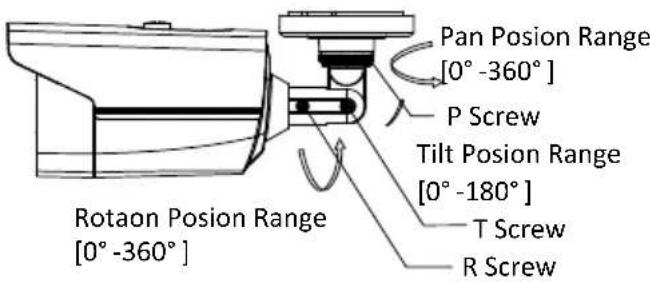
- Adjust the camera according to Figure 2-9 to get an opmum angle.
1). Loosen the P screw to adjust the pan direcon [0°\~360°]. Tighten the screw aer compleng the adjustment.
2). Loosen the T screw to adjust the lt direcon [0^ 180^] . Tighten the screw aer compleng the adjustment.
3). Loosen the R screw and rotate the camera [0^ 360^] to adjust the lens to the surveillance angle. Tighten the screw aer compleng the adjustment.
text_image
Pan Posion Range [0° -360°] P Screw Tilt Posion Range [0° -180°] T Screw R Screw Rotaon Posion Range [0° -360°]Figure 2-9 3-axis Adjustment
2.2.2 Ceiling/Wall Mounng with Gang Box

You need to purchase a gang box separately if you adopt ceiling mounng.
Steps:
- Take apart the gang box and align the screw holes of the bullet camera and the gang box cover.
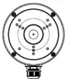
natural_image
Technical line drawing of a circular mechanical component with concentric rings and mounting holes (no text or symbols)Figure 2-10 Gang Box
- Route the cables through the cable hole of gang box and x the camera with the gang box cover with the supplied screws, as shown in Figure 2-11.
text_image
Gang Box Cover ScrewFigure 2-11 Fix the Camera with the Gang Box
- Drill the screw holes in the ceiling/wall according to the supplied drill template.
- Hammer the supplied screws into the screw holes to x the gang box to the ceiling/wall.
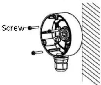
text_image
ScrewFigure 2-12 Fix the Camera to the Ceiling
- Connect the corresponding cables and install the gang box cover with xing screws.
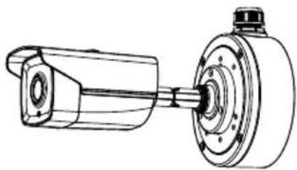
natural_image
Technical line drawing of a mechanical assembly with a shaft and housing (no text or symbols)Figure 2-13 Fix the Camera to the Ceiling/Wall
- Refer to step 5 of 2.2.1 to adjust the camera to get an opmum angle.
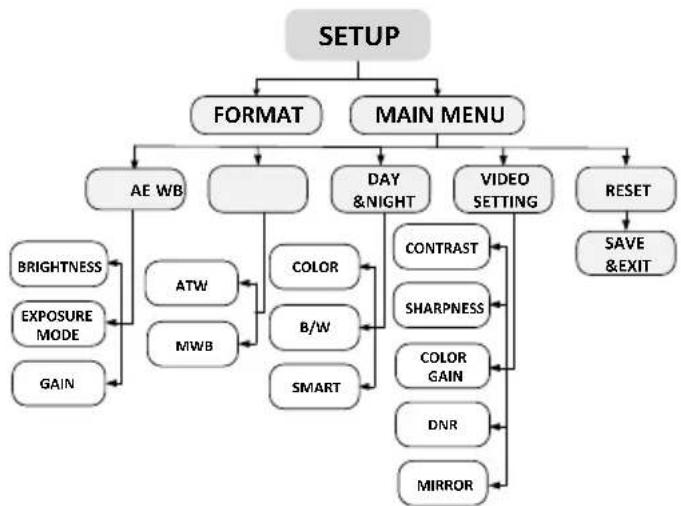
3 Menu Descripon
flowchart
graph TD
    A["SETUP"] --> B["FORMAT"]
    A --> C["MAIN MENU"]
    B --> D["AE WB"]
    B --> E["DAY & NIGHT"]
    B --> F["VIDEO SETTING"]
    C --> G["RESET"]
    D --> H["BRIGHTNESS"]
    D --> I["EXPOSURE MODE"]
    D --> J["GAIN"]
    E --> K["ATW"]
    E --> L["MWB"]
    E --> M["COLOR"]
    E --> N["B/W"]
    E --> O["SMART"]
    F --> P["CONTRAST"]
    F --> Q["SHARPNESS"]
    F --> R["COLOR GAIN"]
    F --> S["DNR"]
    F --> T["MIRROR"]
    P --> U["SAVE & EXIT"]
Figure 3-1 Main Menu Overview

- With a camera controller (purchased separately) or calling the preset No. 95 of DVR you can select the menu and adjust the parameters.
- Move the cursor up/down to select the menu item.
- Move the cursor le/right to adjust the value of the selected item.
- Press the OK key to conrm a selecon.
3.1 Format
Move the cursor to FORMAT, and press the menu buon to enter the FORMAT sub menu. You can set the format of camera and conrm.
3.2 Main Menu
3.2.2 AE (Auto Exposure)
AE describes the brightness-related parameters. You can adjust the image brightness by the BRIGHTNESS, EXPOSURE MODE, and GAIN in different light conditions.
EXPOSURE
| BRIGHTNESS | 5 |
| EXPOSURE MODE | BLC |
| LV | 5 |
| GAIN | MIDDLE |
| RETURN |
Figure 3-2 AE
BRIGHTNESS
Brightness refers to the brightness of the image. You can set the brightness value from 1 to 10 to darken or brighten the image. The higher the value is, the brighter the image is.
EXPOSURE MODE
You can set AE mode as GLOBAL, BLC, and WDR.
GLOBAL
GLOBAL refers to the normal exposure mode which is for adjusting the situations including unusual lightng distribution, variations, non-standard processing, or other conditions of under exposure to get an opmum image.
● BLC (Backlight Compensaon)
BLC (Backlight Compensaon) compensate light to the object in the front to make it clear, but this causes the over-exposure of the background where the light is strong.
When BLC is selected as the exposure mode, the BLC level can be adjusted from 0 to 8.
● WDR (Wide Dynamic Range)
The wide dynamic range (WDR) funcon helps the camera provide clear images even under back light circumstances. WDR balances the brightness level of the whole image and provide clear images with details.
GAIN
It optimizes the clarity of image in poor light scene. The GAIN level can be set to HIGH, MIDDLE, and LOW. Select OFF to disable the GAIN funcon.
The noise will be amplified if the GAIN is on.
3.2.3 WB (White Balance)
White balance is the white rendition funcon of the camera to adjust the color temperature according to the environment. It can remove the unrealisc color casts in the image. You can set WB mode as ATW, and MWB.
ATW
In ATW mode, white balance is being adjusted automatically according to the color temperature of the scene illuminaon.
MWB
You can set the R GAIN/B GAIN value from 0 to 255 to adjust the shades of red/blue color of the image.
WB
| MODE | MWB |
| R GAIN | 5 |
| B GAIN | 5 |
RETURN
Figure 3-3 MWB Mode
3.2.4 DAY-NIGHT
Color, B/W, and SMART are selectable for DAY and NIGHT switches.
COLOR
The image is colored in day mode all the me.
B/W
The image is black and white all the me, and the IR LED turns on in the low-light conditions.
SMART
You can select to turn on/o the INFRARED and set the value of SMART IR in this menu.
DAY/NIGHT
| MODE | SMART |
| INFRARED | OPEN |
| SMART IR | 1 |
RETURN
Figure 3-4 Day & Night
INFRARED
You can select to turn on/o the IR LED to response to the requirements of dierent circumstances.
SMART IR
The Smart IR funcon is used to adjust the light to its most suitable intensity, and to prevent the image from over exposure. The SMART IR value can be adjusted from 0 to 3. The higher the value is, the more obvious eects are, and it is disabled when the value is 0.
3.2.5 VIDEO SETTING
Move the cursor to VIDEO SETTING and press the conrm buon to enter the submenu. CONTRAST, SHARPNESS, COLOR GAIN, DNR and MIRROR are adjustable.
VIDEO SETTING
| CONTRAST | 5 |
| SHARPNESS | 5 |
| COLOR GAIN | 5 |
| DNR | 5 |
| MIRROR | DEFAULT |
RETURN
Figure 3-5 Video Seng
CONTRAST
This feature enhances the dience in color and light between parts of an image. You can set the CONTRAST value from 1 to 10.
SHARPNESS
Sharpness determines the amount of detail an imaging system can reproduce. You can set the SHARPNESS value from 1 to 10.
COLOR GAIN
Adjust this feature to change the saturaton of the color. The value ranges from 1 to 10.
DNR (Digital Noise Reducon)
The DNR funcon can decrease the noise effect, especially when capturing moving images in low light conditions and delivering more accurate and sharp image quality.
You can set the DNR value from 1 to 10.
MIRROR
DEFAULT, H, V, and HV are selectable for mirror.
DEFAULT: The mirror funcon is disabled.
H: The image ips 180 degree horizontally.
V: The image ips 180 degree vercally.
HV: The image ips 180 degrees both horizontally and vercally.
3.2.6 RESET
Reset all the sengs to the default.
3.2.7 SAVE &EXIT
Move the cursor to SAVE &EXIT and press OK to save the seng and exit the menu.
4 IR Reecon Prevenon

For the camera that supports IR, you are required to pay aenon to the following precautions to prevent IR reecon:
- Dust or grease on the dome cover will cause IR reecon. Please do not remove the dome cover lm unl the installaon is nished. If there is dust or grease on the dome cover, clean the dome cover with clean so cloth and isopropyl alcohol.
● Make sure that there is no reecve surface too close to the camera lens. The IR light from the camera may react back into the lens causing reecon. - The foam ring around the lens must be seated ush against the inner surface of the bubble to isolate the lens from the IR LEDs. Fasten the dome cover to camera body so that the foam ring and the dome cover are aached seamlessly.