AR421-CKT001 - Voice recorder Kguard - Free user manual and instructions
Find the device manual for free AR421-CKT001 Kguard in PDF.

| Product Type | Voice Recorder |
| Brand | Kguard |
| Model | AR421-CKT001 |
| Dimensions (approx.) | 10 cm x 3 cm x 1 cm |
| Weight (approx.) | 30 g |
| Power Source | Built-in rechargeable battery via USB |
| Recording Format | MP3 / WAV (typical) |
| Storage Capacity | Internal memory (size unspecified, likely 4GB-16GB) |
| Playback | Built-in speaker and headphone jack |
| Connectivity | USB 2.0 for file transfer and charging |
| Battery Life | Up to 10 hours recording (estimated) |
| Charging Time | Approx. 2 hours |
| Maintenance | Keep dry; clean with soft dry cloth |
| Safety Warnings | Do not expose to water; do not disassemble |
| Spare Parts & Repairability | Not user-serviceable; contact support for issues |
| General Information | Includes 81-page user manual in English |
Frequently Asked Questions - AR421-CKT001 Kguard
User questions about AR421-CKT001 Kguard
0 question about this device. Answer the ones you know or ask your own.
Ask a new question about this device
Download the instructions for your Voice recorder in PDF format for free! Find your manual AR421-CKT001 - Kguard and take your electronic device back in hand. On this page are published all the documents necessary for the use of your device. AR421-CKT001 by Kguard.
USER MANUAL AR421-CKT001 Kguard
DVR with Cloud Technology Aurora Series
Default user name: admin
Default password: 123456
About this Manual
The material in this document is for information purpose and is subject to change without prior notice. We made every effort to ensure that this user's manual is accurate and complete. However, no liability is assumed for any errors and omissions that may have occurred.
FCC Compliance Statement
This equipment has been tested and found to comply with the limits for a Class B digital device, pursuant to Part 15 of the FCC Rules. These limits are designed to provide reasonable protection against harmful interference in a residential installation. This equipment generates uses and can radiate radio frequency energy and, if not installed and used in accordance with the instructions, may cause harmful interference to radio communications. However, there is no guarantee that interference will not occur in a particular installation. If this equipment does cause harmful interference to radio or television reception, which can be determined by turning the equipment off and on, the user is encouraged to try to correct the interference by one or more of the following measures:
- Reorient or relocate the receiving antenna.
- Increase the separation between the product and receiver.
- Connect the product into an outlet on a circuit different from that to which the receiver is connected.
- Consult the dealer or an experienced radio/TV technician for help.
Declaration of Conformity
This device complies with part 15 of the FCC Rules. Operation is subject to the following two conditions:
- This device may not cause harmful interference.
- This device must accept any interference received, including interference that may cause undesired operation.
Copyright
Limitation of Liability
- This publication is provided "AS IS" without warranty of any kind, either expressed or implied, including but not limited to, the implied warranties of merchantability, fitness for any particular purpose, or non-infringement of a third party's rights.
- This publication may include technical inaccuracies or typographical errors. Changes may be made to the information herein, at any time, for publication improvements and/or of the corresponding device(s).
Disclaimer of Warranty
In no event shall the supplier be liable to any party or any person, except for replacement or reasonable maintenance of the product, for the cases, including but not limited to the following:
- Any damage or loss, including but without limitation, direct or indirect, special, consequential or exemplary, arising out of or relating to the device;
- Personal injury or any damage caused by inappropriate use or negligent operation of the user;
- Unauthorized disassemble, repeat or modification of the device by the user;
- Any problem, consequential inconvenience, or loss or damage, arising out of combining the system with the devices of a third party;
- Any claim or action for damages, brought by any person or organization being a photogenic subject, due to violation of privacy with the result of pictures from a surveillance camera, including saved data, for some reason, becomes public or is used for the purpose other than for surveillance.
Safety Information

Warning
This is the symbol for indicating any potential hazard, risk or condition requiring special attention. The user needs to refer to the important operating and maintenance or servicing instructions.

Caution
The lighting flash with an arrow head symbol, in an equilateral triangle, is intended to alert the user. There is dangerous "voltage" presence near by the product's enclosure which may be risk of person.
Safety Precautions
- Do not touch live electrical parts.
Electric shock can be avoided. Follow the recommended practices listed below. Faulty installation, improper grounding, and incorrect operation and maintenance of electrical equipment are always sources of danger. - Do not try to install equipment outdoor, during strong wind and rain.
- Do not install or remove equipment outdoor, when raining.
- Do not try to install or operate any equipment, during a thunderstorm.
• Always ground all electrical equipment and the work platform.
Prevent accidental electrical shocks. Connect power source, control cabinets, and work platform to an approved electrical ground.
• Always use the correct cable size.
Sustained overloading will cause cable failure and result in possible electrical shock or fire hazard. Work cable should be the same rating as the factory.
• Always keep cables and connectors in good condition.
Improper or worn electrical connections can cause short circuits and can increase the chance of an electrical shock. Do not use worn, damaged, or bare cables.
• Always avoid open-circuit voltage.
The added voltages increase the severity of electric shock hazard. - Always wear insulated gloves while you adjust equipment.
Electric power should be turned off and insulated gloves should be worn when making any equipment adjustment to assure shock protection. - Always wear protective clothing such as long sleeve shirts while you are installing or removing equipment.
• Always wear high, snug fitting shoes.
• Always wear clean clothes without grease or oil.
- Protect neighboring workers from exposure to arc radiation.
• Always wear long trousers or jeans while you are installing or removing equipment.
• Always wear safety helmet or hard head and safety shoes before work.
• Always keep the equipment in dry places.
- Always wear safety harnesses/belt while you work in high places.
• Always wear dry clothing and avoid moisture and water.
• Always wear Public Safety Vest, while you work at night.
- Make sure all electrical connections are tight, clean, and dry.
- Make sure that you are well insulated to eliminate electric static charge.
- Always wear dry gloves, rubber-soled shoes, or stand on a dry board or platform.
• Always follow recognized safety standards.
• Always wear correct eye, ear, and body protection.
• Always have second person on-site, while you work in dark, poor ventilation, or high places.
- Make sure that you are well protected against arc flashes, mechanical injury, or other mishaps.
- Make sure that the polarity of wire is correct before installing equipment.
• Always handle equipment with care.
- Do not block the ventilation of equipment.
- Do not put the magnetic parts around the equipment.
- Do not put the objects on top of the equipment.
Contents
About this Manual 2
FCC Compliance Statement.... 2
Copyright 2
Safety Information 3
Introduction 7
Product Overview 7
Front Panel 7
Rear Panel 7
4-Channel DVR 7
8-Channel DVR 7
16-Channel DVR 8
Remote Control....9
Mouse....10
Getting Started 11
Installing the Hard Disk Drive.... 11
Making Connection.... 13
Basic Connection.... 13
4-Channel / 8-Channel DVR 13
16-Channel DVR.... 14
Connecting to Other Devices.... 15
4-Channel / 8-Channel DVR 15
16-Channel DVR.... 16
Easy Network Setup.... 17
Basic Connection for Remote Live View on Smart Phone/Pad 17
Basic Connection for Remote Live View on MyKguard.... 17
Basic Connection for Uploading Images to Cloud 19
Setup Wizard.... 21
Enter Administrator Password.... 21
Basic Setup 22
Network Setup & Testing.... 22
DDNS & Port Setup.... 23
HDD Setup 24
Completing the Setup Wizard 24
Operating the DVR.... 25
Logging in.... 25
Main Screen 25
Task Bar 26
Configuring DVR Settings 31
Main Menu 31
Basic Menu 33
System Setup.... 33
Date/Time Setup 33
Date/Time 33
DST (Daylight Saving Time).... 34
Display Setup.... 34
Display.... 34
Margin....36
Auto Sequence 36
Main Output 37
Record Setup 38
Basic 38
Bit rate 38
Schedule.... 39
User Setup 40
Advance Menu 42
Alarm Setup 42
Motion 42
Sensor 45
Video Loss 47
Others 48
LAN 49
PPPoE 50
Port 50
Sub-stream....51
Communication Setup.... 51
MyKguard....51
DDNS 52
E-mail 52
UPnP 53
Cloud 54
PTZ Setup....55
Search 55
Record Search....55
Backing up Videos....56
Playing Videos....57
Trimming Videos 58
Log Search 59
Disk Management....60
HDD 60
Formatting HDD 60
USB Storage 60
Formatting USB Disk Drive 60
Managing USB Disk Drive 61
eSATA (16-channel DVR only) 61
Information....62
Device....62
Network....62
Online 62
Record 63
Maintenance....63
Basic 63
Manual Reboot 64
Set Auto Maintenance 64
Update System Firmware....65
Contents
Settings....65
Load Default Settings 66
Logout....66
Web Client....67
PC login 67
Interface Overview 68
Switching Screen Modes 69
Video Playback....70
Searching and Playing Videos....70
Downloading Recorded Videos 71
Configure Settings....72
Information 72
Date/Time 73
Record 74
User 74
Alarm....75
Network....75
COMM 76
System Manage 76
Local Settings....77
Log....77
Appendix....78
Troubleshooting....78
Specifications....79
Introduction
Product Overview
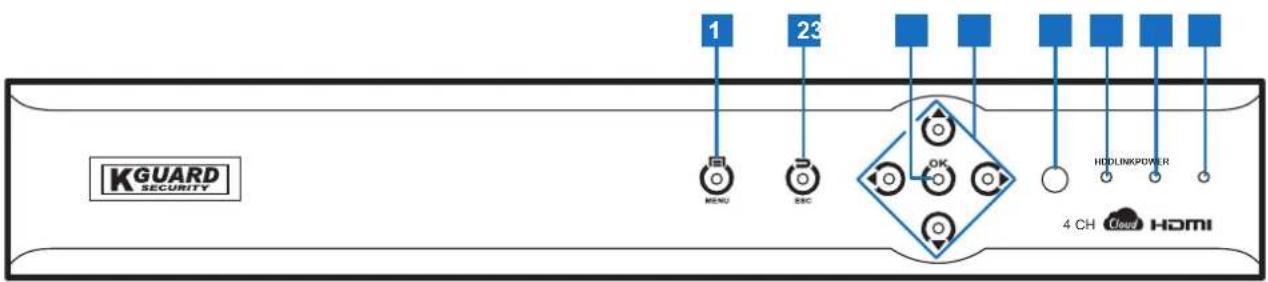
Front Panel
flowchart
graph LR
    A["KGUARD SECURITY"] --> B["1"]
    A --> C["23"]
    A --> D["OK"]
    A --> E["4 CH Cloud HDMI"]
    B --> F["RENU"]
    C --> G["ZEC"]
    D --> H["HDLINKPOWER"]
    E --> I["Cloud"]
1) Menu: Press to enter the menu.
2) Esc: Press to exit the current menu.
3) OK: Press to enter the selected menu item and confirm the setting.
4) Direction keys: Press to navigate the menus.
5) IR receiver: Receives incoming remote control commands.
6) HDD LED: Lights blue when the HDD is being accessed.
7) Link LED: Lights green to indicate a valid network link is established on the LAN port.
8) Power LED: Lights red to indicate the power is turned on.
Rear Panel
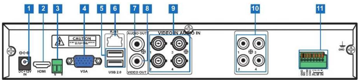
4-Channel DVR
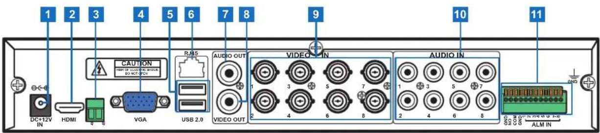
8-Channel DVR
16-Channel DVR
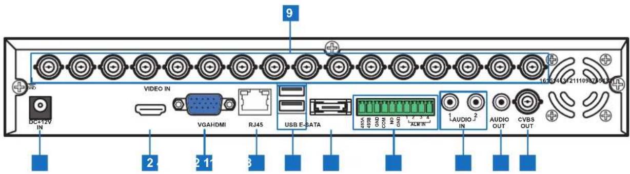
1) Power Input: Connects to the power adapter. Use only the supplied power adapter.
2) HDMI Output: Connects to a monitor via HDMI. For best video quality, it is recommended to use this connection.
For best possible displayed image, use a television or monitor which can display 1920x 1080 or higher.
3) RS485 (4/8-channel only): Connects to a Speed dome camera via RS-485.
4) VGA Output: Connects to a VGA monitor.
5) USB 2.0: Connects to a USB mouse or flash disk.
6) LAN: Connects to a network via RJ-45.
7) Audio Output: Connects to a speaker via RCA.

Note:
8) Video Output: Connects to a monitor or television via BNC.
9) Video Input: Connects to a maximum of 4 (4-channel DVR), 8 (8-channel DVR), or 16 (16-channel DVR) CCTV cameras (BNC).

Note:
The label shown on the port is the same channel number as it appears on the DVR interface.
10) Audio Input: Connects to a maximum of 4 (4-channel DVR), 8 (8-channel DVR), or 2 (16-channel DVR) microphones via RCA.
11) RS485 (16-channel only): Connects to a Speed dome camera, sensor or alarm device via RS-485.
12) eSATA: Connects to an external hard drive.
Remote Control
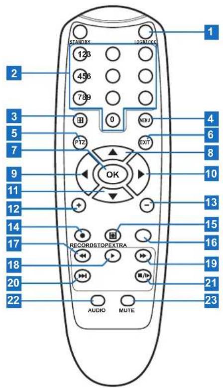
1) Login/Lock: Press to login/lock the main menu.
2) Numeric keys (1\~0): Press to display channel 1\~16.
3) Display mode: Press to switch to different display mode.
4) Menu: Press to enter the menu.
5) PTZ: Press to configure PTZ settings.
6) Exit: Press to exit the menu.
7) OK: Press to enter the selected menu item and confirm the setting.
8) Up: Press to move up in the OSD menu.
9) Left: Press to move left in the OSD menu.
10) Right: Press to move right in the OSD menu.
11) Down: Press to move down in the OSD menu.
12) +: Press to increase the volume level.
13) -: Press to decrease the volume level.
14) Record: Press to start manual recording.
15) Stop: Press to stop manual recording.
16) Extra: Reserved key.
17) Rewind: Press to rewind during video playback.
18) Play: Press to play recorded video.
19) Fast forward: Press to fast forward during video playback.
20) Slow play: Press to playback video at reduced speed.
21) Pause: Press to pause the video playback.
22) Audio: In Playback mode, press to turn the audio on.
23) Mute: Press to mute audio.
Mouse
The DVR is supplied with a USB mouse that you can use to operate the DVR. Simply plug in the supplied mouse into the USB mouse connector at the rear panel of the device.
| Mouse Operation Description | |
| Left-click In OSD menu, click the left button to select and edit the setting. | |
| Right-click In preview mode, click the right button to display the pop-up menu. | |
| Double-click the Left button Double-click the live image of any channel for full screen display. Double-click the left button again to return to the window-display of all cameras. | |
| Drag an area/line In motion mode, use this function to select motion area. | |
Getting Started
Installing the Hard Disk Drive
Depending on the package you have purchased, the hard disk drive may be included in the full package. If it is not pre-installed, follow the installation instructions on this user manual.

DO NOT install or remove the hard disk drive while the device power is turned on.
The DVR supports one 3.5" SATA hard disk drive. To install the HDD, follow the steps below.

Note:
The illustrations below show an 8-channel DVR, same procedures apply to a 4/16-channel DVR.
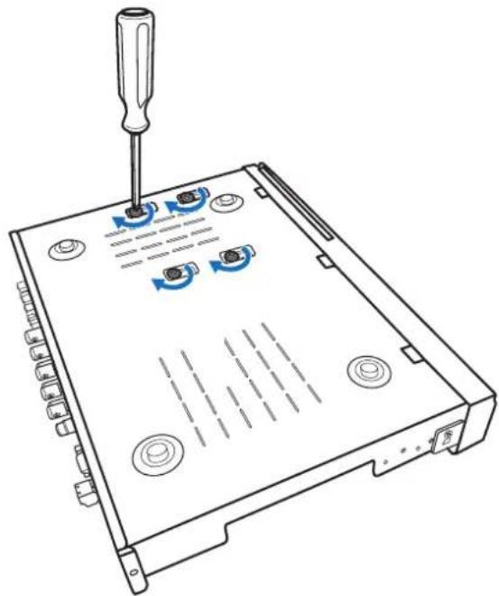
Step 1: Remove the cover
a. Loosen the screws in the left, right, and rear sides as shown.
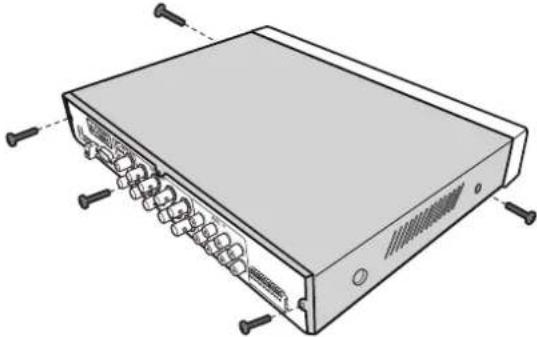
natural_image
Illustration of a computer rack with multiple ports and screw connectors (no text or symbols)b. Push back then lift up the cover to remove it.
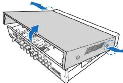
natural_image
Diagram of a server rack with internal components and blue directional arrows indicating motion (no text or symbols)Step 2: Install HDD
Connect the data and power cables to the hard disk drive (HDD) and place the HDD on the DVR case.
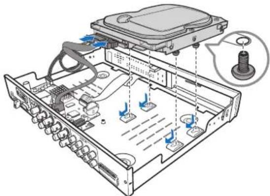
natural_image
Diagram of an internal electronic device showing ports, cables, and a screw (no text or labels present)Step 3: Secure HDD
Align the HDD to the holes on the DVR case and secure the HDD using the four (4) supplied screws.
natural_image
Line drawing of a computer drive chassis with screwdriver and multiple ports (no text or symbols)Step 4: Replace the cover
Attach the cover and the screws back in place.
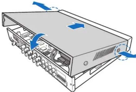
natural_image
Diagram of a server rack with internal components and blue directional arrows indicating movement (no text or symbols)Making Connection
Basic Connection
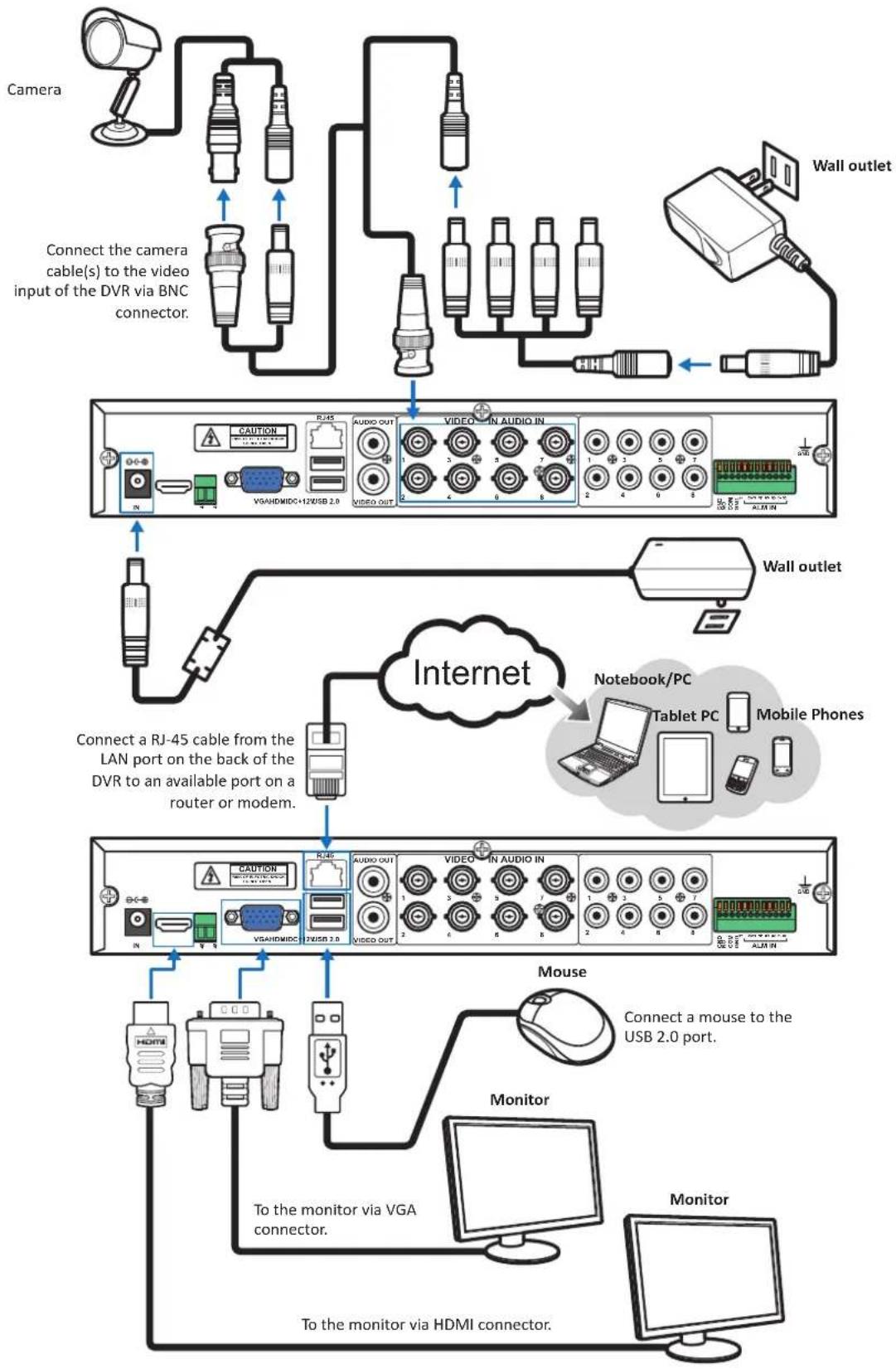
4-Channel / 8-Channel DVR
flowchart
graph TD
    A["Camera"] --> B["Connect the camera cable(s) to the video input of the DVR via BNC connector."]
    B --> C["Wall outlet"]
    C --> D["Video/IN AUDIO IN"]
    D --> E["Video/IN Audio IN"]
    E --> F["Mobile Phones"]
    F --> G["Internet"]
    G --> H[" notebook/PC"]
    H --> I["Tablet PC"]
    I --> J["Monitor"]
    J --> K["To monitor via VGA connector."]
    K --> L["Monitor via HDMI connector."]
    L --> M["To monitor via HDMI connector."]
    M --> N["Computer"]
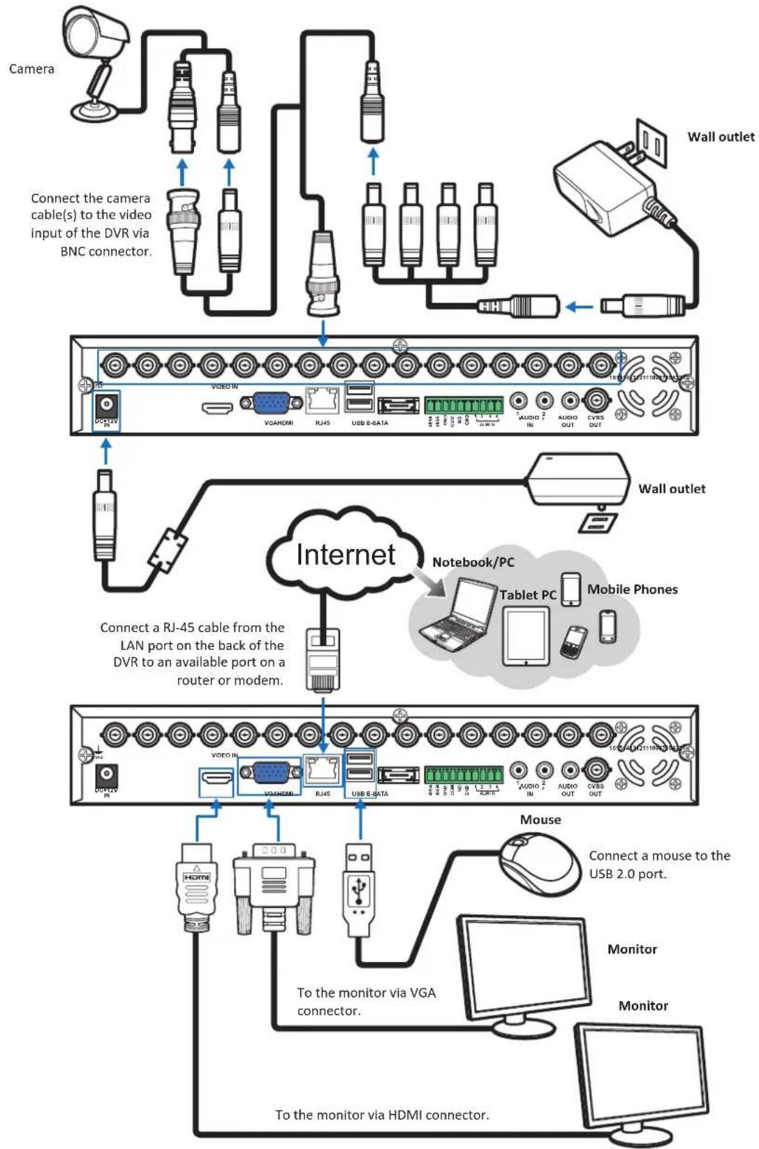
16-Channel DVR
flowchart
graph TD
    A["Camera"] --> B["Connect the camera cable(s) to the video input of the DVR via BNC connector."]
    B --> C["Wall outlet"]
    C --> D["Video IN"]
    D --> E["VR/HDMI"]
    E --> F["RJ45"]
    F --> G["USB E-SATA"]
    G --> H["1 AUDIO 2 IN"]
    H --> I["AUDIO OUT"]
    I --> J["CVBS OUT"]
    J --> K["Mobile Phones"]
    K --> L[" notebook/PC"]
    L --> M["Tablet PC"]
    M --> N["Mobile Phone"]
    N --> O["Internet"]
    O --> P["Connect a RJ-45 cable from the LAN port on the back of the DVR to an available port on a router or modem."]
    P --> Q["Mobile Phone"]
    Q --> R["Mouse"]
    R --> S["Connect a mouse to the USB 2.0 port."]
    S --> T["Monitor"]
    T --> U["Monitor"]
    U --> V["To the monitor via VGA connector."]
    V --> W["To the monitor via HDMI connector."]
Connecting to Other Devices
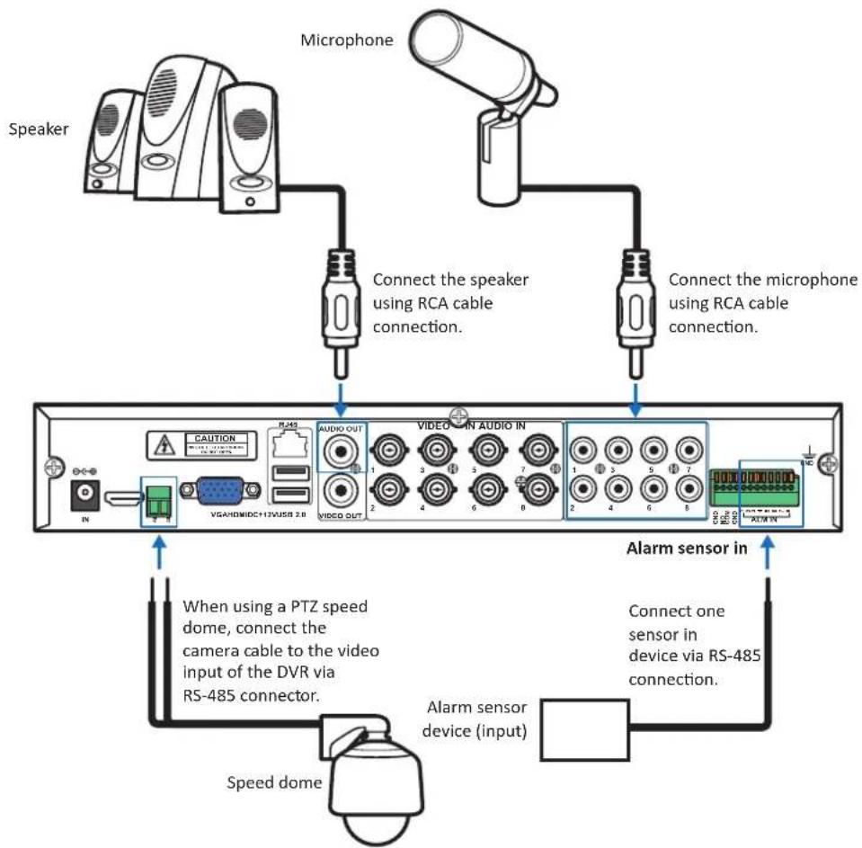
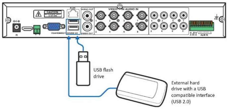
4-Channel / 8-Channel DVR
flowchart
graph TD
    A["Speaker"] --> B["Connect the speaker using RCA cable connection."]
    C["Microphone"] --> B
    D["Speaker"] --> E["Connect the microphone using RCA cable connection."]
    F["Speaker"] --> G["Connect the speaker using RCA cable connection."]
    H["Speaker"] --> I["Connect the microphone using RCA cable connection."]
    J["Speaker"] --> K["Connect the microphone using RCA cable connection."]
    L["Speaker"] --> M["Connect the microphone using RCA cable connection."]
    N["Speaker"] --> O["Connect the microphone using RCA cable connection."]
    P["Speaker"] --> Q["Connect the microphone using RCA cable connection."]
    R["Speaker"] --> S["Connect the microphone using RCA cable connection."]
    T["Speaker"] --> U["Connect the microphone using RCA cable connection."]
    V["Speaker"] --> W["Connect the microphone using RCA cable connection."]
    X["Speaker"] --> Y["Connect the microphone using RCA cable connection."]
    Z["Speaker"] --> AA["Connect the microphone using RCA cable connection."]
    AB["Speaker"] --> AC["Connect the microphone using RCA cable connection."]
    AD["Speaker"] --> AE["Connect the microphone using RCA cable connection."]
    AF["Speaker"] --> AG["Connect the microphone using RCA cable connection."]
    AH["Speaker"] --> AI["Connect the microphone using RCA cable connection."]
    AJ["Speaker"] --> AK["Connect the microphone using RCA cable connection."]
    AL["Speaker"] --> AM["Connect the microphone using RCA cable connection."]
    AN["Speaker"] --> AO["Connect the microphone using RCA cable connection."]
    AP["Speaker"] --> AQ["Connect the microphone using RCA cable connection."]
    AR["Speaker"] --> AS["Connect the microphone using RCA cable connection."]
    AT["Speaker"] --> AU["Connect the microphone using RCA cable connection."]
    AV["Speaker"] --> AW["Connect the microphone using RCA cable connection."]
    AX["Speaker"] --> AY["Connect the microphone using RCA cable connection."]
    AZ["Speaker"] --> BA["Connect the microphone using RCA cable connection."]
    BB["Speaker"] --> BC["Connect the microphone using RCA cable connection."]
    BD["Speaker"] --> BE["Connect the microphone using RCA cable connection."]
    BF["Speaker"] --> BG["Connect the microphone using RCA cable connection."]
    BH["Speaker"] --> BI["Connect the microphone using RCA cable connection."]
    BJ["Speaker"] --> BK["Connect the microphone using RCA cable connection."]
    BL["Speaker"] --> BM["Connect the microphone using RCA cable connection."]
    BN["Speaker"] --> BO["Connect the microphone using RCA cable connection."]
    BP["Speaker"] --> BQ["Connect the microphone using RCA cable connection."]
    BR["Speaker"] --> BS["Connect the microphone using RCA cable connection."]
    BT["Speaker"] --> BU["Connect the microphone using RCA cable connection."]
    BV["Speaker"] --> BW["Connect the microphone using RCA cable connection."]
    BX["Speaker"] --> BY["Connect the microphone using RCA cable connection."]
    BZ["Speaker"] --> CA["Connect the microphone using RCA cable connection."]
    CB["Speaker"] --> CC["Connect the microphone using RCA cable connection."]
    CD["Speaker"] --> CE["Connect the microphone using RCA cable connection."]
    CF["Speaker"] --> CG["Connect the microphone using RCA cable connection."]
    CH["Speaker"] --> CI["Connect the microphone using RCA cable connection."]
    CJ["Speaker"] --> CK["Connect the microphone using RCA cable connection."]
    CL["Speaker"] --> CM["Connect the microphone using RCA cable connection."]
    CN["Speaker"] --> CO["Connect the microphone using RCA cable connection."]
    CP["Speaker"] --> CBU["Connect the microphone using RCA cable connection."]
    CRI["Speaker"] --> CS["Connect the microphone using RCA cable connection."]
    CT["Speaker"] --> CU["Connect the microphone using RCA cable connection."]
    CV["Speaker"] --> CW["Connect the microphone using RCA cable connection."]
    CX["Speaker"] --> CY["Connect the microphone using RCA cable connection."]
    CZ["Speaker"] --> CEU["Connect the microphone using RCA cable connection."]
    DA["Speaker"] --> CEV["Connect the microphone using RCA cable connection."]
    DB["Speaker"] --> CEV1["Connect the microphone using RCA cable connection."]
    DC["Speaker"] --> CEV2["Connect the microphone using RCA cable connection."]
    DV["Speaker"] --> DV1["VGA/HDMI/CD+17/VI/SS 2.8"]
    DW["AUDIO OUT"] --> DX["VIBIO OUT"]
    DX --> DY1["V1: 3, 4, 5, 6, 7, 8, 9, 10, 11, 12, 13, 14, 15, 16, 17, 18, 19, 20, 21, 22, 23, 24, 25, 26, 27, 28, 29, 30, 31, 32, 33, 34, 35, 36, 37, 38, 39, 40, 41, 42, 43, 44, 45, 46, 47, 48, 49, 50, 51, 52, 53, 54, 55, 56, 57, 58, 59, 60, 61, 62, 63, 64, 65, 66, 67, 68, 69, 70, 71, 72, 73, 74, 75, 76, 77, 78, 79, 80, 81, 82, 83, 84, 85, 86, 87, 88, 89, 90, 91, 92, 93, 94, 95, 96, 97, 98, 99, 100"]
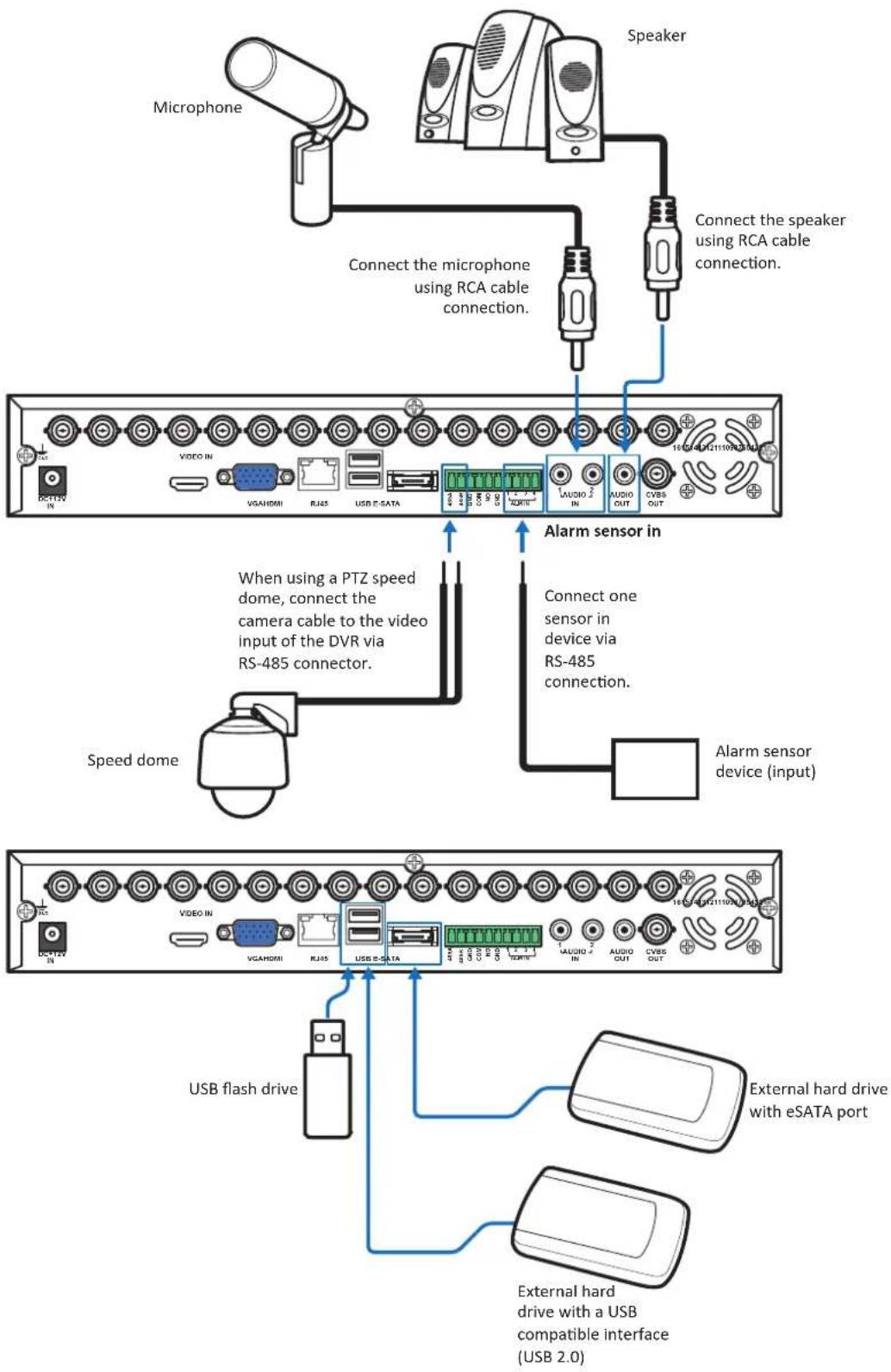
16-Channel DVR
flowchart
graph TD
    A["Microphone"] --> B["Connect the microphone using RCA cable connection."]
    B --> C["Speaker"]
    C --> D["Connect the speaker using RCA cable connection."]
    D --> E["Video IN"]
    E --> F["When using a PTZ speed dome, connect the camera cable to the video input of the DVR via RS-485 connector."]
    F --> G["Speed dome"]
    G --> H["Alarm sensor in device (input)"]
    H --> I["Connect one sensor in device via RS-485 connection."]
    I --> J["USB flash drive"]
    J --> K["External hard drive with eSATA port"]
    K --> L["External hard drive with a USB compatible interface (USB 2.0)"]
Easy Network Setup
The outstanding feature of this DVR is that you do not need to do any complicated network settings to set up the DVR for remote live view on smart phone/pad/web browsers (MyKguard) or uploading images to Cloud.
In a DHCP typical personal home LAN (Local Area Network), basic steps are as below:
Basic Connection for Remote Live View on Smart Phone/Pad
Step 1: Connect the DVR to network
a. Connect the power adapter to the DVR. See "Making Connection" on page 13.
b. Connect a RJ-45 cable from the LAN port on the back of the DVR to an available port on a router.
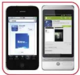
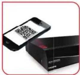
Step 2: Install APP
Download KViewQR application on your smart phone/pad.
Step 3: Add connected DVR and view Live screen
Add the connected DVR by scanning the QR code. Once the router provides IP address to DVR, the Live screen appears.
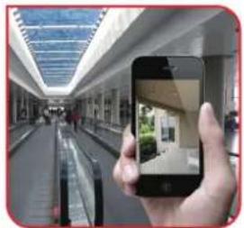
natural_image
Hand holding smartphone displaying a small photo of a building inside a modern corridor (no visible text or symbols)Basic Connection for Remote Live View on MyKguard
Step 1: Connect the DVR to network
a. Connect the power adapter to the DVR. See "Making Connection" on page 13.
b. Connect a RJ-45 cable from the LAN port on the back of the DVR to an available port on a router.
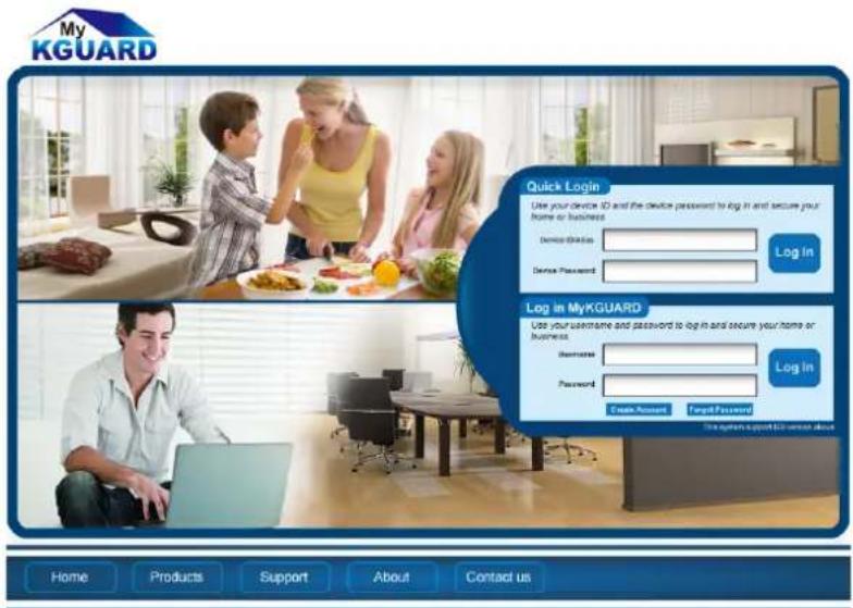
Step 2: Login to MyKguard
Open your computer IE browser (IE8 or above) and enter http://www.mykguard.com in the URL box. Enter the DVR ID and password on Quick Login. Then click Login.

Note:
DVR ID can be found at the following:
(1) On the DVR QR Code sticker.
(2) In DVR menu: Click > Information > Device > DVR ID.
SHOUQING(2013)WTOCOM 2013, A6.16. jhen. Pressen:
When using this function, make sure MyKguard is enabled prior accessing MyKguard.
In DVR menu: Click > Advance > COMM > MyKguard.
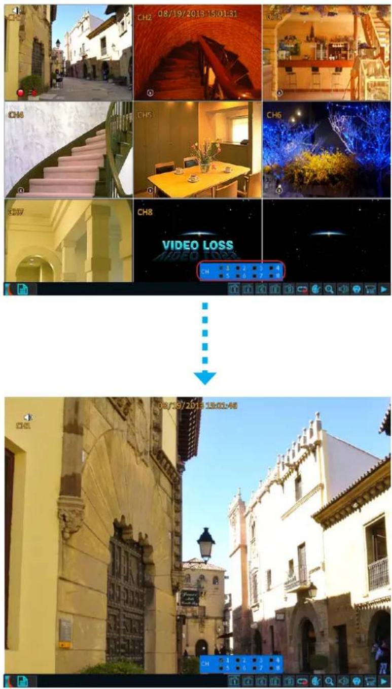
Step 3: View Live View
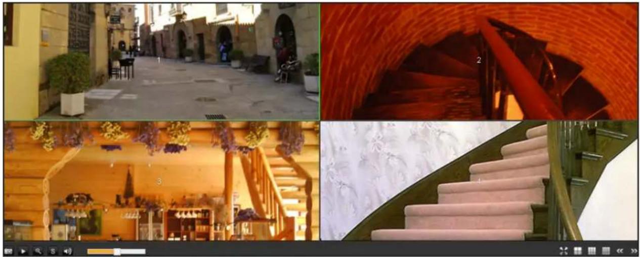
natural_image
Collage of four interior scenes: a stone-paved street, a red-tinted staircase with decorative elements, a wooden staircase with floral decorations, and a modern staircase with marble carvings (no visible text or symbols)Basic Connection for Uploading Images to Cloud
Step 1: Connect the DVR to network
a. Connect the power adapter to the DVR. See "Making Connection" on page 13.
b. Connect a RJ-45 cable from the LAN port on the back of the DVR to an available port on a router.
Step 2: Set Cloud Storage
In Main menu, select Advance > COMM > Cloud and type an email account to receive the cloud storage activation link. See "Cloud" on page 54.
Step 3: Activate Cloud Storage
There are two ways to activate cloud storage:
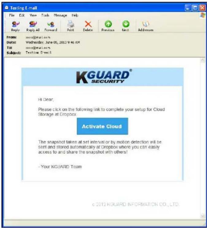
a. Via e-mail
An e-mail will be sent to the Receiver e-mail account after clicking ActiveCloud. You must check your e-mail and follow the link to complete cloud storage activation within 3 minutes.
Open your email and click Activate Cloud. Follow the on-screen instructions to complete the cloud account activation.
b. Via scanning QR code
A "QR code" also appears on the screen after clicking ActiveCloud.
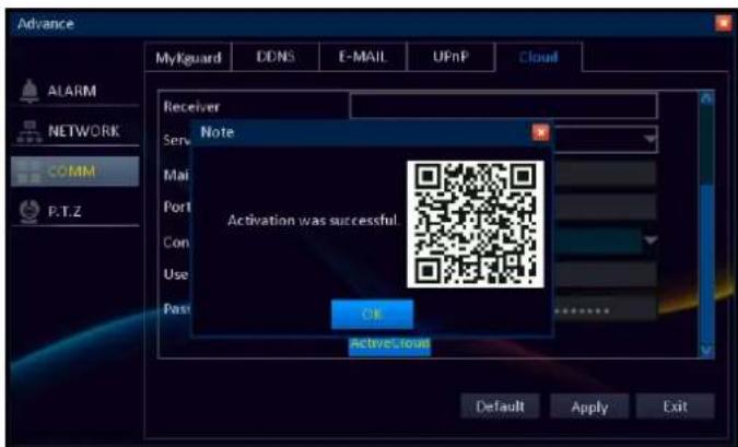
Using your smart phone/pad, simply scan the QR code and confirm the link to activate the Dropbox cloud storage.

Note:
Prior scanning the QR code with the smart phone/pad, you need to download the Kview QR application.
Step 4: View Snapshots
After the account activation is complete, the snapshot taken at the preset time interval or by motion detection will be uploaded and stored automatically at Dropbox.
Setup Wizard
The Setup Wizard will appear the first time you start the DVR. It will guide you to configure initial DVR settings including time setup, network setup, and other basic settings.

Follow the on-screen instructions to complete the initial setup.

Note:
To skip and disable Startup Wizard, check the "Don't display this window again" box and click Cancel.
Enter Administrator Password
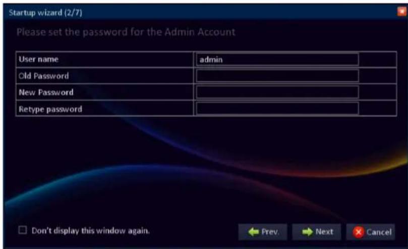
User name: By default, the administrator user name is set to "Admin".
Password: Old password (Default) is 123456. We suggest you change the password to protect your privacy.

Note:
If the password is left blank then the connection via portable device (smart phone/pad) to the DVR will not be established.
Basic Setup
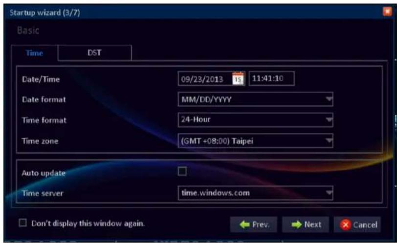
Click Time tab to configure the date and time settings. See "Date/Time" on page 33.
Click DST tab to configure the Daylight Saving Time settings. See "DST (Daylight Saving Time)" on page 34.
Network Setup & Testing
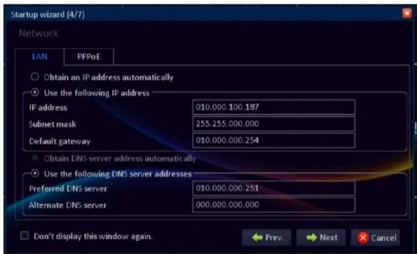
If you are using DHCP connection, select Obtain an IP address automatically.
If you are using Static IP connection, select Use the following IP address. Specify IP address, Subnet mask, and Gateway.

If you are using PPPoE connection, select PPPoE tab. Specify User name and Password.
See "LAN" on page 49 for further more information.
DDNS & Port Setup
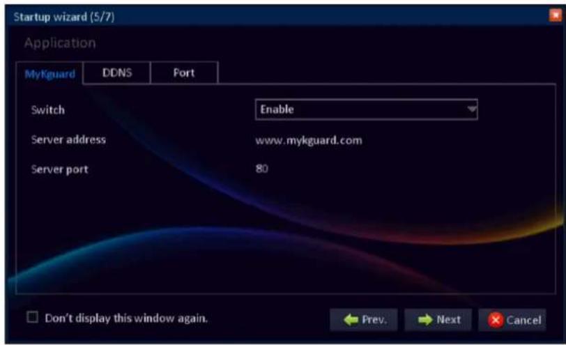
To enable remote live view the DVR via MyKguard, you need to enable the function first prior accessing MyKguard (http://www.mykguard.com).

Note:
For accessing MyKguard, it is advised to use Internet Explorer 8 or above.
Switch: Select Enable to enable this function.
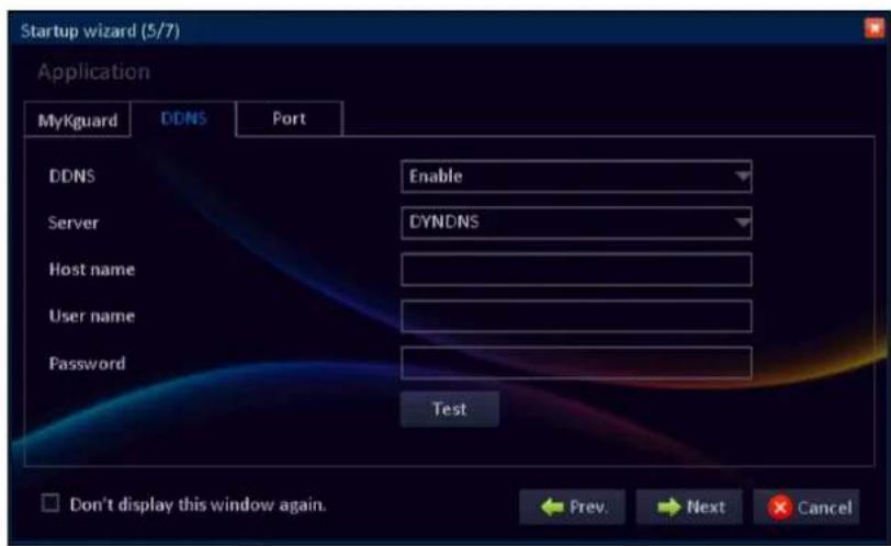
DDNS (Dynamic DNS) is a service that registers a domain name and the floating IP address with a DDNS server so that the domain name can be routed to the IP address even if the IP is changed in a dynamic IP system.
DDNS: Select Enable to enable this function.
Server: Select the DDNS server.
Host Name: Enter the domain name you registered on DDNS server.

Note:
If the registered domain name is 123ABC.KGUARD.ORG, the IP address you type on IE or Safari when you browse Web Client is http://123ABC.KGUARD.ORG.
User name: Enter the DDNS user name.
Password: Enter the DDNS password.
HDD Setup
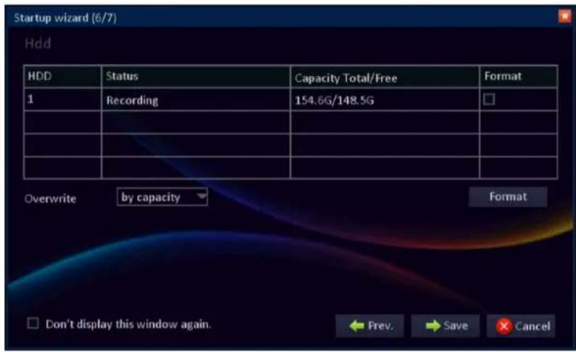
Display the HDD status and capacity. To format the HDD, check the Format box and click Format.
Overwrite: Select an overwrite interval options.
By days: Define the beginning date of the files that will be overwritten.
By capacity: Define the capacity limit when the oldest files will be overwritten.
Never: The recording will stop when the hard disk is full.
Completing the Setup Wizard
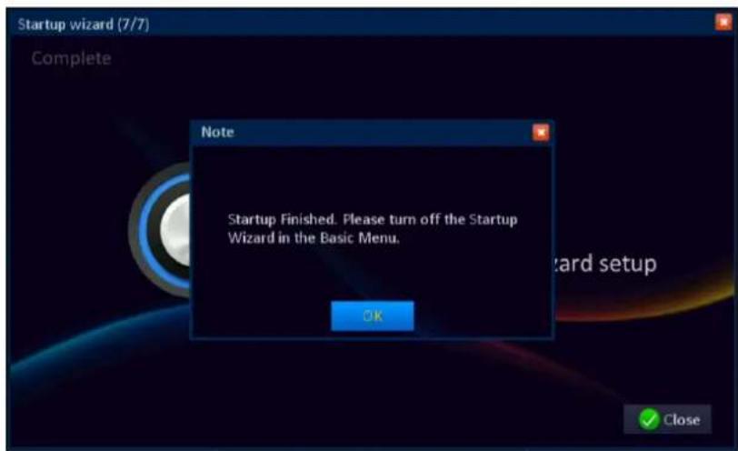
When you click Save, the system will automatically save all settings.
Click OK > Close to exit the Setup Wizard.
Note:
To prevent the Wizard Setup screen appears every time the system reboots, set the Startup wizard setting to Off in Basic menu. See "System Setup" on page 33.
Operating the DVR
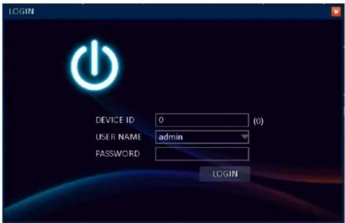
Logging in
Enter the user name and password before entering the Main menu.

Note:
The default user name and password are:
User name: admin
Password: 123456
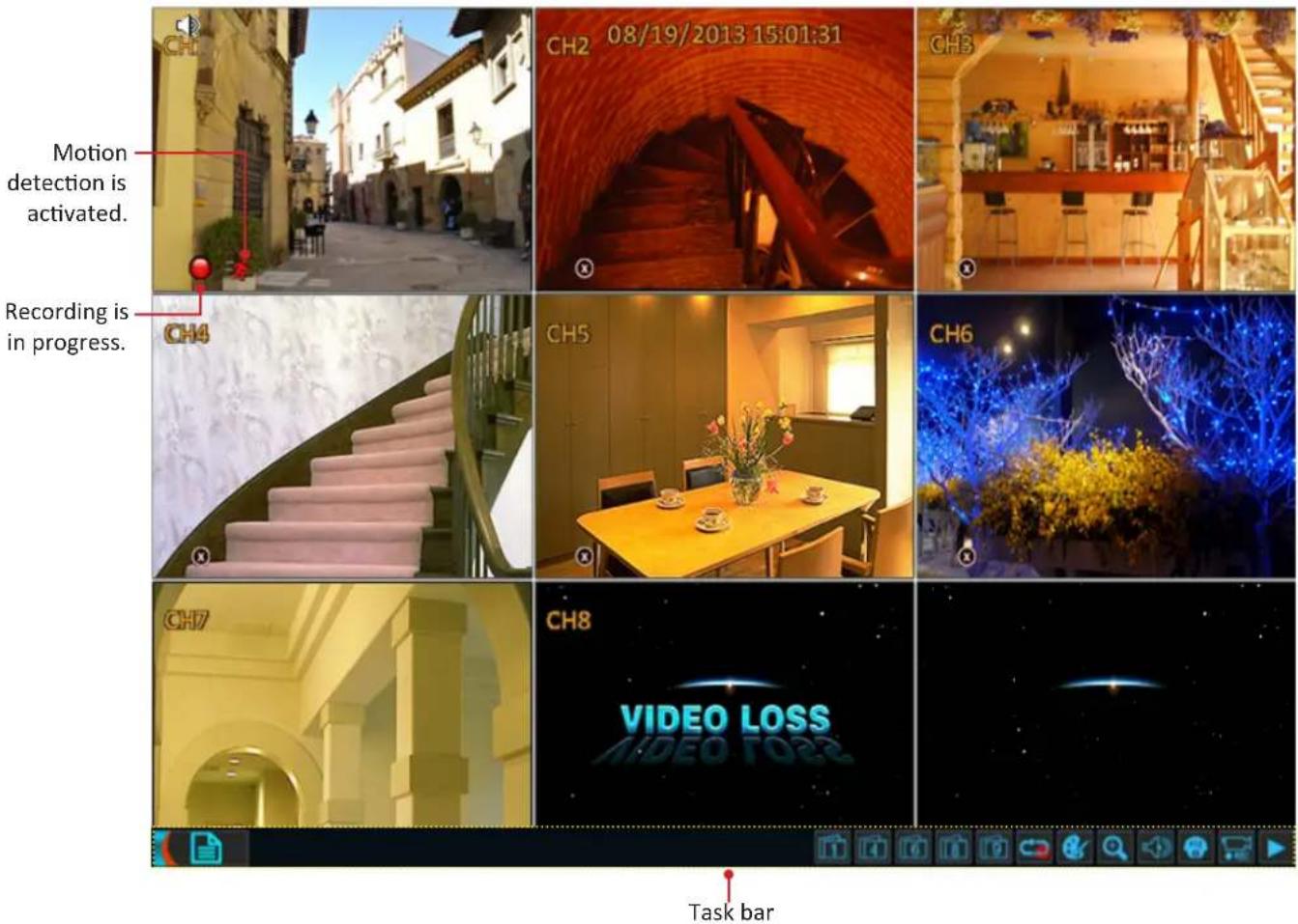
Main Screen
Once you turn on the DVR, the live view screen appears.

Note:
The number of channels displayed may vary depending on the DVR model. The illustration below is from a 8-channel DVR.
Task Bar
To open the task bar, do one of the following:
• Right-click on any place on the screen.
- Press the Menu button on the remote control.
To access the Main menu or other common functions, click the respective icon.

Click to enter the Main menu. See "Main Menu" on page 31.

Click and select the desired channel to be displayed in full screen.

Click to switch to 4-window display.
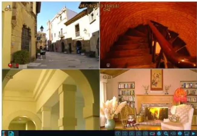
natural_image
Four-panel image showing a historic street scene with arched colonnades, a brick archway interior, and a living room interior (no visible text or symbols)
Click to switch to 6-window display.
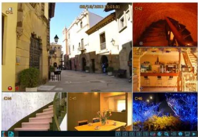
natural_image
Collage of interior scenes including a historic European-style building, stone staircase, dining table, and illuminated tunnel entrance (no visible text or symbols)
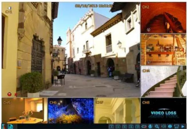
Click to switch to 8-window display.

Click to switch to 9-window display.
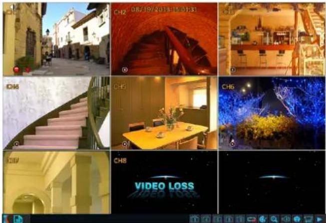

Click to start/stop rotation of channel display.
To customize the auto sequence order, see "Auto Sequence" on page 36.

Click to access the Color Setup menu.
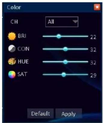
To adjust image hue, brightness, contrast, and saturation settings, select the channel and drag the slider bar to adjust the color item setting. Click Apply to save the settings.

Click to enlarge certain area on the screen. Click and drag the left mouse button to frame an area on the screen that you want to zoom in.
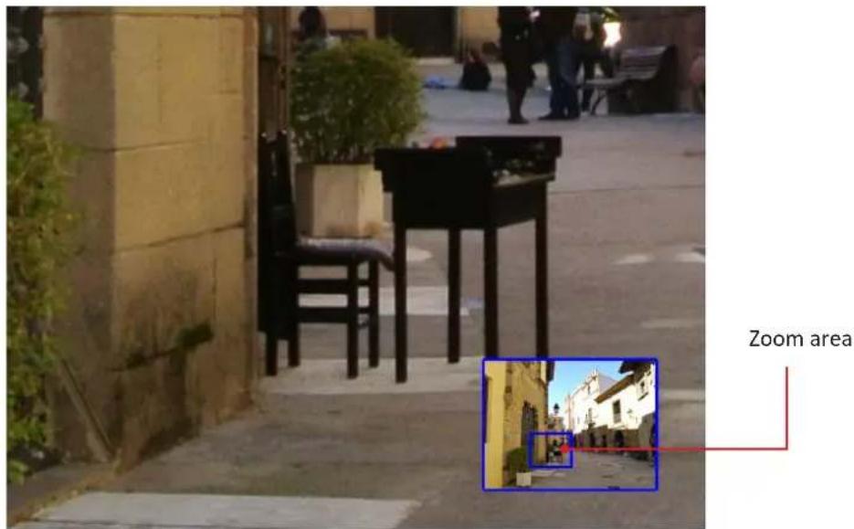
The selected location will be enlarged and displayed as full screen.

Click to access the Volume Control bar.

Drag the slider to adjust the volume level.
Click to turn mute on or off.

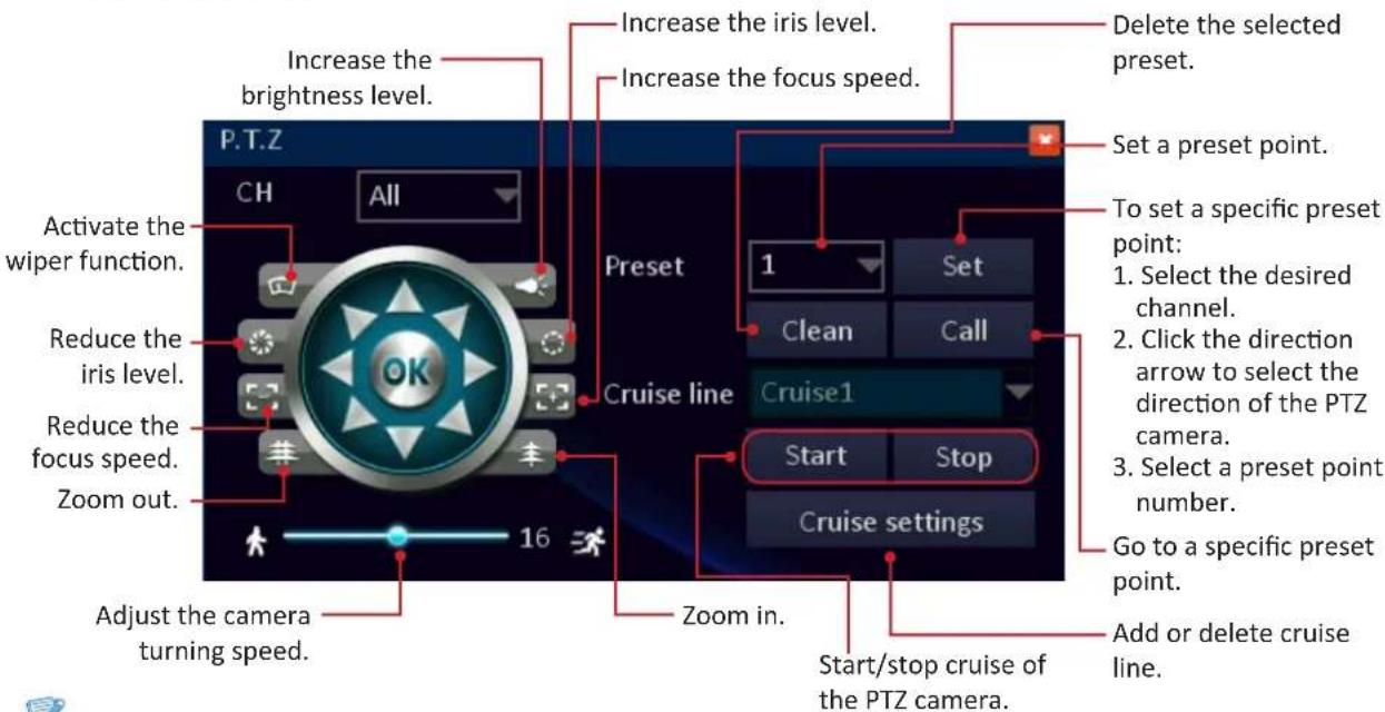
Click to access the PTZ Control panel.
- Select the desired channel.
- Click the direction arrow to select the direction of the PTZ camera. For the other function settings, see below:

Note:
These settings are only applicable if a PTZ speed dome is properly installed on DVR via RS-485 connection.

Click to start/stop manual recording.

Click to open the video playback screen.
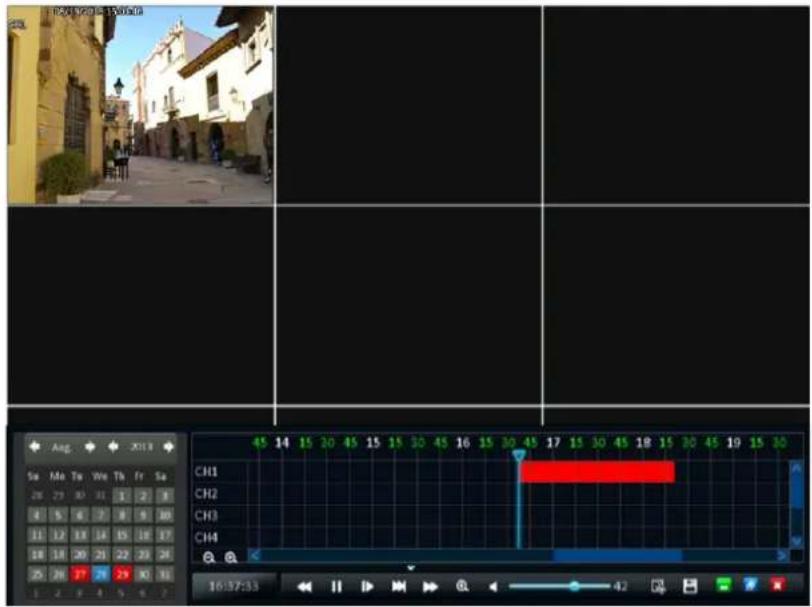
Select the desired time slot that you want to play. To play in full screen, click a channel. See "Playing Videos" on page 57 for more details.
Configuring DVR Settings
Main Menu
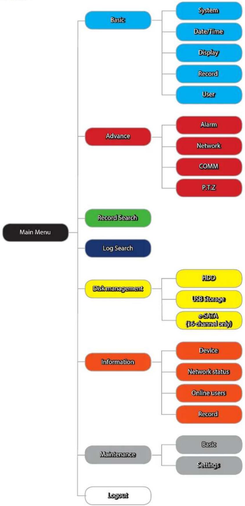
flowchart
graph TD
    A["Main Menu"] --> B["Basic"]
    A --> C["Advance"]
    A --> D["Record Search"]
    A --> E["Log Search"]
    A --> F["Disk management"]
    A --> G["Information"]
    A --> H["Maintenance"]
    A --> I["Logout"]

    B --> J["System"]
    B --> K["Date/Time"]
    B --> L["Display"]
    B --> M["Record"]
    B --> N["User"]

    C --> O["Alarm"]
    C --> P["Network"]
    C --> Q["COMM"]
    C --> R["P.T.Z"]

    F --> S["HDD"]
    F --> T["USB Storage"]
    F --> U["e-SAIA (16-channel only)"]

    G --> V["Device"]
    G --> W["Network status"]
    G --> X["Online users"]
    G --> Y["Record"]

    H --> Z["Basic"]
    H --> AA["Settings"]

    I --> AB["Record"]
Click to enter the Main menu.
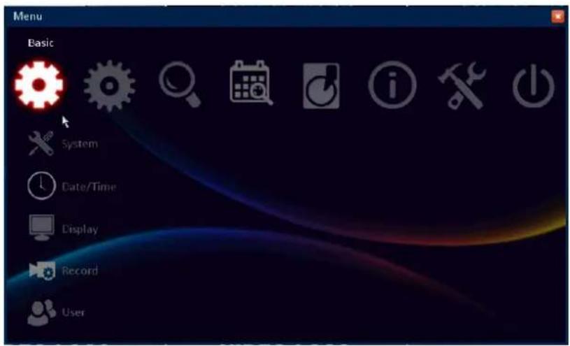
Select one of the menu options and configure the necessary settings:

Basic menu
Configure the system, date/time, display, record, and user settings.

Advance menu
Configure alarm, network, internet application, and PTZ settings.

Record Search menu
Search the recorded video.

Log Search menu
Search the recorded videos.

Disk Management menu
Display the HD/USB storage status and format the device.

Information menu
Display the system, network, user, and video settings information.

Maintenance menu
Update the firmware, export/import the system settings, and restore the default settings of the DVR.

Logout
Exit the menu.
Basic Menu
System Setup
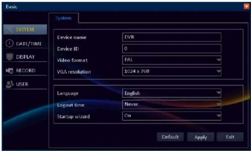
Device name: Enter the desired name for the DVR. The name can be composed of alphanumeric characters and is used to identify this device in your list of activated DDNS accounts.
Device ID: Enter the desired ID for the DVR. The device ID, identifying the DVR, can only be composed of numbers and cannot be the same with other IDs when multiple DVRs are connected in the same network.
Video format: Choose between NTSC and PAL, depending on your geographical location.

Note:
NTSC - for the USA, Canada, Mexico, Japan, Korea and some other regions.
PAL - for UK, Europe, Australia and some other areas.
VGA resolution: Select how many pixels the DVR will output. It is recommended to use as high resolution as possible that matches with your monitor's highest resolution.
Language: Select the language you wish the menu items to be displayed in.
Logout time: Select the time period for menu time out.
Startup wizard: The Setup Wizard will run automatically the first time you start the DVR. The wizard will guide you through all the basic settings you need to configure for getting your DVR start up and functioning.

Note:
To prevent the Wizard Setup screen appear every time the system reboots, set the setting to Off.
Date/Time Setup
Date/Time
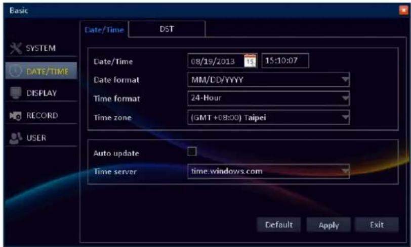
Date/Time: All video footages are stored on the HDD based on their time stamps. Make sure you set the correct system date and time.

Note:
You can click on on-screen calendar ( ) or type in the current date manually.
Date format: Select the format you prefer the date to be displayed.
Time format: Select the format you wish the time to be displayed. The options are 24 hours or 12 hours.
Time zone: Select the time zone in your location.

Note:
In the USA, EST (Eastern Standard Time) is GMT -5:00, where PST (Pacific Standard Time) is GMT -8:00. The UK is GMT +0:00, and the East Coast of Australia is GMT +10:00.
Auto update: Click to automatically set the date and time according to the network.
Time Server: Choose the time server that will keep track of DST settings (see in the following section).

Note:
If you choose to use the Time Server, make sure your DVR has a constant Internet connection.
DST (Daylight Saving Time)
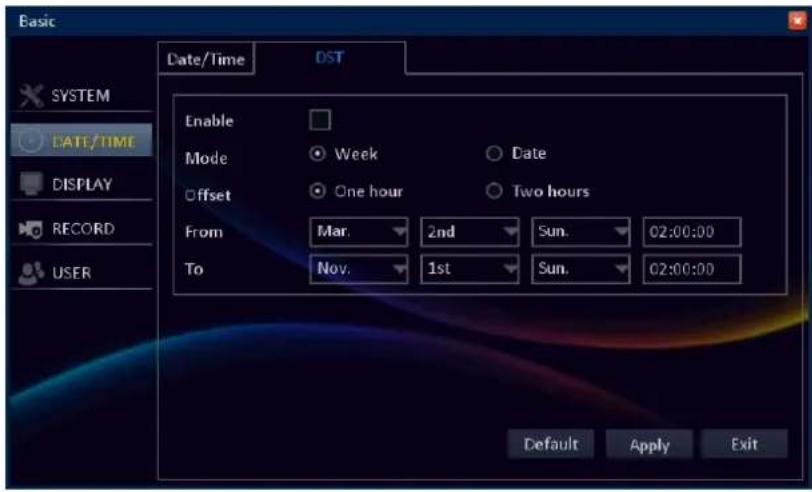
You can allow the DVR to automatically update its internal clock when daylight saving starts and ends.
Enable: Check this option to allow the DVR automatically adjust the time for DST. To disable, uncheck this option.
Mode: Select the DST mode.
- Week: Enter the Start Time and End Time information by selecting the starting/ending month, week, day, and entering the starting/ending time.
- Date: Enter the Start Time and End Time information by entering the starting/ending date and time.
Offset: Select the amount of time to offset for DST.
From/To: Enter the Start Time and End Time information when the DST begins and ends at your location.
Display Setup
Display
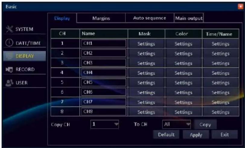
Name: Enter your desired channel title to be displayed on the screen.
Mask: You can create and shape a privacy zone (mask) which hides part of the image on the selected channel. To do so, select Settings and enter the Mask submenu. See "Privacy Zone Settings" on page 35.
Color: Adjust image hue, brightness, contrast, and saturation settings. Select Settings enter the Color submenu. See "Color Settings" on page 35.
Time/Name: Choose to hide or display the recording data (time, date, or channel) during recording. See "Overlay Settings" on page 36.
Copy CH/To CH: Select to copy the current settings to all channels or one specific channel. Click the arrow to select an option and then click Copy.
After all settings are complete, click Apply.
- Privacy Zone Settings
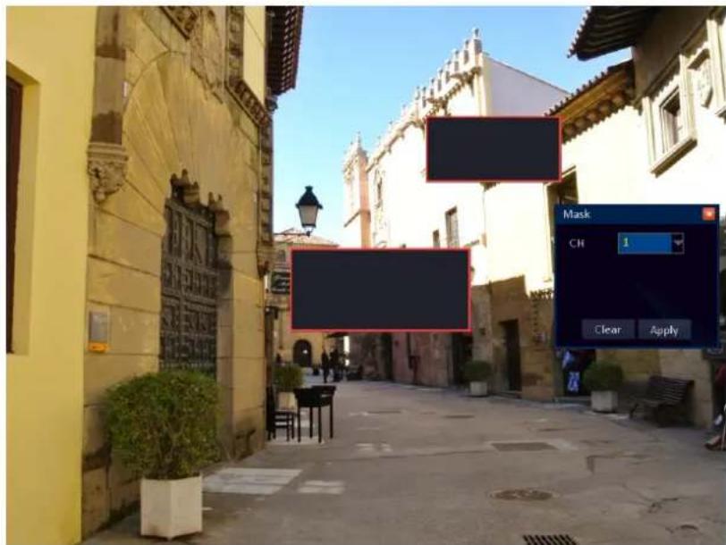
Defining a privacy zone in the channel allows to block a portion of the channel with a black box.
To add a privacy zone, in Mask, click Settings and select the channel that you want to set the privacy.
Drag the mouse to frame an area on the screen that you want to mask. The black box indicates the area for masking. You can set up to 4 mask areas.
Click Apply to save the settings.
- Color Settings
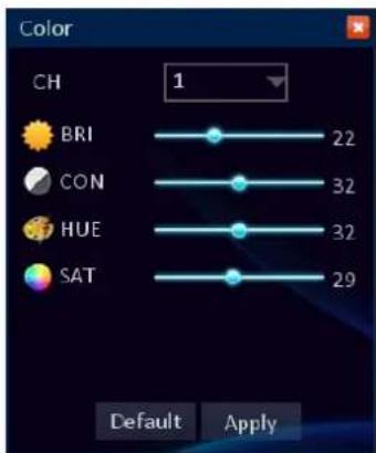
In Color menu you can configure the brightness, contrast, hue and saturation settings per channel.
Brightness (BRI): Defines how bright the image appears on the display.
Contrast (CON): Increases the difference between the darkest black and the whitest white in the image. Modify the contrast if the sections of the image "grey out".
Note:
Setting the contrast parameter too high will degrade the image quality. Hue: Changes the color mix of the image.
Saturation (SAT): Alters how much color is displayed in the image. The highest the saturation, the brighter and vivid colors will appear to be. Setting this parameter too high can degrade the image quality.

Note:
All the changes to the image color settings affect your recordings!
Click Apply to save the settings.
- Overlay Settings
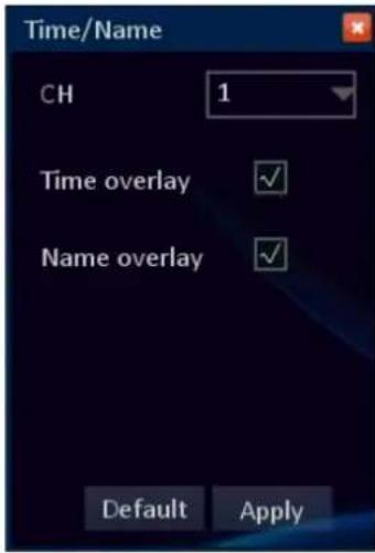
Use these settings to include a date/time and camera name on a video stream per channel.
In Time/Date, click Settings and select the channel that you want to set the overlay settings.
To include the date/time and/or channel name on the recorded file, check the respective box.
Click Apply to save the settings.
Margin
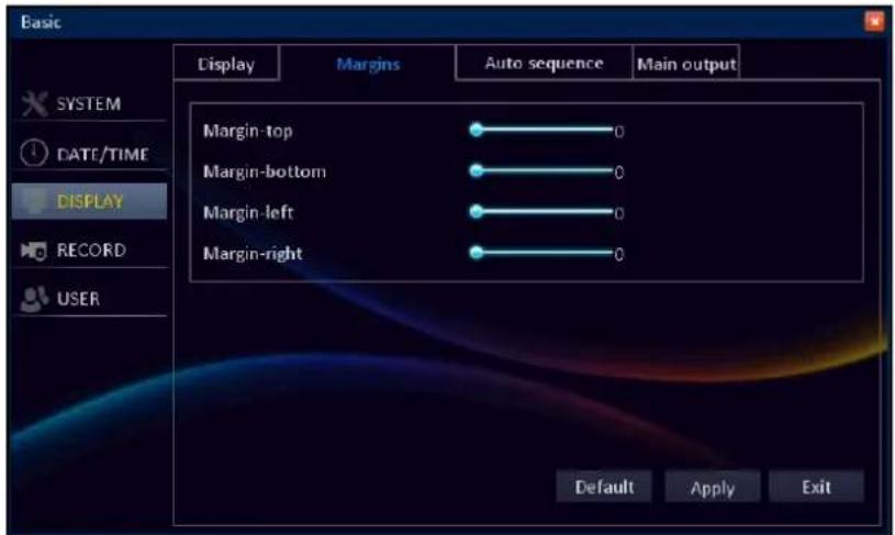
When the DVR is connected to a monitor, you can define the image size and position to be displayed on the screen.
Drag the slider bar to adjust the top, bottom, left and right margin setting.
Click Apply to save the settings.
Auto Sequence
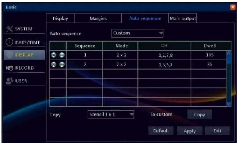
When auto sequence mode is activated (see "Task Bar" on page 26), the DVR will automatically cycle through all available channels, displaying each in turn expanded to fill the entire screen. The channels can be displayed on the screen stencil or customized pattern.
Auto sequence: Select the auto sequence type.
To customize the auto sequence order, select Custom and do the following:
- Click + to configure the new display setting including the display mode, channel layout, and dwell time settings.
- Click X to remove the selected settings.
Mode: Allows to configure how many channels are displayed on the screen. The available options include 1 x 1 (one channel in full screen), 2 x 2 (four channels), 3 x 3 (nine channels), 4 x 4 (sixteen channels) depending on the number of DVR channels..
Layout: Allows to configure in what order the channels appear on the screen, depending on the chosen Mode.
Dwell: Allows to configure how long the channels are displayed on the screen in an auto-sequence mode. The available period is from 1s \~ 300s.
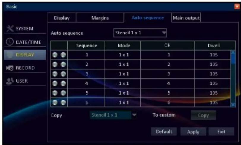
Copy: Copy the selected auto sequence type setting to Custom setting. Click Copy to copy the settings.

Note:
This function will overwrite the original customized settings. If you wish to use customized pattern while the customized settings have been applied then do not use Copy function.
Click Apply to save the settings.
Main Output
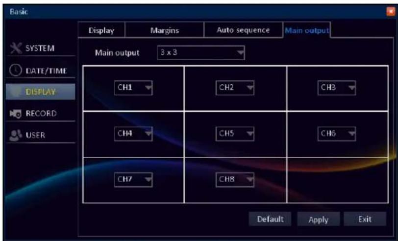
This menu allows you to configure the number and order of the channels displayed on the split window.
Main output: The available options include 1 x 1 (one channel in full screen), 2 x 2 (four channels), 3 x 3 (nine channels), 4 x 4 (sixteen channels), 6-split, 8-split, 10-split, 13-split, depending on the number of DVR channels. Then click on the channel name and select from the drop-down menu the desired channel you wish to be displayed.
Click Apply to save the settings.
Record Setup
Basic
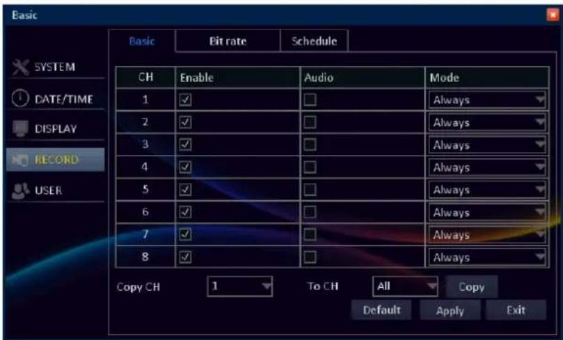
Set the audio function and recording mode for each channel.
Enable: Check to enable or uncheck to disable the record mode for a channel.
Audio: Check to enable the audio recording for a channel. Uncheck to disable this option.

Note:
This function requires a camera with the audio support or an external microphone.
Mode: Select the type of recording mode. There are two types of recording modes available: Always and Schedule.
Always: The DVR will continuously record for any period where Always mode is selected.

Note:
Make sure the space on hard disk is sufficient when using constant recording.
Schedule: The recording is performed according to a pre-defined schedule. To define the schedule, see "Schedule" on page 39.
Copy CH/To CH: Copy the current settings to all channels or one specific channel. Click the arrow to select an option and then click Copy.
After all settings are complete, click Apply.
Bit rate

The bit rate section allows you to configure the actual amount of data that the DVR will use to record a video. The parameters that can be configured is video resolution, frame rate, and quality settings for each channel.
Resolution: The two types of record modes are as follows: D1 (CIF/HD1/D1); 960H (WCIF/WHD1/WD1). The resolutions CIF, WCIF, WD1 (960H) can be selected only to channel 5 or higher channel.

Note:
If the record mode setting is set to 960H, it is recommended to use a 600 TVL or higher resolution camera.
Frame rate: Select how many images per second the DVR will record. According to the standard, "Real time" is 30fps (NTSC) or 25fps (PAL). With the resolution WD1 (960H) the recommended frame rate with 8 channels is 8fps, and with 16 channel is 6fps.
Quality: Select the video quality. Best means the lowest compression rate but larger video file size; Normal means the highest compression rate and smaller video file size.
Copy CH/To CH: Copy the current settings to all channels or one specific channel. Click the arrow to select an option and then click Copy. If you use the Copy All function with resolutions HD1, D1, WHD1, the resolutions are copied only to channels CH1 \~ CH4.
After all settings are complete, click Apply.
Schedule
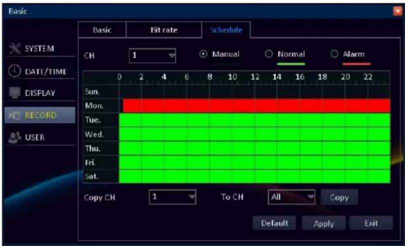
The schedule that is displayed on-screen applies only to one channel at a time.
There are three types of recording modes to choose from.
Manual: The recording is done manually. To start recording, you need to click on recording button(
Task Bar or press the Record button on remote control. See "Remote Control" on page 9 or "Task Bar" on page 26.
Normal: The DVR will continuously record for any period where Normal mode is selected.

Note:
Make sure the space on hard disk is sufficient when using constant recording.
Alarm: The DVR will only record when an alarm is detected. To know more on alarm settings and events, please see "Alarm Setup" on page 42.
CH: Select the channel you want to set the schedule.
Copy CH/To CH: Copy the current settings to all channels or one specific channel. Click the arrow to select an option and then click Copy.
After all settings are complete, click Apply.
- Recording Schedule Setup
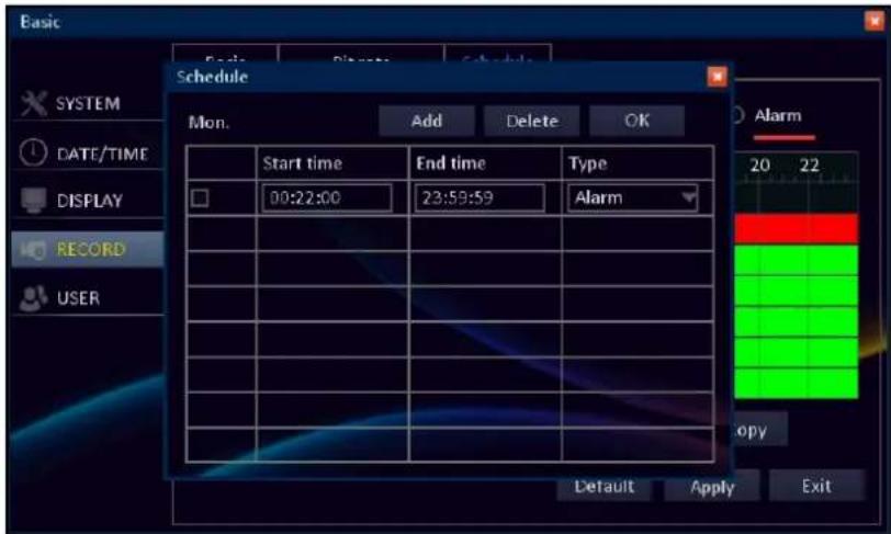
Click OK to save the settings.
You can also double-click the time slot to set the recording mode and schedule.
Start time/End time: Enter the Start time and End time information when the recording begins and ends.
Type: Select the recording mode.
To add additional recording schedule, click Add.
To delete a recording schedule, check the desired schedule box that you want to delete and click Delete.
User Setup
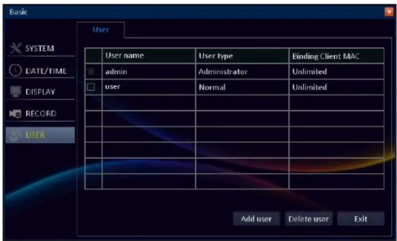
In User menu you can define and configure the various levels of access different users have to the DVR system.
By default, there is one administrator account. The administrator account's user name is "admin" and the password is "123456".

Note:
• We highly recommend you to change the password to protect your privacy.
- If the password is left blank then the connection via portable device (smart phone/pad) to the DVR will not be established.
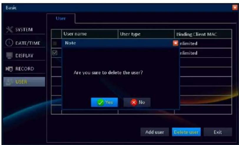
To configure other users, click Add user.
To delete the specific user, check the user box that you want to delete and click Delete user. A message appears, click Yes to confirm the operation.
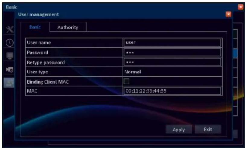
- Configuring Other Users
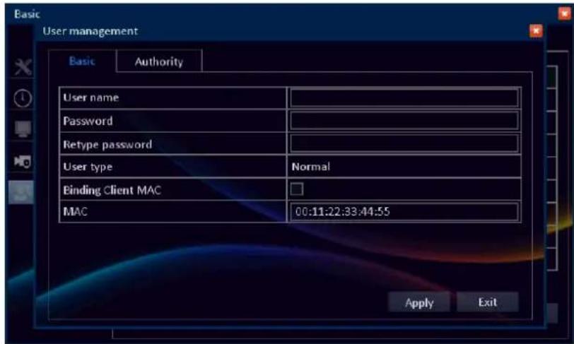
In Basic user menu you can specify the user name, password, MAC address and allow the binding client MAC or not.
User name: Select a name for the user you want to define. The best usernames are short and relevant to the speciality of the user they're intended for.
Password: Can be composed of numbers from 0 to 9 and letters. The maximum length is 16 characters.
Retype password: Must exactly match with the password for the specific user.
User type: The Administrator type is binded directly to the administrator account. The user type for all other users is Normal.
Binding Client MAC (Media Access Control): When this feature is enabled then the DVR can authenticate the client PC by the MAC address in combination with the specific DVR user name.
For example, the user of the DVR is "kguard" and the binding MAC address is: 00:11:22:33:44:55. Therefore only the PC with MAC address 00:11:22:33:44:55 and logged in user "kguard" can remotely connect to the DVR via Web Client program.
MAC: Client device's MAC address allows the DVR to identify the connecting device during the remote session. The MAC address should be entered as a 12-digit hexadecimal code, separated by colons. Example: 00:11:22:33:44:55.
Click Apply to save the settings.
• Editing Account Information
Double-click the desired account that you want to edit. Click the respective item and modify the necessary settings.
Click Apply to save the settings.
• Authorizing Other Users
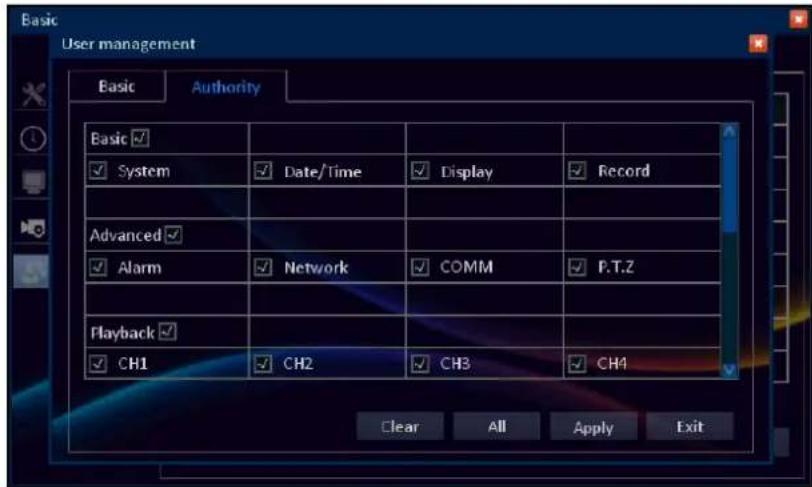
The administrator can grant access rights to users in the following categories:
- Basic (system, data/time display, record)
• Advanced (Alarm, Network, COMM, P.T.Z) - Playback (CH1 \~ CH8)
- Backup (CH1 \~ CH8)
- Remote monitor (CH1 \~ CH8)
- Disk, P.T.Z control, Log
Select the check box of the corresponding menu that you want to allow the user to access.
Click Apply to save the settings.
Advance Menu
Alarm Setup
Motion
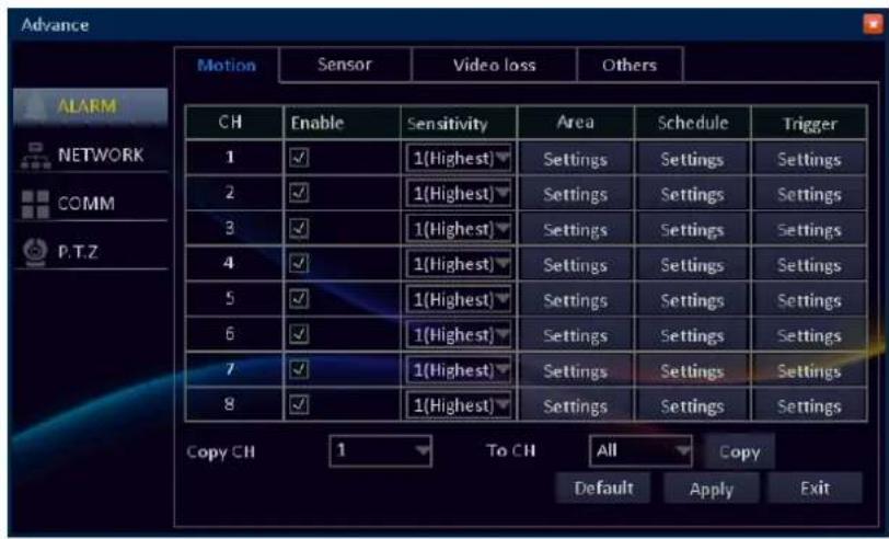
About Motion Detection
The DVR detects the motion by comparing one frame with the next. A sufficient (previously defined) amount of difference is interpreted as motion. As a result, the DVR is able to detect when there is a change in the picture and initiate the recording.

Note:
- It is advised to avoid using wireless cameras with any of the motion recording equipment. The wireless technology is sensitive to interference, and therefore common issues like static and image distortion might trigger the motion detection unintentionally.
- It is recommended to set the sensitivity level at the moderate level so that the DVR only record the particular scene when 'motion' is detected. If it is set at the highest level, the DVR may record continuously.
- Do not use PTZ system and motion detection function at the same time to avoid wrong 'motion' interpretation.
Area: Select the area for motion detection alarm. See "Set Motion Detection Area" on page 43.
Schedule: Motion detection is triggered only based on the start and end time described in the schedule. See "Motion Schedule Setup" on page 44.
Trigger: Configure the actions to be taken when motion is detected. See "Motion Trigger Settings" on page 44.
Copy CH/To CH: Copy the current settings to all channels or one specific channel. Click the arrow to select an option and then click Copy.
After all settings are complete, click Apply.
- Set Motion Detection Area
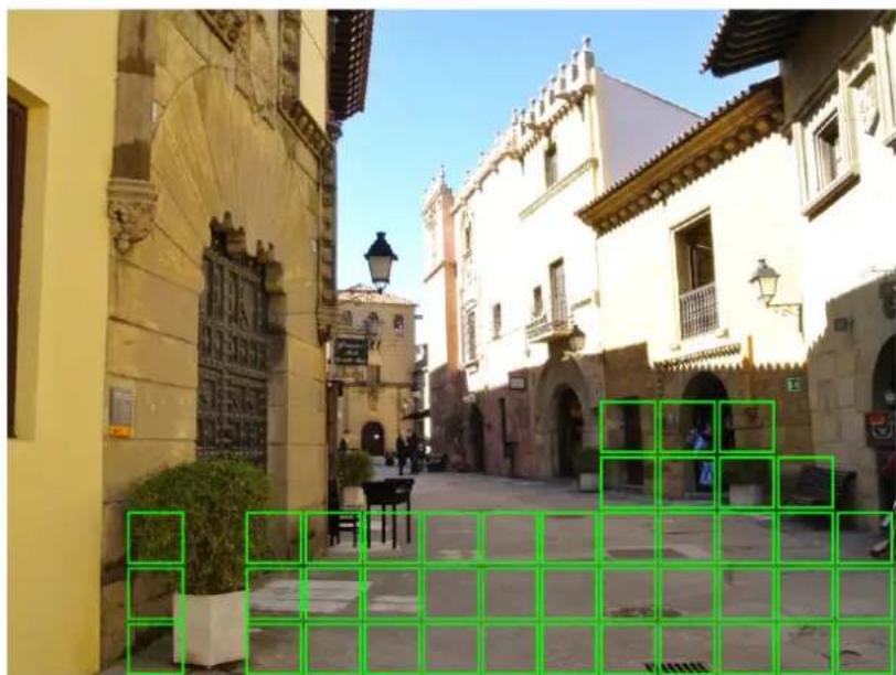
natural_image
Street view of a historic European-style building complex with yellow walls, stone carvings, and a green overlay grid (no visible text or symbols)In Area, click Settings and specify the area for motion detection alarm.
By default, the whole screen is marked for motion detection (green block).
• To disable motion detection on an area, click the grid cursor and then drag the mouse to highlight the scope to unmark the area.
- Right click to close the setup screen.

Note:
To avoid getting false triggers, it is recommended to set the motion detection area at an appropriate location such as door, window, etc.
- Motion Schedule Setup
Prior defining the motion schedule, make sure the channel you want to associate it with is Enabled.
In Schedule, click Settings and double-click the time slot to set the schedule.
Start time/End time: Enter the Start time and End time information when the motion detection begins and ends.
To add additional schedule, click Add.
To disable motion detection at the scheduled time, check the desired schedule box that you want to delete and click Delete.
Copy/To: Copy the current settings to other days. Click the arrow to select an option and then click Copy.
Click OK to save the settings.
- Motion Trigger Settings
About Motion Detection
In general, the motion detection can be used with almost all static and wired cameras. However, PTZ systems are incompatible with motion detection, avoid allowing motion detection on a channel which has a PTZ system connected to it.
False Triggers
It is very important to set the motion detection on a suitable sensitivity level. If you set the motion detection at a high sensitivity levels (4 or lower) then the frequency of false alarm events increases. Vice versa if the sensitivity level is too low (20 or higher), you might increase the risk that an important motion event will not trigger the motion detection to record. Therefore during the DVR system configuration, it is advised to check the motion detection in normal and low light conditions (during the day and night).
Also, false triggers may be caused by severe weather conditions, for example lightening and heavy rain. To minimize the false triggers, do the following:
- Adjust the Image Settings to configure the brightness and contrast, see "Color Settings" on page 35.
- Make limitations to the motion sensitive areas, selecting only the area where the target would most probably be. Hence, turn off the motion sensitivity to any area a target cannot move.
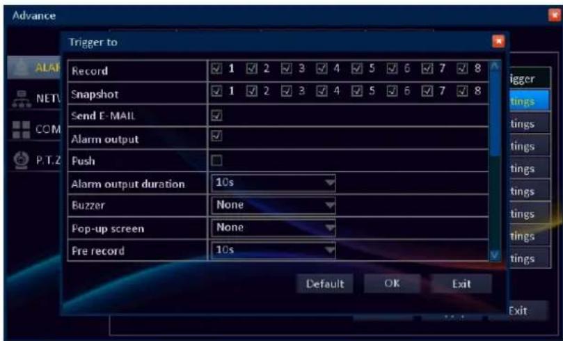
In Trigger, click Settings to configure the actions to be taken when motion is detected.
Record: Check the box to select the channel(s) to record when the motion is detected.
Snapshot: Check the box to select the channel(s) to take a snapshot when the motion is detected.
Send E-MAIL: Check to enable e-mail alarm notification. If the function is enabled, the system will send the alarm messages / snapshots (snapshot option must be enabled first) to the specified e-mail address.

Note:
Be sure to complete the E-mail and DNS server settings before enabling this function.
Alarm output: If an alarm device is connected, check the box to make the device sound the alarm when motion is detected.
Push: Check the box to enable Push Event function on Mobile/Pad when the motion is detected.

Note:
To use Push Event function, you need to do the following:
- Enable MyKguard in DVR (see "MyKguard" on page 51).
- Configure the DVR network connection parameters.
- Download KView QR on your smart phone/pad. If you are using an iOS portable device, you need to enable the Push Event function on app too.
Alarm output duration: Select the alarm sound duration of the I/O alarm device.
Buzzer: Set the buzzer duration when the motion is detected.
Pop-up screen: Select the corresponding channel will be displayed in full screen when the motion is detected.
Pre record: Set the recording period in seconds just before the motion triggers recording.
Post record: Set the recording period in seconds after the motion triggered recording has finished.
P.T.Z: Check the box to activate cruise of the PTZ camera on the specified channel when the motion is detected.
Click OK to save the settings.
Sensor
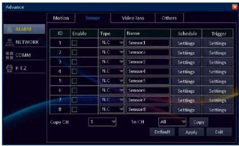
Customize the sensor settings.
Enable: Click to enable sensor alarm.
Type: Select the sensor type between N/O (Normal Open) and N/C (Normal Close).
Please check the documentation of sensors to learn the correct value to use.
Name: Specify the sensor name.
Schedule: Set the sensor detection schedule. See "Sensor Schedule Setup" on page 46.
Trigger: Configure the actions to be taken when sensor is triggered. See "Sensor Trigger Settings" on page 46.
Copy CH/To CH: Copy the current settings to all channels or one specific channel. Click the arrow to select an option and then click Copy.
After all settings are complete, click Apply.
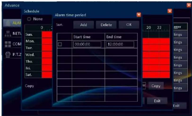
- Sensor Schedule Setup
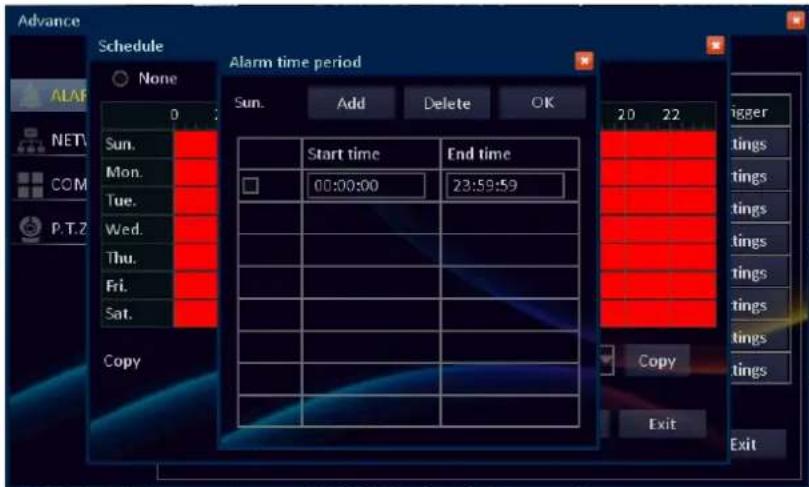
In Schedule, click Settings and double-click the time slot to set the schedule.
Start time/End time: Enter the Start time and End time information when the sensor detection begins and ends.
To add additional sensor detection schedule, click Add.
To disable sensor detection at the scheduled time, check the desired schedule box that you want to delete and click Delete.
Copy/To: Copy the current settings to other days. Click the arrow to select an option and then click Copy. Click OK to save the settings.
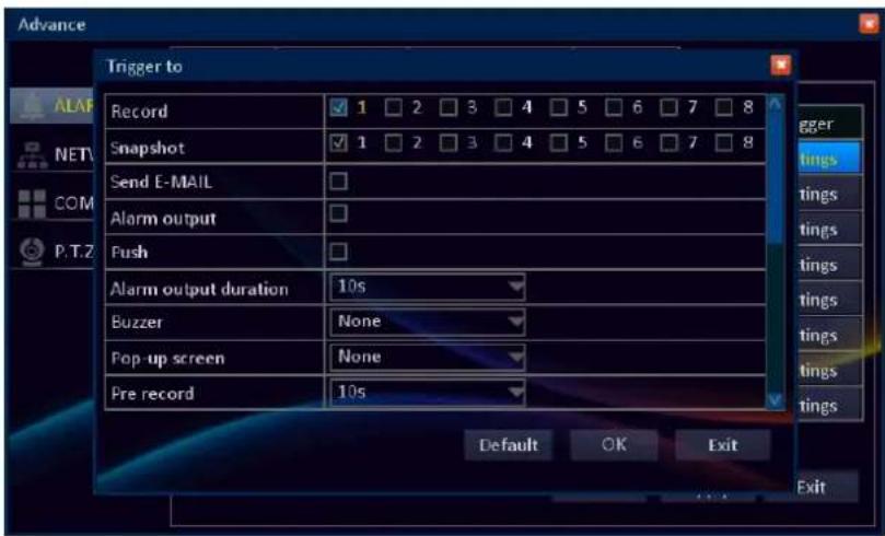
- Sensor Trigger Settings
In Trigger, click Settings to configure what actions are taken when the sensor detects an abnormal situation.
Record: Check the box to select the channel(s) to record when the sensor is triggered.
Snapshot: Check the box to select the channel(s) to take a snapshot when the sensor is triggered.
Send E-MAIL: Check to enable e-mail alarm notification. If the function is enabled, the system will send the alarm messages / snapshots (snapshot option must be enabled first) to the specified e-mail address.

Note:
Be sure to complete the E-mail and DNS server settings before enabling this function.
Alarm output: If an alarm device is connected, check the box to make the device sound the sensor when triggered.
Push: Check the box to enable Push Event function on Mobile/Pad when the sensor is triggered.

Note:
• To use Push Event function, you need to do the following:
- Enable MyKguard in DVR (see "MyKguard" on page 51).
- Configure the DVR network connection parameters.
- Download KView QR on your smart phone/pad. If you are using an iOS portable device, you need to enable the Push Event function on app too.
Alarm output duration: Select the alarm sound duration of the alarm device.
Buzzer: Set the buzzer duration when the sensor is triggered.
Pop-up screen: Select the corresponding channel will be displayed in full screen when the sensor is triggered.
Pre record: Set the recording period in seconds just before the alarm sensor input (before the alarm sensor triggers the recording).
Post record: Set the recording period in seconds after the alarm sensor input (after the alarm sensor triggered recording has finished).
P.T.Z: Check the box to activate cruise of the PTZ camera on the specified channel when the sensor is triggered.
Click OK to save the settings.
Video Loss
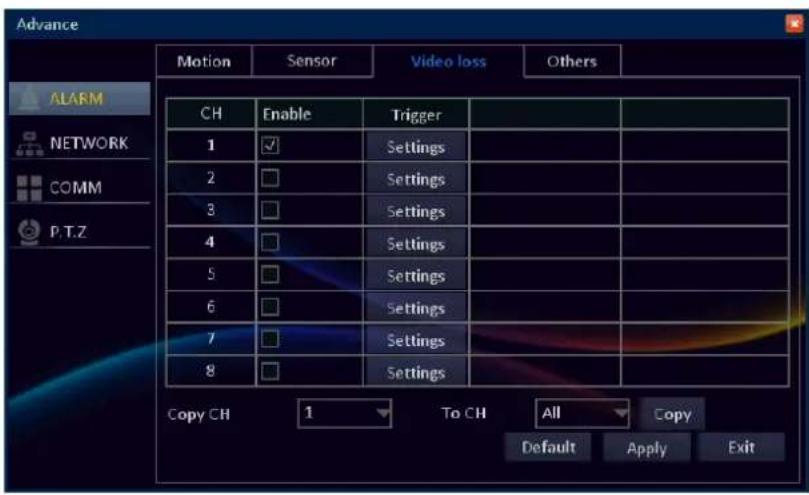
Video loss is regarded as a potential alarm event, and is considered to occur any time that the DVR does not receive an active signal on any of its inputs.
The default behavior of the DVR, when a channel has no incoming video signal, is simply to display "Video Loss" in light blue text on a black background over the associated channel. If you're not using all the inputs on your DVR, then some channels will be in constant Video Loss state. Make sure that you don't Enable a video loss action for these channels.
Enable: Click to activate video loss monitoring function.
Trigger: Configure the actions to be taken when the DVR does not receive any video input signal from the connected camera(s). The settings configuration is similar to Sensor Trigger. See "Sensor Trigger Settings" on page 47.
Copy CH/To CH: Copy the current settings to all channels or one specific channel. Click the arrow to select an option and then click Copy.
After all settings are complete, click Apply.
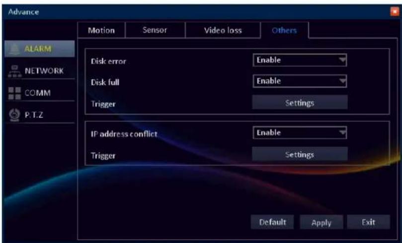
Others
After all settings are complete, click Apply.
Customize the event(s) alarm settings.
Disk error: Select Enable to trigger the alarm if the DVR has trouble to access or detect the hard disk drive.
Disk full: Select Enable to trigger the alarm when the hard disk drive is full.
IP address conflict: Select Enable to trigger the alarm if the DVR has detect another device on the same network using the same IP address.
Trigger: Configure the actions to be taken when the event type occurs. See "Event Trigger Settings" on page 49.
• Event Trigger Settings
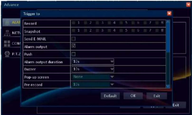
Alarm output: If an alarm device is connected, check the box to make the device sound the alarm when triggered.
Push: Check the box to enable Push Event function on Mobile/Pad when the event type occurs.
In Trigger, click Settings to configure the actions to be taken when the event type occurs.
Send E-MAIL: Check to enable e-mail alarm notification. If the function is enabled, the system will send the alarm messages to the specified e-mail address.

Note:
Be sure to complete the E-mail and DNS server settings before enabling this function.

Note:
• To use Push Event function, you need to do the following:
- Enable MyKguard in DVR (see "MyKguard" on page 51).
- Configure the DVR network connection parameters.
- Download KView QR on your smart phone/pad. If you are using an iOS portable device, you need to enable the Push Event function on app too.
Alarm output duration: Select the alarm sound duration of the alarm device.
Buzzer: Set the buzzer duration when the event type occurs.
P.T.Z: Check the box to activate cruise of the PTZ camera on the specified channel when the event type occurs.
Click OK to save the settings.
LAN
To access the DVR over local area network, you need to configure the LAN parameters of your DVR
Prior configuring the LAN interface, confirm the type of internet connection you are using and the related network connection parameters with your Internet Service Provider (ISP) or network administrator to complete the setup.
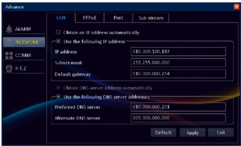
Obtain an IP address automatically: Select if you are using DHCP connection.
With Dynamic Host Configuration Protocol (DHCP) service, your router will automatically assign an IP address to your DVR connected to the network.
Use the following IP address: Select and configure it if you are using Static IP connection. With Static IP connection, your DVR is most likely connected to a DSL modem and your ISP has supplied you with a predefined IP for your Internet connection.
Obtain the following information from your network administrator or your Internet Service Provider (ISP), and type in accordingly.
IP address: The address that identifies the DVR in the electronic network. Your DVR uses IPv4 addressing, which consists of four groups of numbers between 0 to 255, separated by periods. For example, "192.168.1.35". Make sure that no other device in the LAN does not share the same IP address.
Subnet mask: Subnet mask defines a range of IP addresses that can be used in a network. If IP address is like a street where you live then subnet mask is like a neighborhood. The subnet address consists of four groups of numbers, separated by periods. For example, "255.255.255.0".
Default gateway: The address of the node (router) on a TCP/IP network via is established the entrance into a network and vice versa.
Obtain DNS server address automatically: Select to let the DVR to automatically choose a DNS server. This option is only available if you are using DHCP connection.
Use the following DNS server addresses: Select to manually configure the DNS server parameters.
Preferred DNS server: Specify the preferred DNS server address.
Alternate DNS server: Specify the backup DNS server address. Backup DNS server address is used when the preferred DNS server is not accessible.

Note:
- Please contact your local ISP (Internet Service Provider) to obtain the correct DNS Server parameter.
- If you want to use the E-mail notification, Preferred DNS server settings must be properly configured.
After all settings are complete, click Apply.
PPPoE
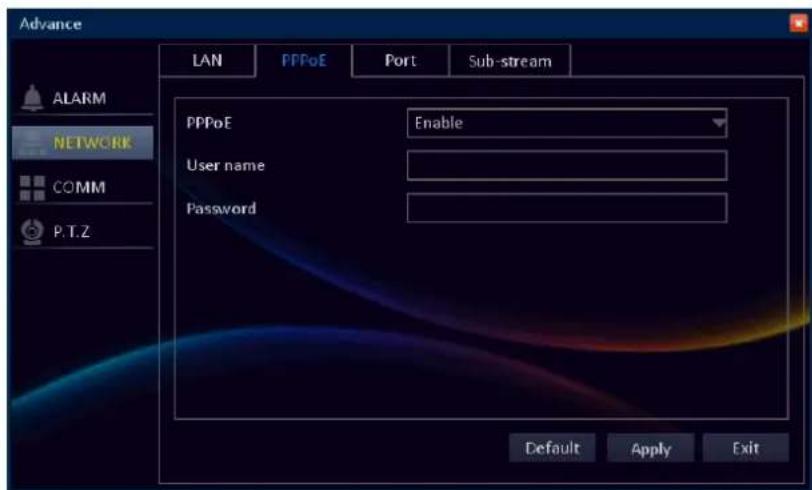
After all settings are complete, click Apply.
Select if you are using PPPoE connection. With PPPoE (Point-to-Point Protocol over Ethernet), your DVR is most likely connected to a DSL modem, and your ISP has supplied you with an authentication user name and password to the Internet.
PPPoE: Select Enable to use PPPoE network connection.
User name: Enter the user name that your ISP has supplied you.
Password: Enter the password that your ISP has supplied you.
Port
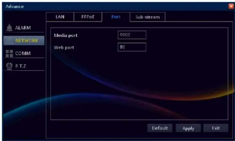

Note:
If you cannot use the either of the two default ports, 80 or 9000, the specified port may be occupied by other programs or it is being blocked by your service provider. Enter other port number. In this case, you need to add the port number after the IP address. For example, if you set the Web port as 85, you need to enter the IP address as "192.168.3.103:85".
Sub-stream
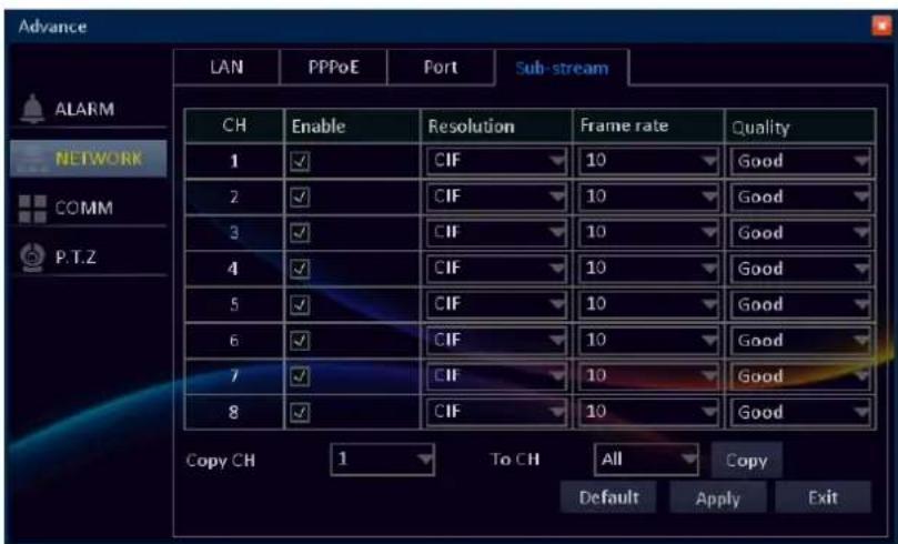
The sub-stream is the video stream that the DVR will send to remote devices via a network or the Internet. It is the lower-quality stream as a reduction in video size, using constant bit-rate and thus making it easier to send over a network.
Enable: Click to use sub-stream for network transfer.
Resolution: How many pixels compose the image. Choose between the following two options: CIF and QCIF. The CIF resolution is 352 x 240 pixels in size. It is suggested to use by higher end systems for remote Internet viewing (for multiple cameras uses a lot of bandwidth). QCIF resolution is 176 x 120 pixels in size and is one quarter the size of CIF resolution. It is advised to use for remote viewing from portable devices (example, cell phone).
Frame rate: The number of frames per second (fps) that the DVR will record. The recommended fps is 10.
Quality: Select the video stream quality.
Copy CH/To CH: Copy the current settings to all channels or one specific channel. Click the arrow to select an option and then click Copy.
After all settings are complete, click Apply.
Communication Setup
MyKguard
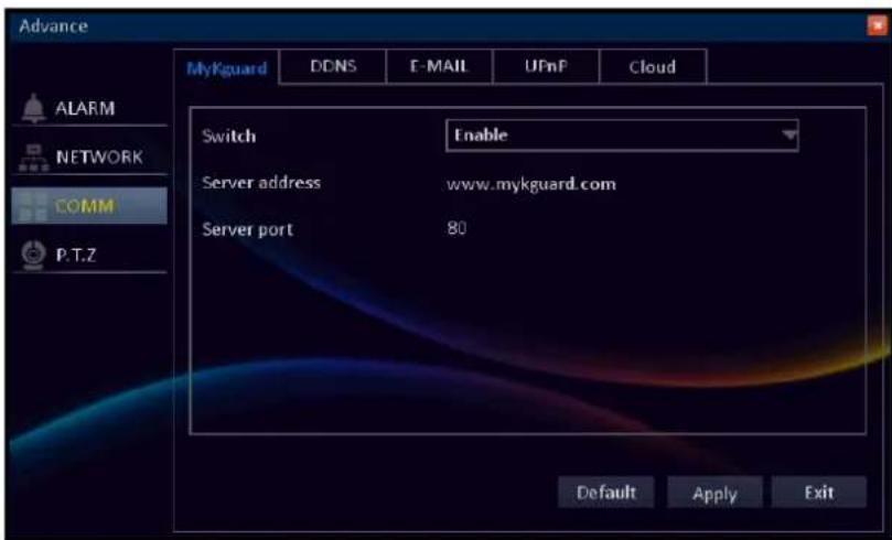
Switch: To enable remote live view the DVR via MyKguard, you need to enable the function first prior accessing MyKguard (http://www.mykguard.com).
Note:
- For viewing DVR live view, using MyKguard, does not require to configure the port forwarding in router.
- For accessing MyKguard, it is advised to use Internet Explorer 8 or above web browser.
- For remote live view from a single DVR, use Quick Login. For remote live view from multiple DVRs, use Log in MyKGUARD. See "Basic Connection for Remote Live View on MyKguard" on page 17.
Server address: Display MyKguard server address.
Server port: Display the server port number.
DDNS
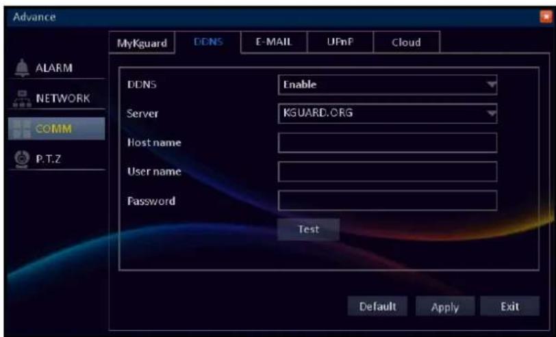
DDNS (Dynamic DNS) is a service that registers a domain name and the floating IP address with a DDNS server so that the domain name can be routed to the IP address even if the IP is changed in a dynamic IP system.

Note:
To use this feature, make sure in the following:
- You are using a broadband/high-speed/DSL/Cable Internet connection from the DVR side and the location you want to connect to the DVR.
- Your router supports DDNS or DynamicDNS. Consult with your Internet Service Provider for this service.
- You need to create a DDNS account with KGUARD.org server, see http://www.kguard.org or an account on DynDNS website.
DDNS: Select Enable to enable this function.
Server: Select the DDNS server.
Host name: Enter the domain name you registered on DDNS server. If the registered domain name is 123ABC.KGUARD.ORG, the IP address you type on web browser when you browse Web Client is http://123ABC.KGUARD.ORG.
User Name: Enter the DDNS User Name.
Password: Enter the DDNS password.
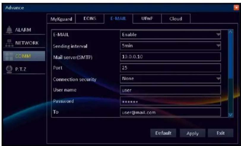
When the e-mail settings are properly configured and the function is activated, the DVR will automatically send a notification e-mail when events occur, such as when motion is detected or the HDD fails at the specified channel, day, and time.

Note:
Be sure that the DVR network connection and DNS server address are properly configured before proceeding with the e-mail setup.
Enable: Select Enable to activate the e-mail notification function.
Sending interval: Select an e-mail sending interval.
Mail server(SMTP): Enter the SMTP Server of the sending e-mail server. If you do not know the SMTP mail server address, please consult with the e-mail service provider or check the information on their web page.
Port: Enter the SMTP port of the sending e-mail server.

Note:
By default, the SMTP port is 25 for e-mail without SSL verification. For Gmail server or for e-mail that needs SSL Verification, the SMTP port is 465, by default. Check with your ISP for the correct setting.
Connection security: If your e-mail server needs the SSL (Secure Sockets Layer) or TLS (Transport Layer Security) verification, select SSL/TLS. Check with your e-mail service provider for the applicable setting.
User name: Enter the e-mail address of the sender.
Password: Enter the password of the sender's e-mail.
To: Enter the e-mail address where the notification e-mail is to be sent.
CC: Enter the e-mail address that you want to copy to. You can set up to 4 e-mail addresses.
Test: Click to send a test e-mail to the recipient's e-mail address.
After all settings are complete, click Apply.
UPnP
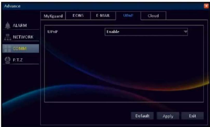
UPnP: (Universal Plug and Play) is an universal protocol for widespread plug-and-play devices to ease the network implementation. Many routers that support UPnP do not come with the feature enabled by default. If this function does not work, be sure to check if UPnP setting is enabled.
Enable: Select Enable to activate the UPnP function.
After all settings are complete, click Apply.
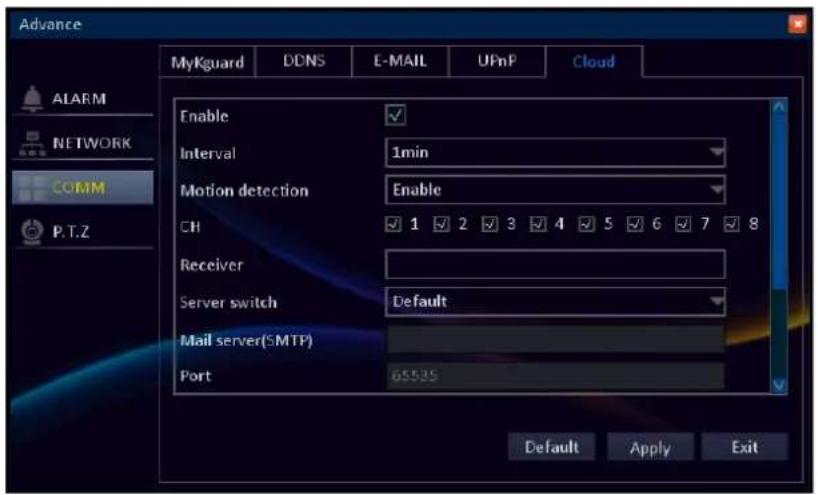
Cloud
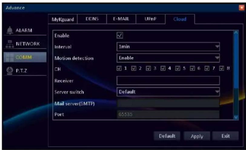
At present, your DVR supports the Dropbox cloud storage. Before setting up the cloud storage on the DVR, make sure your Dropbox account has been created and active (Dropbox website: www.dropbox.com) and the network settings of your DVR has been configured properly.
Enable: Check the box to enable the cloud storage function.
Interval: Select the interval time between uploading snapshots to the cloud storage.

Note:
To 1 minute interval option you can choose only 4 channels.
Motion detection: Select Enable if you want the DVR to upload snapshots when motion is detected.
CH: Check the respective channel box to upload the channel snapshots.
Receiver: Enter your e-mail account to receive the cloud storage activation link.
Server switch: Select Default and click Active Cloud directly.

Note:
If the Server switch setting is set to Customer, you need to complete the following settings before clicking Active Cloud:
Mail server(SMTP): Enter the SMTP Server of the sending e-mail server. If you do not know the SMTP mail server address, please consult with the e-mail service provider or check the information on their web page.
Port: Enter the SMTP port of the sending e-mail server
Connection security: If your e-mail server needs the SSL or TLS verification, select SSL/TLS. Check with your e-mail service provider for the applicable setting.
User name: Enter the e-mail address of the sender.
Password: Enter the password of the sender's e-mail.
Active Cloud: Click to activate the function. An activation e-mail will be sent to the Receiver e-mail account.

Note:
- An e-mail will be sent to the Receiver e-mail account after clicking ActiveCloud. You must check your e-mail and follow the link to complete cloud storage activation within 3 minutes.
- A "QR code" also appears on the screen after clicking Active Cloud. Using your smart phone/pad, simply scan the QR code and confirm the link to activate the Dropbox cloud storage. (Prior scanning the QR code with the smart phone/pad, you need to download the Kview QR application).
- Every time the cloud storage account is changed or HDD is formatted, you must activate the account again to recognize the changes.
After all settings are complete, click Apply.
PTZ Setup
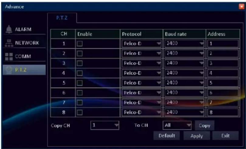
Here you can configure the DVR to be able to operate PTZ devices. PTZ stands for Pan, Tilt & Zoom.
The DVR is compatible with many - but not all - PTZ devices available. For more information, please consult the vendor.
Customize the PTZ camera settings after the PTZ speed dome is properly installed via RS-485 connection.
Enable: Check the channel box which the PTZ camera is connected to.
Protocol: A protocol is like a common language that the DVR uses to communicate to the PTZ device. Make sure this setting matches the requirements of your device.
Baud rate: Check the PTZ camera documentation to get to know this parameter.
Address: Specify the command address of the PTZ camera that you want to associate with the selected channel.
Copy CH/To CH: Copy the current settings to all channels or one specific channel. Click the arrow to select an option and then click Copy.
After all settings are complete, click Apply.

Note:
Do not use motion detection function on the PTZ camera to avoid wrong 'motion' interpretation.
Search
Record Search
The Record Search allows you to search the recordings saved on the storage. The search can be performed based on start time, end time, record type and channel. All recordings that match the search criteria are displayed on the screen.
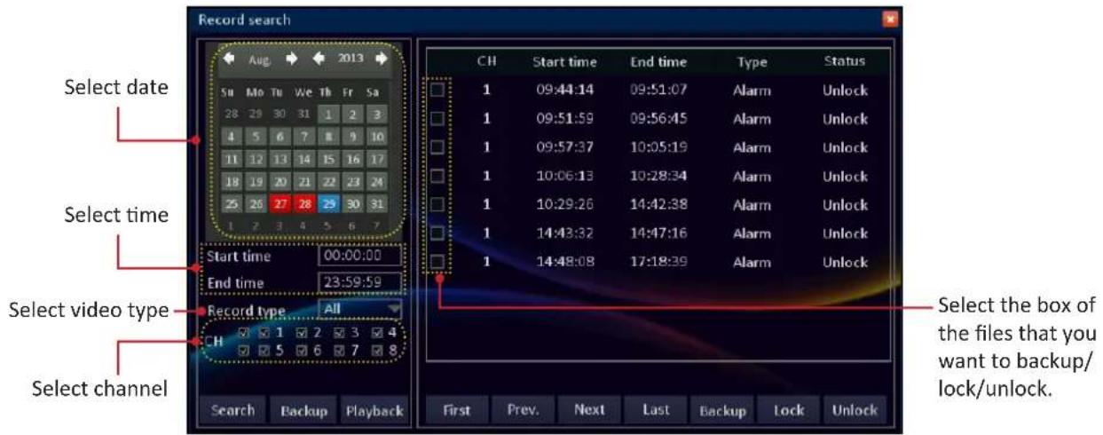
Search: After selecting date, time, video type, and channel, click to search for recorded files. The search results are displayed on the right window.
First/Prev/Next/Last: Click to browse the search result page by page.
Lock: After selecting Unlock recorded files, click to lock the files. The locked files cannot be overwritten.
Unlock: After selecting Lock recorded files, click to unlock the files.
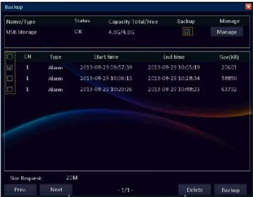
Backing up Videos
To backup files:
- Connect a USB storage device to the USB port on the back of the DVR.
- Perform a Record Search, see "Record Search" on page 58.

Note:
To reduce the video file size, use the "Trimming Videos" on page 58.
After selecting the files that you want to backup, click Backup. A confirmation message appears on the screen. Click Backup to continue. The Backup Status screen appears.
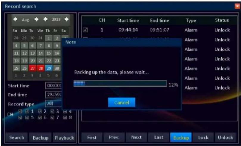
When backup is complete, click OK to close the Backup Status screen.

Note:
- Before backing up the recorded file, be sure to plug a USB device into the USB port of the DVR.
- Do not remove the USB device while file transferring is in progress.
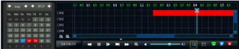
Playing Videos
After selecting date, time, video type, and channel, click Playback to enter the playback mode interface. The selected video file is displayed on the screen. Use the on-screen calendar to make changes to the dates and control bar to control the video playback.
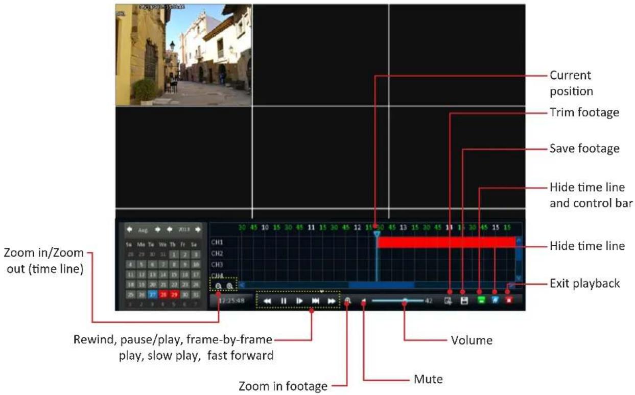
Zoom in/Zoom out (time line): Increase or decrease the time line display.
Rewind: Reverses the footage.
Pause/Play: Pauses the footage or plays the footage at normal speed.
Frame-by-frame play: Press multiple times to play footage fram-by-frame.
Slow play: Plays back footage at reduced speed. Press multiple times to further reduce the speed: 1/2 speed, 1/4 speed, 1/8th speed.
Fast forward: Plays back footage at accelerated speed. Press multiple times to further accelerate the speed: x2 speed, x4 speed, x8 speed.
Zoom in footage: Left mouse click once to view the footage full screen. Then left mouse click on the area on the footage that needs to be enlarged. The area will be enlarged in full screen. Right mouse click to scale down.
Mute: Mute the playback.
Volume: Alters the output volume of playback.
Exit playback: Leaves the playback interface and returns to live viewing mode.
Hide time line: Maximizes the area on-screen for playing back your footage by hiding time line.
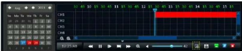
Hide time line and control panel: Maximizes the area on-screen for playing back your footage by hiding time line and control panel.
Trim and Save footage: Used to mark a Start Time and End Time for the selection and save the selection. See "Trimming Videos" on page 62.
Current position: A basic progress meter. You can click to move the current position icon to quickly scan through video events.
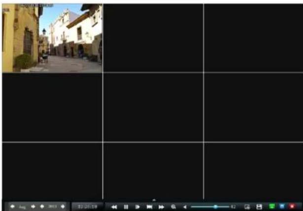
natural_image
Black-and-white photo of a European-style street with buildings and a paved path, no visible text or symbolsPlayback Screen (Hide Time Line)

natural_image
Black-and-white street view of a European-style building with a visible road and adjacent greenery (no text or symbols)Playback Screen (Hide Time Line and Control Bar)
Trimming Videos
To mark the start and end trimming time during playback in full screen, do the following:
- Drag the slider to where you would like to start trimming and click the icon.
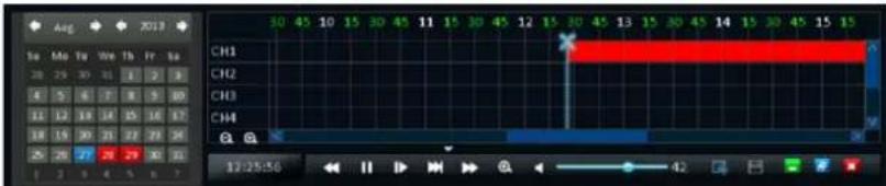
To stop trimming the video clip, click the icon again. The trimmed portion is displayed as white section.
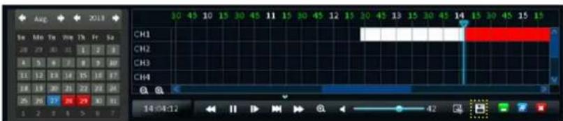
To save the trimmed video, click the icon. Select the file that you want to save and check the Backup box.
Then click Backup to save the file into the selected USB drive.

Note:
- Before backing up the recorded file, be sure to plug a USB device into the USB port of the DVR.
- Do not remove the USB device while file transferring is in progress.
Log Search
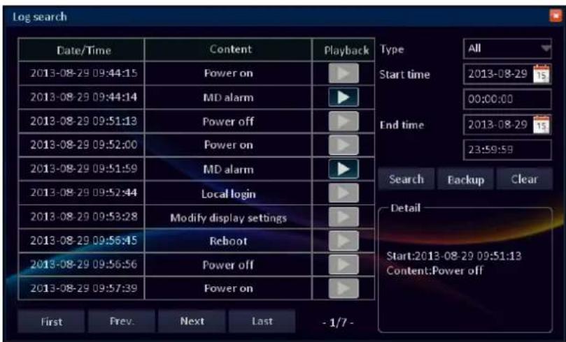
The Log Search displays a list of events, presented in chronological order: the most recent events will be at the end of the list.
The Log will list all events that the DVR monitored.
Type: Select the log type. The available options are: all, alarm, operation. All will include in the result both alarm and operation events.
Start time/End time: Specify the Start Time and End Time to filter the list.
Search: After selecting date, time, and log type, click to search for recorded files. The search results are displayed on the right window.
First/Prev/Next/Last: Click to browse the search result page by page.
Clear: Click to delete the log file. A pop-out message appears, click Yes to confirm file deletion.
Backup: After selecting the log files that you want to backup, click to start file backing up process.
To view the recorded file on the selected date/time, click the playback starts automatically.

Note:
- Before backing up the recorded file, be sure to plug a USB device into the USB port of the DVR.
- The log files are saved in "*.TXT" format.
- Do not remove the USB device while file transferring is in progress.
Disk Management
HDD
Formatting HDD
Displays the HDD connected to the internal SATA port. To make sure that the hard disk drive is properly set, it is important to configure the hard disk drive settings before its initial usage.
Click Format to format the hard disk drive. An "Are you sure that you want to format this drive?" Warning message appears on the screen. Click Yes to proceed.
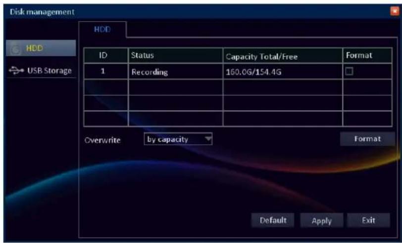
Overwrite: Select an overwrite interval options.
By days: Define the beginning date of the files that will be overwritten.
By capacity: Define the capacity limit when the oldest files will be overwritten.
Never: The recording will stop when the hard disk is full.
After all settings are complete, click Apply.
USB Storage
View and configure the USB storage device, connected to the USB port on back panel.
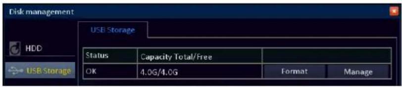
Formatting USB Disk Drive
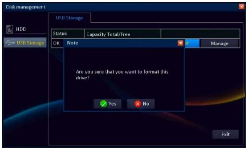
Click Format to format the USB disk drive.
An "Are you sure that you want to format this drive?" Warning message appears on the screen. Click Yes to proceed.

Note:
Do not remove the USB device while drive formatting is in progress.
Managing USB Disk Drive
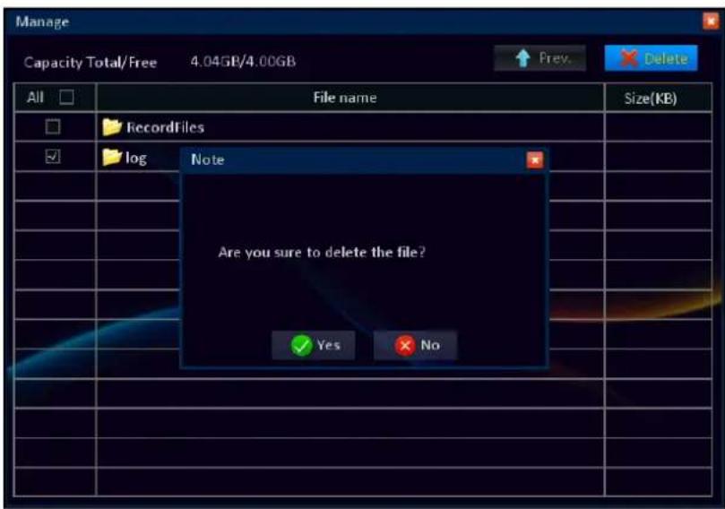
Click Manage to view or delete file(s) stored in the USB disk drive.
To delete folder(s)/file(s), check the respective box(es) and click Delete. An "Are you sure that you want to delete the file?" Warning message appears on the screen. Click Yes to proceed.
Note:
Do not remove the USB device while file deletion is in progress.
eSATA (16-channel DVR only)
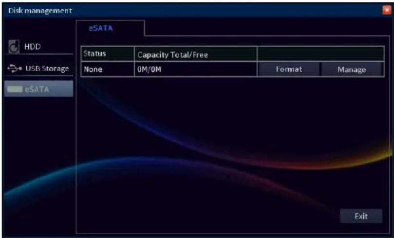
Use eSATA connection for backup purposes.
Note:
The eSATA disk drive cannot be used for direct recording.
Format: Click to format the external hard disk drive.
An "Are you sure that you want to format this drive?" Warning message appears on the screen. Click Yes to proceed.

Note:
Do not remove the external HDD while drive formatting is in progress.
Manage: Click to view or delete file(s) stored in the external hard disk drive.
Information
Device
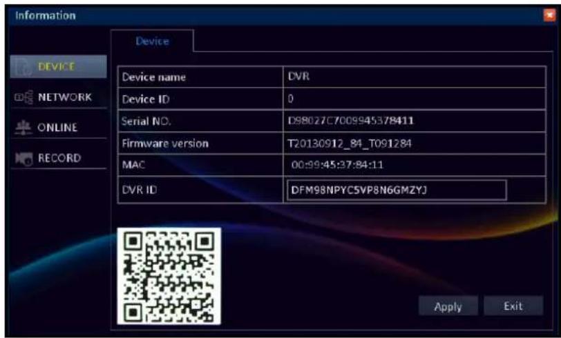
Display the DVR information including the device name and ID, serial number, firmware version, MAC address, and DVR ID.
The device information is mainly used by the technical support, in the event that you require assistance.

Note:
The DVR ID represents the QR code sticker shown on the DVR.
Click Exit to close the current screen.
Network
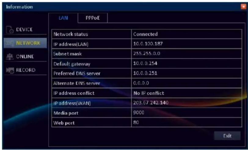
Display the network information including the network status, IP address, subnet mask, default gateway, and other network related information.
Click the PPPoE tab to view the PPPoE network configuration settings.
Click Exit to close the current screen.
Online
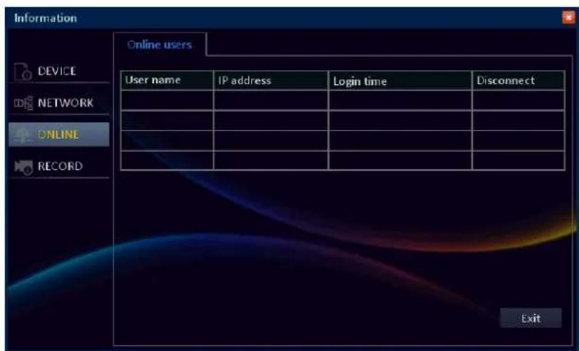
Display the online user name, IP address, log in time, and connection status.
Click Exit to close the current screen.
Record
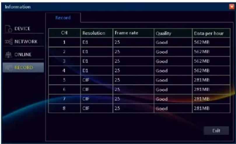
Display the specific channel recording settings including video resolution, frame rate, quality, and recording capacity (per hour).
Click Exit to close the current screen.
Maintenance
Basic
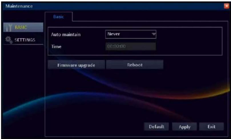
Configure the automatic system maintenance, update the firmware settings, or reboot the DVR manually.
After all settings are complete, click Apply.
Manual Reboot
Click Reboot to reboot the DVR. A message appears, click Yes to confirm the operation.
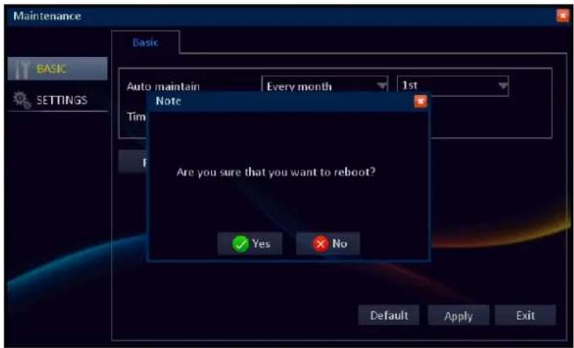
Set Auto Maintenance
To maintain the operational integrity of the DVR, it is recommended to reboot your DVR periodically. Similarly to the PC that becomes unstable if left on for a very long time, the DVR may become unstable if not rebooted periodically. We suggest to reboot the DVR every day.
To ease to perform periodical reboots, you can Set Auto Maintenance to automatically reboot the DVR on a specified schedule. When the DVR reboots, all settings and data are refreshed from the memory, which optimizes the DVR performance.
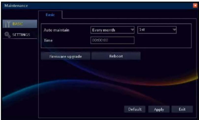
In Auto maintain, select the frequency to reboot the DVR. Options are:
- Every month: Reboots the DVR on a monthly basis. If this option is selected, specify the date (1 to 31) and the time to reboot the DVR.
- Every week: Reboots the DVR on a weekly basis. If this option is selected, specify the day of the week and the time to reboot the DVR.
- Every day: Reboots the DVR on a daily basis. If this option is selected, specify the time you want to reboot the DVR.

Note:
The illustration above is an example of Auto maintain set to Every month. The available fields vary depending on the selected Reboot option.
After all settings are complete, click Apply.
Click Exit to close the current screen.
Update System Firmware
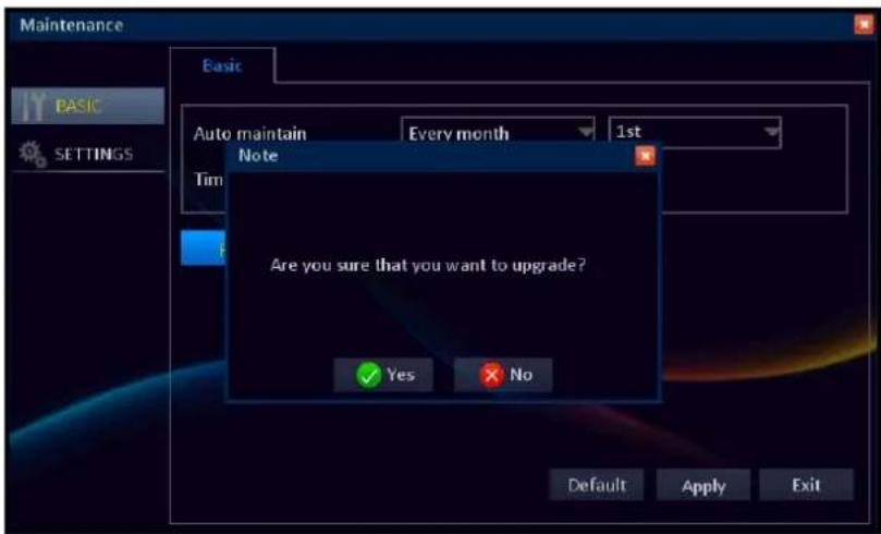
Use this feature to update the firmware with the latest version.
Download the firmware folder named "dvrupgrade" and save the folder in a USB flash drive. Insert the USB flash drive into a USB port of the DVR and click Firmware upgrade to update the firmware.
A message appears, click Yes to confirm the operation.
Warning:
Do not turn off the power or unplug from the power supply while updating.

Note:
After the updating firmware process is complete, it is highly recommended to restore the default settings (see "Load Default Settings" on page 66) and then reboot the system.
Settings
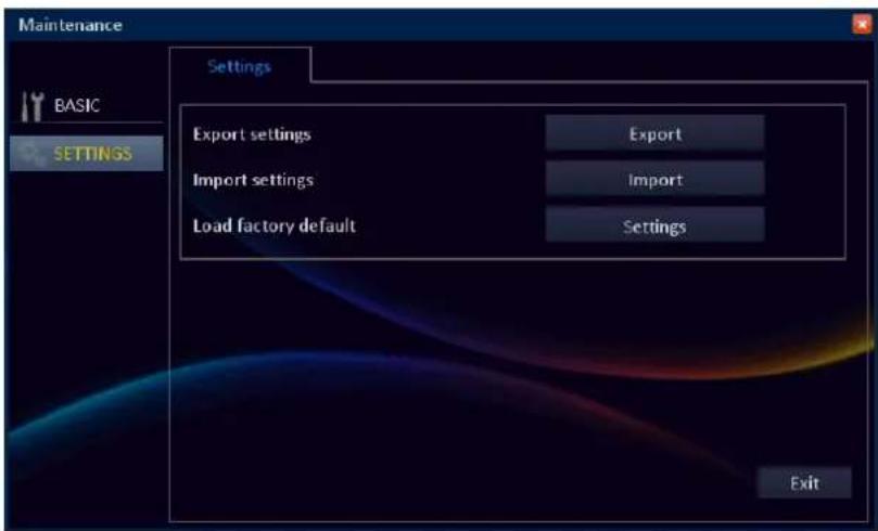
Use this feature to save the current DVR settings, import the configured settings stored in the USB flash drive, or load the system default settings.

Note:
- Before saving/importing the settings, be sure to plug a USB device into the USB port of the DVR.
- The settings file is less than 50KB.
In Export settings, click Export to save the current DVR settings on a USB storage.
In Import settings, click Import to import the DVR settings
When data exporting/importing is complete, click OK to close the current screen.

Note:
Do not remove the USB device while file transferring is in progress.
Click Exit to close the current screen.
Load Default Settings
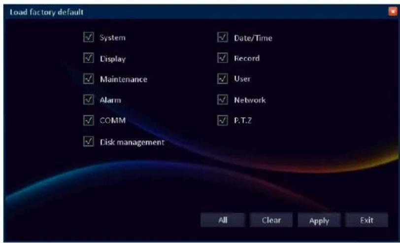
Use this feature to restore the factory default settings of the DVR.
In Load factory default settings, click Settings to load the default settings.
Check the respective setting option box that you want to restore.
« TIP »
- To restore all settings, click All.
• To deselect all checked boxes, click Clear.
After all settings are complete, click Apply.
Logout
Click log out of the system. A message appears, click Yes to confirm the operation.
The Main menu will be locked after you log out. You need to enter the user name and password before entering the Main menu.
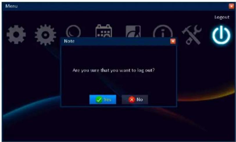
Web Client
Use Web Client to remotely access the DVR at anytime.
Before accessing Web Client for first time:
- Ensure that the Network settings of the DVR is properly configured. See "LAN" on page 49.
- Your computer has a web browser, such as Internet Explorer or Safari, installed.
- UPnP is configured in the DVR and Router, or the port forwarding is completed in the Router.
PC login
Open your computer web browser and enter the DVR IP address or domain name in the URL box.

Don't know the IP Address of your DVR?
The IP address of the DVR vary depending on the network settings you configured in NETWORK menu (see "LAN" on page 49).
- If your network type is DHCP, ask your network administrator for the IP address assigned to the DVR.
- If your network type is PPPoE, ask your Internet Service Provider (ISP) for the IP address assigned to the DVR.
- If your network type is Static IP, check the IP address you configured for IP address in LAN menu.
- If the DVR is connected to a DDNS, check the Domain Name that you configured when you created the DDNS account and type the domain name in the URL box.
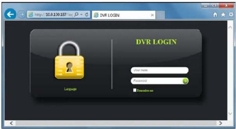
Then enter the login name and password. Click to login.

Note:
The default DVR user name and password are:
User name: admin
Password: 123456
Interface Overview
After you login to Web Client, the Live screen appears.

Note:
The number of channels displayed may vary depending on the DVR model. The illustration below is from a 8-channel DVR.
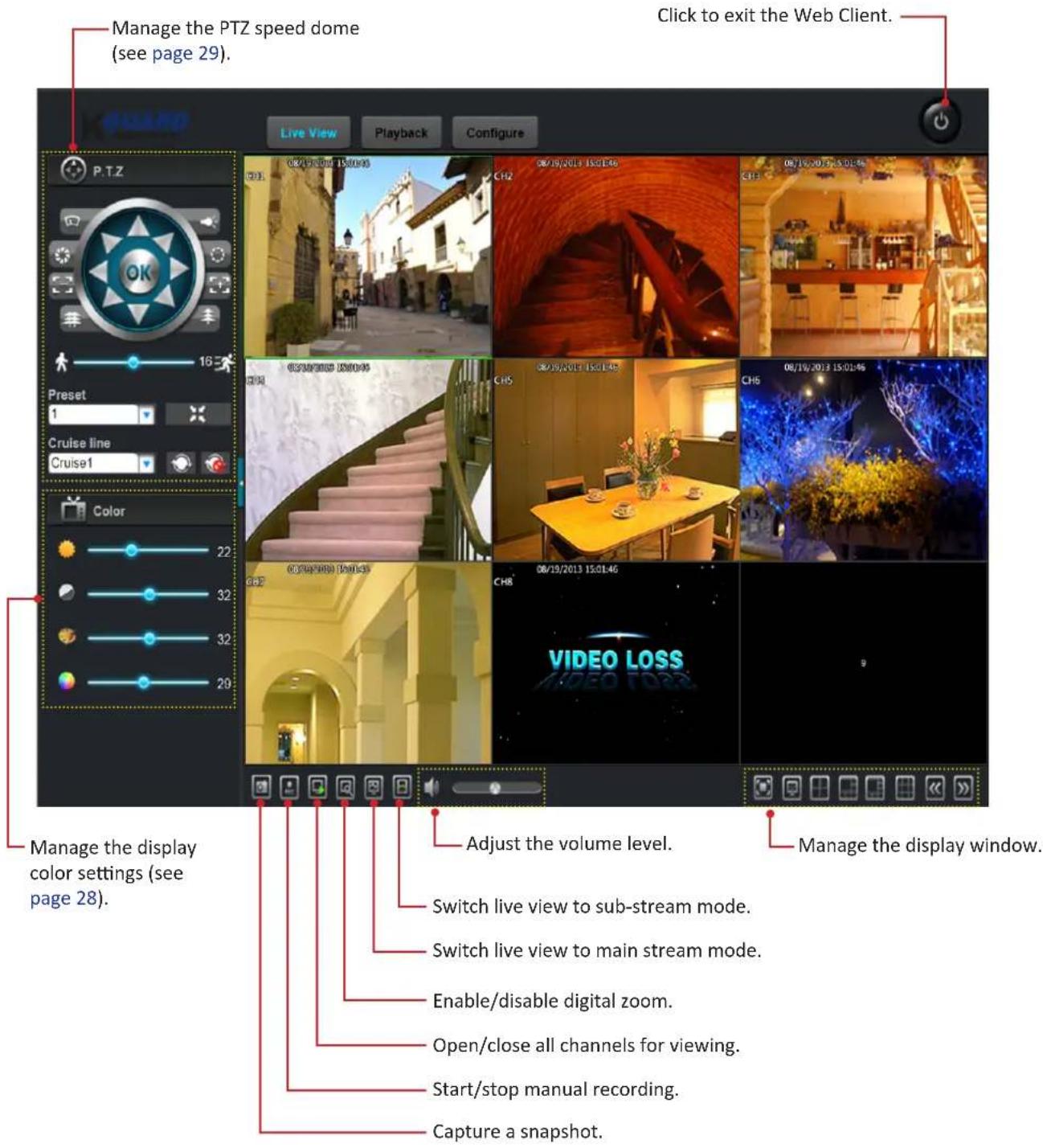
Switching Screen Modes
The Live screen can be viewed in different modes. Click the respective icon on the task bar to switch to different display mode.
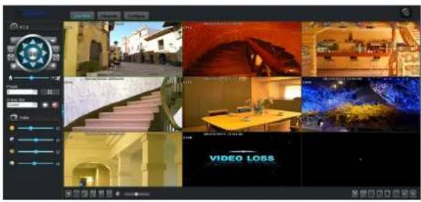
Click to switch to Full Window mode.
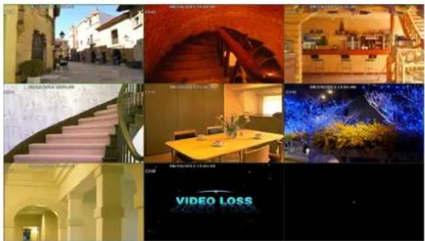
Click ☐ to switch to Full Screen (panel control is hidden) mode.
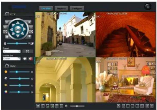
Click ☐ to switch to 4-split Window mode.
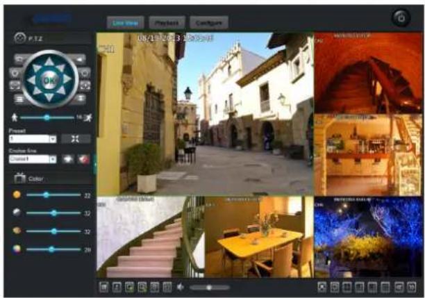
Click ☐ to switch to 6-split Window mode.
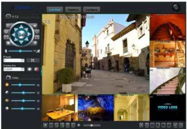
Click to switch to 8-split Window mode.
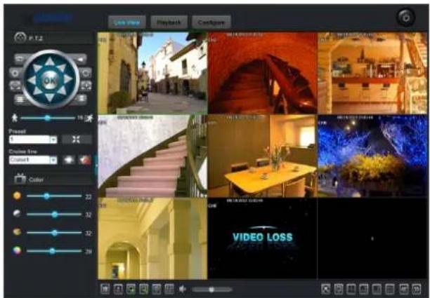
Click ☐ to switch to 9-split Window mode.
Video Playback
Click Playback tab remotely search, play, and download recorded videos.
Searching and Playing Videos
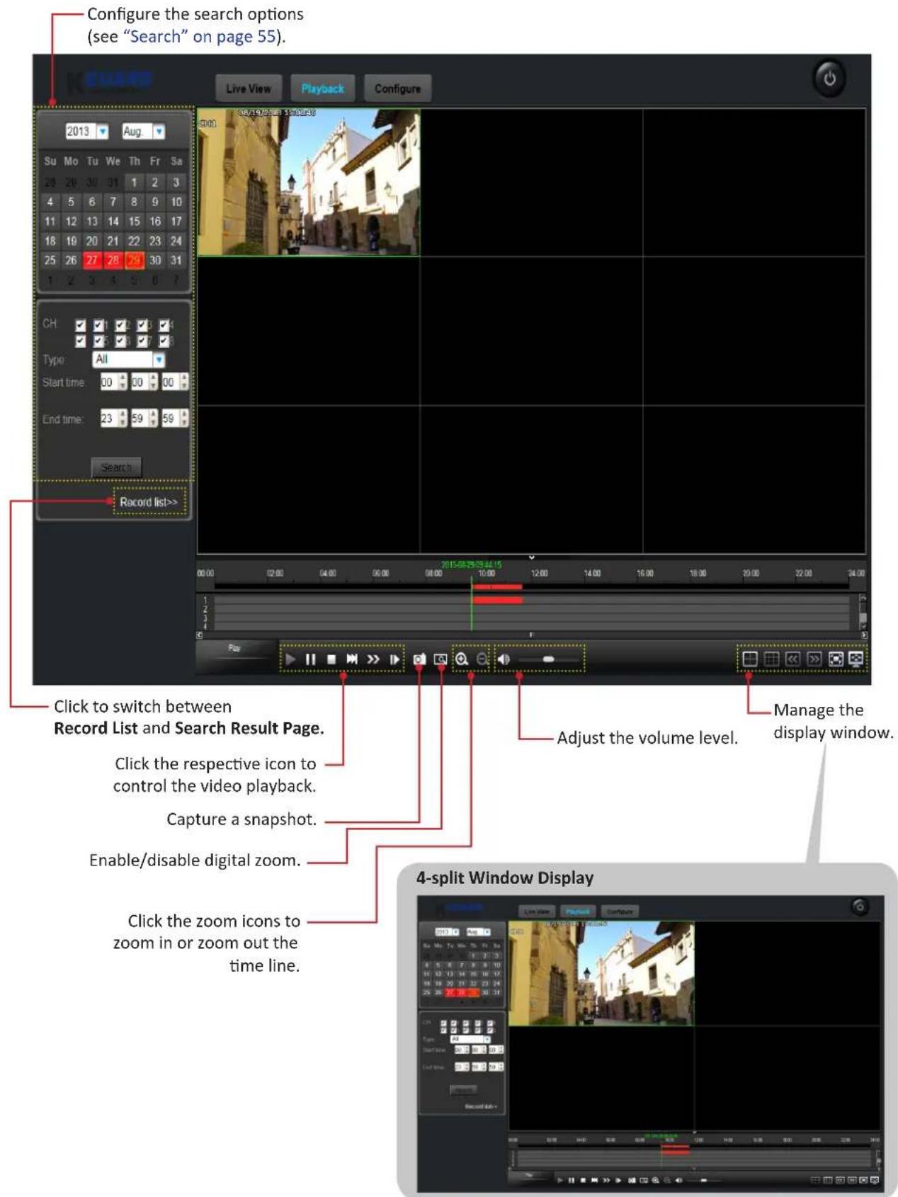
Downloading Recorded Videos
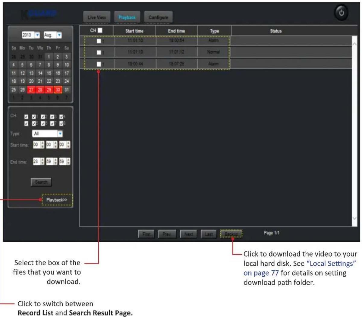
Configure Settings
Click Configure tab to remotely configure the DVR.
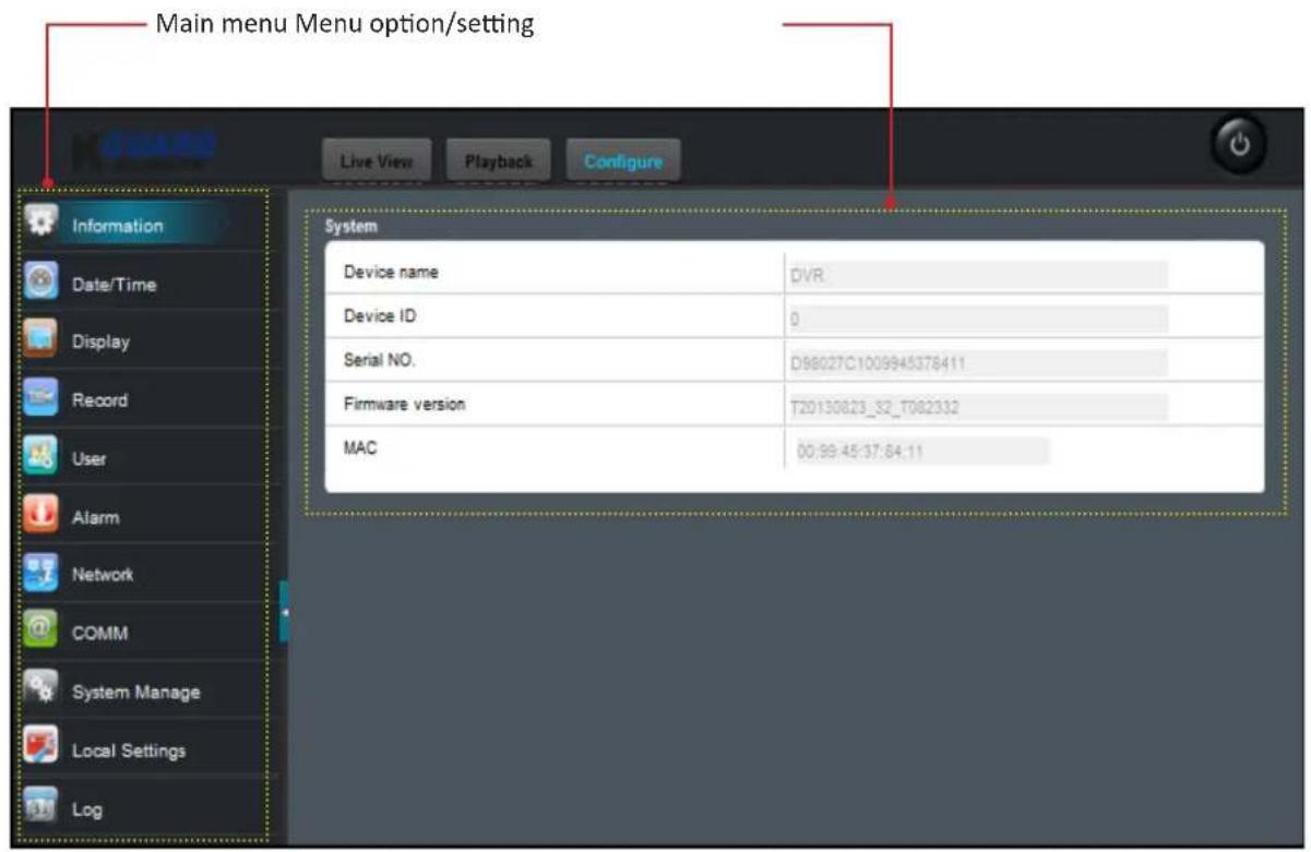
The available menu options and setting configurations are very similar to the DVR system menu.

Note:
The relevant page reference for additional information is listed on each menu item.
Information
View the DVR information including the device name and ID, serial number, firmware version, and MAC address.
| Device name | DVR |
| Device ID | 0 |
| Serial NO. | D98027C1009945378411 |
| Firmware version | T20130823_32_T082332 |
| MAC | 00:99:45:37:84:11 |
Date/Time
Configure the date, time, and daylight saving time settings.
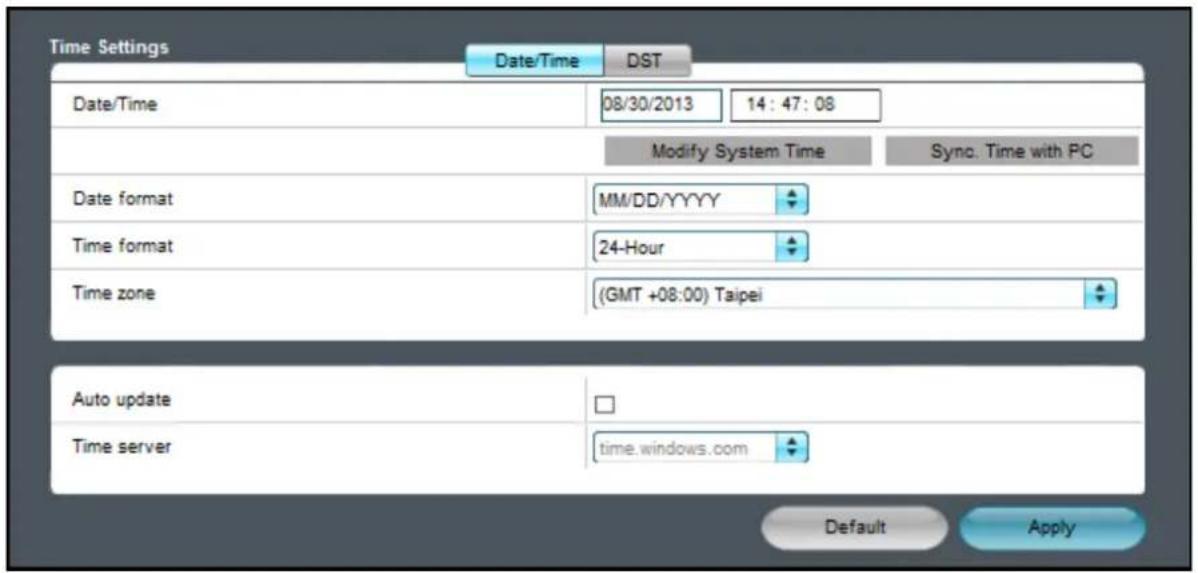
- Select the Date/Time tab to configure the date and time settings. Refer to "Date/Time" on page 33.
- Select the DST tab to configure the daylight saving time settings.
Refer to "DST (Daylight Saving Time)" on page 34.
Display
Customize how channels are displayed on the monitor screen.
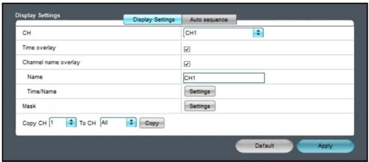
- Select the Display Settings tab to configure the display settings. Refer to "Display" on page 34.
- Select the Auto sequence tab to configure the order of how the channels appear when auto sequence function is activated. Refer to "Auto Sequence" on page 36.
Record
Customize the recording settings and schedule. Refer to "Record Setup" on page 38.
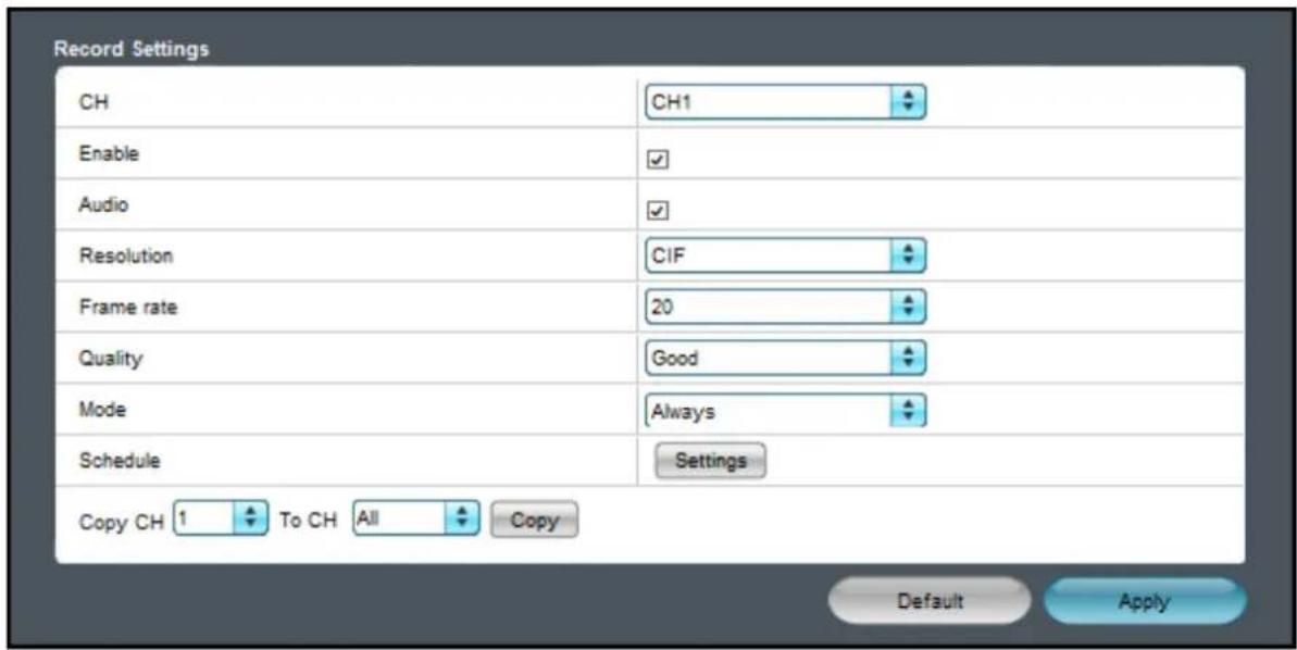
User
Change the password and authorize users and set the access rights in using the DVR.
Refer to "User Setup" on page 40.
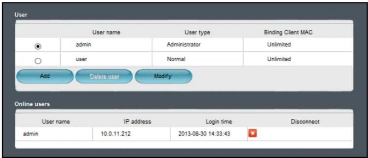
Alarm
Customize the motion, sensor, video loss, and other event(s) recording settings.
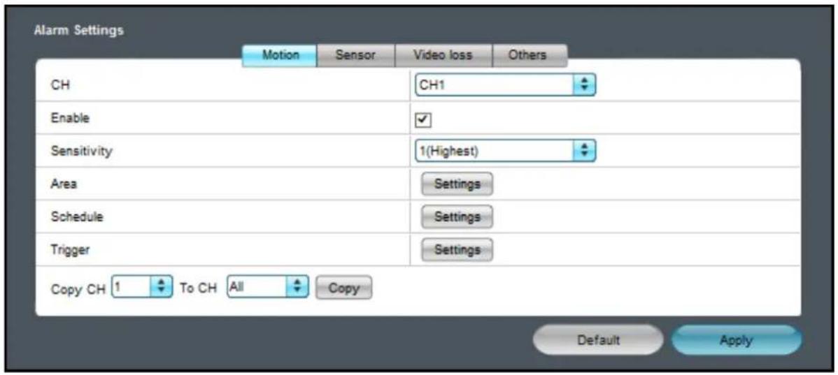
- Select the Motion tab to customize the motion recording settings. Refer to "Motion" on page 42.
- Select the Sensor tab to customize the sensor alarm settings. Refer to "Sensor" on page 45.
- Select the Video loss tab to customize the video loss alarm settings. Refer to "Video Loss" on page 47.
- Select the Others tab to customize the event(s) alarm settings. Refer to "Others" on page 48.
Network
Configure the basic network settings.
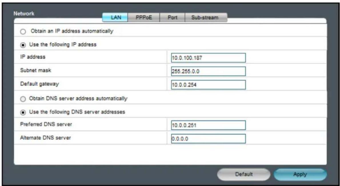
- Select the LAN tab to configure the basic network settings. Refer to "LAN" on page 49.
- Select the PPPoE tab to Configure the basic network settings using PPPoE. Refer to "PPPoE" on page 50.
- Select the Port tab to specify the Client Port and HTTP Port numbers. Refer to "Port" on page 50.
- Select the Sub-stream tab to customize the video stream settings of a particular channel if the channel is being viewed via remote access. Refer to "Sub-stream" on page 51.
COMM
Configure Internet related application settings.

Note:
Be sure that the DVR network connection is properly configured before proceeding with the following setup.
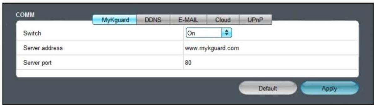
- Select the MyKguard tab to enable remote access the DVR via MyKguard. Refer to "MyKguard" on page 51.
- Select the DDNS tab to configure the domain server settings. Refer to "DDNS" on page 52.
- Select the E-MAIL tab to configure the email setup. Refer to "E-mail" on page 52.
- Select the Cloud tab to configure the cloud storage settings. Refer to "Cloud" on page 54.
- Select the UPnP tab to activate the UPnP function. Refer to "UPnP" on page 53.
System Manage
Configure the DVR general settings including disk management, PTZ speed dome, system, maintenance options, and other related settings.
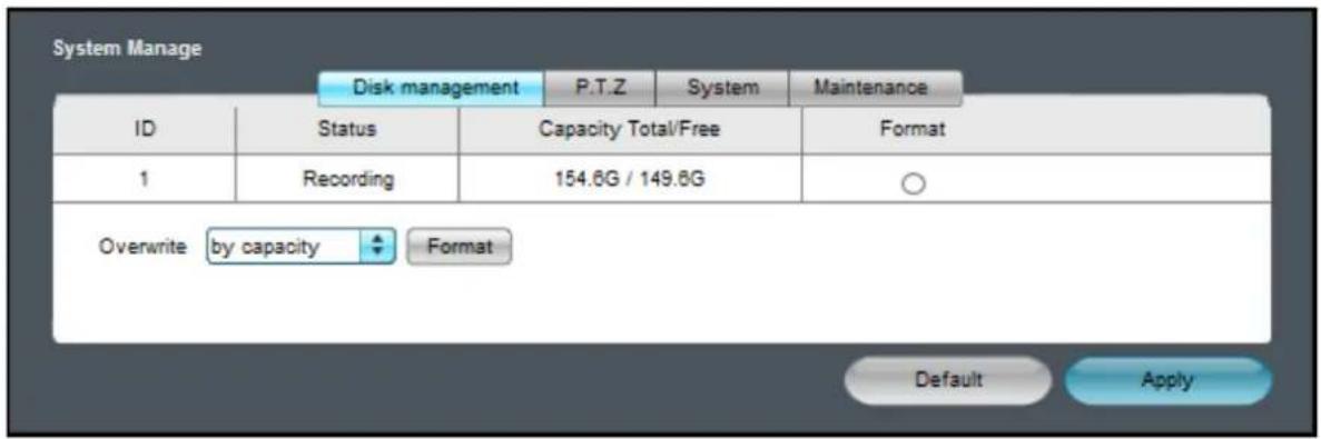
- Select the Disk management tab to configure the hard disk drive. Refer to "HDD" on page 60.
- Select the P.T.Z tab to customize the PTZ camera settings. Refer to "PTZ Setup" on page 55.
- Select the System tab to configure the DVR name, device ID, and video format.
Refer to "System Setup" on page 33. - Select the Maintenance tab to configure the automatic system maintenance, load factory defaults, update the firmware settings, or reboot the DVR manually. Refer to "Maintenance" on page 63.
Local Settings
Specify the local path directory to save downloaded videos, files, and snapshots.
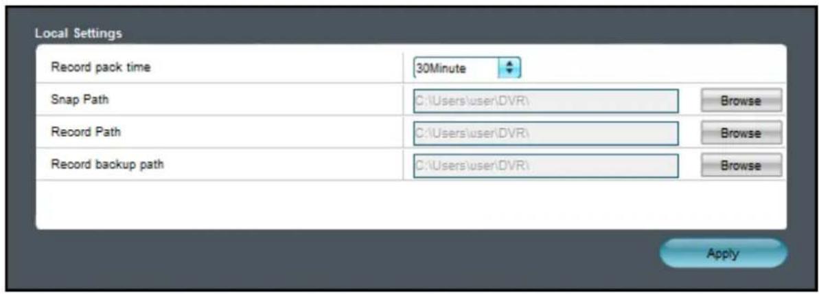
Set the recording length for each video file (5/10/15/30 minutes) and click the corresponding Browse button to modify the path.
Click Apply to save the settings.
Log
Search and backup the log. Refer to "Log Search" on page 59.
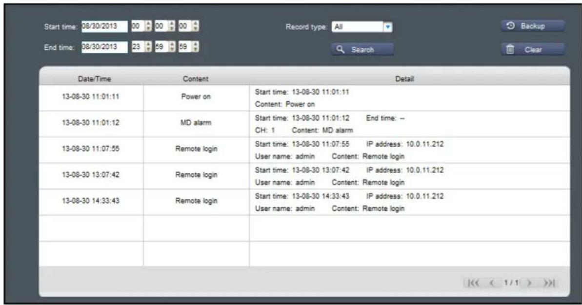
Appendix
Troubleshooting
If you experience any problems in using the DVR, try the following solutions to these common problems before calling for service. If problems persist, contact the customer service in your area.
Question: The DVR does not turn on and the indicators are not lit.
Answer:
- Check if the power adapter is properly connected.
- Plug the power cord to another power outlet, the current outlet may be damaged.
- The power cord may be damaged, contact the dealer to purchase a new one.
Question: Some channels have no video signal.
Answer:
- Check if the camera is properly connected.
- Check if the camera is supplied with power.
- Set the correct video format used in your country (NTSC/PAL). See "System Setup" on page 33.
- The camera cable may be damaged, replace with a new one.
Question: I have changed the administrator password but I cannot remember it.
Answer:
- To obtain the factory default password, contact your retailer or directly send an email to KGUARD at support@kguardsecurity.com.
Question: The remote control is not working.
Answer:
- Make sure nothing is blocking the remote control and the DVR sensor. Aim the remote control at a proper distance.
- Check the remote control batteries.
Question: I cannot control the PTZ camera.
Answer:
- Make sure the protocol, baud rate, address code and other settings on the camera match the settings you have configured on the DVR. See "PTZ Setup" on page 55.
- Check if the cables are properly connected.
Question: I am getting too many email alerts.
Answer:
- Check if the Sending Interval setting for the email alerts. See "E-mail" on page 52.
- If the DVR keep reporting errors such as Video Loss or HDD error, check if the camera is properly connected or other hardware configurations.
Question: I cannot access the web client.
Answer:
- Check if the network cable is properly connected to the DVR.
- Check if the network settings are properly configured. See "LAN" on page 49.
- Ensure that you have Internet Explorer 6 or above.
Question: The buzzer keeps on sounding.
Answer:
- Check the alarm settings. Motion Detection or Video Loss may be detected. Check the HDD capacity and the video connections, which may be triggering the alarm.
Specifications
| Model AR421 AR821 AR1621 | |||||
| No. of Channel 4 Channels 8 Channels 16 Channels | |||||
| Cloud | |||||
| Cloud Storage Yes | |||||
| Storage Mode Schedule / Motion Detection | |||||
| Video | |||||
| Video Format NTSC or PAL | |||||
| Video Input 4 BNC Inputs 8 BNC | Inputs 16 BNC Inputs | ||||
| Video Output | 1 VGA, 1 BNC, 1 HDMI Outputs | ||||
| Video Output Resolution 1024x768, 1280x1024, 1366x768, 1440x900, 720p, 1080p | |||||
| Audio | |||||
| Audio Input 4 RCA Inputs | 8 RCA Inputs | 2 RCA Inputs | |||
| Audio Output | 1 RCA Output | ||||
| Recording | |||||
| Video Compression | H.264 | ||||
| Frame Rate | DI | NTSC | 120fps@CIF (352x240),120fps@HD1 (704x240),120fps@D1 (704x480) | 240fps@CIF (360x240),240fps@HD1 (720x240),240fps@D1 (720x480) | 480fps@CIF (360x240),240fps@HD1 (720x240),240fps@D1 (720x480) |
| PAL | 100fps@CIF (352x288),100fps@HD1 (704x288),100fps@D1 (704x576) | 200fps@CIF (360x288),200fps@HD1 (720x288),200fps@D1 (720x576) | 400fps@CIF (360x288),192fps@HD1 (720x288),192fps@D1 (720x576) | ||
| 960H | NTSC | 120fps@WCIF (480x240),120fps@WHD1 (960x240),120fps@WD1 (960x480) | 240fps@WCIF (480x240),88fps@WHD1 (960x240),88fps@WD1 (960x480) | 480fps@WCIF (480x240),176fps@WHD1 (960x240),176fps@WD1 (960x480) | |
| PAL | 100fps@WCIF (480x288),100fps@WHD1 (960x288),100fps@WD1 (960x576) | 200fps@WCIF (480x288),72fps@WHD1 (960x288),72fps@WD1 (960x576) | 400fps@WCIF (480x288),144fps@WHD1 (960x288),144fps@WD1 (960x576) | ||
| Recording Mode | Always / Manual / Motion Detection / Schedule / Alarm | ||||
| HDD Interface | 1 SATA | ||||
| HDD Support | Up to 2TB | ||||
| Network | |||||
| Plug & Play | Yes | ||||
| Network Interface | RJ45, 10M/100M | ||||
| Network Function | DHCP, PPPoE, Static IP | ||||
| Playback | |||||
| Local Playback | Max. 4 ChannelsSimultaneously | Max. 8 ChannelsSimultaneously | Max. 16 ChannelsSimultaneously | ||
| Playback Search | Time / Channel / Event | ||||
| Playback Mode | Play, Fast Forward, Fast Rewind, Slow Motion, Zoom | ||||
| General | |||||
| PTZ Control | RS485 Built-In, supports PELCO-P & PELCO-D | ||||
| E-SATA Port | No | Yes | |||
| Sensor IN & Alarm OUT Port | 4-IN, 1-OUT | 8-IN, 1-OUT | 4-IN, 1-OUT | ||
Aurora Series: Appendix
| Model AR421 AR821 AR1621 | ||
| Backup Method HDD, USB, Network | ||
| Power Supply 12V/2A | ||
| Operating Temperature (without HDD) | -10°C to 55°C (14°F to 131°F) | |
| Storage Temperature -20°C to 70°C (-4°F to 158°F) | ||
| Working Humidity 10% ~ 90% | ||
| Dimension (W x D x H) 315 x 230 x 40 mm | ||
* Specifications are subject to change without notice.
KGUARD® SECURITY
Copyright © 2013
All rights reserved
Customer Support
KGUARD INFORMATION CO., LTD.
Address: 4F, No.113, Jian 2nd Road,
Jhonghe District, New Taipei City 23585, Taiwan
TEL: +886-2-8228-6080
FAX: +886-2-8221-6857
Email: support@kguardsecurity.com
USA Technical Support Contact
TEL:1-949-450-0052
Email: support@kworldcomputer.com