Cerberus P6331-5 - Router Pentagram - Free user manual and instructions
Find the device manual for free Cerberus P6331-5 Pentagram in PDF.


| Product Type | Wireless Router |
| Brand | Pentagram |
| Model | Cerberus P6331-5 |
| Dimensions (approx.) | 200 x 150 x 30 mm |
| Weight (approx.) | 300 g |
| Power Input | 12V DC, 1A |
| Wi-Fi Standard | IEEE 802.11ac (Wi-Fi 5) |
| Wi-Fi Speed | Up to 1200 Mbps (dual-band) |
| LAN Ports | 4 x Gigabit Ethernet |
| WAN Port | 1 x Gigabit Ethernet |
| Antennas | 4 external detachable |
| Security | WPA2, WPA3, SPI Firewall |
| Additional Features | QoS, Parental Controls, Guest Network |
| Care Instructions | Keep in well-ventilated area, clean with dry cloth |
| Operating Temperature | 0 to 40°C |
| Humidity | 10% to 90% non-condensing |
Frequently Asked Questions - Cerberus P6331-5 Pentagram
User questions about Cerberus P6331-5 Pentagram
0 question about this device. Answer the ones you know or ask your own.
Ask a new question about this device
Download the instructions for your Router in PDF format for free! Find your manual Cerberus P6331-5 - Pentagram and take your electronic device back in hand. On this page are published all the documents necessary for the use of your device. Cerberus P6331-5 by Pentagram.
USER MANUAL Cerberus P6331-5 Pentagram
Installation and User's Manual
PENTAGRAM Cerberus
ADSL2+ Wi-Fi
(P 6331-5)

PENTAGRAM
THE PERFECT SIMPLICITY
The latest versions of manual, drivers and applications are available on
www.pentagram.eu
NOTE! Any information and technical data are subject to change without prior notification and/or indication in this manual.
INDEX
INTRODUCTION 5
FEATURES....5
PACKAGE CONTENTS....6
PRODUCT OVERVIEW 7
IMPORTANT NOTES 7
FRONT PANEL 7
BACK PANEL....8
DEFAULT SETTINGS 8
RESETTING ROUTER....9
CONNECTING CERBERUS TO COMPUTER....9
CONFIGURE TCP/IP 9
CONFIGURE ROUTER VIA WEB BROWSER.... 14
LOGIN 14
NAVIGATION.... 15
SETUP TAB....17
BASIC TAB 20
ADVANCED TAB 24
WIRELESS TAB....56
SECURITY TAB....63
STATUS TAB....66
HELP TAB 72
TROUBLESHOOTING 73
USING LEDS TO DIAGNOSE PROBLEMS.... 73
PROBLEMS WITH THE WEB INTERFACE.... 73
PROBLEMS WITH THE LOGIN USERNAME AND PASSWORD.... 74
PROBLEMS WITH LAN INTERFACE 74
PROBLEMS WITH WAN INTERFACE 74
PROBLEMS WITH THE INTERNET ACCESS.... 75
Introduction
Thank you for purchasing the Cerberus ADSL2+ Wi-Fi ADSL2+ Modem/Router by PENTAGRAM. Your new router is an all-in-one unit that combines an ADSL modem, ADSL router, Ethernet network switch and wireless Access Point to provide everything you need to get the machines on your network connected to the Internet over an ADSL broadband connection.
The Cerberus ADSL2+ Wi-Fi router complies with ADSL2+ standards for deployment worldwide and supports downstream rates of up to 24 Mbps and upstream rates of up to 1 Mbps. Designed for small office, home office and residential users, the router enables even faster Internet connections. You can enjoy ADSL services and broadband multimedia applications such as interactive gaming, video streaming and real-time audio much easier and faster than ever before.
Features
- A 4-port 10/100Mbps fast Ethernet switch is built-in with automatic switching between MDI and MDI-X for 10Base-T and 100Base-TX ports, with auto detection allowing you to use either straight or cross-over Ethernet cables.
- With built-in 802.11g access point for extending the communication media to WLAN while providing the WEP and WPA/WPA-TKIP/PSK for securing your wireless networks.
- Network Address Translation (NAT) allows multiple users to access outside resources such as the Internet simultaneously with one IP address/one Internet access account. Many application layer gateways (ALG) are supported such as web browser, ICQ, FTP, Telnet, E-mail, News, Net2phone, Ping, NetMeeting, IP phone and others.
- Universal Plug and Play (UPnP) and UPnP NAT Traversal: This protocol is used to enable simple and robust connectivity among stand-alone devices and PCs from many different vendors, and it makes setting up a network simple and affordable. UPnP architecture leverages TCP/IP and the Web to enable proximity networking in addition to control and data transfer among networked devices. With this feature enabled, you can seamlessly connect to Net Meeting or MSN Messenger.
- The Dynamic DNS service allows you to alias a dynamic IP address to a static hostname. This dynamic IP address is the WAN IP address. To use the service, you must first apply for an account from a DDNS service such as http://www.dyndns.org.
- The Cerberus ADSL2+ Wi-Fi provides an embedded PPPoE client function to establish a connection. You get greater access speed without changing the operation concept, while sharing the same ISP account and paying for one access account. No PPPoE client software is required for the local computer. Automatic Reconnect and Disconnect Timeout (Idle Timer) functions are also provided.
-
Virtual Server: You can specify which services are visible to outside users. The router detects an incoming service request and forwards it to the specific local computer for handling. For example, you can assign a PC in a LAN to act as a Web server inside and expose it to the outside network. Outside users can browse inside the web server directly while it is protected by NAT. A DMZ host setting is also provided for local computers exposed to the outside Internet network.
-
Dynamic Host Configuration Protocol (DHCP) Client and Server: On a WAN site, the DHCP client obtains an IP address from the Internet Service Provider (ISP) automatically. On a LAN site, the DHCP server allocates a range of client IP addresses, including subnet masks and DNS IP addresses and distributes them to local computers. This provides an easy way to manage the local IP network.
- Static and RIP1/2 Routing: An easy static routing table or RIP1/2 routing protocol supports routing capability.
- SNMP (Simple Network Management Protocol): SNMP allows convenient remote management of the router.
- Web-based GUI: A web-based GUI offers easy configuration and management. User-friendly and with on-line help, it also supports remote management capability for remote users to configure and manage this product.
- Firmware Upgradeable: You can upgrade the router with the latest firmware through its web-based GUI.
- High Speed Internet Access: downstream rates of up to 24Mbps and upstream rates of up to 1Mbps. Cerberus ADSL2+ Wi-Fi is compliant with the following standards:
ANSI T1.413 issue 2,
ITU-T G.992.1 (G.dmt),
ITU-T G.992.2 (G.lite),
ITU-T G.992.3 (ADSL2 G.dmt.bis),
ITU-T G.992.5 (ADSL2+),
Reach Extended ADSL (RE ADSL). - Multi-Protocol to Establish a Connection: The router supports following protocols to establish a connection with an ISP:
PPPoA (PPP over ATM Adaptation Layer 5 – RFC 2364),
PPPoE (PPP over Ethernet – RFC 2516)
RFC 1483/2684 encapsulation over ATM (bridged or routed),
CLIP (RFC 2225, previously IPoA – RFC 1577)
The router also supports VC-based and LLC-based multiplexing.
Package Contents
- PENTAGRAM Cerberus ADSL2+ Wi-Fi
- Power adapter 9 V, 1 A
- Ethernet cable (RJ-45)
- Telephone cable (RJ-11)
- CD
- Quick Installation Guide
Product Overview
Important Notes

- Do not use the router in high humidity or high temperatures.
- Do not use the same power source for the router as other equipment.
- Do not open or repair the case yourself. If the router is too hot, turn off the power immediately and have it repaired at a qualified service center.
- Avoid using this product and all accessories outdoors.
- Place the router on a stable surface.
- Only use the power adapter that comes with the package. Using a different voltage rating power adaptor may damage the router.

Front Panel

| LED Action Description | ||
| POWER Off | No power is supplied to the device | |
| Steady | light Connected to an AC power supply | |
| ETHERNET Off | No Ethernet connection | |
| Steady | light Connected to an Ethernet port | |
| Blinking | Light Transmitting/Receiving data | |
| WIRELESS Off | Access point is disabled | |
| Steady | light Access point is enabled | |
| Blinking | Light Transmitting/Receiving data | |
| ADSL Off | No ADSL signal | |
| Steady | light ADSL signal is established | |
| Blinking | Light Establishing ADSL signal | |
| INTERNET | Off No internet connection | |
| Steady | light Connected to the Internet | |
| Blinking | Light Transmitting/Receiving data | |
Back Panel

Label Used for...
ADSL (RJ-11) Connecting the telephone cable
ETHERNET 1-4 (RJ-45) Connecting with computers/devices through Ethernet cable
RESET Resetting the device. Press for 10 seconds to reset
9V DC Connecting with supplied power adapter (9V 1A)
ON/OFF Switching the device on/off
Default Settings
Before changing configuration familiarize yourself with these default settings.
| IP Address 192.168.1.1 | |
| Subnet Mask 255.255.255.0 | |
| SSID yournetworkname | |
| DHCP Server Enabled | |
| DHCP Server IP Address Pool | 253 IP addresses from 192.168.1.2 |
| IP Address Lease Time 3600 seconds (1 hour) | |
| User Name admin | |
| Password admin | |
It is recommended to set username and password as soon as possible.
If you ever forget the password to log in, you may need to reset router to restore the factory default settings. This procedure is described on the next page.
Resetting router
- Turn router on and wait about 2 minutes for router initialization.
- Press and hold RESET button on the back panel of router for 10 seconds.
Connecting Cerberus to Computer.
Cerberus can be connected to computer via Ethernet or WLAN:
Connecting via Ethernet Port (Ethernet Card)
If there is an available LAN card present on your PC, you just simply connect ADSL router and PC through the Ethernet cable. Once you establish Internet connection, you could browse the Web through the Ethernet cable.
Connecting via WLAN Interface (Wireless Card)
To connect PC to Cerberus via WLAN, Wireless Adapter must be properly installed and configured and both router and PC must be in the same subnet.
Configure TCP/IP
This part will help you to configure your computer to communicate with Cerberus ADSL2+ Wi-Fi router properly. Computer must be either equipped with network adapter connected directly to ADSL2+ Wi-Fi router or wireless network adapter (compatible with Wi-Fi 802.11b/g standard). Wireless network adapter must have the same session ID (ESSID) and establish connection with the network created by router. You can also connect to ADSL2+ Wi-Fi router via network hub/switch. Default IP address of the router is 192.168.1.1 and subnet mask is 255.255.255.0. Fastest and easiest method to configure your computer is to obtain an IP address automatically from router's DHCP server.
Make sure that TCP/IP protocol and network adapter are installed on your computer.
Windows Vista
Note: Network configuration require administrator privileges. When User Account Control window pops up, either click Continue (Administrator user) or select Administrator user and enter valid password (Standard user).
- Click Start → Control Panel.
- Click View network status and tasks.
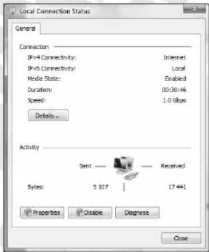
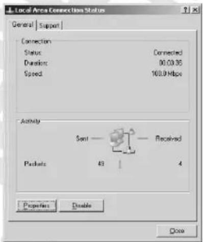
- Click View status for appropriate connection.
-
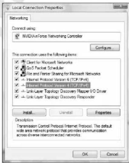
On General tab, Click the Properties button.
-
On General tab, select Internet Protocol Version 4 (TCP/IPv4) and click Properties.

Network and Internet
View network status and fusion
Set up file sharing

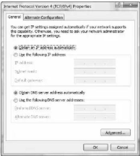
- On General tab, select Obtain an IP address automatically and Obtain DNS server address automatically.
- Click OK to save settings and close Internet Protocol Version 4 (TCP/IPv4) Properties window.
Windows 2000/XP
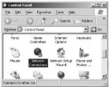
- Click Start → Settings → Control Panel. Double-click the Network Connections icon (2000/XP Classic view) or click Network and Internet Connections icon and then Network Connections icon (XP Default view).
- Double-click the Local Area Connection icon.
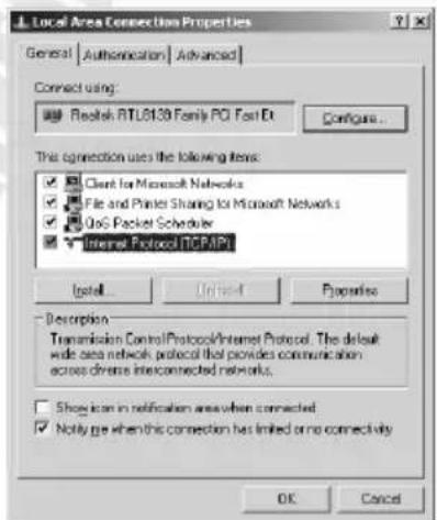
- On General tab, Click the Properties button.
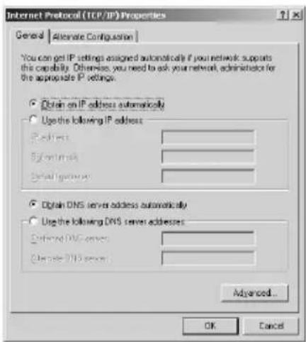
- On General tab, select Internet Protocol (TCP/IP) and click Properties.
- On General tab, select Obtain an IP address automatically and DNS server address automatically.
- Click OK to save settings and close Internet Protocol (TCP/IP) Properties window.
Windows 95/98/Me
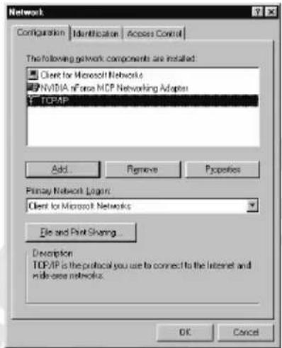
- Click Start → Settings → Control Panel. Double-click the Network icon.
- On Configuration tab, select TCP/IP for appropriate network adapter and click Properties.
- On IP Address tab, select Obtain an IP address automatically.
- On DNS Configuration tab, select Disable DNS
- Click OK to save settings and close TCP/IP Properties window.
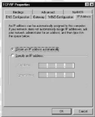
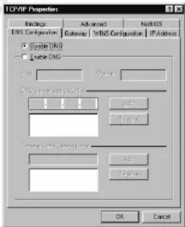
To make sure that network adapter properly obtained an IP address from router's DHCP server, click Start > Run and type cmd (Win 2000/XP) or command (Win 95/98/ME). In command line type ipconfig /all and check that value of the IP Address is 192.168.1.x
Configure router via web browser
Cerberus ADSL2+ Wi-Fi router can be configured via web browser, which is usually integrated with operating system. Router offers clear and simple interface.
Login
- Launch the Web browser
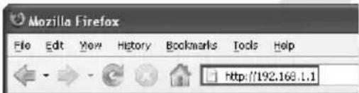
- In address bar enter the default IP address: http://192.168.1.1
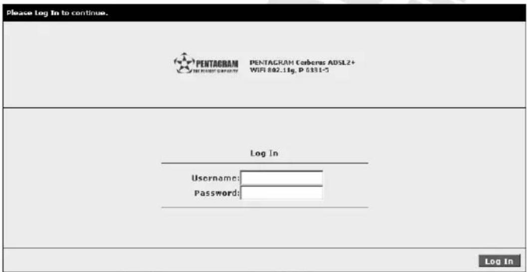
- Enter username and password – default admin / admin
Navigation
Buttons
- Apply – Click to implement the configuration changes. Clicking Apply will not implement the changes when the router is restarted.
- Cancel – Click to revert to the last saved configuration.
Commands
- Save Settings – Click to permanently apply configuration changes.
- Restart Access Point – Restarts the wireless connection
- Restart Router – Restarts the router.
Tabs
The web interface includes the following tabs:
- Setup
- Basic
- Advanced
- Wireless
- Security
- Status
- Help
Glossary:
- Multiplexing - Two conventions identify what protocols a virtual circuit (VC) is carrying. Be sure to use the multiplexing method your ISP requires:
VC-Based Multiplexing – In VC-based multiplexing, by prior mutual agreement, each protocol is assigned to a specific virtual circuit. For example, VC1 carries IP, etc. VC-based multiplexing may be dominant in environments where dynamic creation of large numbers of ATM VCs is fast and economical.
LLC-Based Multiplexing – In LLC-based multiplexing, one VC carries multiple protocols with protocol-identifying information contained in each packet header. While this method requires extra bandwidth and processing overhead, this method may be advantageous if it is not practical to have a separate VC for each carried protocol; for example, if charging heavily depends on the number of simultaneous VCs.
- VPI and VCI - Be sure to use the Virtual Path Identifier (VPI) and Virtual Channel Identifier (VCI) numbers assigned to you. The valid range for the VPI is 0 to 255. The valid range for the VCI is 32 to 65535. 0 to 31 is reserved for local management of ATM traffic.
- PPPoA – Point-to-Point Protocol over ATM Adaptation Layer 5 (AAL5) (PPPoA) provides access control and billing functionality in a manner similar to dial-up services using PPP. The router encapsulates the PPP session based on RFC1483 and sends it through ATM PVC to the ISP's DSLAM.
- PPPoE – Point-to-Point Protocol over Ethernet provides access control and billing functionality in a manner similar to dial-up services using PPP. The router bridges a PPP session over Ethernet (PPP over Ethernet, RFC 2516) from your computer to an ATM Permanent Virtual Circuit (PVC) that connects to the ADSL Access Concentrator, where the PPP session terminates. Single PVC can support any number of PPP sessions from your LAN.
Setup Tab
This tab allows you to complete the initial device configuration. It is strongly recommended to use Setup to configure your settings.
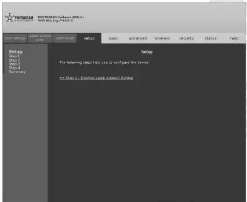
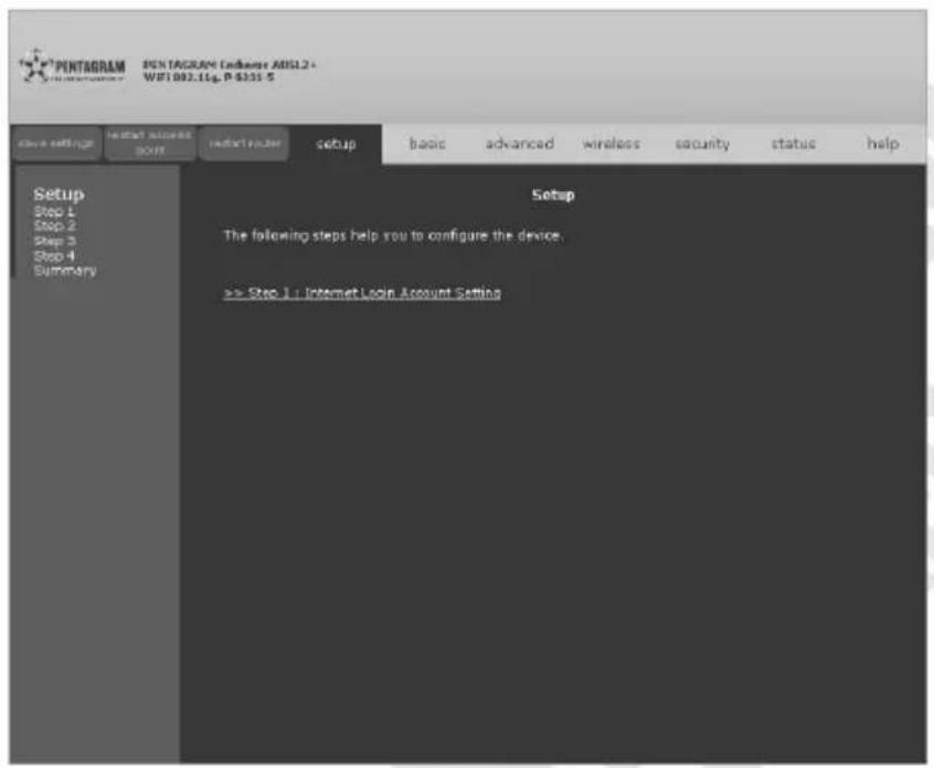
Click Step 1: Internet Login Account Setting to continue.
Internet Login Account Setting
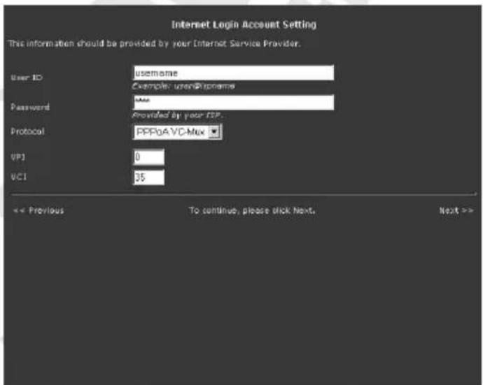
Enter User ID, Password, VPI (Virtual Path Identifier), VCI (Virtual Channel Identifier) and select your Protocol (Encapsulation) from the dropdown list. Note that you must enter the user name exactly as your ISP assigned it. If the assigned name is in the form of user@domain where domain identifies a service name, enter it exactly as given.
Click Previous to return to the previous screen or Next to continue.
Wireless LAN Configuration
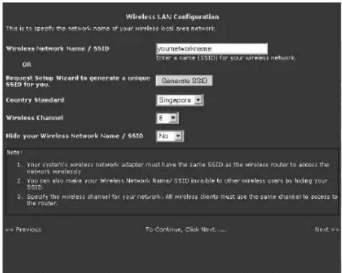
Enter Wireless Network Name / SSID or click Generate SSID to automatically generate unique SSID for your WLAN. Also from the dropdown lists select your Country Standard, Wireless Channel and choose from Hide your Wireless Network Name / SSID whether your network SSID will be hidden.
Click Previous to return to the previous screen or Next to continue.
Wireless LAN Security
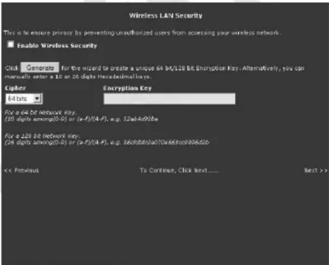
Select Enable Wireless Security checkbox (strongly recommended), from Cipher dropdown list choose key length (64 bits or 128 bits) and either Generate or enter your own Encryption Key. This will enable WEP authentication, you can change WEP Key or select different authentication type at any time in Security menu of Wireless Tab.
Click Previous to return to the previous screen or Next to continue.
System Password
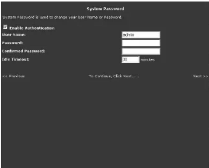
Select Enable Authentication checkbox (strongly recommended), enter User Name and password in Password and Confirmed Password fields and enter Idle Timeout. Use entered User Name and Password when accessing router's Web Interface.
Click Previous to return to the previous screen or Next to continue.
Summary
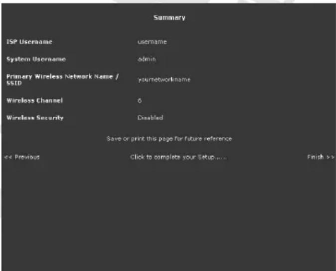
If information on this page is correct you can save or print this page.
Click Previous to return to the previous screen or Finish to save settings and restart router.
Basic Tab
This tab provides most basic information and configuration you need to configure router.
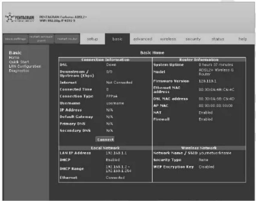
Home
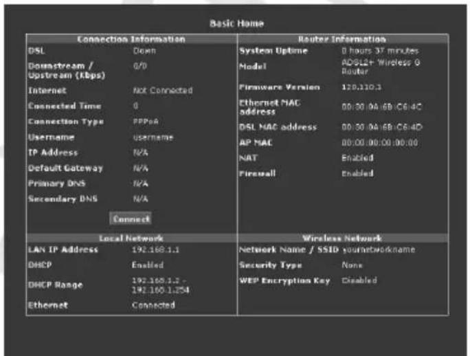
On this page you will find all information regarding connection, router and local/wireless network. If Internet connection is Down click Connect and router will try to establish connection.
Quick Start
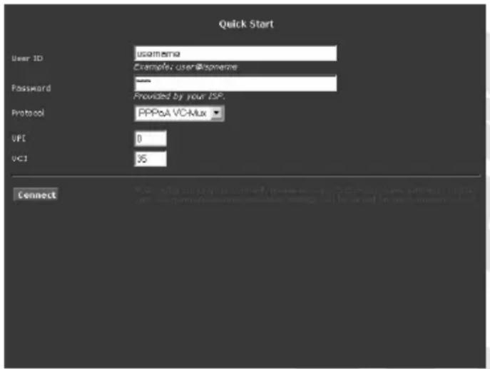
User ID – Enter your username for your PPPoE/PPPoA connection.
Password – Enter your password for your PPPoE/PPPoA connection.
Protocol – Select your encapsulation and multiplexing type from the dropdown list.
VPI – Virtual Path Identifier. The valid range for the VPI is 0 to 255.
VCI – Virtual Channel Identifier. The valid range for the VCI is 1 to 65635 (0 to 31 is reserved for local management of ATM traffic).
Connect – Establish connection using above parameters.
LAN configuration
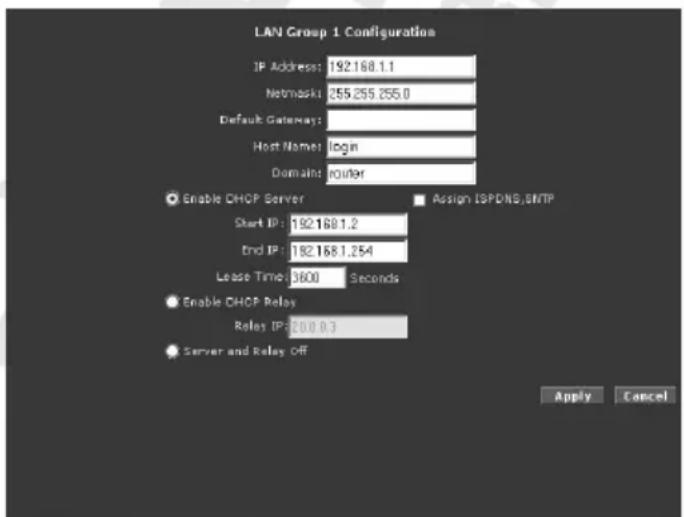
IP Address – The default IP address of the router (as shown) is 192.168.1.1.
Netmask – The default subnet mask of your router is 255.255.255.0. This subnet allows the router to support 254 users. If you want to support a larger number of users you can change the subnet mask.
Default Gateway – The default gateway is the routing device used to forward all traffic that is not addressed to a station within the local subnet. Your ISP provides you with the IP address of the default gateway.
Host Name – The host name is used in conjunction with the domain name to uniquely identify the router. It can be any alphanumeric word that does not contain spaces.
Domain – The domain name is used in conjunction with the host name to uniquely identify the router. To access the web pages of the router you can type 192.168.1.1 (the IP address) or mygateway1.ar7 (Host Name.Domain).
Enable DHCP Server – Enables/disables DHCP. By default, your router has the DHCP server (LAN side) enabled. If you already have a DHCP server running on your network, you must disable one of the two DHCP servers.
Assign ISPDNS, SNTP – If enabled the router will advertise its own IP address as the DNS server, when disabled the router will provide the DNS that was received from the WAN.
Start IP / End IP – Enter the starting/ending IP address which will be assigned to devices using DHCP
Lease Time – The Lease Time is the amount of time that a network user is allowed to maintain a network connection to the router using the current dynamic IP address. At the end of the Lease Time, the lease is either renewed or the DHCP server issues a new IP. The amount of time is in units of seconds. The default value is 3600 seconds (1 hour). The maximum value is 999999 seconds (About 278 hours).
Enable DHCP Relay – In addition to the DHCP server feature, the router supports the DHCP relay function. When the router is configured as DHCP server, it assigns the IP addresses to the LAN clients. When the gateway is configured as DHCP relay, it is responsible for forwarding the requests and responses negotiated between the DHCP clients and the server.
Relay IP – The IP address of the DHCP relay server.
Server and Relay Off – When the DHCP server and relay functions are turned off, the network administrator must carefully configure the IP address, Subnet Mask, and DNS settings of every host on your network. Do not assign the same IP address to more than one host. Also, your router must reside on the same subnet as all the other hosts.
Diagnostics
Diagnostic Test is used for investigating whether the router is properly connected to the WAN Network. This test may take a few seconds to complete. Before running this test, make sure you have a valid DSL link.
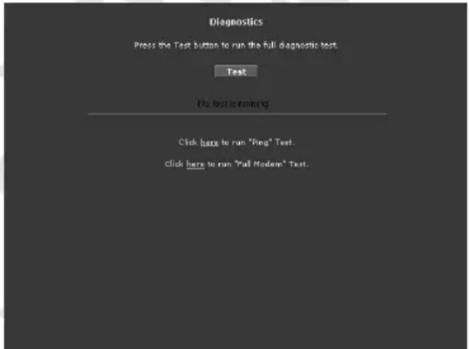
To perform the test, select your connection from the list and press the Test button. You can also perform "Ping" Test or "Full Modem" Test:
- Ping Test
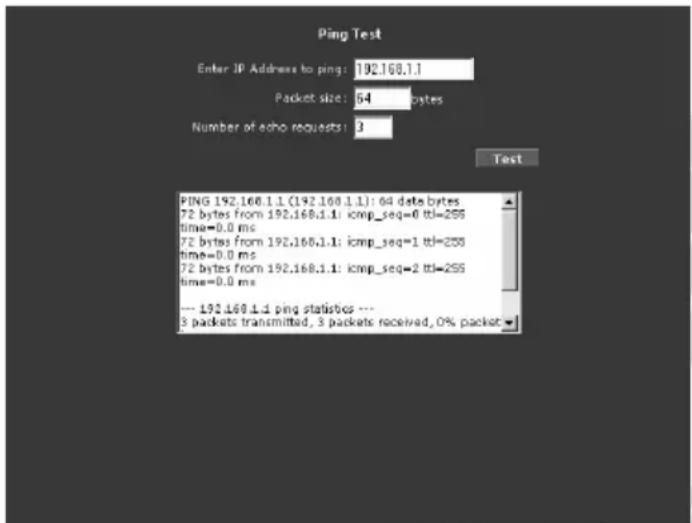
Change or leave the default settings of the following fields: Enter the IP address to ping, Packet size and Number of echo request and click Test. The ping results are displayed in the page. If the ping test was successful, it means that the TCP/IP protocol is up and running. If the Ping test failed, you should restart the router.
• Full Modem Test
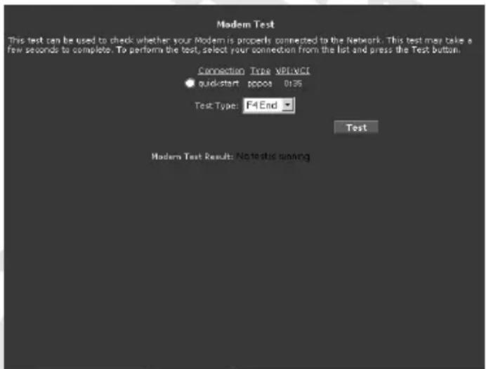
Select your Connection and Test Type to perform, then click Test.
Advanced Tab
The Advanced tab provides advanced configuration settings for existing connections. At least one WAN connection must be configured before implementing advanced WAN configuration features. At least one LAN group must be defined before implementing advanced LAN configuration features.
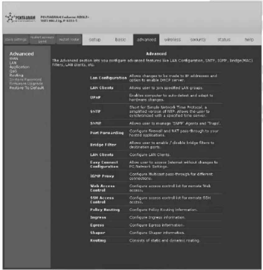
WAN / New Connection
This page appearance is dependent on selected Type of connection. Saved connections will be available from the bottom of WAN menu.
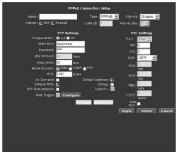
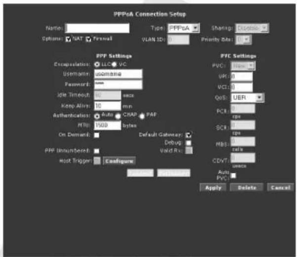
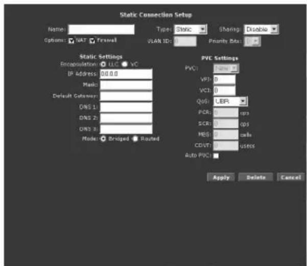
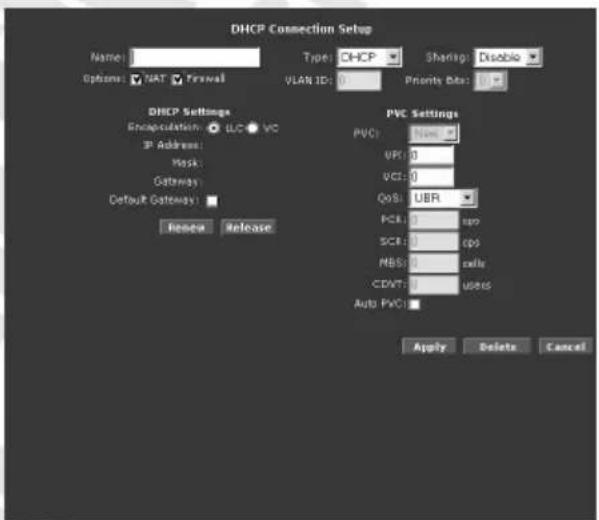
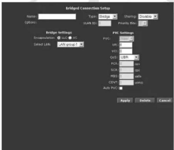
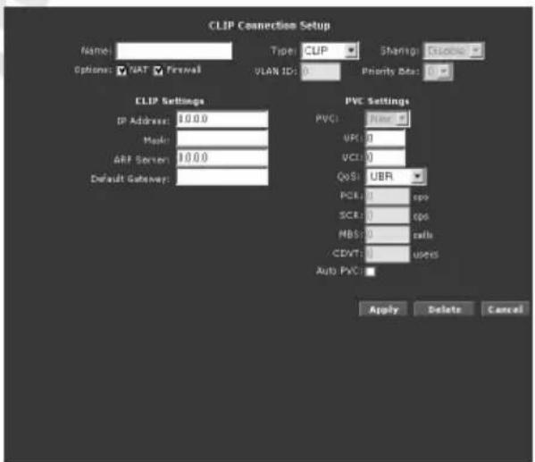
Name – Name for this connection.
Type – Protocol used to establish this connection.
Sharing – Select type of sharing for this connection: Disabled, Enabled or VLAN.
Options – Enable or disable NAT/Firewall services for this connection.
VLAN ID – Enter VLAN identifier.
Priority Bits – Define User Priority for VLAN.
PVC Settings
PVC – Select predefined Virtual Circuit you want to use (only when Enabled or VLAN is selected from Sharing list).
VPI – Virtual Path Identifier. The valid range for the VPI is 0 to 255.
VCI – Virtual Channel Identifier. The valid range for the VCI is 1 to 65635 (0 to 31 is reserved for local management of ATM traffic).
QoS – Select the Quality of Service types for this Virtual Circuit. The ATM QoS types include
CBR (Constant Bit Rate), VBR (Variable Bit Rate) and UBR (Unspecified Bit Rate). These QoS types are all controlled by the parameters specified below, including PCR, SCR, and MBS.
CBR (Constant Bit Rate) – is for connections that support constant rates of data transfer. The only parameter you need to worry about in CBR is PCR.
UBR (Unspecified Data Rate) – is for connections that have variable traffic. The only parameter you need to worry about in UBR is PCR.
rtVBR (real time Variable Bit Rate) – is for connections that, while having variable traffic, require precise timing between traffic source and destination. PCR, SCR and MBS must all be set for rtVBR.
nrtVBR (non real time Variable Bit Rate) – is for connections that have variable traffic, do not require precise timing, but still require a set bandwidth availability. PCR, SCR and MBS must all be set for nrtVBR.
PCR (Peak Cell Rate) – Peak Cell Rate (PCR) is the maximum rate at which the sender can send cells. This parameter may be lower (but not higher) than the maximum line speed. 1 ATM cell is 53 bytes (424 bits), so a maximum speed of 832 Kbps gives a maximum PCR of 1962 cells/sec. This rate is not guaranteed because it is dependent on the line speed.
SCR (Sustained Cell Rate) – Sustained Cell Rate (SCR) is the mean cell rate of a burst, on-off traffic source that can be sent at the peak rate, and a parameter for burst-type traffic. SCR may not be greater than the PCR; the system default is 0 cells/sec.
MBS (Maximum Burst Size) – Maximum Burst Size (MBS) is the maximum number of cells that can be sent at the PCR. After MBS is reached, cell rates fall below SCR until cell rate averages to the SCR again. At this time, more cells (up to the MBS) can be sent at the PCR again.
CDVT (Cell Delay Variation Tolerance) – ATM network tolerance to cells spacing.
Auto PVC – Router will try to automatically configure PVC parameters.
Selected Type dependent settings
- PPP Settings (PPPoA/PPPoE)
Encapsulation – Select your encapsulation type.
Username – Enter your username for your PPPoE/PPPoA connection.
Password – Enter your password for your PPPoE/PPPoA connection.
Idle Timeout – When On Demand function is selected, specify how many minutes the connection may be idle before it disconnects.
Keep Alive – Enter time between sending Keep Alive packets.
Authentication – Select authentication method for connection: Auto (recommended), CHAP (Challenge Handshake Authentication Protocol) or PAP (Password Authentication Protocol).
MTU – Enter TCP MTU (Maximum Transmission Unit) value here.
On Demand – Recommended for connections charged on time used.
Default Gateway – Select whether default gateway will be used or not.
Enforce MTU (PPPoE only) – Check this option to enforce MTU value.
PPP Unnumbered – IP address is not assigned to PPP connection (not recommended).
Host Trigger – When On Demand is enabled, select this checkbox and click Configure to set triggers which will enable connection.
- Static Settings
Encapsulation – Select your encapsulation type.
IP Address – Enter the static IP address here.
Mask – Enter the IP subnet mask here.
Default Gateway – Enter the gateway here.
DNS 1-3 – Enter IP address of primary, secondary and tertiary DNS Server.
Mode – Select if this connection will be Bridged or Routed.
- DHCP Settings
Encapsulation, IP Address, Mask, Gateway – Parameters obtained from DHCP Server.
Default Gateway – Select this option if you want to use default gateway for this connection.
Use buttons to Renew or Release parameters obtained from DHCP Server.
- Bridge Settings
Encapsulation – Select your encapsulation type.
Select LAN – Select LAN Group from which packets will be bridged to WAN port.
- CLIP
IP Address – Enter IP Address.
Mask – Enter the IP subnet mask here.
ARP Server – Enter IP Address of ARP Server.
Default Gateway – Enter the gateway here.
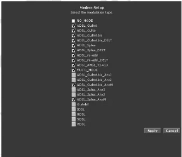
WAN / ADSL Modulation
ADSL Modulation allows you to select any combination of DSL training modes. Leave the default value if you are unsure or the service provider did not provide this information. In most cases, this screen should not be modified.
WAN / Connection Scan
This feature helps users to detect the PVC settings provided by the service provider. Before the router can begin scanning the connection, the telephone line has to be plugged into the router.
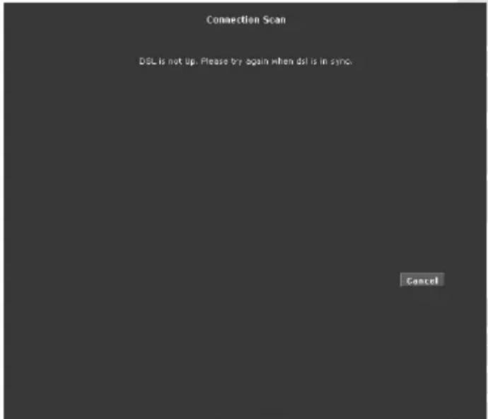
Click Scan to perform connection scan.
LAN / LAN Configuration
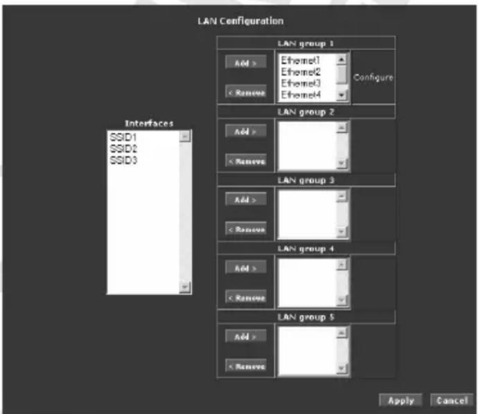
Interfaces – List of available unassigned interfaces.
LAN Group 1-5 – Each LAN Group can be configured as entire different subnet and you can freely assign routers network interfaces to any group. To add interface to LAN group select this interface and click Add for desired group. If you wish to remove interface from group, select it and click Remove. If group contains at least one interface, you can click Configure to open LAN Group x Configuration.
• LAN Group x configuration
LAN Group Configuration allows you to configure settings for each LAN group. Notice that you can also view the status of advanced services that can be applied to a LAN group. Green indicates that the service is enabled, while red indicates that the service is disabled.
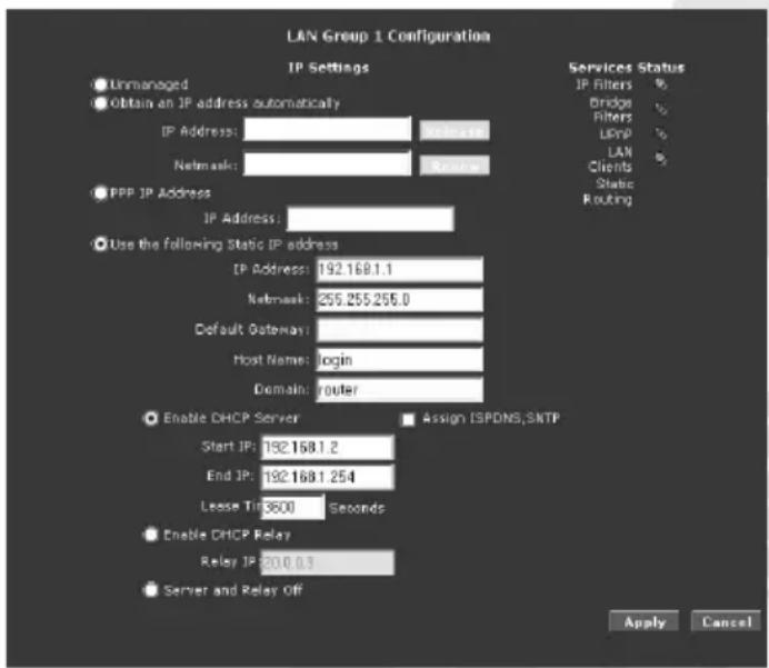
Unmanaged
Unmanaged is a state when the LAN group is not configured and no IP address has been assigned to the bridge.
Obtain IP address automatically
When this function is enabled, your router acts like a client and requests an IP address from the DHCP server on the LAN side. You can release/renew an IP address from the DHCP server using the Release and Renew buttons. Assigned IP Address and Netmask will be displayed fields.
PPP IP Address
Enables/disables PPP unnumbered feature. Entered IP Address should be different but within the same subnet as the WAN-side IP address.
Use the following Static IP address
This field enables you to change the IP address of the router.
IP Address – The default IP address of the router (as shown) is 192.168.1.1.
Netmask – The default subnet mask of your router is 255.255.255.0. This subnet allows the router to support 254 users. If you want to support a larger number of users you can change the subnet mask.
Default Gateway – The default gateway is the routing device used to forward all traffic that is not addressed to a station within the local subnet. Your ISP provides you with the IP address of the default gateway.
Host Name – The host name is used in conjunction with the domain name to uniquely identify the router. It can be any alphanumeric word that does not contain spaces.
Domain – The domain name is used in conjunction with the host name to uniquely identify the router. To access the web pages of the router you can type 192.168.1.1 (the IP address) or mygateway1.ar7 (Host Name.Domain).
Enable DHCP Server – Enables/disables DHCP. By default, your router has the DHCP server (LAN side) enabled. If you already have a DHCP server running on your network, you must disable one of the two DHCP servers.
Assign ISPDNS, SNTP – If enabled the router will advertise its own IP address as the DNS server, when disabled the router will provide the DNS that was received from the WAN.
Start IP / End IP – Enter the starting/ending IP address which will be assigned to devices using DHCP
Lease Time – The Lease Time is the amount of time that a network user is allowed to maintain a network connection to the router using the current dynamic IP address. At the end of the Lease Time, the lease is either renewed or the DHCP server issues a new IP. The amount of time is in units of seconds. The default value is 3600 seconds (1 hour). The maximum value is 999999 seconds (About 278 hours).
Enable DHCP Relay – In addition to the DHCP server feature, the router supports the DHCP relay function. When the router is configured as DHCP server, it assigns the IP addresses to the LAN clients. When the gateway is configured as DHCP relay, it is responsible for forwarding the requests and responses negotiated between the DHCP clients and the server.
Relay IP – The IP address of the DHCP relay server.
Server and Relay Off – When the DHCP server and relay functions are turned off, the network administrator must carefully configure the IP address, Subnet Mask, and DNS settings of every host on your network. Do not assign the same IP address to more than one host. Also, your router must reside on the same subnet as all the other hosts.
LAN / LAN Clients
LAN Clients allows you to view and add computers in a LAN group. Each computer either has a dynamic or static (manually-configured) IP address. You can add a static IP address (belonging to the router's LAN subnet) using the LAN Clients page. Any existing static entry falling within the DHCP server's range can be deleted.
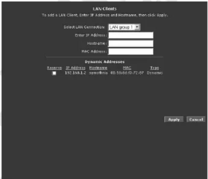
Select LAN Connection – Select LAN Group you want to edit.
Enter IP Address / Hostname / MAC Address – Fill out this fields and click Apply to add specific host to Static Addresses list.
Static Addresses – List of all hosts which will obtain always the same IP address from DHCP server – this addresses won't be assigned to other hosts. Select Delete checkbox and click Apply to delete selected host from Static Addresses list. During next connection this host will obtain new dynamic IP Address.
Dynamic Addresses – List of all host which obtained IP address from router's DHCP server.
Select Reserve checkbox and click Apply to move selected host to Static Addresses list.
Application / UPnP
Universal plug and play (UPnP), NAT, and firewall traversal allow traffic to pass through the router for applications using the UPnP protocol. This feature requires one active WAN connection. In addition, the computer should support this feature. In the presence of multiple WAN connections, select a connection on which the incoming traffic is present, for example, the default WAN connection.
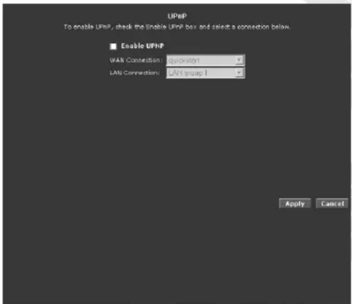
Enable UPnP – Select to enable UPnP.
WAN Connection – Select WAN connection that will use UPnP.
LAN Connection – Select LAN connection that will use UPnP.
Application / SNTP
Simple network timing protocol (SNTP) is a protocol used to synchronize the system time to the public SNTP servers. It uses the UDP protocol on port 123 to communicate between clients and servers.
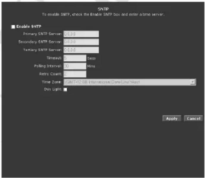
Enable SNTP – Select to enable SNTP.
Primary SNTP Server – The IP address or the host name of the primary SNTP server. This can be provided by ISP or defined by user.
Secondary SNTP Server – The IP address or the host name of the secondary SNTP server. This can be provided by ISP or defined by user.
Tertiary SNTP Server – The IP address or the host name of the tertiary SNTP server. This can be provided by ISP or defined by user.
Timeout – If the router failed to connect to an SNTP server within the Timeout period, it retries the connection.
Polling Interval – The amount of time between a successful connection with a SNTP server and a new attempt to connect to an SNTP server.
Retry Count – The number of times the router tries to connect to an SNTP server before it tries to connect to the next server in line.
Time Zone – The time zone in which the router resides.
Day Light – Select this option to enable/disable daylight saving time (DST). DST is not automatically enabled or disabled. You need to manually enable and disable it.
Application / SNMP
SNMP (Simple Network Management Protocol) is a troubleshooting and management protocol, which uses the UDP protocol on port 161 to communicate between clients and servers. SNMP uses a manager MIB (management information base) agent solution to fulfill the network management needs. The agent is a separate station that can request data from an SNMP agent in each of the different system in the network. The agent uses MIBs as dictionaries of manageable objects. Each SNMP-managed device has at least one agent that can respond to the queries from the NMS (Network Management Station). The SNMP agent supports GETS, SETS, and TRAPS for 4 groups with MIB-II: System, Interface, IP, and ICMP. The SNMP agent supports three-community names authentication.
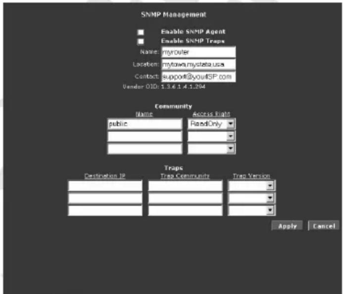
Enable SNMP Agent – Select to enable SNMP Agent on router.
Enable SNMP Traps – Select to enable SNMP Traps on router.
Name / Location / Contact – Information about device used for identification and contact.
Vendor OID – Object ID – unique identifier for this device.
Community – Enter Community Name and select Access Right for this Community.
Traps – Enter Destination IP of the SNTP manager in Trap Community – Traps will be send to this manager. You also must specify Trap Version.
Application / IGMP Proxy
IP hosts use Internet Group Management Protocol (IGMP) to report their multicast group memberships to neighboring routers. Similarly, multicast routers use IGMP to discover which of their hosts belong to multicast groups. Your router supports IGMP proxy that handles IGMP messages. When enabled, your router acts as a proxy for a LAN host making requests to join and leave multicast groups, or a multicast router sending multicast packets to multicast groups on the WAN side.
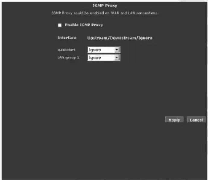
Multicasting is a form of limited broadcast. UDP is used to send datagram's to all hosts that belong to what is called a Host Group. A host group is a set of one or more hosts identified by a single IP destination address. The following statements apply to host groups:
- Anyone can join or leave a host group at will.
- There are no restrictions on a host's location.
- There are no restrictions on the number of members that may belong to a host group.
- A host may belong to multiple host groups.
- Non-group members may send UDP datagram's to the host group.
Multicasting is useful when the same data needs to be sent to more than one device. For instance, if one device is responsible for acquiring data that many other devices need, then multicasting is a natural fit. Note that using multicasting as opposed to sending the same data to individual devices uses less network bandwidth. The multicast feature also enables you to receive multicast video streams from multicast servers. The IGMP Proxy page allows you to enable multicast on available WAN and LAN connections.
You can configure the WAN or LAN interface as one of the following:
Upstream – The interface that IGMP requests from hosts are sent to the multicast router.
Downstream – The interface data from the multicast router are sent to hosts in the multicast group database.
Ignore - No IGMP request nor data multicast are forwarded.
Application / TR-068 WAN Access
The TR-068 WAN Access page enables you to give temporary permission to someone (such as technical support staff) to be able to access your router from the WAN side. From the moment the account is enabled the user is expected to log in within 20 minutes, otherwise the account expires. Once the user has logged in, if the session remains inactive for more than 20 minutes, the user will be logged out and the account expires.
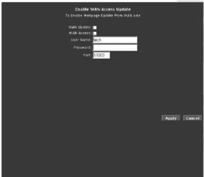
WAN Update – Permit this user to change WAN Settings.
WAN Access – Permit this user to Access WAN.
User Name / Password – Username and password needed to authenticate this connection.
Port – Port number for remote access.
To access your router remotely, enter the following URL:
http(s)://WAN IP of router:Port Number (i.e. http(s)://10.10.10.5:51003)
Application / TR-069
The TR-069 page allows you to set up connection parameters that cannot be seen by end users. TR-069 is CPE (Customer Premise Equipment) Management Protocol from WAN side, intended for communication between a CPE and Auto-Configuration Server (ACS). The CPE WAN Management Protocol defines a mechanism that encompasses secure auto-configuration of a CPE, and also incorporates other CPE management functions into a common framework.
The CPE WAN Management Protocol is intended to support a variety of functionalities to manage a collection of CPE, including the following primary capabilities:
- Auto-configuration and dynamic service provisioning
- Software/firmware image management
• Status and performance monitoring - Diagnostics
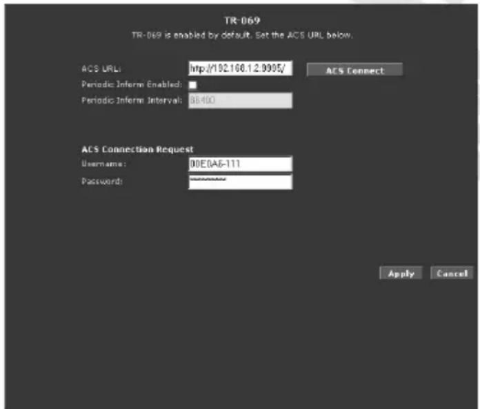
ACS URL –Address of ACS server.
Periodic Inform Enabled – Select this option if you want to enable Periodic Inform.
Periodic Inform Interval – Enter Periodic Inform Interval time.
ACS Connect – Click to connect to the ACS. When a connection is established, the ACS updates the ACS URL, Periodic Inform Enabled, and Periodic Inform Interval.
ACS Connection Request – Username and Password needed to connect to the ACS, it is best to leave this fields unchanged.
Application / NAT Services
If the user has more than one public IP address assigned by the ISP, these additional IP addresses can be used to map to servers on the LAN. One public IP address will be used to provide Internet access to the LAN computers via NAT, serving as the primary IP address of the router. The rest will be mapped to servers on the LAN.
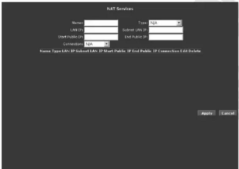
Name – Name that will be displayed in the list below.
Type – Router supports three NAT mapping types:
- One to One – One LAN IP address is mapped to one public IP address.
- Many to Many – Multiple local IP addresses are mapped to shared public IP addresses.
- Server – Specify inside servers of different services behind the NAT to be accessible to the outside world.
LAN IP – IP address of host in local network.
Subnet LAN IP – Available only for Many to Many. Specify subnet of LAN IP addresses
Start Public IP – Public IP address for One to One or Server mapping. Starting public IP address for Many to Many mapping.
End Public IP – Ending public IP address for Many to Many mapping.
Connection – WAN connection which will be used for this NAT mapping.
Application / DNS Proxy
DNS Proxy determines the primary Domain Name Server and secondary DNS to be used.
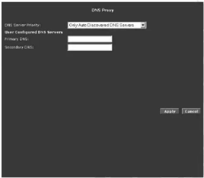
DNS Server Priority – Select which DNS Servers will be used: Auto Discovered (resolved automatic during connection) or User Configured (entered in fields below):
- Only Auto Discovered DNS Servers
- Only User Configured DNS Servers
• Auto Discovered then User Configured
- User Configured then Auto Discovered
Primary / Secondary DNS – Enter IP address of primary and secondary DNS Server.
Application / Dynamic DNS Client
Dynamic DNS allows the user to register with a Dynamic DNS Provider. The Dynamic DNS will be linked with the WAN IP of the router even after the ISP update the WAN IP to another IP address. It can be useful in web hosting and FTP services. You need to have registered a DDNS account with DDNS Provider, i.e. DynDNS (free of charge) – http://www.dyndns.org or TZO – http://www.tzo.com.
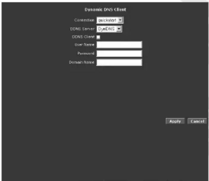
Connection – WAN connection which will use DDNS settings.
DDNS Server – DDNS service provider.
DDNS Client – Select this checkbox to enable DDNS.
User Name – Type the username assigned to you by your DDNS provider.
Password – Type the password assigned to you by your DDNS provider.
Domain Name – Type the domain name assigned to you by your DDNS provider.
Application / Easy Connect Configuration
Easy Connect feature allow user to surf web with ease without the need to changes default configuration setting, i.e. TCP/IP, Proxy, DNS of user's computer.
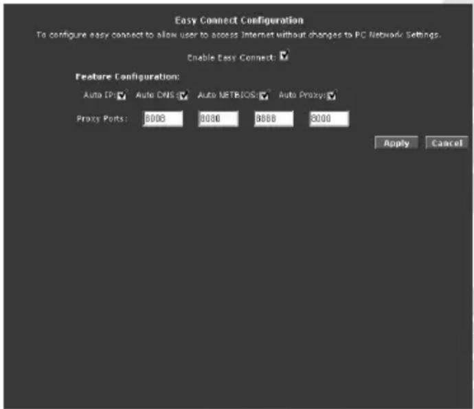
Enable Easy Connect – Select checkbox to Enable this function.
Auto IP – All valid TCP/IP setting on user's computer can surf web via the router without the need to change the IP address
Auto DNS – Any DNS IP address set at user's computer irregardless whether the address is valid or invalid DNS, Auto DNS still allow user's computer to surf the web.
Auto NetBIOS – It allows proxy server to use any NetBIOS name which the Auto NetBIOS still allow computer to surf the web with a condition that the router gateway MUST be in Private IP Ranges.
Private IP Ranges:
Class A: 10.0.0.0 \~ 10.255.255.255
Class B: 172.16.0.0 \~ 172.31.255.255
Class C: 192.168.0.0 \~ 192.168.255.255
Auto Proxy – Refers to any valid Private IP proxy setting with any port number. For example, when you enter 1234 on the browser, Auto Proxy will still allow the computer to surf the web.
Any Public IP proxy setting will assume the proxy is valid and hence Auto Proxy function will not take place. Note: The port number to be used must be specified in both the browser and the Auto Proxy Ports.
Application / Port Triggering
Port triggering is a specialized form of port forwarding which enables computers behind NAT to be accessed. It triggers open an incoming port when a client on the LAN makes an outgoing connection to a predetermined port on a server.
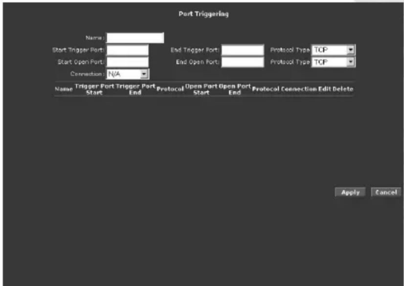
Name – Enter rule name.
Start / End Trigger Port – Enter range of ports on server that must be accessed from LAN computer to open incoming port(s).
Start / End Open Port – Enter port that will be opened when trigger port is accessed.
Protocol Type – Select protocol that will be used to trigger port or will be allowed to access open port.
Connection – WAN connection which will use Port Triggering settings.
Application / Port Forwarding
Port forwarding (or virtual server) allows you to direct incoming traffic to specific LAN hosts based on a protocol port number and protocol. Using the Port Forwarding page, you can provide local services (for example, web hosting) for people on the Internet or play Internet games. Port forwarding is configurable per LAN group.
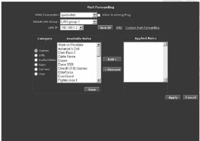
WAN Connection – Select WAN connection used for Port Forwarding.
Allow Incoming Ping – Select to allow incoming Ping packets to reach your LAN.
Select LAN Group / LAN IP – Select Group and then enter LAN IP address of host which rules you want to configure.
New IP – Opens LAN Clients page where you can add new static IP address (refer to LAN / LAN Clients section for more details).
DMZ – Opens DMZ Settings page where you can enable and configure DMZ settings.
Custom Port Forwarding – Opens Custom Port Forwarding page where you can create more advanced rules.
Category – Rules are grouped based on their purpose. You can create your own rules in User Category.
Available Rules – List of all available rules in selected category. Select rule and click Add to add this rule to Applied Rules list.
Applied Rules – List of all active rules for selected host. Select rule and click Remove to remove this rule from Applied Rules list.
New – Active only under User category. Opens Rule Management page.
View – Opens Rule Management page with details of selected rule.
Delete – Active only under User category. Use this button to delete selected rule.
You can open below pages from Port Forwarding page:
• Rule Management (New Rule)
The Rule Management page allows you to create new rules. To create new rule enter Rule Name, Protocol, Port Start, Port End, and Port Map, and then click Apply. Created rules can be also used to set IP Filters (Security Tab).
• DMZ
Setting a host on your local network as demilitarized zone (DMZ) forwards any network traffic that is not redirected to another host via the port forwarding feature to the IP address of the host. This opens the access to the DMZ host from the Internet. This
function is disabled by default. By enabling DMZ, you add an extra layer of security protection for hosts behind the firewall.
To enable DMZ select Enable DMZ checkbox, then select DMZ host parameters from Select your WAN Connection, Select LAN Group, and Select LAN IP Address lists and click Apply.
- Custom Port Forwarding
The Custom Port Forwarding page allows you to create up to 15 custom port forwarding entries to support specific services or applications, such as concurrent NAT/NAPT operation.
Application / Bridge Filters
The Bridge Filters allows you to enable, add, edit, or delete the filter rules. When bridge filtering is enabled, each frame is examined against every defined filter rule in sequence. When a match is found, the appropriate filtering action (allow or deny) is performed. Up to 20 filter rules are supported with bridge filtering.
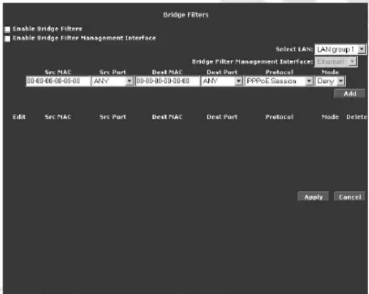
Enable Bridge Filters – Select to enable Bridge Filters function.
Enable Bridge Filters Management interface – Select to enable specified in Bridge Filters Management interface list interface for Bridge Filters Management.
Select LAN – Select LAN Group which rules you want to configure.
To add a rule, enter the Src MAC (source MAC address), Dest MAC (destination MAC address), and choose from lists Src Port (source port), Dest Port (destination port), Protocol and desired filtering Mode, then click Add. You can also edit a rule that you created using the Edit checkbox. You can delete using Delete.
Application / Web Access Control
The Web Access Control page allows you to access the router via the web from a remote location like your home or office.
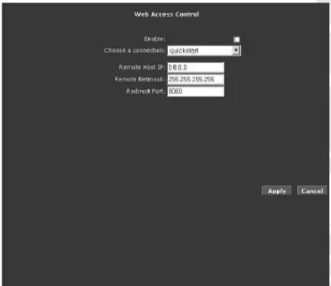
Enable – Select to enable access to router from WAN.
Choose a connection – Select WAN connection used for WAN Access.
Remote Host IP – IP address of host which will be allowed to access router from WAN.
Remote Netmask – Changing Netmask will allow more than one IP address to access router from WAN.
Redirect Port – Port needed to access router from WAN.
Application / SSH Access Control
SSH Access control allows you to access the router remotely via SSH from the WAN side.
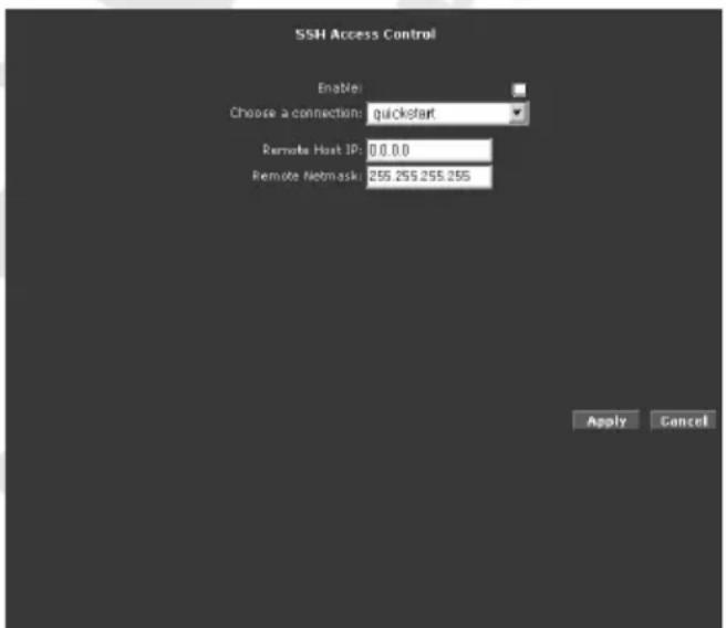
Enable – Select to enable SSH access to router from WAN.
Choose a connection – Select WAN connection used for SSH Access.
Remote Host IP – IP address of host which will be allowed to access router from WAN.
Remote Netmask – Changing Netmask will allow more than one IP address to access router from WAN.
QoS
Quality of service allows network administrators to configure the routers to meet the real time requirements for voice and video.
Different networks use different QoS markings like:
- ToS network: ToS bits in the IP header
• VLAN network: priority bits in the VLAN header
• DSCP network: uses only 5 bits of the CoS - WLAN: WLAN QoS header.
The QoS framework is supported on all the above domains. How do you make them talk to each other? How can you make sure the priority from one network is carried over to another network? Class of service (CoS) is introduced as the common language for the QoS mappings. When QoS is enabled, the router has full control over packets from the time they enter the router till they leave the router. This is how it works: The domain mapping (ToS bits, priority bits, etc.) of a packet needs to be translated to CoS when the packet enter the router, and vice versa, the CoS of a packet needs to be translated back to the domain mapping when the packet leaves the router.
There are 6 types of CoS (in descending priority):
- CoS1 has absolute priority and is used for expedited forwarding (EF) traffic. This is always serviced till completion.
- CoS2-CoS5 are used for assured forwarding (AF) classes. They are serviced in a strict round robin manner using the following priority scheme:
$$ \mathrm{CoS2} > \mathrm{CoS3} > \mathrm{CoS4} > \mathrm{CoS5} $$
- CoS6 is for best effort (BE) traffic. This is only serviced when there is no other class of service. If QoS is not enabled on your router, all traffic will be treated as best effort.
There are some additional terms you should get familiarize with:
- Ingress: Packets arriving into the router from a WAN/LAN interface.
- Egress: Packets sent from the router to a WAN/LAN interface.
- Trusted mode: Honors the domain mapping (ToS byte, WME, VLAN user priority).
- Untrusted mode: Does not honor domain mapping. This is the default QoS setting.
-
Traffic Conditioning Agreement (TCA): The TCA needs to be defined for each interface:
-
Ingress mappings (Domain =>CoS)
- Egress Mappings (CoS => Domain)
- Untrusted mode (default)
- Shaper
QoS / Egress
For packets going out of the router, the markings (CoS) need to be translated to the mappings understood by the network domains. The reverse CoS and domain mapping is configured using the Egress.
There are three Egress modes:
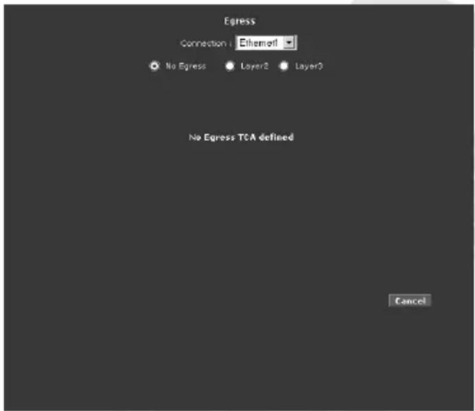
- No Egress Mode
The default Egress page setting for all interfaces is No Egress. In this mode, the domain mappings of the packets are untouched.
- Layer 2
The Egress Layer 2 page allows you to map the CoS of an outgoing packet to user priority bits, which is honored by the VLAN network. Again, this feature is only configurable on the WAN interfaces as VLAN is only supported on the WAN side in the current release.
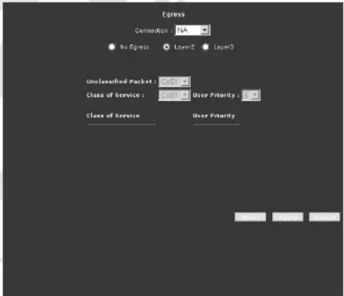
Interface – Select the WAN interface to configure the QoS for outgoing packets; LAN interface cannot be selected as VLAN is currently supported on the WAN side only.
Unclassified Packet – Some locally generated packets might not have been classified and thus do not have a CoS value, such as PPP control packet and ARP packet. You can define the CoS for all unclassified outgoing packets on layer 2 using this field, which will then pick up the user priority bits based on the mapping rules you create. The selections are (in the order of descending priority): CoS1, CoS2, CoS3, CoS4, CoS5, and CoS6. The default value is CoS1 (recommended).
Class of Service – The selections are (in the order of descending priority): CoS1, CoS2, CoS3, CoS4, CoS5, and CoS6.
User Priority – The selections are 0, 1, 2, 3, 4, 5, 6, 7.
- Layer 3
Egress Layer 3 enables you to map CoS to ToS so that the priority marking of outgoing packets can be carried over to the IP network.
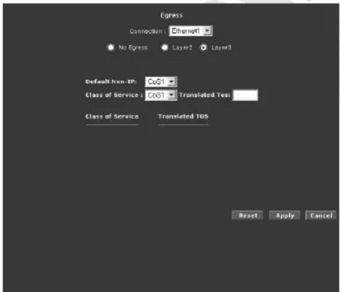
Interface – Select the interface to configure the QoS for outgoing packets.
Default Non-IP – Locally generated packets (such as ARP packets) do not have a CoS marking. You can define the CoS for all unclassified outgoing packets on layer 3 using this field. The selections are in the order of descending priority): CoS1, CoS2, CoS3, CoS4, CoS5, and CoS6. The default value is CoS1 (recommended).
Class of Service – The selections are (in the order of descending priority): CoS1, CoS2, CoS3, CoS4, CoS5, and CoS6.
Translated TOS – The Type of Service field takes values from 1 to 255.
QoS / Ingress
Ingress enables you to configure QoS for packets as soon as they come into the router. The domain mappings are converted to CoS (the common language) so that the priority marking is carried over.
There are four Ingress modes:
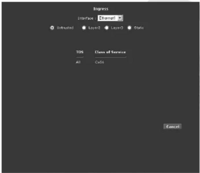
- Untrusted Mode
Untrusted is the default Ingress page setting for all interfaces. In this mode, no domain mapping is honored in the router. All packets are treated as CoS6 (best effort).
- Layer 2
Layer 2 allows you to map an incoming packet with VLAN priority to CoS. This feature is only configurable on the WAN interfaces as VLAN is only supported on the WAN side in the current software release.
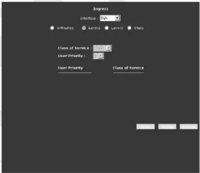
Interface – Select the WAN interface here to configure the CoS for incoming traffic. Only WAN interface can be selected as VLAN is currently supported only on the WAN side.
Class of Service – The selections are (in the order of descending priority): CoS1, CoS2, CoS3, CoS4, CoS5, and CoS6.
User Priority – The selections are 0, 1, 2, 3, 4, 5, 6, 7.
Notes:
- Any priority bits that have not been mapped to a CoS default to CoS6, the lowest priority.
- Any WAN interface that is not configured has the default Untrusted mode.
- Layer 3
The Layer 3 page allows you to map ToS bits of incoming packets from the IP network to CoS for each WAN/LAN interface.
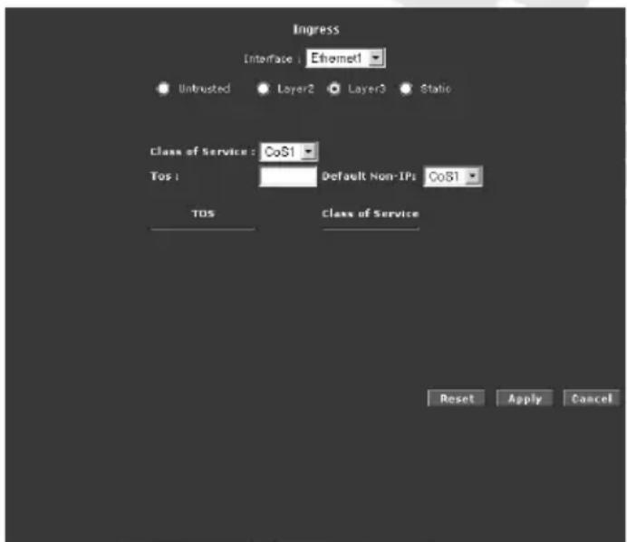
Interface – For both WAN and LAN interfaces, you can configure QoS for layer 3 (IP) data traffic.
Class of Service – This CoS field allows you to map incoming layer 3 WAN/LAN packets to one of the following CoS (in the order of descending priority): CoS1, CoS2, CoS3, CoS4, CoS5, and CoS6.
ToS – The Type of Service field takes values from 0 to 255.
Default Non-IP – A static CoS can be assigned to all layer 3 incoming packets (per interface) that do not have an IP header, such as PPP control packets and ARP packets. The default is CoS1 (recommended).
Notes:
- Any priority bits that have not been mapped to a CoS default to CoS6, the lowest priority.
- Any WAN interface that is not configured has the default Untrusted mode.
- Static
The Ingress - Static page enables you to configure a static CoS for all packets received on a WAN or LAN interface.
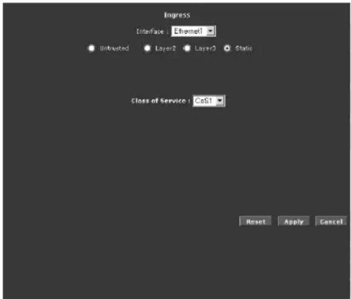
Interface – Select the interface here to configure the CoS for incoming traffic.
Class of Service – The selections are (in the order of descending priority): CoS1, CoS2, CoS3, CoS4, CoS5, and CoS6.
QoS / QoS Shaper Configuration
Three shaper algorithms are supported:
• HTB
- Low Latency Queue Discipline
- PRIOWRR
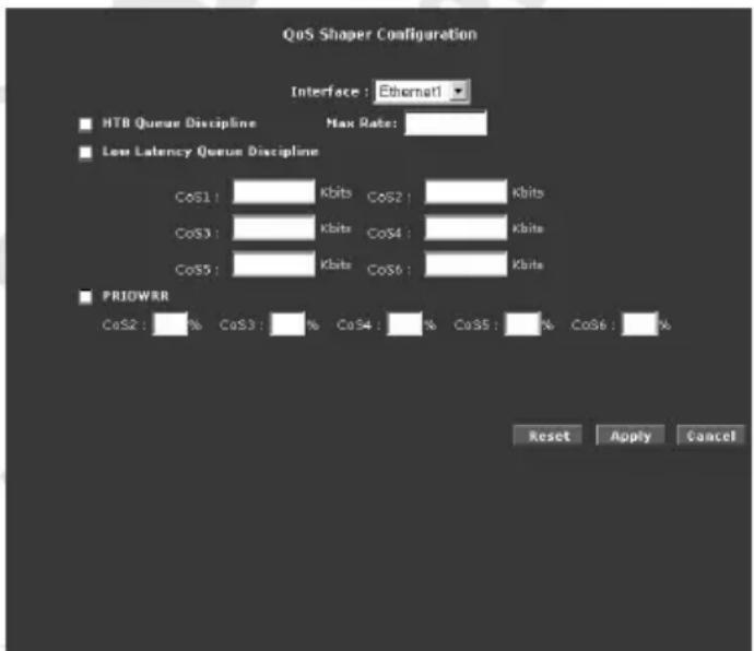
Note: Egress TCA is required if shaper is configured for that interface.
Interface – The selections are WAN/LAN interfaces except WLAN, which does not support Shaper feature. This field needs to be selected before shaper configuration.
Max Rate – This field is applicable for the HTB Queue Discipline and Low Latency Queue Discipline, both are rate-based shaping algorithms.
HTB Queue Discipline – The hierarchical token bucket queue discipline is a rate-based shaping algorithm. This algorithm rate shapes the traffic of a class over a specific interface. All CoSx traffic uses a specific rate to which data will be shaped. For example: If CoS1 is configured to 100Kbps then even if 300Kbps of CoS1 data is being transmitted to the interface only 100Kbps will be sent out.
Low Latency Queue Discipline – This is similar to the above algorithm except that CoS1 is not rate limited. So in the example above CoS1 data is not rate limited to 100Kbps but instead all 300Kbps is transmitted. The side effect is that a misconfigured stream can potentially take all bandwidth.
PRIOWRR – This is a priority based weighted round robin algorithm operating on CoS2-CoS6. CoS1 queues have the highest priority and are not controlled by the WRR algorithm. This is similar to the Low Latency Queue discipline, except that PRIOWRR is packet-based instead of rate-based.
QoS / Policy Routing Configuration
The Policy Routing Configuration enables you to configure policy routing and QoS.
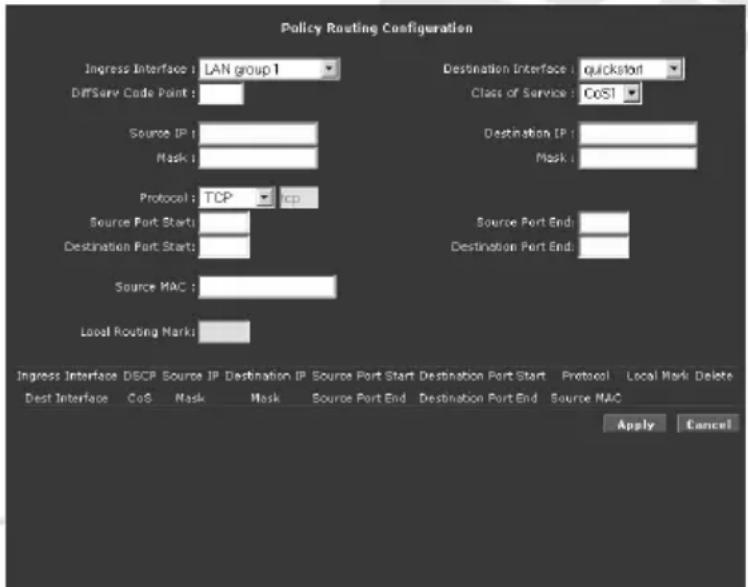
Ingress Interface – The incoming traffic interface for a Policy Routing rule. Selections include LAN interfaces, WAN interfaces, Locally generated (traffic), and not applicable. Examples of Locally generated traffic are: voice packets, packets generated by applications such as DNS, DHCP, etc.
Destination Interface – The outgoing traffic interfaces for a Policy Routing rule. Selections include LAN Interfaces and WAN interfaces.
DiffServ Code Point – The diffServ code point (DSCP) field value ranges from 1 to 255. This field cannot be configured alone, additional fields like IP, Source MAC, and/or Ingress Interface should be configured.
Class of Service – The selections are (in the order of priority): CoS1, CoS2, CoS3, CoS4, CoS5, CoS6, and N/A.
Source IP – The IP address of the traffic source.
Mask – The source IP Netmask. This field is required if the source IP has been entered.
Destination IP – The IP address of the traffic destination.
Mask – The Netmask of the destination. This field is required if the destination IP has been entered.
Protocol – The selections are TCP, UDP, ICMP, Specify, and none. If you choose Specify, you need to enter the protocol number in the box next to the Protocol field. This field cannot be configured alone, additional fields like IP, Source MAC, and/or Ingress Interface should be configured. This field is also required if the source port or destination port has been entered.
Source Port – The source protocol port. You cannot configure this field without entering the protocol first.
Destination Port – The destination protocol port or port range. You cannot configure this field without entering the protocol first.
Source MAC – The MAC address of the traffic source.
Local Routing Mark – This field is enabled only when Locally Generated is selected in the Ingress Interface field. The mark for DNS traffic generated by different applications are described below:
• Dynamic DNS: 0xE1
• Dynamic Proxy: 0xE2
- Web Server: 0xE3
- MSNTP: 0xE4
- DHCP Server: 0xE5
• IP tables Utility: 0xE6
- PPP Deamon: 0xE7
- IP Route: 0xE8
- ATM Library: 0xE9
• NET Tools: 0xEA
- RIP: 0xEB
- RIP v2: 0xEC
- UPNP: 0xEE
- Busybox Utility: 0xEF
- Configuration Manager: 0xF0
- DropBear Utility: 0xF1
- Voice: 0
Currently routing algorithms make decision based on destination address, i.e. only Destination IP address and subnet mask is supported. The Policy Routing page enables you to route packets on the basis of various fields in the packet.
The following fields can be configured for Policy Routing:
- Destination IP address/mask
- Source IP address/mask
- Source MAC address
- Protocol (TCP, UDP, ICMP, etc)
- Source port
- Destination port
- Incoming interface
- DSCP
Routing / Static Routing
If the router is connected to more than one network, you may need to set up a static route between them. A static route is a pre-defined pathway that network information must travel to reach a specific host or network. You can use static routing to allow different IP domain users to access the Internet through the router.
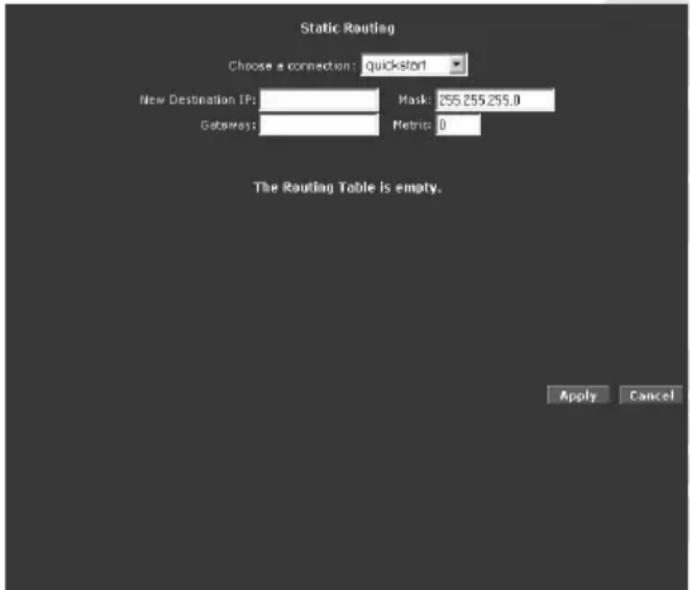
The New Destination IP is the address of the remote LAN network or host to which you want to assign a static route. Enter the IP address of the host for which you wish to create a static route here. For a standard Class C IP domain, the network address is the first three fields of the New Destination IP, while the last field should be 0. The Subnet Mask identifies which portion of an IP address is the network portion, and which portion is the host portion. For a full Class C Subnet, the Subnet Mask is 255.255.255.0. The Gateway IP address should be the IP address of the gateway device that allows for contact between the Gateway and the remote network or host.
Routing / Dynamic Routing
Dynamic Routing allows the router to automatically adjust to physical changes in the network. The router, using the RIP protocol, determines the network packets' route based on the fewest number of hops between the source and the destination. The RIP protocol regularly broadcasts routing information to other routers on the network. The Direction determines the direction that RIP routes will be updated. Selecting In means that the router will only incorporate received RIP information. Selecting Out means that the router will only send out RIP information. Selecting both means that the router will incorporate received RIP information and send out updated RIP information.
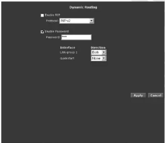
The protocol is dependent upon the entire network. Most networks support RIP v1. If RIP v1 is selected, routing data will be sent in RIP v1 format. If RIP v2 is selected, routing data will be sent in RIP v2 format using subnet broadcasting. If RIP v1 Compatible is selected, routing data will be sent in RIP v2 format using multicasting.
Routing Table
Routing Table displays the information used by routers when making packet-forwarding decisions. Packets are routed according to the packet's destination IP address.
| Destination | Gateway | Genmask | Flags | Metric | Ref | Size | Interface |
| 193.168.1.p | 0.0,0.0 | 255.251.255.0 | Y | 0 | 0 | 0 | bpo |
| 159.0-b.g | 0.0,0.0 | 355.8.0-8 | Y | 1 | 0 | 0 | bcp |
System Password
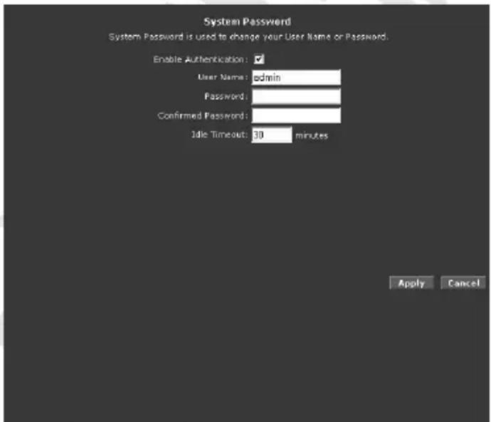
Select Enable Authentication checkbox (strongly recommended), enter User Name and password in Password and Confirmed Password fields and enter Idle Timeout. Use entered User Name and Password when accessing router's Web Interface.
Firmware Upgrade
Note: When updating the firmware, make sure you are using the correct file!
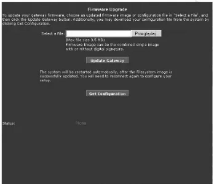
Click Browse and then locate the firmware file. Then click Update Gateway. The update may take a few minutes. Make sure that the power is not turned off during the update process. Once the upgrade is complete the router will reboot. You will need to log back into the router after the firmware upgrade is completed.
Restore to Default
Click OK if you want to reset all settings to factory defaults.
Wireless Tab
Wireless Tab allows you to configure the wireless settings.
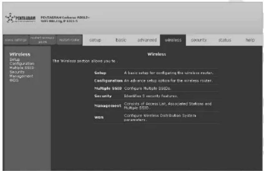
Setup
The default SSID is yournetworkname. SSID is wireless network name for the wireless router. Your wireless client needs this name to establish wireless connection. The wireless setup allows the user to enable or disable the Access Point (AP). Disabling Access Point will prevent the wireless router from emitting any wireless signal.
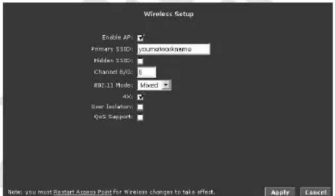
Enable AP – If checked, router will act as wireless access point.
Primary SSID – The SSID is a unique name to identify the router in the Wireless LAN. Wireless clients associating to the router must have the same SSID.
Hidden SSID – Check this box to hide the SSID such that a station can not obtain the SSID through passive scanning. Uncheck to make the SSID visible so a station can obtain the SSID through passive scanning.
Channel B/G – Select channel used by router to create wireless network.
802.11 Mode - Select standard needed to connect to this wireless network: Mixed (B/G), B only, B+ or G only.
User Isolation – Select this checkbox if you want to disable traffic between wireless hosts.
QoS Support – Select this checkbox if you want to apply QoS rules for wireless connection.
Configuration
For users who want to explore the advanced features, you can click on the Advanced button. The options listed can be changed to cater for advance users.
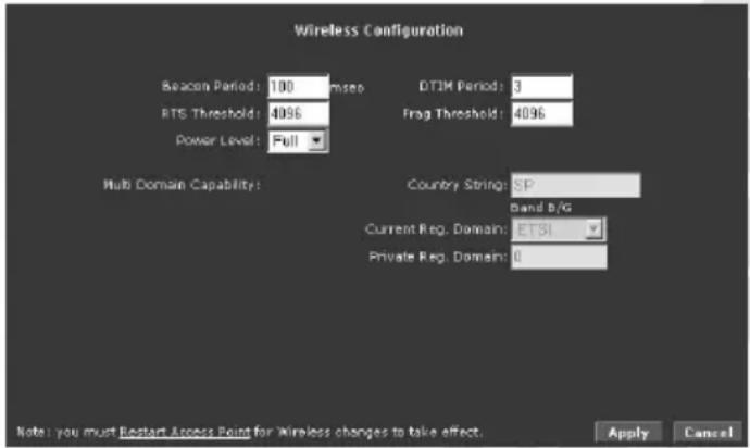
Beacon Interval – The Beacon Interval value indicates the frequency interval of the beacon. Enter a value between 20 and 1000. A beacon is a packet broadcast by the router to synchronize the wireless network.
DTIM Period – This value is between 1 and 255, indicates the interval of the Delivery Traffic Indication Message (DTIM).
RTS Threshold – The RTS (Request To Send) threshold (number of bytes) for enabling RTS/CTS handshake. Data with its frame size larger than this value will perform the RTS/CTS handshake. Set this attribute to be larger than the maximum MSDU (MAC Service Data Unit) size to TURN OFF the RTS/CTS handshake. Set this attribute to ZERO to TURN ON the RTS/CTS handshake.
Frag Threshold - The threshold (number of bytes) for the fragmentation boundary for directed messages. It is the maximum data fragment size that can be sent.
Multi Domain Capability – Multi Domain Capability adds Country Information Element to each Beacon Frame. Country Information Element allows identification of the Regulatory Domain in which router is located. Available Channels and signal Power Levels are included in Country Information Element.
Multiple SSID
Multiple SSID allows you to use a primary and a secondary SSID. The SSID field takes up to 32 alphanumeric characters. Change the VLAN ID to a number different from zero (between 1 to 4095).
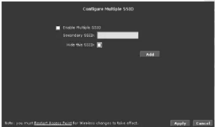
Enable Multiple SSID – Check to enable Multi SSID function.
To add Secondary SSID, enter its name in Secondary SSID field, check Hide SSID box if you want it to be hidden and click Add. All secondary SSID's will be displayed on the list below. To delete SSID select appropriate checkbox in Delete column. You can add up to 3 secondary SSID's.
Wireless Security
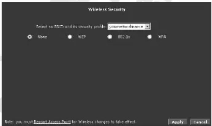
It is important for user to enforce security in wireless LAN environment. This is to prevent unauthorized wireless users from accessing your router. By default, None is selected.
• WEP
WEP is a security protocol for WLAN. WEP provides security by encrypting the data that is sent over the WLAN. You can configure up to 4 sets of keys for your wireless client. The router supports three levels of WEP encryption: 64-bit, 128-bit and 256-bit. With WEP, the receiving station must use the same key for decryption. Each radio network interface card (NIC) and router must be manually to use the same key.
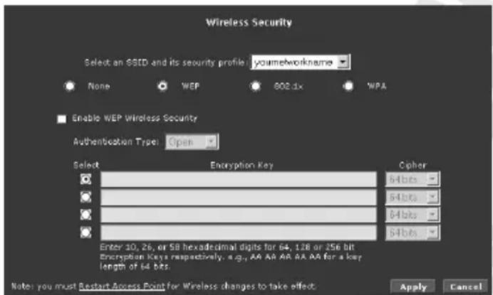
To use WEP encryption select Enable WEP Wireless Security checkbox, select Authentication Type from list, select which Encryption Key will be used, select its strength (Cipher) and enter Encryption Key: any 10 (Cipher 64 bits), 26 (Cipher 128 bits) or 58 (Cipher 256 bits) hexadecimal digits ("0-9", "A-F").
• 802.1x
802.1x is a security protocol for WLAN. It is a port-based network access control that keeps the network port disconnected until authentication is completed. 802.1x is based on extensible authentication protocol (EAP). EAP messages from the authenticator to the authentication server typically use the remote authentication dial-in user service (RADIUS) protocol.
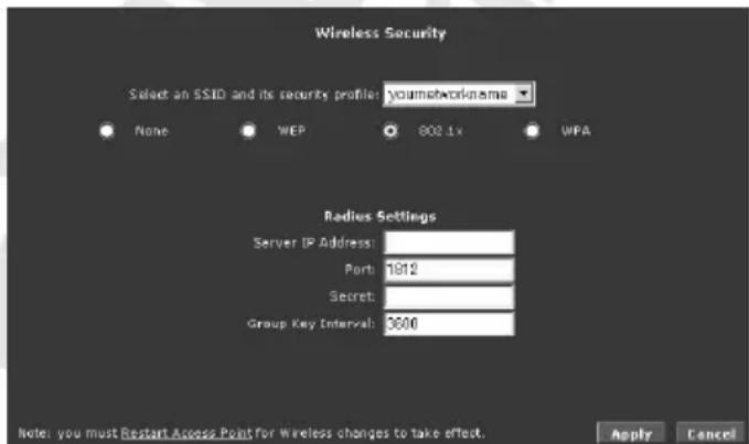
Server IP Address – Enter IP Address of RADIUS authentication server.
Port – Enter Authentication port on RADIUS server.
Secret – Enter Shared Secret used by RADIUS server.
Group Key Interval – Enter time interval in which the group key is automatically changed across the whole network.
• WPA
WPA is the short term for WiFi Protected Access. WPA is an industry-supported, pre-standard version of 802.11i that utilizes the Temporal Key Integrity Protocol (TKIP), which fixes the problems of WEP, which includes using dynamic keys. WPA uses a sophisticated key hierarchy that generates new encryption keys each time a mobile device establishes itself with an Access Point. Protocols including 802.1X, EAP, and RADIUS are used for strong authentication. Like WEP, keys can still be entered manually (pre-shared keys); however, using a RADIUS authentication server provides automatic key generation and enterprise-wide authentication. WPA uses temporal key integrity protocol (TKIP) for data encryption. WPA2, also known as 802.11i, uses advanced encryption standard counter mode CBC-MAC protocol (AES-CCMP) for data encryption.
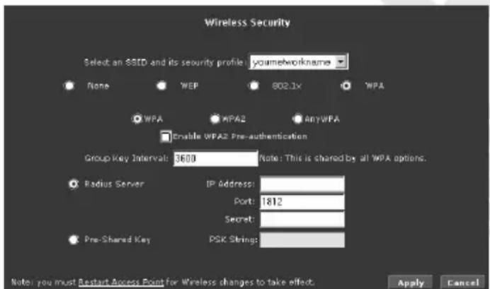
WPA / WPA2 / AnyWPA – select version of WPA authentication that will be used to secure this wireless network.
Enable WPA2 Pre-authentication – Only for WPA2/AnyWPA. Pre-authenticacion keeps the network port disconnected until authentication is completed.
Group Key Interval – Enter time interval in which the group key is automatically changed across the whole network.
Radius Server – Select this option to use RADIUS server for WPA authentication. Enter IP Address, Authentication Port and Shared Secret used by RADIUS server.
Pre-Shared Key – Select this option to use Pre-Shared Key (PSK) for WPA authentication. Both the router and the wireless clients must use the same Pre-Shared Key for data transmission (similar to WEP Keys).
Wireless Management
The wireless management function gives another level of security to your router. It allows you to permit or ban devices by entering the MAC address or selecting devices that are currently connected.
- Access List
This feature permits you to allow or ban wireless clients by using the MAC address.
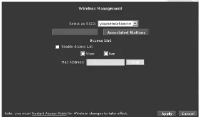
Enable Access List – Select this checkbox to enable Access List.
Allow – Only listed clients will be allowed to connect to router. Not listed clients will be banned from connecting to router.
Ban – Only listed client will be banned from connecting to router. Not listed client will be allowed to connect to router.
• Associated Stations
Clients connected to the wireless router are displayed in this page.
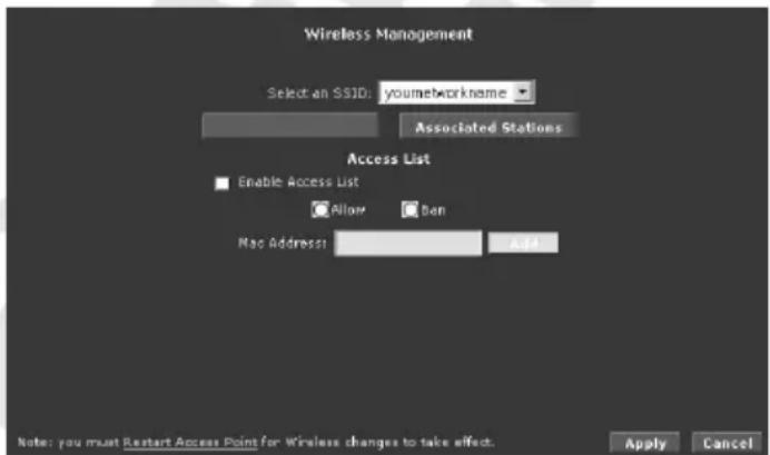
Select checkbox in Ban Station column to ban this client.
Wireless Distribution System
Wireless distribution system (WDS) is a system that interconnects BSS to build a premise wide network. WDS network allows users of mobile equipment to roam and stay connected to the available network resources.
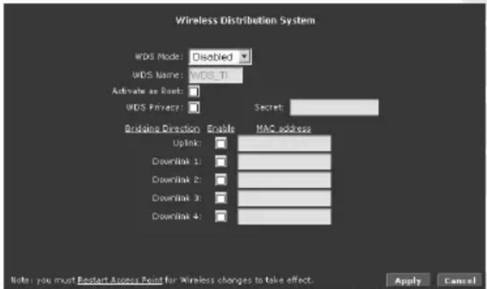
WDS Mode – The following WDS mode are available:
- Bridge – In Bridge mode, the Access Point basic service set (BSS) service is enabled.
- Repeater – In Repeater mode, the Access Point BSS is disabled when connection to the upper layer Access Point is established
- Crude – In Crude mode, the Access Point BSS is always enabled; however the links between Router are configured statically and are not maintained.
- Disabled (Default) – WDS inactive.
In both Bridge and Repeater modes, WDS uses management protocol to establish and maintain links between Router.
WDS Name – The WDS name is used to identify WDS network. The field takes up to eight characters. Two or more WDS networks may exist in the same area.
Activate as Root – This field must be checked for the root device in WDS hierarchy. Only one WDS root device may exist in WDS network. This field is not applicable for Crude mode.
WDS Privacy – Checking this field commands WDS manager to use a secured connection between Router in the WDS network. Security settings must be the same in all Router in the WDS network. Note: WDS privacy is not supported in Crude mode.
Secret – The 32-character alphanumeric privacy key.
Uplink Connection – The BSS ID of the upper device in the WDS hierarchy. This uplink cannot be configured if root is enabled.
Downlink Connection – The BSS ID of the lower device in the WDS hierarchy connected to this Access Point. Up to four downlinks can be configured.
Security Tab
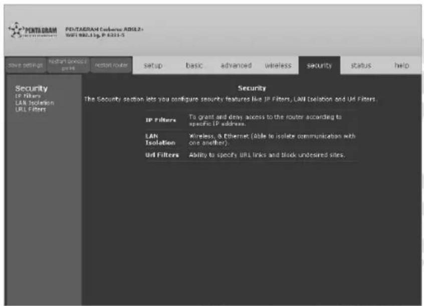
IP Filters
IP filtering allows you to block specific applications/services based on the IP address of the LAN device. In this page, you can block specific traffic (for example, block web access) or any traffic from a host on your local network.
A database of predefined IP filters allows you to apply one or more filtering rules to one or more members of a defined LAN group. You can view the rules associated with a predefined filter and add the available rules for a given category. You can also create, edit, or delete your own IP filter rules.
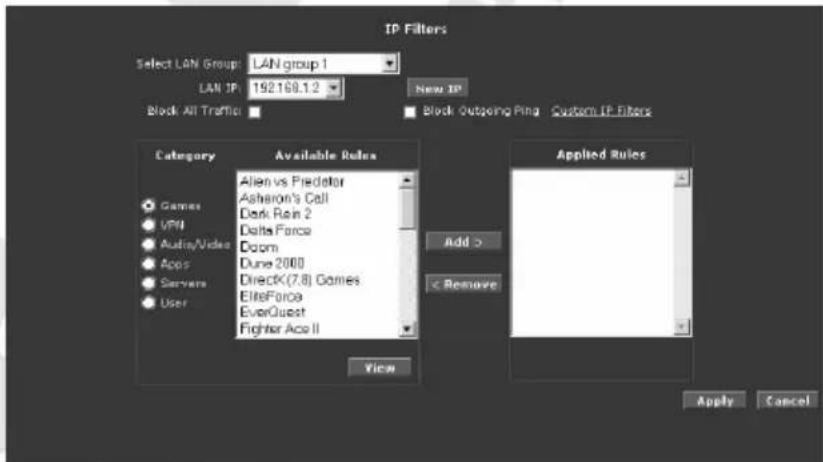
Select LAN Group / LAN IP – Select Group and then enter LAN IP address of host which rules you want to configure. Select Any in LAN IP to set rules to all hosts in selected group.
New IP – Opens LAN Clients page where you can add new static IP address (refer to LAN / LAN Clients section for more details).
Block All Traffic – Select this checkbox to block all network traffic for selected host..
Block Outgoing Ping – Select this checkbox to block Ping packets from selected host.
Custom IP Filters – Opens Custom IP Filters page where you can create more advanced rules.
Cerberus ADSL2+ Wi-Fi (P 6331-5)
Category – Rules are grouped based on their purpose. You can create your own rules in User Category.
Available Rules – List of all available rules in selected category. Select rule and click Add to add this rule to Applied Rules list.
Applied Rules – List of all active rules for selected host. Select rule and click Remove to remove this rule from Applied Rules list.
New – Active only under User category. Opens Rule Management page.
View – Opens Rule Management page with details of selected rule.
Delete – Active only under User category. Use this button to delete selected rule.
You can open below pages from IP Filters page:
- Rule Management (New Rule)
The Rule Management page allows you to create new rules. To create new rule enter Rule Name, Protocol, Port Start, Port End, and Port Map, and then click Apply.
Created rules can be also used to set Port Forwarding (Advanced Tab).
- Custom IP Filters
The Custom IP Filters page allows you to create up to 15 custom IP Filters entries to block specific services or applications.
LAN Isolation
LAN isolation allows you to disable the flow of packets between two LAN groups. This allows you to secure information in private portions of the LAN from other publicly accessible LAN segments.
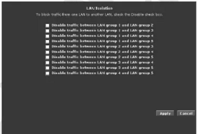
Select appropriate checkbox to disable traffic between two LAN groups.
URL Filters
URL Filtering allows the router to block access to certain websites by examining its URL, a text string describing a unique location on the Internet. If the URL contains a blocked keyword, then access to that website will be denied.
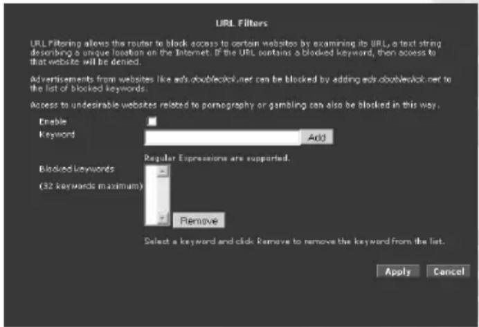
Enable – Select this checkbox to enable URL Filter.
Keyword – Enter keyword you want to block and click Add.
Blocked keywords – List of all blocked keywords. Select a keyword and click Remove to remove the keyword from the list.
Status Tab
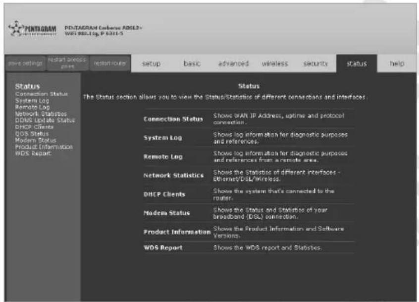
The Status Tab provides the status for different connections or interfaces.
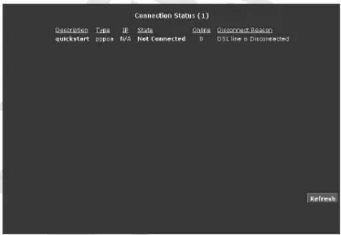
Connection Status
Connection Status displays the type of protocol, the WAN IP address, the connection state and the duration of your Internet connection.
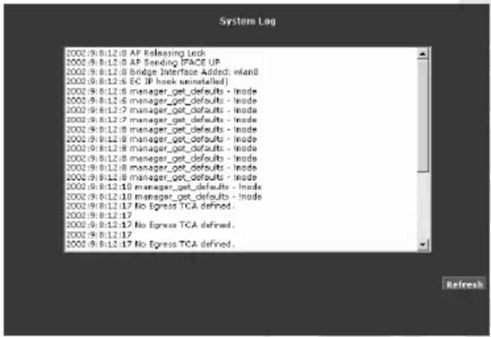
System Log
System Log displays the router log. Depending on the severity level, the information log will generate log reports to a remote host if remote logging is enabled.
Remote Log
Remote Log allows you to forward all logged information to one (or more) remote computer. The type of information forwarded to the remote computer depends on the Log level. Each log message belongs to a certain log level, which indicates the severity of the event.
When you configure remote logging, you must specify a severity level. Log messages that are rated at that level or higher are sent to the log server and can be viewed using the server log application, which can be downloaded from the web.
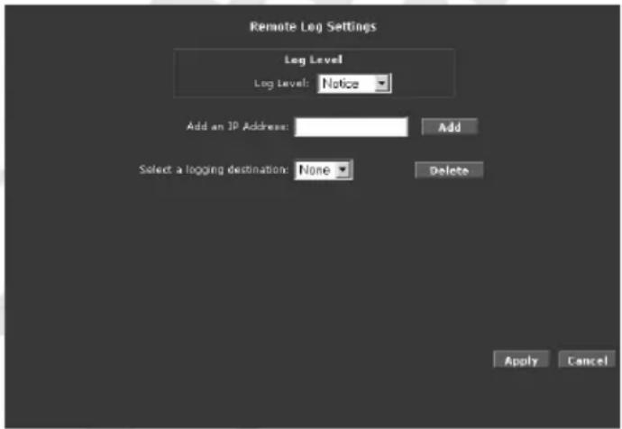
To enable remote logging:
-
Select a Log Level. There are 8 log levels listed below in order of severity.
-
Panic – System panic or other condition that causes the router to stop functioning.
- Alert – Conditions that require immediate correction, such as a corrupted system database.
• Critical – Critical conditions such as hard drive errors. Page 111 of 121 - Error – Error conditions that generally have less serious consequences than errors in the emergency, alert, and critical levels.
- Warning – Conditions that warrant monitoring.
- Notice (Default) – Conditions that are not errors but might warrant special handling.
- Info – Events or non-error conditions of interest.
- Debug – Software debugging message. Specify this level only when directed by a technical support representative.
- In Add an IP Address field enter the IP Address where the log will be sent to and then click Add.
- Click Apply. The IP address will appear in the Select a logging destination drop-down menu.
To disable a remote log select the IP address to be deleted from the Select a logging destination drop-down menu and click Delete.
Network Statistics
The Ethernet and DSL line statuses are displayed in this page.
• Network Statistics – Ethernet
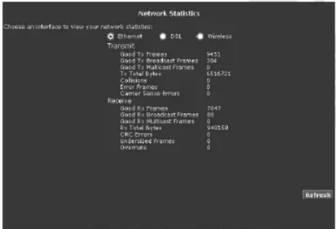
• Network Statistics – DSL
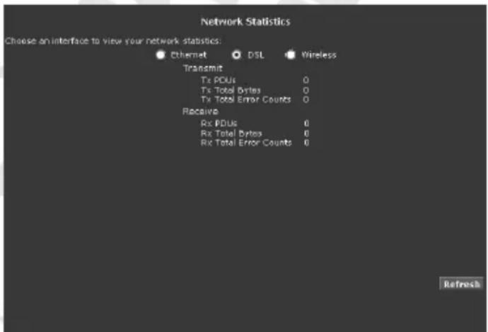
• Network Statistics – Wireless
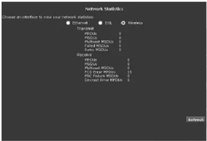
DDNS Update Status
DDNS Update Status displays the WAN connection status. By default, DDNS is disabled. When the DDNS is enabled, the DDNS client updates every time the router gets a new IP address.
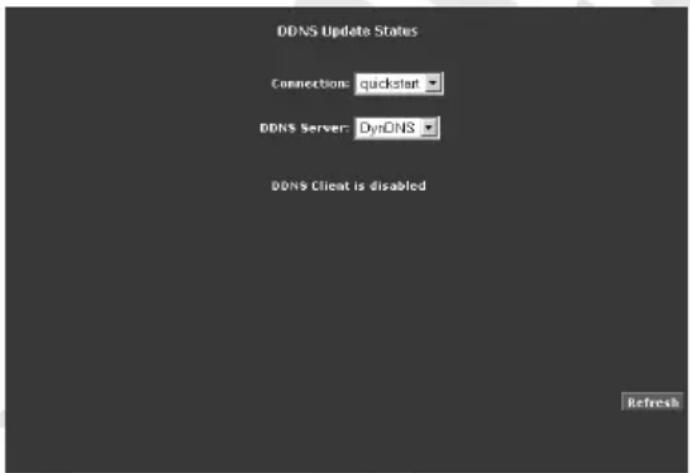
DHCP Clients
DHCP Clients displays the MAC address, IP address, host name, and lease time.
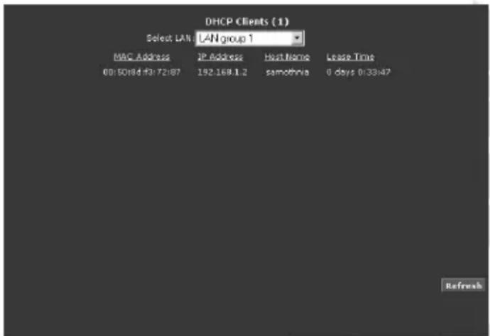
QoS Status
This page displays the Quality of Service and the packet statistics.
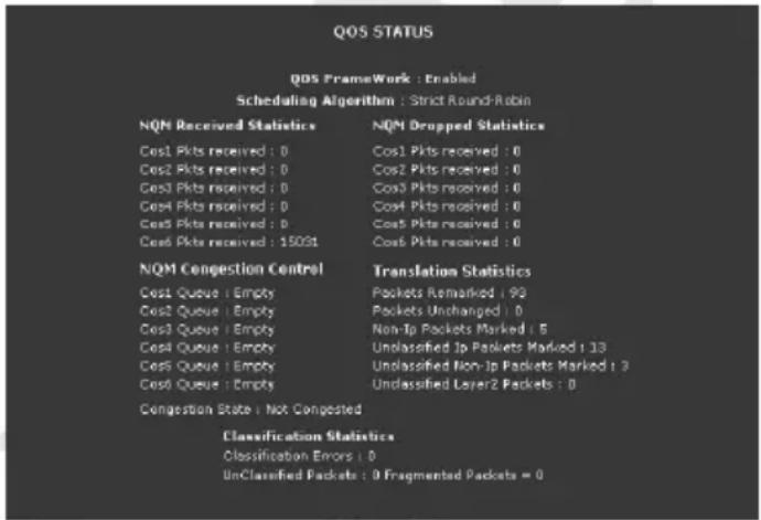
Modem Status
This page displays the model status.
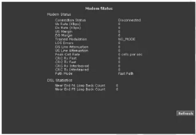
Product Information
This page displays the product information and software versions.
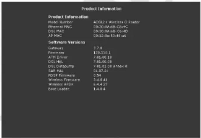
WDS Report
This page displays the WDS-related wireless activities: WDS configuration and states, WDS management statistics, WDS database.
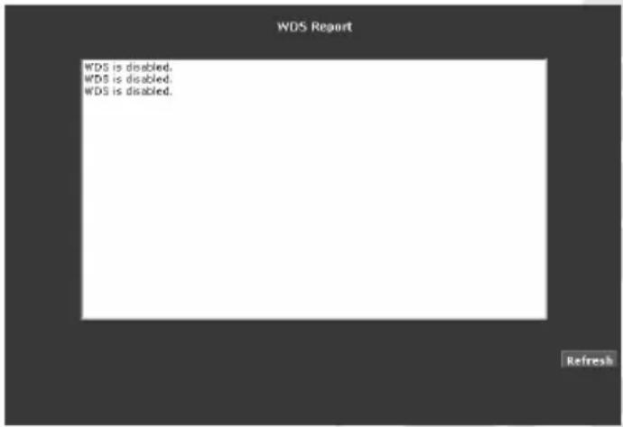
Help Tab
The Help Tab provides documentation for various topics like Firewall, Bridge Filters, LAN Clients, LAN Group Configuration, PPP Configuration, UPnP, IP QoS, and Routing Information Protocol.
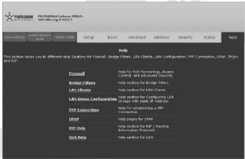
Troubleshooting
If the router is not function properly, first check this session for simple troubleshooting before contacting your Internet service provider (ISP) for support.
Using LEDs to Diagnose Problems
The LEDs are useful aides for finding possible problem causes.
Power LED
The POWER LED on the front panel does not light up.:
- Make sure that the power adaptor is connected to the router and plugged in to an appropriate power source. Use only the supplied power adaptor;
- Check that the router and the power source are both turned on and the router is receiving sufficient power;
- Turn the router off and on;
- If the error persists, you may have a hardware problem. In this case, you should contact your vendor.
LAN LED
The LAN LED on the front panel does not light up.:
- Check the Ethernet cable connections between your router and the computer or hub;
- Check for faulty Ethernet cables;
- Make sure your computer's Ethernet card is working properly;
- If these steps fail to correct the problem, contact your local distributor for assistance.
ADSL LED
The ADSL LED on the front panel does not light up:
- Check the telephone wire and connections between the router ADSL port and the wall jack;
- Make sure that the telephone company has checked your phone line and set it up for ADSL service;
- Reset your ADSL line to reinitialize your link to the DSLAM;
- If these steps fail to correct the problem, contact your local distributor for assistance.
Problems with the Web Interface
I cannot access the web Interface:
- Make sure you are using the correct IP address of the router. Check the IP address of the router;
- Make sure that there is not a console session running;
- Check that you have enabled web service access. If you have configured a secured client IP address, your computer's IP address must match it. Refer to the chapter on remote management for details;
-
For WAN access, you must configure remote management to allow server access from the WAN (or all);
-
Your computer's and the router's IP addresses must be on the same subnet for LAN access;
- If you changed the router's LAN IP address, then enter the new one as the URL;
- Remove any filters in LAN or WAN that block web service.
The web Interface does not display properly:
- Make sure you are using Internet Explorer 5.0 (or compatible) and later versions;
- Delete the temporary web files and log in again.
Problems with the Login Username and Password
I forgot my login username and/or password:
- The default username is "admin". The default password is "trendchip". The Password and Username fields are case-sensitive. Make sure that you enter the correct password and username using the proper casing;
- Press the DEFAULT button for five seconds, and then release it. When the ADSL LED begins to blink, the defaults have been restored and the router restarts;
Problems with LAN Interface
I cannot access the router from the LAN or ping any computer on the LAN:
- Check the Ethernet LEDs on the front panel. A LAN LED should be on for a port that has a PC connected. If it is off, check the cables between your router and the PC. Make sure you have uninstalled any software firewall for troubleshooting;
- Make sure that the IP address and the subnet mask is consistent between the router and the workstation.
Problems with WAN Interface
Initialization of the ADSL connection failed:
- Check the cable connections between the ADSL port and the wall jack. The ADSL LED on the front panel of the router should be on;
- Check that your VPI, VCI, type of encapsulation and type of multiplexing settings are the same as what you collected from your telephone company and ISP;
- Restart the router. If you still have problems, you may need to verify your VPI, VCI, type of encapsulation and type of multiplexing settings with the telephone company and ISP.
I cannot get a WAN IP address from the ISP:
- Ensure that all other devices connected to the same telephone line as your router (e.g. telephones, fax machines, analogue modems) have a line filter connected between them and the wall socket (unless your are using a Central Splitter or Central Filter installed by the qualified and licensed electrician), and ensure that all line filters are correctly installed and right way around;
- Missing line filters or line filters installed the wrong way around can cause problems with your ADSL connection, including causing frequent disconnects.
Frequent loss of ADSL line sync (disconnections):
- The ISP provides the WAN IP address after authenticating you. Authentication may be through the user name and password, the MAC address or the host name;
- The username and password apply to PPPoE and PPPoA encapsulation only. Make sure that you have entered the correct Service Type, User Name and Password (be sure to use the correct casing).
Problems with the Internet Access
I cannot access the Internet:
- Make sure the router is turned on and connected to the network;
- If the ADSL LED is off, refer to Section ADSL LED of this troubleshooting;
- Verify your WAN settings;
- Make sure you entered the correct user name and password;
- For wireless stations, check that both the router and wireless station(s) are using the same ESSID, channel and WEP keys (if WEP encryption is activated).
Internet connection disconnects:
- If you use PPPoA or PPPoE encapsulation, check the idle time-out setting;
- Contact your ISP.
If you have any troubles to configure or setup this ADSL Ethernet Router, please feel free to contact us.
- Installation and User's Manual
- PENTAGRAM Cerberus
- ADSL2+ Wi-Fi
- (P 6331-5)
- INDEX
- Introduction
- Features
- Package Contents
- Product Overview
- Important Notes
- Front Panel
- Back Panel
- Label Used for...
- Default Settings
- Resetting router
- Connecting Cerberus to Computer.
- Connecting via Ethernet Port (Ethernet Card)
- Connecting via WLAN Interface (Wireless Card)
- Configure TCP/IP
- Windows Vista
- Windows 2000/XP
- Windows 95/98/Me
- Configure router via web browser
- Login
- Navigation
- Buttons
- Commands
- Tabs
- Glossary:
- Setup Tab
- Internet Login Account Setting
- Wireless LAN Configuration
- Wireless LAN Security
- System Password
- Summary
- Basic Tab
- Home
- Quick Start
- LAN configuration
- Diagnostics
- - Ping Test
- • Full Modem Test
- Advanced Tab
- WAN / New Connection
- PVC Settings
- Selected Type dependent settings
- - PPP Settings (PPPoA/PPPoE)
- - Static Settings
- - DHCP Settings
- - Bridge Settings
- - CLIP
- WAN / ADSL Modulation
- WAN / Connection Scan
- LAN / LAN Configuration
- • LAN Group x configuration
- Unmanaged
- Obtain IP address automatically
- PPP IP Address
- Use the following Static IP address
- LAN / LAN Clients
- Application / UPnP
- Application / SNTP
- Application / SNMP
- Application / IGMP Proxy
- Application / TR-068 WAN Access
- Application / TR-069
- Application / NAT Services
- Application / DNS Proxy
- Application / Dynamic DNS Client
- Application / Easy Connect Configuration
- Application / Port Triggering
- Application / Port Forwarding
- • Rule Management (New Rule)
- • DMZ
- - Custom Port Forwarding
- Application / Bridge Filters
- Application / Web Access Control
- Application / SSH Access Control
- QoS
- QoS / Egress
- - No Egress Mode
- - Layer 2
- - Layer 3
- QoS / Ingress
- - Untrusted Mode
- Notes:
- - Static
- QoS / QoS Shaper Configuration
- QoS / Policy Routing Configuration
- Routing / Static Routing
- Routing / Dynamic Routing
- Routing Table
- Firmware Upgrade
- Restore to Default
- Wireless Tab
- Setup
- Configuration
- Multiple SSID
- Wireless Security
- • WEP
- • 802.1x
- • WPA
- Wireless Management
- - Access List
- • Associated Stations
- Wireless Distribution System
- Security Tab
- IP Filters
- Cerberus ADSL2+ Wi-Fi (P 6331-5)
- - Rule Management (New Rule)
- - Custom IP Filters
- LAN Isolation
- URL Filters
- Status Tab
- Connection Status
- System Log
- Remote Log
- Network Statistics
- • Network Statistics – Wireless
- DDNS Update Status
- DHCP Clients
- QoS Status
- Modem Status
- Product Information
- WDS Report
- Help Tab
- Troubleshooting
- Using LEDs to Diagnose Problems
- Power LED
- LAN LED
- ADSL LED
- Problems with the Web Interface
- Problems with the Login Username and Password
- Problems with LAN Interface
- Problems with WAN Interface
- Problems with the Internet Access
Brand : Pentagram
Model : Cerberus P6331-5
Category : Router