Cerberus ADSL Wi-Fi Lite - Router Pentagram - Free user manual and instructions
Find the device manual for free Cerberus ADSL Wi-Fi Lite Pentagram in PDF.


| Product Type | ADSL Wi-Fi Router |
| Brand | Pentagram |
| Model | Cerberus ADSL Wi-Fi Lite |
| Dimensions (W x D x H) | 160 x 110 x 30 mm |
| Weight | 250 g |
| Power Supply | 12V DC, 1A |
| ADSL Standard | ADSL2+ (up to 24 Mbps) |
| Wi-Fi Standard | IEEE 802.11b/g/n (up to 150 Mbps) |
| Ethernet Ports | 4 x 10/100 Mbps LAN |
| USB Port | 1 x USB 2.0 for file sharing |
| Security | WPA/WPA2-PSK, WEP 64/128 bit, SPI Firewall |
| Wireless Range | Up to 100 m indoors |
| Operating Temperature | 0°C to 40°C |
| Humidity | 10% to 90% non-condensing |
| LED Indicators | Power, DSL, Internet, LAN, WLAN, USB |
| Antenna | 2 x 5 dBi external detachable antennas |
| VPN Support | PPTP, L2TP, IPSec passthrough |
| Management | Web-based GUI, CLI via telnet |
| Warranty | 2 years |
| Package Contents | Router, power adapter, RJ-11 cable, RJ-45 cable, manual |
Frequently Asked Questions - Cerberus ADSL Wi-Fi Lite Pentagram
User questions about Cerberus ADSL Wi-Fi Lite Pentagram
0 question about this device. Answer the ones you know or ask your own.
Ask a new question about this device
Download the instructions for your Router in PDF format for free! Find your manual Cerberus ADSL Wi-Fi Lite - Pentagram and take your electronic device back in hand. On this page are published all the documents necessary for the use of your device. Cerberus ADSL Wi-Fi Lite by Pentagram.
USER MANUAL Cerberus ADSL Wi-Fi Lite Pentagram
Installation and User's Manual
PENTAGRAM Cerberus ADSL Wi-Fi Lite
NOTE! Any information and technical data are subject to change without prior notification and/or indication in this manual.
INDEX
INTRODUCTION 5
PACKAGE CONTENTS.... 5
FEATURES....6
PRODUCT OVERVIEW....7
IMPORTANT NOTES....7
FRONT LEDS 7
THE REAR PORTS....8
DEFAULT SETTINGS....8
RESETTING ROUTER 9
CONNECTING CERBERUS TO COMPUTER....9
CONFIGURE TCP/IP 9
CONFIGURE ROUTER VIA WEB BROWSER.... 13
LOGIN....13
NAVIGATION....14
QUICK START WIZARD.... 15
INTERFACE SETUP TAB....20
ADVANCED SETUP TAB 29
ACCESS MANAGEMENT TAB.... 37
MAINTENANCE TAB.... 42
STATUS TAB......46
HELP TAB....50
TROUBLESHOOTING....51
USING LEDS TO DIAGNOSE PROBLEMS 51
PROBLEMS WITH THE WEB INTERFACE 51
PROBLEMS WITH THE LOGIN USERNAME AND PASSWORD 52
PROBLEMS WITH LAN INTERFACE.... 52
PROBLEMS WITH WAN INTERFACE 52
PROBLEMS WITH THE INTERNET ACCESS 53
Introduction
Thank you for purchasing the Cerberus ADSL Wi-Fi Lite ADSL2+ Modem/Router by PENTAGRAM. Your new router is an all-in-one unit that combines an ADSL modem, ADSL router and Ethernet network switch to provide everything you need to get the machines on your network connected to the Internet over an ADSL broadband connection.
The Cerberus ADSL Wi-Fi Lite router complies with ADSL2+ standards for deployment worldwide and supports downstream rates of up to 24 Mbps and upstream rates of up to 1 Mbps. Designed for small office, home office and residential users, the router enables even faster Internet connections. You can enjoy ADSL services and broadband multimedia applications such as interactive gaming, video streaming and real-time audio much easier and faster than ever before.
Your new router also serves as an Internet firewall, protecting your network from access by outside users. Not only does it provide a natural firewall function with Network Address Translation (NAT), it also provides rich firewall features to secure your network. All incoming data packets are monitored and filtered. You can also configure your new router to block internal users from accessing the Internet.
The Integrated DHCP (Dynamic Host Control Protocol) client and server services allow multiple users to get IP addresses automatically when the router boots up. Simply set local machines as a DHCP client to accept a dynamically assigned IP address from the DHCP server and reboot. Each time a local machine is powered up; the router recognizes it and assigns an IP address to instantly connect it to the LAN.
For advanced users, Virtual Service (port forwarding) functions allow the product to provide limited visibility to local machines with specific services for outside users. You can set an ISP (Internet Service Provider) provided IP address on the Cerberus ADSL Wi-Fi Lite and then you can reroute specific services to individual computers on your local network. For instance, a dedicated web server can be connected to the Internet via the router and then incoming requests for web pages that are received by the router can be rerouted to your dedicated local web server, even though the server now has a different IP address.
Virtual Server can also be used to re-task services to multiple servers. For instance, you can set the router to allow separated FTP, Web, and Multiplayer game servers to share the same Internet-visible IP address while still protecting the servers and LAN users from hackers.
Package Contents
- PENTAGRAM Cerberus ADSL Wi-Fi Lite
- Power adapter 12 V, 1 A
- Ethernet cable (RJ-45)
- Telephone cable (RJ-11)
- CD
- Quick Installation Guide
Features
- A 4-port 10/100Mbps fast Ethernet switch is built-in with automatic switching between MDI and MDI-X for 10Base-T and 100Base-TX ports, with auto detection allowing you to use either straight or cross-over Ethernet cables.
- With built-in 802.11g access point for extending the communication media to WLAN while providing the WEP and WPA/WPA-TKIP/PSK for securing your wireless networks.
- Network Address Translation (NAT) allows multiple users to access outside resources such as the Internet simultaneously with one IP address/one Internet access account. Many application layer gateways (ALG) are supported such as web browser, ICQ, FTP, Telnet, E-mail, News, Net2phone, Ping, NetMeeting, IP phone and others.
- Universal Plug and Play (UPnP) and UPnP NAT Traversal: This protocol is used to enable simple and robust connectivity among stand-alone devices and PCs from many different vendors, and it makes setting up a network simple and affordable. UPnP architecture leverages TCP/IP and the Web to enable proximity networking in addition to control and data transfer among networked devices. With this feature enabled, you can seamlessly connect to Net Meeting or MSN Messenger.
- The Dynamic DNS service allows you to alias a dynamic IP address to a static hostname. This dynamic IP address is the WAN IP address. To use the service, you must first apply for an account from a DDNS service such as http://www.dyndns.org.
- The Cerberus ADSL2 Wi-Fi Lite provides an embedded PPPoE client function to establish a connection. You get greater access speed without changing the operation concept, while sharing the same ISP account and paying for one access account. No PPPoE client software is required for the local computer. Automatic Reconnect and Disconnect Timeout (Idle Timer) functions are also provided.
- Virtual Server: You can specify which services are visible to outside users. The router detects an incoming service request and forwards it to the specific local computer for handling. For example, you can assign a PC in a LAN to act as a Web server inside and expose it to the outside network. Outside users can browse inside the web server directly while it is protected by NAT. A DMZ host setting is also provided for local computers exposed to the outside Internet network.
- Dynamic Host Configuration Protocol (DHCP) Client and Server: On a WAN site, the DHCP client obtains an IP address from the Internet Service Provider (ISP) automatically. On a LAN site, the DHCP server allocates a range of client IP addresses, including subnet masks and DNS IP addresses and distributes them to local computers. This provides an easy way to manage the local IP network.
- Static and RIP1/2 Routing: An easy static routing table or RIP1/2 routing protocol supports routing capability.
- SNMP (Simple Network Management Protocol): SNMP allows convenient remote management of the router.
-
Web-based GUI: A web-based GUI offers easy configuration and management. User-friendly and with on-line help, it also supports remote management capability for remote users to configure and manage this product.
-
Firmware Upgradeable: You can upgrade the router with the latest firmware through its web-based GUI.
- High Speed Internet Access: downstream rates of up to 24Mbps and upstream rates of up to 1Mbps. Cerberus ADSL Wi-Fi Lite is compliant with the following standards: ANSI T1.413 issue 2, ITU-T G.992.1 (G.dmt), ITU-T G.992.2 (G.lite), G.994.1 (G.hs, Multimode), ITU-T G.992.3 (ADSL2 G.dmt.bis), ITU-T G.992.4 (ADSL2 G.lite.bis), ITU-T G.992.5 (ADSL2+; Annex A, I, J, L & M), Reach Extended ADSL (RE ADSL).
- Multi-Protocol to Establish a Connection: The router supports PPPoA (RFC 2364 - PPP over ATM Adaptation Layer 5), RFC 1483/2684 encapsulation over ATM (bridged or routed), PPP over Ethernet (RFC 2516) and IPoA (RFC1577) to establish a connection with an ISP. The router also supports VC-based and LLC-based multiplexing.
Product Overview
Important Notes


- Do not use the router in high humidity or high temperatures.
- Do not use the same power source for the router as other equipment.
- Do not open or repair the case yourself. If the router is too hot, turn off the power immediately and have it repaired at a qualified service center.
- Avoid using this product and all accessories outdoors.
- Place the router on a stable surface.
- Only use the power adapter that comes with the package. Using a different voltage rating power adaptor may damage the router.
Front LEDs

| LED Description | ||
| 1 | PWR | Lights when the power is ON. |
| 2 | WLAN | Lit green when the wireless connection is established.Flashes when sending/receiving data. |
| 3 | LAN1 | Steady glow when connected to an Ethernet device.Glows green for 100Mbps; Orange for 10Mbps.Blinking light when data is Transmitted / Received. |
| 4 | LAN2 | |
| 5 | LAN3 | |
| 6 | LAN4 | |
| 7 | ADSL | Lights when successfully connected to an ADSL DSLAMBlinking when router is trying to connect to a DSLAM. |
The Rear Ports

| LINE (RJ-11) | Connect the supplied RJ-11 (telephone) cable to this port when connecting to the ADSL/telephone network. |
| LAN (RJ-45) | Connect a UTP Ethernet cable (Cat-5 or Cat-5e) to one of the four LAN ports when connecting to a PC or an office/home network of 10Mbps or 100Mbps. |
| DEFAULT | After the router is powered on, press this recessed button using the end of paper clip or other small pointed object to reset the router or to restore it to factory default settings. |
| PWR | Connect the supplied power adapter to this jack. |
| ON/OFF | Power switch button. |
Default Settings
Before changing configuration familiarize yourself with these default settings.
| LAN/WLAN Ports | |
| IP Address 10.0.0.2 | |
| Subnet Mask 255.0.0.0 | |
| DHCP Server Enabled | |
| DHCP Server IP Address Pool | 12 IP addresses from 10.0.0.2 |
| IP Address Lease Time 259200 seconds (72 hours) | |
| User Name | admin |
| Password | trendchip |
If you ever forget the password to log in, you may need to reset router to restore the factory default settings. This procedure is described on the next page.
Resetting router
- Turn router on and wait for ADSL LED to lit or start blinking.
- Press and hold DEFAULT button on the back panel of router for 5-10 seconds and then release it.
- After reset LEDs will return to their normal behavior and all settings will be reset to their default value. You can login web configurator using default username and password: admin / trenchip.
Connecting Cerberus to Computer.
Cerberus can be connected to computer via Ethernet or WLAN:
Connecting via Ethernet Port (Ethernet Card)
If there is an available LAN card present on your PC, you just simply connect ADSL router and PC through the Ethernet cable. Once you establish Internet connection, you could browse the Web through the Ethernet cable.
Connecting via WLAN Interface (Wireless Card)
To connect PC to Cerberus via WLAN, Wireless Adapter must be properly installed and configured and both router and PC must be in the same subnet.
Configure TCP/IP
This part will help you to configure your computer to communicate with Cerberus ADSL Wi-Fi Lite router properly. Computer must be either equipped with network adapter connected directly to Cerberus ADSL Wi-Fi Lite router or wireless network adapter (compatible with Wi-Fi 802.11b/g standard). Wireless network adapter must have the same session ID (ESSID) and establish connection with the network created by router. You can also connect to Cerberus ADSL Wi-Fi Lite router via network hub/switch. Default IP address of the router is 10.0.0.2 and subnet mask is 255.0.0.0. Fastest and easiest method to configure your computer is to obtain an IP address automatically from router's DHCP server.
Make sure that TCP/IP protocol and network adapter are installed on your computer.
Windows 2000/XP
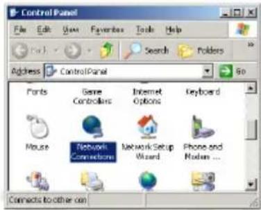
- Click Start → Settings → Control Panel. Double-click the Network Connections (2000/XP Classic view) or click Network and Internet Connections and then Network Connections (XP Default view).
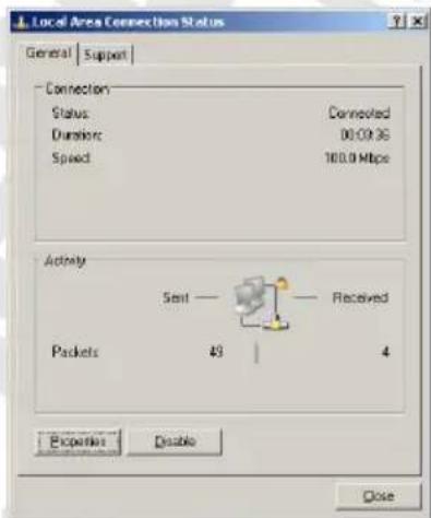
- Double-click the Local Area Connection.
- Click the Properties button.
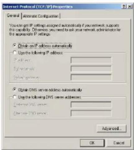
- Go to General tab, select Internet Protocol (TCP/IP) and click Properties.
- Go to General tab, select Obtain an IP address automatically and DNS server address automatically.
- Then, click OK.

Windows 95/98/Me
- Click Start → Settings → Control Panel. Double-click the Network icon.
-
Go to Configuration tab, select TCP/IP for network adapter installed and click Properties.
-
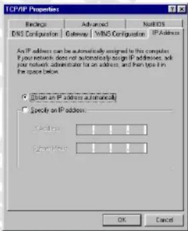
Go to IP Address tab and select Obtain an IP address automatically.
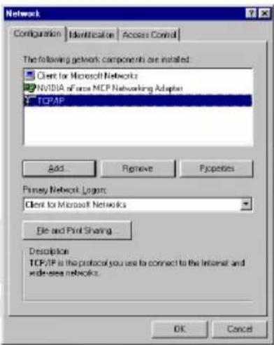
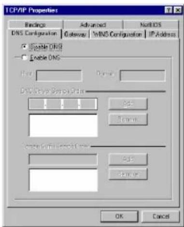
- Go to DNS Configuration tab, select Disable DNS and click OK.
Windows NT
- Click Start → Settings → Control Panel. Double-click the Network icon.
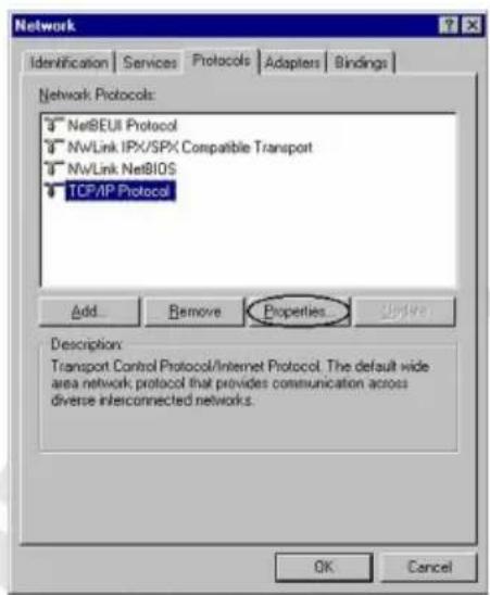
- Go to Protocols tab, select TCP/IP Protocol and click Properties.
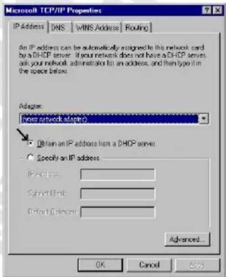
- Go to IP Address tab, select Obtain an IP address from DHCP server and click OK.
To make sure that network adapter properly obtained an IP address from router's DHCP server, click Start > Run and type cmd (Win 2000/XP) or command (Win 98/ME). In command line type ipconfig /all and check that value of the IP Address is 10.0.0.x
Configure router via web browser
Cerberus ADSL Wi-Fi Lite router can be configured via web browser, which is usually integrated with operating system. Router offers clear and simple interface.
Login
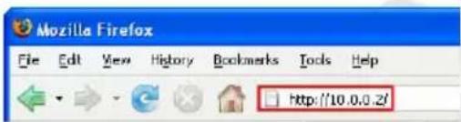
- Launch the Web browser
- Enter the default IP address: 10.0.0.2
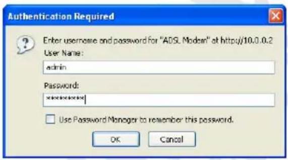
- Enter default username (admin) and password (trendchip)
Navigation
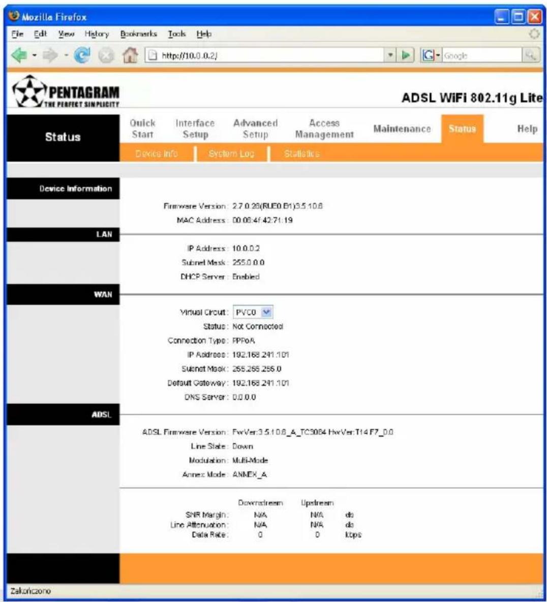
Steps to navigate the Web configuration from the Site Map are summarized below:
- Quick Start – wizard that helps to configure your router,
- Interface Setup – configure Internet and LAN functions,
- Advanced Setup – configure advanced features,
- Access Management – manage Internet access options,
- Maintenance – set a new password, set the time zone, upgrade or reload firmware and run diagnostic tests on the router,
- Status – router device information, system logs and performance statistics,
- Help – available help topics.
Quick Start Wizard
Click Quick Start to guide you to configure the device to connect your ISP and have Internet access within minutes. This Quick Start will guide you step by step to configure the password, time zone, and WAN settings of you device. This Wizard is a helpful guide for first time uses to the device. It is strongly recommended to use Quick Start to configure your ADSL settings.
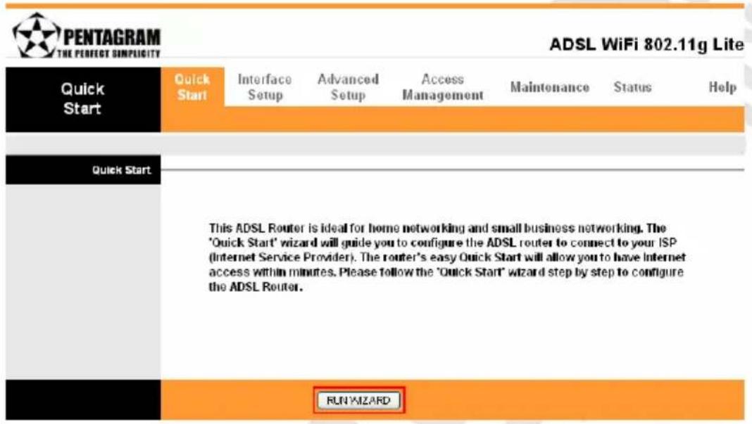
Click on the RUN WIZARD button to start the Quick Start wizard. The Quick Start wizard will open a new browser window with the following screen:
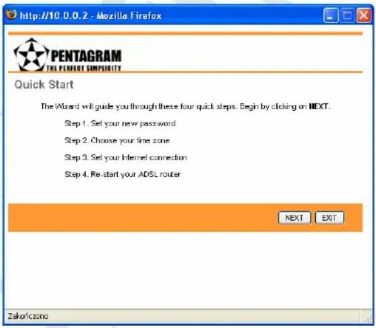
Please follow the quick start step by step to configure the device.
Click on NEXT to continue, or on EXIT to exit the wizard without saving.
Setting a New Password
This screen helps you set a new password, replacing the default password.
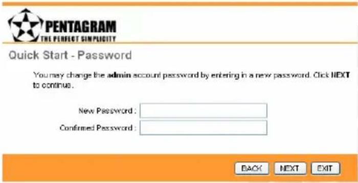
Enter new password in New Password and Confirmed Password fields.
Click on BACK to return to the previous screen, on NEXT to continue, or on EXIT to exit the wizard without saving.
Choose your Time Zone
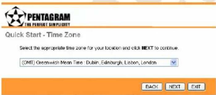
Select the appropriate time zone for your location from the dropdown list.
Click on BACK to return to the previous screen, on NEXT to continue, or on EXIT to exit the wizard without saving.
Set your Internet Connection
Glossary:
- Multiplexing - Two conventions identify what protocols a virtual circuit (VC) is carrying. Be sure to use the multiplexing method your ISP requires:
VC-Based Multiplexing – In VC-based multiplexing, by prior mutual agreement, each protocol is assigned to a specific virtual circuit. For example, VC1 carries IP, etc. VC-based multiplexing may be dominant in environments where dynamic creation of large numbers of ATM VCs is fast and economical.
LLC-Based Multiplexing – In LLC-based multiplexing, one VC carries multiple protocols with protocol-identifying information contained in each packet header. While this method requires extra bandwidth and processing overhead, this method may be advantageous if it is not practical to have a separate VC for each carried protocol; for example, if charging heavily depends on the number of simultaneous VCs.
- VPI and VCI - Be sure to use the Virtual Path Identifier (VPI) and Virtual Channel Identifier (VCI) numbers assigned to you. The valid range for the VPI is 0 to 255. The valid range for the VCI is 32 to 65535. 0 to 31 is reserved for local management of ATM traffic.
- PPPoA – Point-to-Point Protocol over ATM Adaptation Layer 5 (AAL5) (PPPoA) provides access control and billing functionality in a manner similar to dial-up services using PPP. The router encapsulates the PPP session based on RFC1483 and sends it through ATM PVC to the ISP's DSLAM.
- PPPoE – Point-to-Point Protocol over Ethernet provides access control and billing functionality in a manner similar to dial-up services using PPP. The router bridges a PPP session over Ethernet (PPP over Ethernet, RFC 2516) from your computer to an ATM Permanent Virtual Circuit (PVC) that connects to the ADSL Access Concentrator, where the PPP session terminates. Single PVC can support any number of PPP sessions from your LAN.

PENTAGRAM HE PERFECT SIMPLICITY
Quick Start - ISP Connection Type
Select the Internet connection type to connect to your ISP. Click NEXT to continue.
Dynamic IP Address
Choose this option to obtain a IP address automatically from your ISP.
Static P Address
Choose this option to set static IP information provided to you by your ISP.
PPPoE/PPPoA
Choose this option if your ISP uses PPPcE/PPPoA. (For most DSL users)
Bridge Mode
Choose this option if your ISP uses Bridge Mode.
BACK
NEXT
EXIT
Select the Internet connection type you use to connect to your ISP. The following screen will vary depending on which connection type you chose.
Click on BACK to return to the previous screen, on NEXT to continue, or on EXIT to exit the wizard.
• Dynamic IP Address
A dynamic IP address connection requests a new IP address from your ISP each time you connect to it.
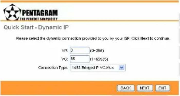
Enter VPI (Virtual Path Identifier), VCI (Virtual Channel Identifier) and select your Connection Type from the dropdown list. Your ISP should provide the above information.
Click on BACK to return to the previous screen, on NEXT to continue, or on EXIT to exit the wizard without saving.
- Static IP Address
A static IP address connection uses the same IP each time you connect to your ISP.
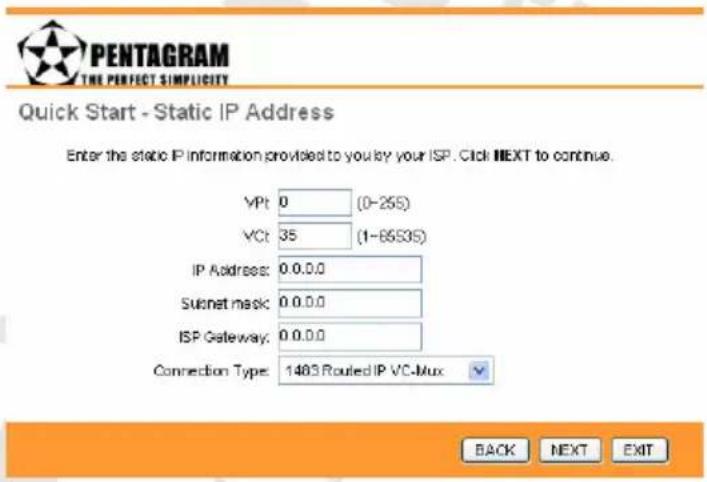
Enter VPI (Virtual Path Identifier), VCI (Virtual Channel Identifier), IP Address, Subnet mask, ISP Gateway and select your Connection Type from the dropdown list. Your ISP should provide the above information.
Click on BACK to return to the previous screen, on NEXT to continue, or on EXIT to exit the wizard without saving.
- PPPoE/PPPoA
Configure connection based on PPPoE / PPPoA protocol.
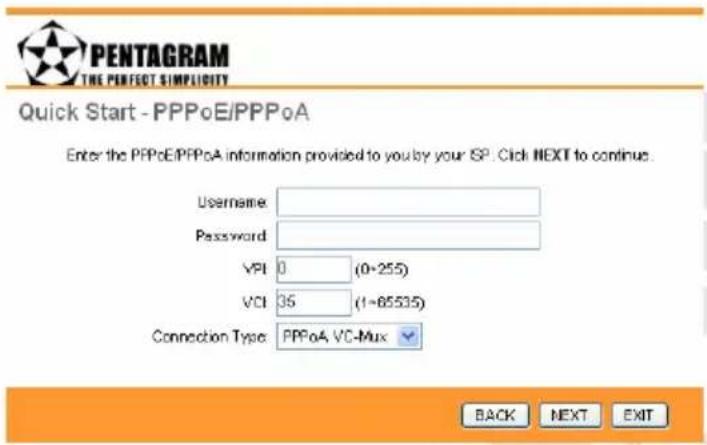
Enter Username, Password, VPI (Virtual Path Identifier), VCI (Virtual Channel Identifier) and select your Connection Type from the dropdown list. Note that you must enter the user name exactly as your ISP assigned it. If the assigned name is in the form of user@domain where domain identifies a service name, enter it exactly as given.
Click on BACK to return to the previous screen, on NEXT to continue, or on EXIT to exit the wizard without saving.
- Bridge Mode
RFC 1483 explains two methods for Multi-protocol Encapsulation over AAL5. The first method allows multiplexing of multiple protocols over just one ATM virtual circuit (LLC-based multiplexing). The second method assumes that each individual protocol is carried over a separate ATM virtual circuit (VC-based multiplexing). Please refer to RFC 1483 for more information.
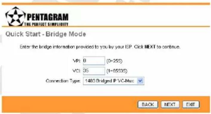
Enter VPI (Virtual Path Identifier), VCI (Virtual Channel Identifier) and select your Connection Type from the dropdown list. Your ISP should provide the above information.
Click on BACK to return to the previous screen, on NEXT to continue, or on EXIT to exit the wizard without saving.
Finishing the Wizard
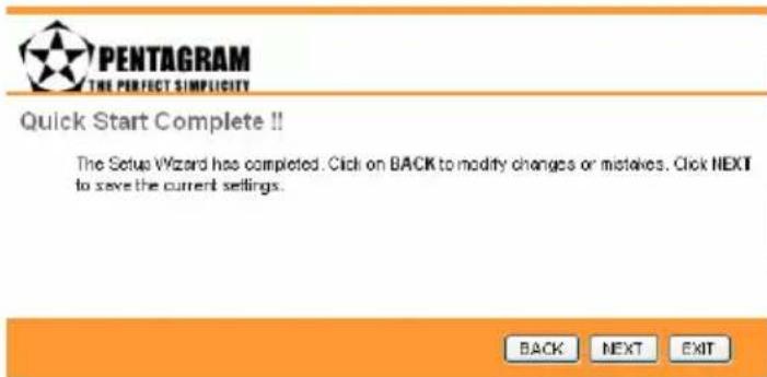
The Quick Start wizard now has all the information it needs.
Click on BACK to make changes or correct mistakes. Click on NEXT to save the current settings. Click on EXIT to exit the wizard without saving.
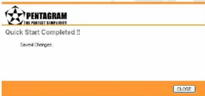
Your changes have been saved. Click on CLOSE. The Quick Start wizard window will close.
Interface Setup Tab
Glossary:
- RIP (Routing Information Protocol): Select this option to specify the RIP version, including RIP1, RIP2-B and RIP2-M. RIP2-B & RIP2-M are both sent in RIP-2 format, the difference is that RIP2-M using Multicast and RIP2-B using Broadcast format.
- RIP Direction: Select this option to specify the RIP direction. None is for disabling the RIP function. Both means the ADSL Router will periodically send routing information and accept routing information then incorporate into routing table. IN only means the ADSL router will only accept but will not send RIP packet. OUT only means the ADSL router will only sent but will not accept RIP packet.
- IGMP (Internet Group Multicast Protocol): It is a session-layer protocol used to establish membership in a multicast group. The ADSL supports both IGMP version IGMP-v1 & IGMP-v2. Select None to disable it.
Internet
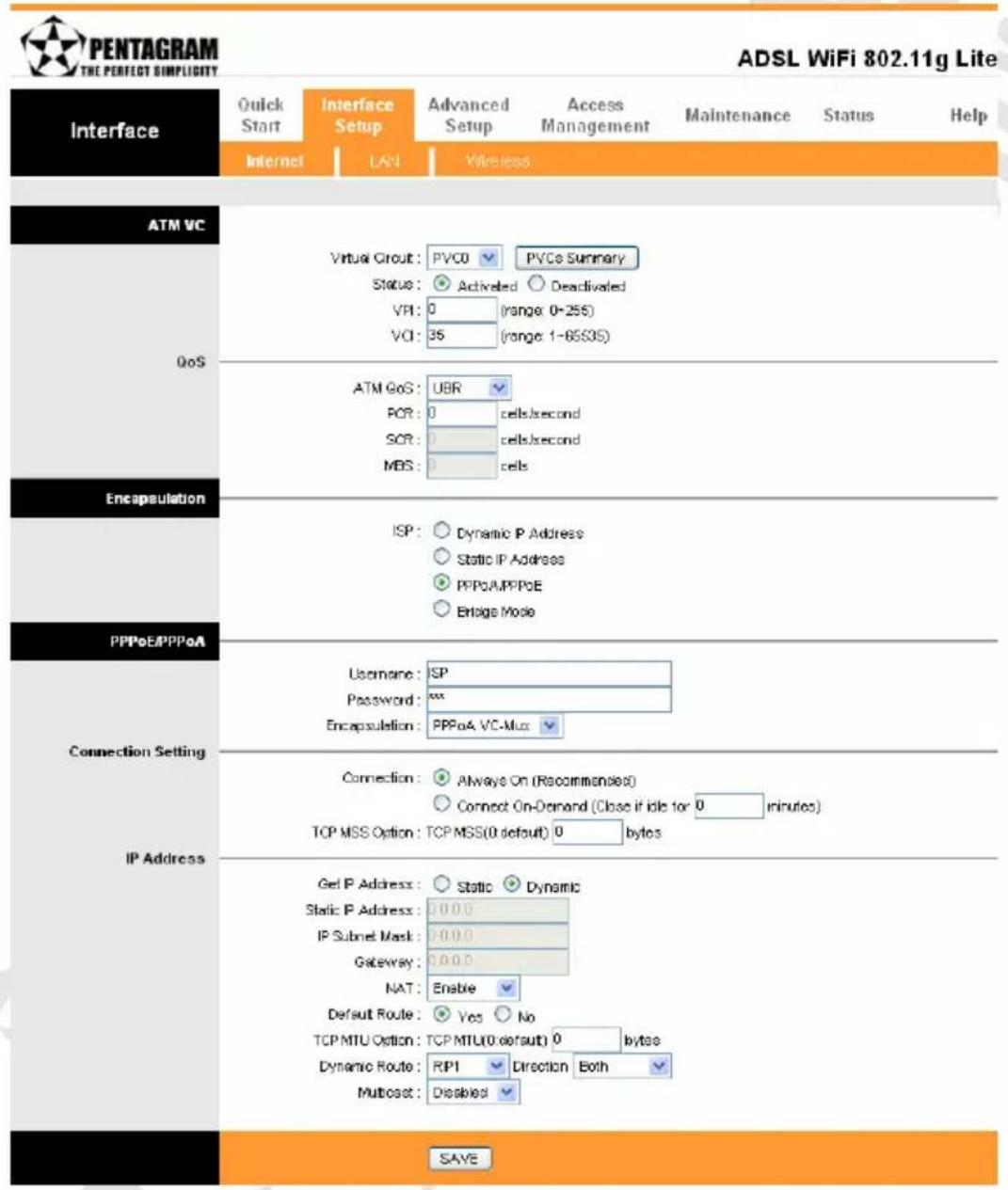
The Internet screen allows you to set up how your router connects to the Internet. If you already ran the Quick Start wizard, the information you provided to the wizard should be entered into the fields already. After you finish the changes, click on the SAVE button to save your changes.
• ATM VC
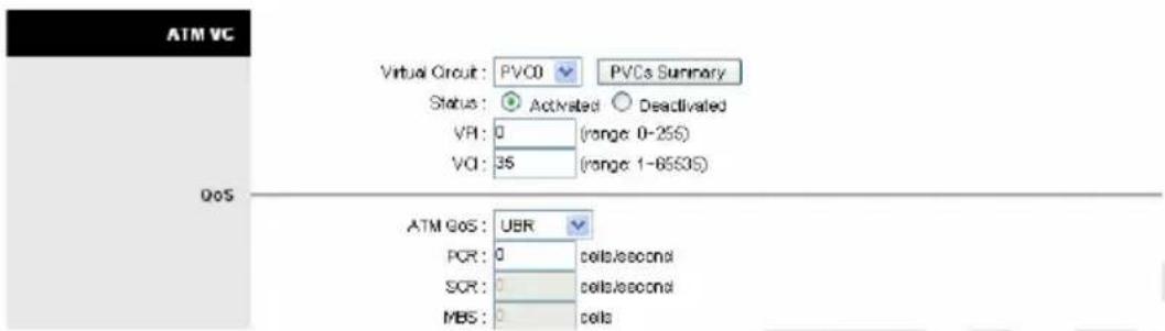
ATM settings are used to connect to your ISP. Your ISP provides VPI, VCI, settings to you. In this Device, you can totally setup 8 PVCs on different encapsulations if you apply 8 different virtual circuits from your ISP. You need to activate the VC to take effect. For PVCs management, you can use ATM QOS to setup each PVC traffic line's priority.
Virtual Circuit – Select the VC number you want to setup.
VPI – Virtual Path Identifier. The valid range for the VPI is 0 to 255.
VCI – Virtual Channel Identifier. The valid range for the VCI is 1 to 65635 (0 to 31 is reserved for local management of ATM traffic).
ATM QoS – Select the Quality of Service types for this Virtual Circuit. The ATM QoS types include CBR (Constant Bit Rate), VBR (Variable Bit Rate) and UBR (Unspecified Bit Rate). These QoS types are all controlled by the parameters specified below, including PCR, SCR, and MBS.
PCR (Peak Cell Rate) – Peak Cell Rate (PCR) is the maximum rate at which the sender can send cells. This parameter may be lower (but not higher) than the maximum line speed. 1 ATM cell is 53 bytes (424 bits), so a maximum speed of 832 Kbps gives a maximum PCR of 1962 cells/sec. This rate is not guaranteed because it is dependent on the line speed.
SCR (Sustained Cell Rate) – Sustained Cell Rate (SCR) is the mean cell rate of a burst, on-off traffic source that can be sent at the peak rate, and a parameter for burst-type traffic. SCR may not be greater than the PCR; the system default is 0 cells/sec.
MBS (Maximum Burst Size) – Maximum Burst Size (MBS) is the maximum number of cells that can be sent at the PCR. After MBS is reached, cell rates fall below SCR until cell rate averages to the SCR again. At this time, more cells (up to the MBS) can be sent at the PCR again.
CBR (Constant Bit Rate) – is for connections that support constant rates of data transfer. The only parameter you need to worry about in CBR is PCR.
UBR (Unspecified Data Rate) – is for connections that have variable traffic. The only parameter you need to worry about in UBR is PCR.
rtVBR (real time Variable Bit Rate) – is for connections that, while having variable traffic, require precise timing between traffic source and destination. PCR, SCR and MBS must all be set for rtVBR.
nrtVBR (non real time Variable Bit Rate) – is for connections that have variable traffic, do not require precise timing, but still require a set bandwidth availability. PCR, SCR and MBS must all be set for nrtVBR.
- Encapsulation
Select the encapsulation protocol your ISP uses. The following section will vary depending on which encapsulation protocol you select.

• Dynamic IP Address
Select this option if your ISP provides you an IP address automatically. Please enter the Dynamic IP information accordingly.
Dynamic IP
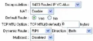
Encapsulation – Select your encapsulation type from the dropdown list.
NAT – Select whether NAT (Network Address Translation) is Enabled or Disabled.
Default Route – Select whether this PVC will be the default route for Internet data.
TCP MTU Option – Enter TCP MTU (Maximum Transmission Unit) Value here.
Dynamic Route – Select the RIP type and direction from the dropdown lists.
Multicast – Select the multicast protocol you wish to use from the dropdown list.
- Static IP Address
Select this option to set static IP information.
Static IP
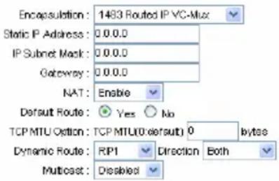
Encapsulation – Select your encapsulation type from the dropdown list.
Static IP Address – Enter the static IP Address here.
IP Subnet Mask – Enter the IP Subnet Mask here.
Gateway – Enter the Gateway address here.
NAT – Select whether NAT (Network Address Translation) is Enabled or Disabled.
Default Route – Select whether this PVC will be the default route for Internet data.
TCP MTU Option – Enter TCP MTU (Maximum Transmission Unit) Value here.
Dynamic Route – Select the RIP type and direction from the dropdown lists.
Multicast – Select the multicast protocol you wish to use from the dropdown list.
- PPPoA/PPPoE
Select this option if your ISP requires you to use a PPPoA/PPPoE connection.
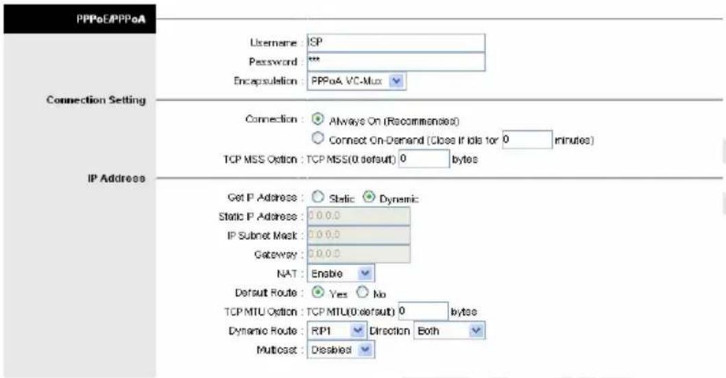
Username – Enter your username for your PPPoE/PPPoA connection.
Password – Enter your password for your PPPoE/PPPoA connection.
Encapsulation – Select your encapsulation type from the dropdown list.
Connection – Select whether your connection is always on or if it connects on demand. If on demand, specify how many minutes the connection may be idle before it disconnects.
TCP MMS Option – Enter the TCP MSS (Maximum Segment Size) you wish to use here.
Get IP Address – Choose whether the router obtains the IP address statically or dynamically.
Static IP Address – Enter the static IP address here. Only if you chose Static above.
IP Subnet Mask – Enter the IP subnet mask here. Only if you chose Static above.
Gateway – Enter the gateway here. Only if you chose Static above.
NAT – Select whether NAT (Network Address Translation) is Enabled or Disabled.
Default Route – Select whether this PVC will be the default route for Internet data.
TCP MTU Option – Enter TCP MTU (Maximum Transmission Unit) Value here.
Dynamic Route – Select the RIP type and direction from the dropdown lists.
Multicast – Select the multicast protocol you wish to use from the dropdown list.
- Bridge Mode
The modem can be configured to act as a bridging device between your LAN and your ISP. Bridges are devices that enable 2 or more networks to communicate as if they are 2 segments of the same physical LAN. Please set the Connection type.

Encapsulation – Select your encapsulation type from the dropdown list.
LAN
There are the IP settings of the LAN Interface for the device. These settings may be referred to as Private settings. You may change the LAN IP address if needed. The LAN IP address is provided to your internal network and cannot be seen on the Internet.
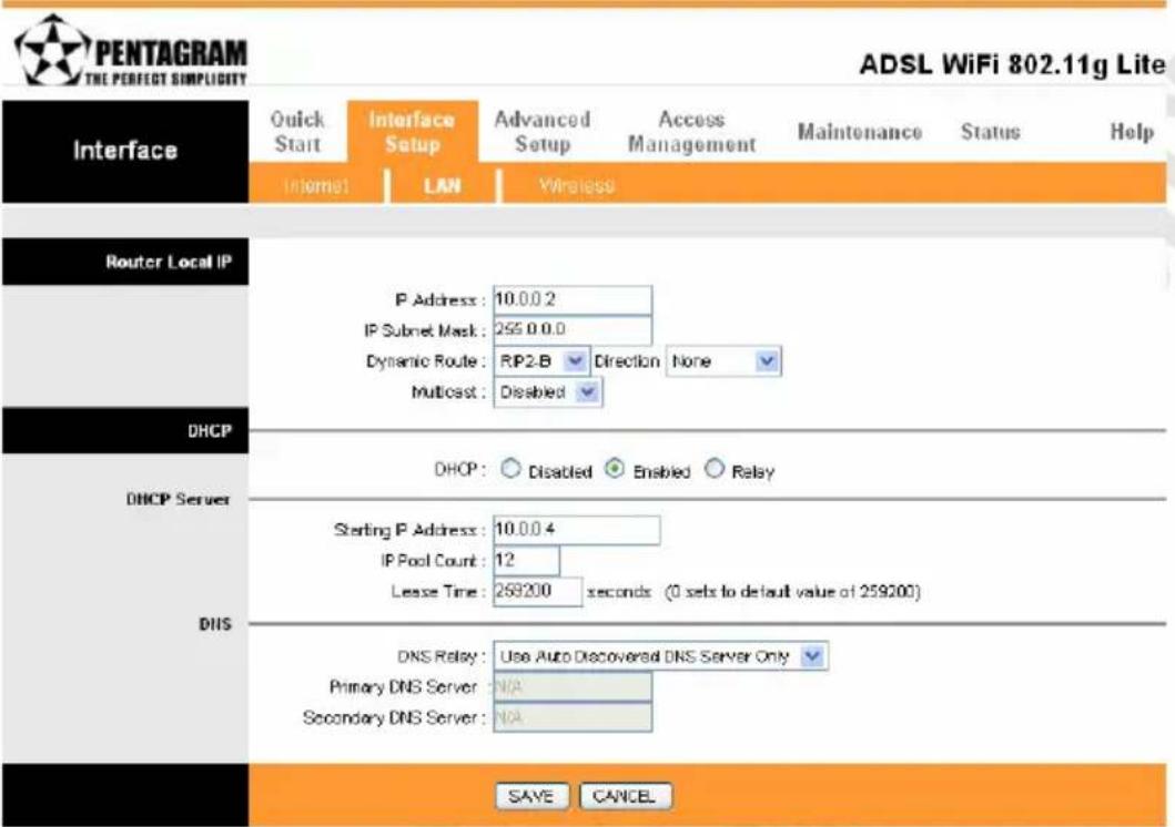
- Router Local IP
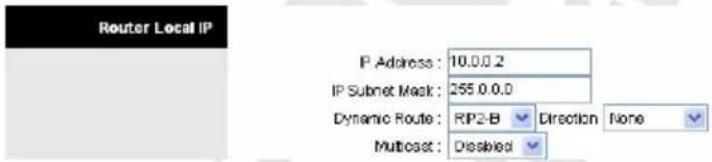
IP Address – Enter the IP address of your ADSL router in dotted decimal notation, for example, 10.0.0.2 (default setting).
IP Subnet Mask – Your ADSL router will automatically calculate the subnet mask based on the IP address that you assign. Unless you are implementing sub netting, use the subnet mask computed by the ADSL router.
Dynamic Route – Select the Dynamic Route from RIP1, RIP2-B, and RIP2-M. Please refer to Internet → Dynamic Route. The only difference is the interface.
Multicast – IGMP (Internet Group Multicast Protocol) is a session-layer protocol used to establish membership in a multicast group. Please refer to Internet → Multicast. The only difference is the interface.
• DHCP
The DHCP Server gives out IP addresses when a device is booting up and request an IP to be logged on to the network. It must be set as a DHCP client to obtain the IP address automatically. By default, the DHCP Server is enabled. The DHCP address pool contains the range of the IP address that will automatically be assigned to the client on the network.
Disabled – DHCP server is Disabled
Enabled – DHCP server is Enabled
Relay - router acts as a relay to different computer/device.
Disabled

Enabled
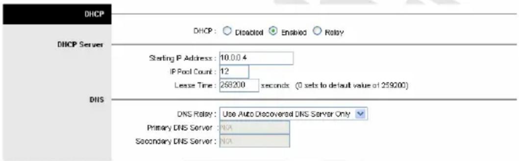
Starting IP Address – Enter the starting IP address you wish to use as the DHCP server's IP assignment.
IP Pool Count – Enter the maximum user pool size you wish to allow.
Lease Time – Enter the amount of time you wish to lease out a given IP address.
DNS Relay – Select the DNS relay option you wish to use from the dropdown list.
Primary DNS – Enter the primary DNS server IP address you wish to use. For user discovered DNS only.
Secondary DNS – Enter the secondary DNS server IP address you wish to use. For user discovered DNS only.
Relay
A DHCP relay is a computer that forwards DHCP data between computers that request IP addresses and the DHCP server that assigns the addresses. Each of the device's interfaces can be configured as a DHCP relay. If it is enable, the DHCP requests from local PCs will forward to the DHCP server runs on WAN side. To have this function working properly, please run on router mode only, disable the DHCP server on the LAN port, and make sure the routing table has the correct routing entry.

DHCP Server IP for Relay Agent – The DHCP server IP Address runs on WAN side.
Wireless
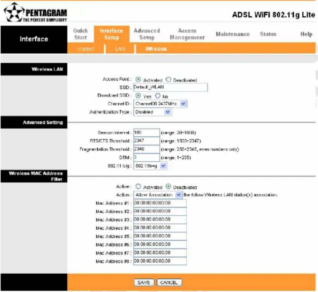
- Wireless LAN
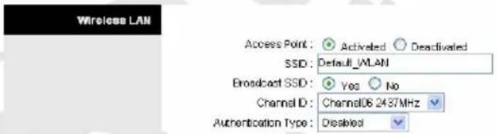
Access Point – Activate or deactivate Access Point function of router.
SSID –The SSID is a unique name to identify the ADSL Router in the Wireless LAN. Wireless Clients associating to the ADSL Router must have the same SSID.
Broadcast SSID – Select No to hide the SSID such that a station can not obtain the SSID through passive scanning. Select Yes to make the SSID visible so a station can obtain in the SSID through Passive scanning.
Channel ID – The range of radio frequencies used by IEEE 802.11b/g wireless devices us called a channel.
Authentication Type – Appearance of next paragraph depends on this option.
• WEP
Wired Equivalent Privacy encrypts data frames before transmitting over the wireless network. Select Disable to allow all wireless computers to communicate with the access points without any data encryption. Select 64-bit WEP or 128-bit WEP to use data encryption.

Key #1-4 – The WEP keys are used to encrypt data. Both the ADSL Router and the wireless clients must use the same WEP key for data transmission. Enter any 10 (WEP 64bit) or 26 (WEP 128bit) hexadecimal digits ("0-9", "A-F") preceded by 0x for each key (1-4). The values must be set up exactly the same on the Access Points as they are on the wireless client stations.
- WPA-PSK
WPA-PSK (Wi-Fi Protected Access, Pre-Shared Key) Encrypts data frames before transmitting over the wireless network.

Encryption – Encryption method – TKIP for WPA-PSK, AES for WPA-PSK
Pre-Shared Key – Key used to encrypt data. Both the ADSL Router and the wireless clients must use the same WPA-PSK Key for data transmission.
- Advanced Setting

Beacon Interval – The Beacon Interval value indicates the frequency interval of the beacon. Enter a value between 20 and 1000. A beacon is a packet broadcast by the Router to synchronize the wireless network.
RTS/CTS – The RTS (Request To Send) threshold (number of bytes) for enabling RTS/CTS handshake. Data with its frame size larger than this value will perform the RTS/CTS handshake. Set this attribute to be larger than the maximum MSDU (MAC Service Data Unit) size TURNS OFF the RTS/CTS handshake. Set this attribute to ZERO TURNS ON the RTS/CTS handshake. Enter a value between 0 and 2432.
Fragmentation Threshold - The threshold (number of bytes) for the fragmentation boundary for directed messages. It is the maximum data fragment size that can be sent.
Enter a value between 256 and 2432.
DTIM – This value is between 1 and 255, indicates the interval of the Delivery Traffic Indication Message (DTIM).
802.11 b/g - Wireless standard used in this wireless network.
- Wireless MAC Address Filter
You can allow or deny a lust of MAC addresses associated with the wireless stations access to the ADSL Router.
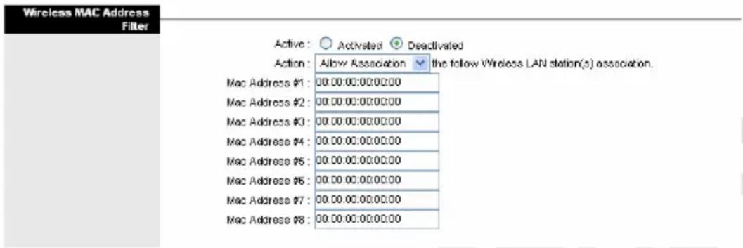
Active – Use this option to enable or disable MAC address filtering.
Action – Select Deny Association to block access to the router, MAC addresses not listed will be allowed to access the router. Select Allow Association to permit access to the router, MAC addresses not listed will be denied access to the router.
Mac Address #1-8 – list of MAC addresses allowed or not to use this network.
Advanced Setup Tab
Firewall
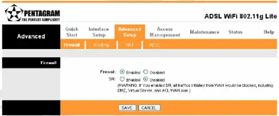
Firewall – Select this option can automatically detect and block Denial of Service (DoS) attacks, such as Ping of Death, SYN Flood, Port Scan and Land Attack.
SPI – Select this option to Enable or Disable the SPI feature. (NOTE: If you enable SPI, all traffics initiate from WAN would be blocked, including DMZ, Virtual Server, and ACL WAN side).
Routing
This table lists IP address of Internet destinations commonly accessed by your network. When a computer requests to send data to a listed destination, the device uses the Gateway IP to identify the first Internet router it should contact to route the data most efficiently. Select this option will list the routing table information. You can press ADD ROUTE to edit the static route. (As below screen)
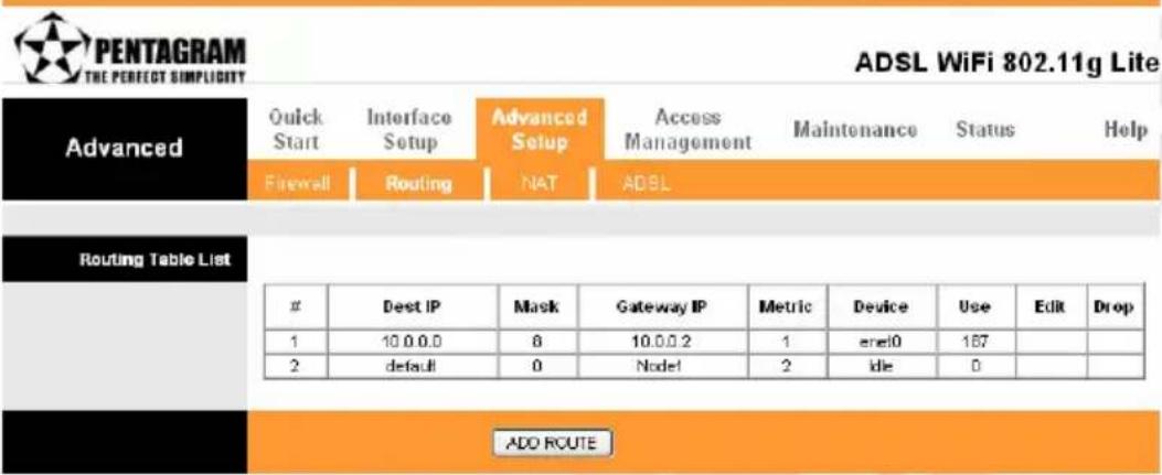
ADD ROUTE – click this button to set Static Routing information.
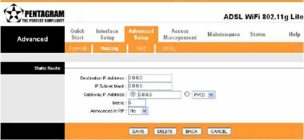
Destination IP Address – This parameter specifies the IP network address of the final destination of packets routed by this rule.
IP Subnet Mask – Enter the subnet mask for this destination.
Gateway IP Address – Enter the IP address of the gateway. A gateway does the actual forwarding of the packets. Enter the gateway's IP address in the field or select which PVC you wish to act as a gateway. The gateway is an immediate neighbor of your ADSL Router that will forward the packet to the destination. On the LAN, the gateway must be a router on the same segment as your Router; over Internet (WAN), the gateway must be the IP address of one of the remote nodes.
Metric – Metric represents the “cost” of transmission for routing purposes. IP Routing uses hop count as the measurement of cost, with a minimum of 1 for directly connected networks. Enter a number that approximates the cost for this link. The number need not to be precise, but it must between 1 and 15. In practice, 2 or 3 is usually a good number.
Announced in RIP – This parameter determines if the ADSL router includes the router to this remote node in its RIP broadcasts. If you choose Yes, the router in this remote node will be
propagated to other hosts through RIP broadcasts. If you choose No, this route is kept private and is not included in the RIP broadcasts.
When you are done making changes, click on SAVE to save your changes, DELETE to delete the rule with the parameters you set, BACK to return to the previous screen or CANCEL to exit without saving.
NAT
What NAT Does
NAT changes the source IP address in a packet received from a subscriber (the inside local address) to another (the inside global address) before forwarding the packet to the WAN side. When the response comes back, NAT translates the destination address (the inside global address) back to the inside local address before forwarding it to the original inside host. Note that the IP address (either local or global) of an outside host is never changed. The global IP addresses for the inside hosts can be either static or dynamically assigned by the ISP. You may also designate servers, such as a Web server and a telnet server, on your local network and make them accessible to the outside world. With no servers defined, your router filters out all incoming inquiries, thus preventing intruders from probing your network. For more information on IP address translation, refer to RFC 1631, The IP Network Address Translator (NAT).
Inside/outside indicates where a host is located relative to the router. The computers hosts of your LAN are inside, while the Web servers on the Internet are outside. Global/local indicates the IP address of a host in a packet as the packet traverses a router. The local address refers to the IP address of a host when the packet is in the local network, while the global address refers to the IP address of the host when the same packet is traveling in the WAN side.
Note that inside/outside refers to the location of a host, while global/local refers to the IP address of a host used in a packet. Thus, an inside local address (ILA) is the IP address of an inside host of a packet when the packet is still in the local network, while an inside global address (IGA) is the IP address of the same inside host when the packet is on the WAN side. The following table summarizes this information.
How NAT Works
Each packet has two addresses – a source address and a destination address. For outgoing packets, the ILA is the source address on the LAN, and the IGA is the source address on the WAN. For incoming packets, the ILA is the destination address on the LAN, and the IGA is the destination address on the WAN. NAT maps private (local) IP addresses to globally unique ones required for communication with hosts on other networks. It replaces the original IP source address (and TCP or UDP source port numbers for Many-to-One and Many-to-Many Overload NAT mapping) in each packet and then forwards it to the Internet. The ROUTER keeps track of the original addresses and port numbers so incoming reply packets can have their original values restored.
NAT Mapping Types
NAT supports five types of IP/port mapping. They are:
One-to-One – In One-to-One mode, the TC3162 EVM maps one local IP address to one global IP address.
Many-to-One – In Many-to-One mode, the TC3162 EVM maps multiple local IP addresses to one global IP address.
Many-to-Many Overload – In Many-to-Many Overload mode, the TC3162 EVM maps multiple local IP addresses to shared global IP addresses.
Many-to-Many No Overload – In Many-to-Many No Overload mode, the TC3162 EVM maps each local IP address to a unique global IP address.
Cerberus ADSL Wi-Fi Lite
Server – This type allows you to specify inside servers of different services behind the NAT to be accessible to the outside world. The following table summarizes these types.
| TYPE IP MAPPING | |
| One-to-One ILA1 IGA1 | |
| Many-to-One (SUA/PAT) ILA1 IGA1 | ILA2 IGA1... |
| Many-to-Many Overload ILA1 IGA1 | ILA2 IGA2ILA3 IGA1ILA4 IGA2... |
| Many-to-Many No Overload ILA1 | IGA1ILA2 IGA2ILA3 IGA3ILA4 IGA4... |
| Server Server IP 1 IGA1 | Server IP 2 IGA1Server IP 3 IGA1 |
NAT (Network Address Translation) is a method for disguising the private IP addresses you use on your LAN as the public IP address you use on the Internet. You define NAT rules that specify exactly how and when to translate between public and private IP addresses. Simply select this option to setup the NAT function for your ADSL router.
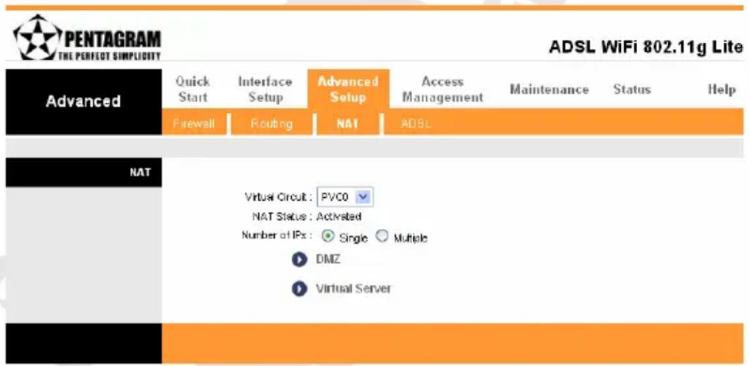
Virtual Circuit – The Virtual Circuit (VC) properties of the ATM VC interface identify a unique path that your ADSL/Ethernet router uses to communicate via the ATM-based network with the telephone company central office equipment.
Nat Status – This filed shows the current status of the NAT function for the current VC.
Number of IPs – This field is to specify how many IPs are provided by your ISP for current VC. It can be single IP or multiple IPs. Note: For VCs with single IP, they share the same DMZ & Virtual servers; for VCs with multiple IPs, each VC cab set DMZ and Virtual servers. Furthermore, for VCs with multiple IPs, they can define the Address Mapping rules; for VCs with single IP, since they have only one IP, there is no need to individually define the Address Mapping rule.
DMZ / Virtual Server / IP Address Mapping – opens corresponding page:
• DMZ
A DMZ (de-militarized zone) is a host between a private local network and the outside public network. It prevents outside users from getting direct access to a server that has company data. Users of the public network outside the company can access only the DMZ host.
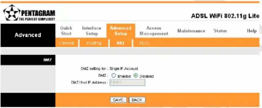
DMZ setting for – Option selected in Number of IPs field in main NAT window.
DMZ – Toggle the DMZ function Enabled or Disabled.
DMZ Host IP Address – Enter the specified IP Address for DMZ host on the LAN side
When you are done making changes, click on SAVE to save your changes or on BACK to return to the previous screen.
- Virtual Server
The Virtual Server is the server or server(s) behind NAT (on the LAN), for example, Web server or FTP server, that you can make visible to the outside world even though NAT makes your whole inside network appear as a single machine to the outside world.
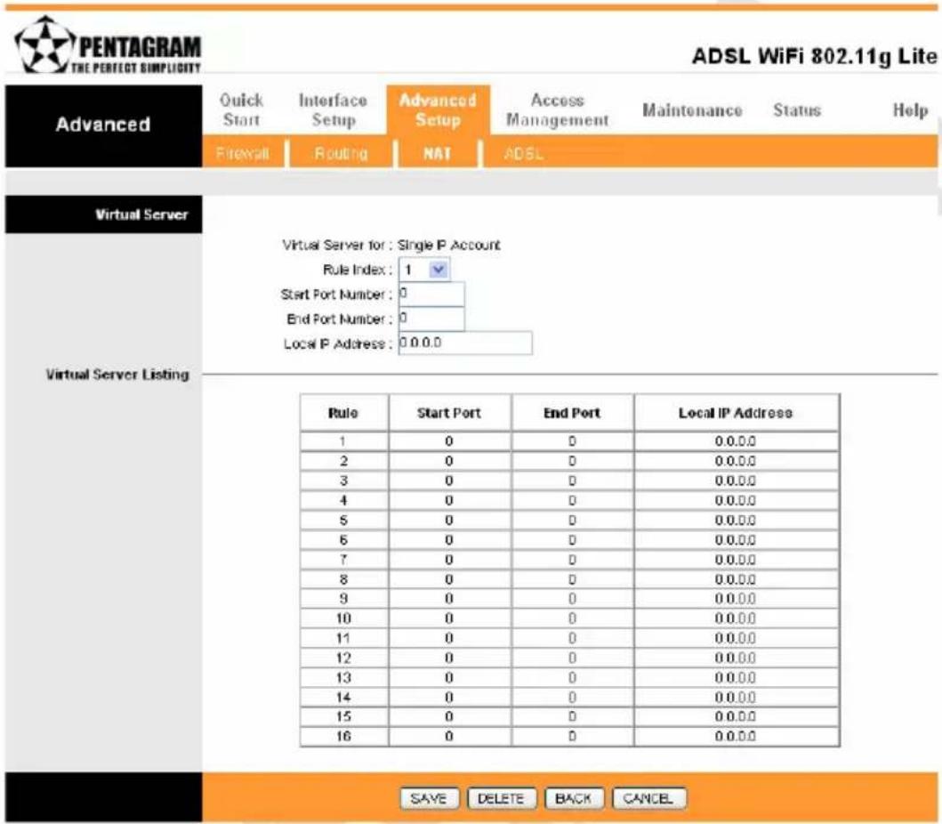
Virtual Server for - selected in Number of IPs field in main NAT window.
Rule Index – The Virtual server rule index for this VC. You can specify up to 10 rules. All the VCs with single IP will use the same Virtual Server rules.
Start Port Number / End Port Number – Enter the specific Start and End Port number you want to forward. If
it is one port only, you can enter the End port number the same as Start port number. For example, set the FTP Virtual server, you can set the start and end port number to 21.
Local IP Address – Enter the IP Address for the Virtual Server in LAN side.
Virtual Server Listing – This is a listing of all virtual servers your have set.
When you are done making changes, click on SAVE to save your changes, DELETE to delete the rule with the parameters you set, BACK to return to the previous screen or CANCEL to exit without saving.
- IP Address Mapping
The IP Address Mapping is for those VCs that with multiple IPs. The IP Address Mapping rule is per-VC based. (only for Multiple IPs' VCs).

ADSL WiFi 802.11g Lite
Advanced
Quick
Start
Interface
Setup
Advanced
Setup
m = 311
Management
Maintenance
Status
Help
Firewall
Routing
NAT
ADSL
IP Address Mapping
Address Mapping List
Address Mapping Rule : PVCD
Rule Index:
Rule Type
Local Start P:
Local End P
Public Start P:
Public End P

(0.0.0.0 for modern's WAN P)
| Rule | Type | Local Start IP | Local End IP | Public Start IP | Public End IP |
| 1 | - | 0.0.0.0 | ... | 0.0.0.0 | ... |
| 2 | - | 0.0.0.0 | ... | 0.0.0.0 | ... |
| 3 | - | 0.0.0.0 | ... | 0.0.0.0 | ... |
| 4 | - | 0.0.0.0 | ... | 0.0.0.0 | ... |
| 5 | - | 0.0.0.0 | ... | 0.0.0.0 | ... |
| 6 | - | 0.0.0.0 | ... | 0.0.0.0 | ... |
| 7 | - | 0.0.0.0 | ... | 0.0.0.0 | ... |
| 8 | - | 0.0.0.0 | ... | 0.0.0.0 | ... |
SAVE
DELETE
BACK
CANCEL
Address Mapping Rule – PVC to set.
Rule Index – The Virtual server rule index for this VC. You can specify up to 16 rules. All the VCs with single IP will use the same Virtual Server rules.
Rule Type – There are 4 types of One-to-One, Many-to-One, Many-to-Many Overload and Many-to-Many No-Overload.
Local Start IP / Local End IP – Enter the local IP address you plan to map to. Local Start IP is the starting local IP address & Local End IP is the ending local IP address. If the rule is for all local IPs, then the Start IP is 0.0.0.0 and the End IP is 255.255.255.255.
Public Start IP / Public End IP – Enter the Public IP Address you want to do NAT. Public Start IP is the starting Public IP Address and Public End IP is the ending Public IP Address. If you have a Dynamic IP, enter 0.0.0.0 as the Public Start IP.
When you are done making changes, click on SAVE to save your changes, DELETE to delete the rule with the parameters you set, BACK to return to the previous screen or CANCEL to exit without saving.
ADSL
Select this option to set ADSL Mode and ADSL Type information.
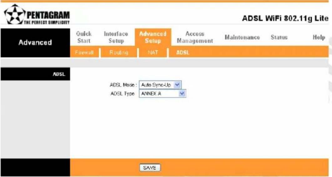
ADSL Mode – Select which mode your ADSL connection uses from the dropdown list. The option has Auto Sync-up, ADSL2+, ADSL2, G.DMT, T1.413, G.LITE.
ADSL Type – Select the ADSL type you use from the dropdown list: ANNEX A, ANNEX I, ANNEX A/L, ANNEX M, ANNEX A/I/J/L/M.
When you are done making changes, click on SAVE to save your changes.
Access Management Tab
ACL
Go to Access Management → ACL to enable remote management. Access Control Listing (ACL) is a management tool that acts as a filter for incoming or outgoing packets, based on application. You may use telnet or Web to remotely manage the ADSL Router. User just needs to enable Telnet or Web and give it an IP address that wants to access the ADSL Router. The default IP 0.0.0.0 allows any client to use this service to remotely manage the ADSL Router.
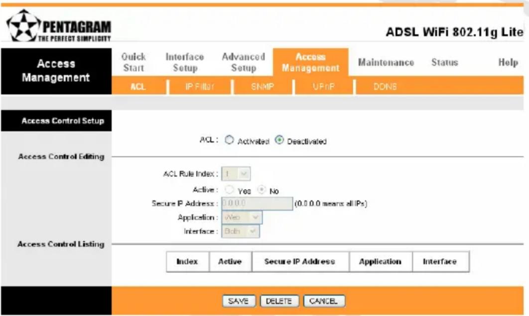
ACL – There has Activated & Deactivated option. The default setting is Deactivated which means all IP can access via router. If you choose Activated, you only can access via router by listed IP addresses.
ACL Rule Index – Index number from 1 and up to 16.
Active – Once you choose Yes then you can access the IP via router.
Application – Each of these labels denotes a service that you may use to remotely manage the Router. Choices are Web, FTP, Telnet, SNMP, Ping, ALL.
Interface – Select the access interface. Choices are WAN, LAN and Both.
UWAGA!
- You must set one ACL index to access your router via LAN interface. If you don't, your router cannot access other listed IP Address. (Refer to Index 1).
- Remember! Once you active your ACL function, you only can access via router by listed Secure IP Address.
When you are done making changes, click on SAVE to save your changes, DELETE to delete the rule with the parameters you set or CANCEL to exit without saving.
IP Filter
The Router provides extensive firewall protection by restricting connection parameters to limit the risk of intrusion and defending against a wide array of common hacker attackers. Go to Access Management → IP Filtering to set different IP filter rules of a given protocol (TCP, UDP, or ICMP) and a specific direction (incoming, outgoing, or both) to filter the packets. IP Filter is a more complex filtering tool, based more on IP and custom rules. Each of the indices can hold six rules, and each interface can have four associated indices, allowing 24 rules per interface. If all six rules in an index are Next rules, the data will be sent to the next index for filtering.
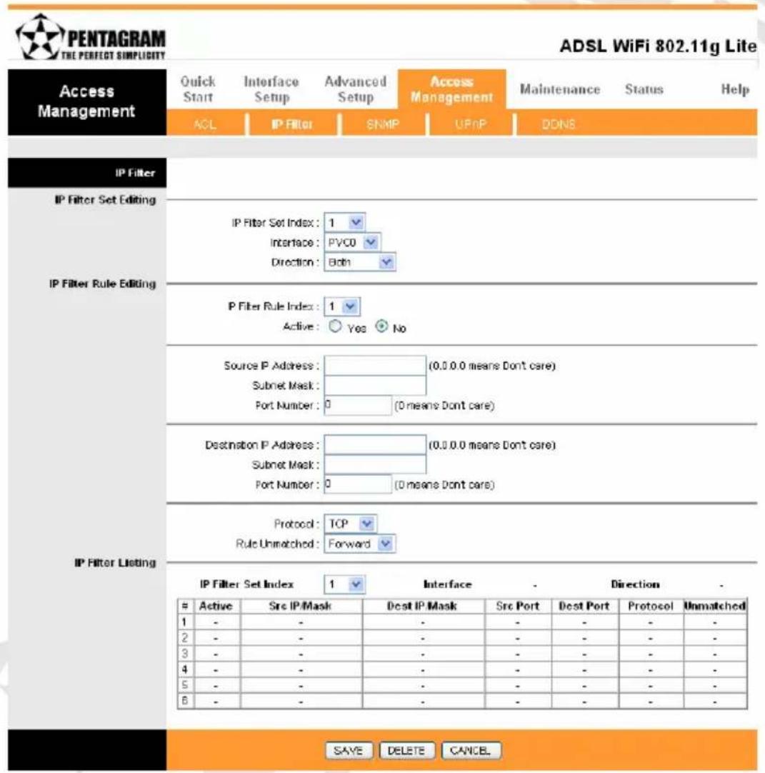
IP Filter Set Index – The IP Filter Set Index from 1 to 12 and each index can set up to 6 IP Filter.
Interface – Choices from PVC0 to PVC7 and LAN.
Direction – Choices are Both, Incoming and Outgoing. Select which direction of data flow you wish to apply the filters to. Note that Incoming and Outgoing are from the point of view of your router, relative to the interface you select. For WAN, data coming from outside your system is considered Incoming and data leaving your system is Outgoing. For LAN, data leaving your system is considered Incoming and data entering your system is Outgoing.
IP Filter Rule Index – Select the IP Filter Rule Index you wish to modify.
Active - Toggle this rule index on or off with Yes or No, respectively.
Source IP Address – Enter the source IP address you wish to deny access to your system.
Subnet Mask – Enter the subnet mask of the source IP address.
Port Number – Enter the port number of the source IP address. Note that 0 means all that ports are allowed.
Destination IP Address – Enter the destination IP address that you wish to deny access to your system.
Subnet Mask – Enter the subnet mask of the destination IP address.
Port Number – Enter the port number of the destination IP address. Note that 0 means that all ports are allowed.
Protocol – Select the protocol to filter. Choices are TCP, UDP, and ICMP.
Rule Unmatched – Choices are Forward and Next. Select what happens to the data in question if the rule you are currently editing is unmatched. Next means that the data is then compared to the next IP filter rule. Forward means that the data will be allowed into your system. Note that a Forward rule should be the last rule, as no data will be compared to rules after a Forward rule.
IP Filter Set Index – Select the IP filter set you wish to view.
Please follow below steps to set your IP Filter:
-
IP Filter Set Editing: Choose your IP Filter Set Index, Interface and Direction options. Remember, Interface and Direction functions are affected with IP Filter Set Index. EX: if your 1^st index set of IP filter set PVC0 as Interface and Outgoing as Direction, so the list of 1^st IP Filter will be PVC0 and Outgoing as their settings
-
IP Filter Rule Editing: Select the IP Filter Rule Index (up to 6 numbers for each set index) and choose Active option. As an example, Source IP Address is 10.0.0.10, Subnet Mask is 255.255.255.255, Destination IP Address & Subnet Mask is 0.0.0.0, Port Number is 80. And, Protocol sets TCP. From this setting, it filters 192.168.1.14, so it cannot access the web. Notice, each IP Filter Set Index can has up to 6 filters IP. At "Rule Unmatched" option, you must choose NEXT until the last filter IP choose Forward.
-
After every setting is done, click SAVE to continue next IP Filter Editing.
SNMP
The Simple Network Management Protocol (SNMP) is used for exchanging information between network devices. It enables a host computer to access configuration, performance, and other system data that resides in a database on the modem. The host computer is called a management station and the modem is called an SNMP agent. The data that can be accessed via SNMP is stored in a Management Information Database (MIB) on the modem.
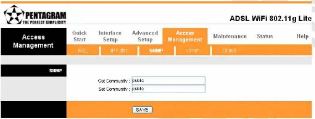
Get Community – Select to set the password for incoming Get- and GetNext request from management station.
Set Community – Select to set the password for incoming Set request from management station. The default password is 'public'.
When you are done making changes, click on SAVE to save your changes.
UPnP
UPnP (Universal Plug and Play) is a distributed, open networking standard that uses TCP/IP for simple peer-to-peer network connectivity between devices. An UPnP device can dynamically join a network, obtain an IP address, convey its capabilities and learn about other devices on the network. In turn, a device can leave a network smoothly an automatically when it is no longer in use. UPnP broadcasts are only allowed on the LAN.
UPnP hardware is identified as an icon in the Network Connections folder (in Windows XP & Windows ME). Each UPnP-compatible device that is installed on your network will appear as a separate icon.
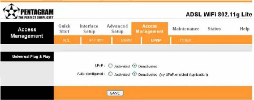
UPnP – You can choose "Activated" or "Deactivated" option from this session.
Auto-Configured – UPnP network devices can automatically configure network addressing, announce their presence in the network to other UPnP devices and enable exchange of simple product and service descriptions. Choose “Activated” option to allow UPnP-enabled applications to automatically configure the ADSL Router so that they can communicate through the ADSL Router, for example by using NAT traversal, UPnP applications automatically reserve a NAT forwarding port in order to communicate with another UPnP enabled device; this eliminates the need to manually configure port forwarding for the UPP enabled application. If you don’t want to make configuration changes through UPnP, just choose “Deactivated”.
Click SAVE to save the setting to the ADSL Router.
DDNS
The Dynamic Domain Name System allows you to update your current dynamic IP address with one or many dynamic DNS services so that anyone can contact you (in NetMeeting, CU-SeeMe, etc.). You can also access your FTP server or Web site on your own computer using a DNS-like address (for instance myhost.dhs.org, where my host is a name of your choice) that will never change instead of using an IP address that changes each time you reconnect. Your friends or relatives will always be able to call you even if they don't know your IP address. First of all, you need to have registered a dynamic DNS account with www.dyndns.org. This is for people with a dynamic IP from their ISP or DHCP server that would still like to have a DNS name. The Dynamic DNS service provider will give you a password or key.
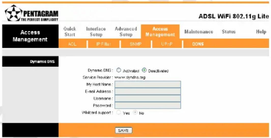
Dynamic DNS – Choose the option for Activated or Deactivated DDNS.
Service Provider – The default Dynamic DNS service provider is www.dyndns.org.
My Host Name – Type the domain name assigned to your ADSL by your Dynamic DNS provider.
E-mail Address – Type your e-mail address.
Username – Type your user name.
Password – Type the password assigned to you.
Wildcard support – Select Yes or No to turn on DYNDNS Wildcard. Enabling the wildcard feature for your host causes *.yourhost.dyndns.org to be aliased to the same IP address as yourhost.dyndns.org. This feature is useful if you want to be able to use, for example, www.yourhost.dyndns.org and still reach your hostname.
Click SAVE to save your changes.
Maintenance Tab
Administration
There is only one account that can access Web-Management interface-Administration. Admin has read/write access privilege. In this web page, you can set new password for admin.
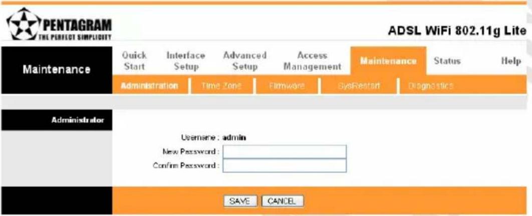
New Password – Type the new password in this field. Confirm Password – Type the new password again in this field.
Click SAVE to save your changes.
Note: If you ever forget the password to log in, you may press the DEFAULT button up to 6 second to restore the factory default settings. The Factory Default Settings for User Name & Password are admin & trendchip.
Time Zone
The system time is the time used by the device for scheduling services. You can manually set the time or connect to a NTP (Network Time Protocol) server. If an NTP server is set, you will only need to set the time zone. If you manually set the time, you may also set Daylight Saving dates and the system time will automatically adjust on those dates.
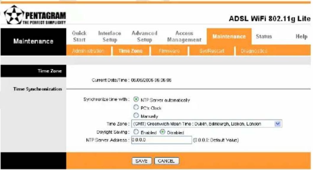
• NTP Server automatically
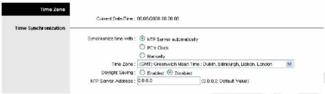
Current Date/Time – This field displays an updated Date and Time when you reenter this menu.
Time Zone – Choose the Time Zone of your location. This will set the time difference between your time zone and Greenwich Mean Time (GMT).
Daylight Saving – Choose "Enabled" or "Disabled" to use daylight savings time.
NTP Server Address – Type the IP address or domain name of your timeserver. Check with your ISP/network administrator if you are unsure of this information.
Click on SAVE to save your changes or on CANCEL to exit without saving.
- PC's Clock
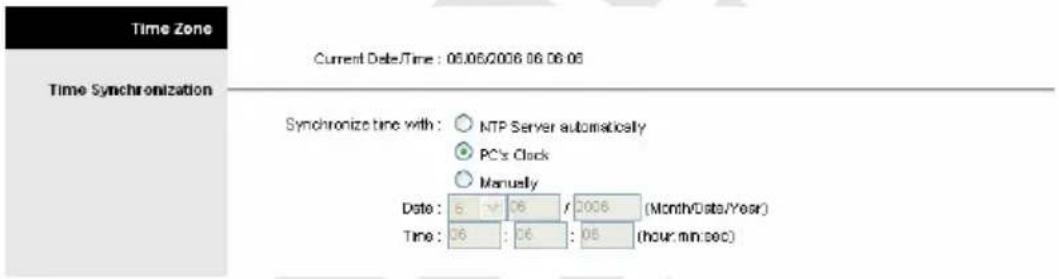
Router will synchronize its clock with computer.
Click on SAVE to save your changes or on CANCEL to exit without saving.
- Manually
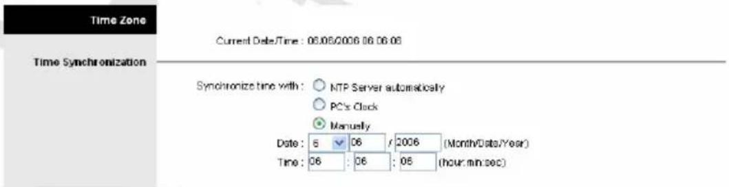
Date – Enter current date.
Time – Enter current time.
Click on SAVE to save your changes or on CANCEL to exit without saving.
Firmware
You can upgrade the firmware of the router in this page. Make sure the firmware you want to use is on the local hard drive of the computer. It might take several minutes, don't power off it during upgrading. Device will restart after the upgrade!! After a success upload, the system automatically restarts. Please wait for the device to finish restarting. This should take about 2 minutes or more. You need to log in again if you want to access the device.
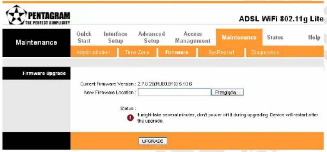
Current Firmware Version – This filed displays the current firmware version.
New Firmware Location – Type in the location of the file you want to upload in this field or click Browse... to find it.
Click UPGRADE to begin the upload process.
SysRestart
The SysRestart screen allows you to restart your router with either its current settings still in place or the factory default settings.
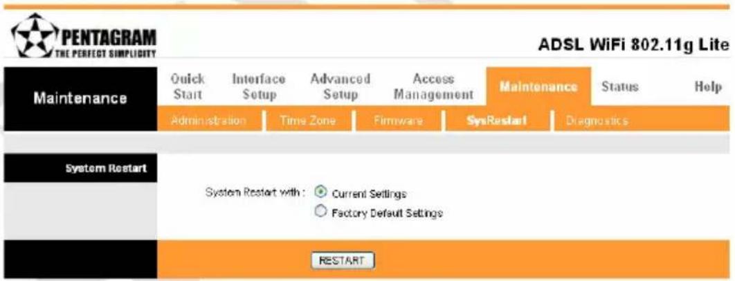
System Restart with – If you wish to restart the router using the factory default settings (for example, after a firmware upgrade or if you have saved an incorrect configuration), select Factory Default Settings to reset to factory default settings. Otherwise, you can select Current Settings. You may also reset your router to factory settings by holding the DEFAULT button on the back panel of your router in for 10-12 second while the router is turned on.
Click RESTART to start this process.
Diagnostics
The Diagnostic Test page shows the test results for the connectivity of the physical layer and protocol layer for LAN & WAN sides.
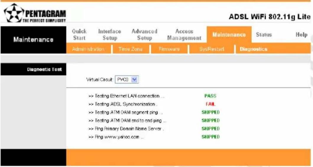
Virtual Circuit – Select which PVC you wish to test from the dropdown list. The router will automatically run diagnostic tests on that circuit. A green PASS means that the given test was passed, a red FAIL means that the test was failed and a green SKIPPED means that the test was skipped.
Status Tab
Device Info
The Device Info screen is a tool that you use to monitor your ADSL Router. It shows the Firmware Version, WAN, LAN, and MAC address information. Note that these fields are read-only and are not meant for diagnostic purposes. Except the Virtual Circuit, click the drop-down list and select the name of the Virtual Circuit on which the system status is to be shown.
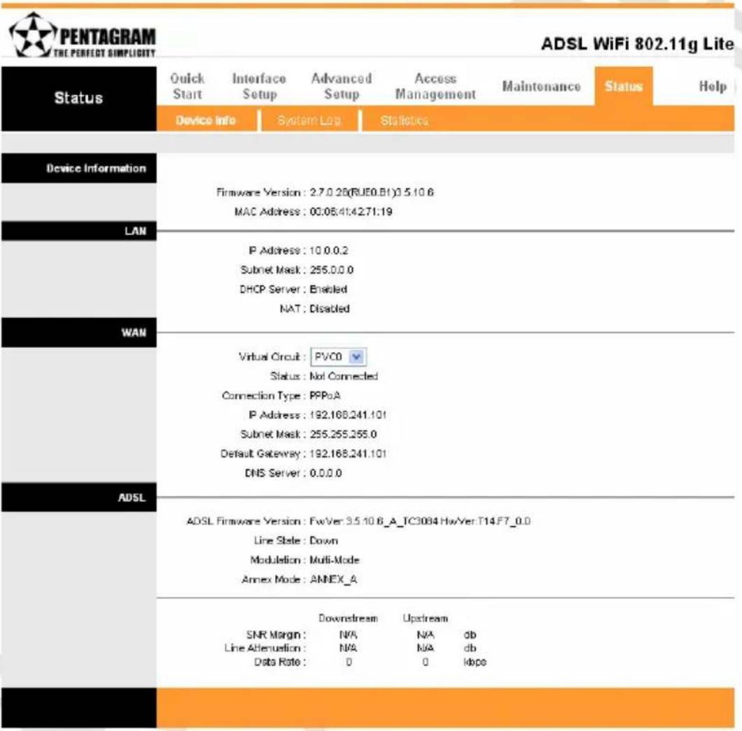
• Device Information
Device Information
Firmware Version: 2.7.0.28(RJE0.B1)35106
MAC Address: 00:08:41:4271:19
Firmware Version – This filed displays current firmware version.
MAC Address – The MAC (Media Access Control) or Ethernet address unique to your modem.
• LAN
LAN
P Address: 10.0.0.2
Subnet Mask: 255.0.0.0
DHCP Server : Enabled
NAT: Disabled
IP Address – The LAN port IP address.
Subnet Mask – The LAN port IP subnet mask.
DHCP Server – The status of DHCP Server (Enabled or Disabled).
NAT – The status of NAT Service (Enabled or Disabled).
• WAN
WAN
Virtual Circuit: PVC0
Status: Not Connected
Connection Type: PPPoA
P Address: 192.168.241.101
Subnet Mask: 255.255.255.0
Default Gateway: 192.168.241.101
DNS Server: 0.0.0.0
Virtual Circuit – Click the drop-down list and select the name of the Virtual Circuit on which the system status is to be shown.
Status – Connected or Not Connected.
Connection Type – The WAN Connection Type.
IP Address / Subnet Mask / Default Gateway / DNS Server – Connection parameters.
- ADSL
ADSL
ADSL Firmware Version: FwVer:3.5.10.6_A_TC3084 HwVer:T14.F7_0.0
Line State : Down
ADSL Firmware Version – This field displays current ADSL firmware version.
Line State – This field displays the ADSL connection process and status.
Modulation - This field displays the ADSL modulation status for G.dmt or T1.413.
Annex Mode - This field displays the ADSL annex modes for Annex A.
Downstream / Upstream – Status of SNR Margin, Line Attenuation and Data Rate:
- SNR Margin – Amount of increased noise that can be tolerated while maintaining the designed BER (bit error rate). The SNR Margin is set by Central Office DSLAM. If the SNR Margin is increased, bit error rate performance will improve, but the data rate will decrease. Conversely, if the SNR Margin is decreased, bit error rate performance will decrease, but the data rate will increase.
- Line Attenuation – Attenuation is the decrease in magnitude of the ADSL line signal between the transmitter (Central Office DSLAM) and the receiver (Client ADSL Modem), measured in dB. It is measured by calculating the difference in dB between the signal power level received at the Client ADSL Router and the reference signal power level transmitted from the Central Office DSLAM.
• Data Rate – This field displays the ADSL data rate.
System Log
The System Log displays data generated or acquired by routine system communication with other devices, such as the results of negotiations with the ISP's computers for DNS and gateway IP addresses. The device keeps a running log of events and activities occurring on the Router. You can click Save Log to display a Windows File Download dialog box that enables opening or saving the contents of the log to your PC. To remove all entries from the list, click Clear Log. New entries will begin accumulating. If the device is rebooted, the logs are automatically cleared.

PENTAGRAM
THE PERFECT SIMPLICITY
ADSL WiFi 802.11g Lite
Status
Quick
Start
Interface
Setup
Advanced
Setup
Access
Management
Maintenance
Status
Help
Denise Info
System Log
9
System Log
1/1/2000 0:0:1> MPOA Link Down
1/1/2000 0:0:1> LAN promiscuous mode <1>
1/1/2000 0:0:1> Last errorlog repeat 2 Times
1/1/2000 0:0:1> SNMP TRAP 0: cold start
1/1/2000 0:0:1> main: init completed
1/1/2000 0:0:2> SNMP TRAP 3: link up
1/1/2000 0:0:2> Last errorlog repeat 1 Times
1/1/2000 0:0:2> adjtime task pause 1 day
1/1/2000 0:0:4> Exception occurred, EPC-80181ae9 ,PA
60161a30
1/1/2000 0:0:5> MPOA Link Down
1/1/2000 0:0:5> LAN promiscuous mode <1>
1/1/2000 0:0:5> Last errorlog repeat 2 Times
1/1/2000 0:0:5> SNMP TRAP 1: warm start
1/1/2000 0:0:5> main: init completed
1/1/2000 0:0:6> SNMP TRAP 3: link up
1/1/2000 0:0:6> Last errorlog repeat 1 Times
1/1/2000 0:0:6> adjtime task pause 1 day
CLEAR LOG
SAVELOG
Statistics
The ADSL Router keeps statistic of traffic that passes through it. You are able to view the amount of packets that passes through the Router on both the WAN port & the LAN port. The traffic counter will reset if the device is rebooted. You can select Ethernet/ADSL to view the statistics report of LAN/WAN.
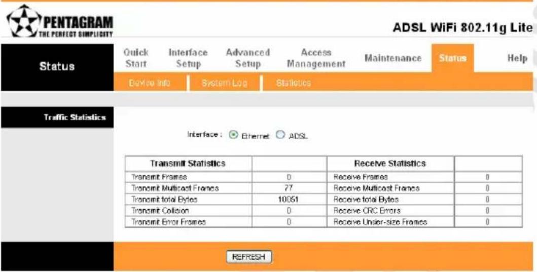
- Ethernet
The Ethernet screen gives you information on how much data your router has transmitted and received across the Ethernet connection.
Traffic Statistics
Interface: Ethernet ADSL
| Transmit Statistics | Receive Statistics | ||
| Transmit Frames | 0 | Receive Frames | 0 |
| Transmit Multicast Frames | 77 | Receive Multicast Frames | 0 |
| Transmit total Bytes | 10051 | Receive total Bytes | 0 |
| Transmit Collision | 0 | Receive CRC Errors | 0 |
| Transmit Error Frames | 0 | Receive Under-size Frames | 0 |
Click on REFRESH to update the screen.
- ADSL
The ADSL screen gives you information about how much data your router has transmitted or received across the ADSL connection.
Traffic Statistics
Interface: Ethernet ADSL
| Transmit Statistics | Receive Statistics | ||
| Transmit total PDUs | 0 | Receive total PDUs | 0 |
| Transmit total Error Counts | 0 | Receive total Error Counts | 0 |
Click on REFRESH to update the screen.
Help Tab
Router's online help.
| Help | Quick Start | Interface Setup | Advanced Setup | Access Management | Maintenance | Status | Help |
| Quick Start | |||||||
| Quick Start | |||||||
| Interface Setup | |||||||
| Internet Settings LAN Settings Wireless LAN Settings | |||||||
| Advanced Setup | |||||||
| Firewall Routing NAT ADSL | |||||||
| Access Management | |||||||
| ACL IP Filter SNMP UPnP DDNS | |||||||
| Maintenance | |||||||
| Administration Time Zone Firmware SysRestart Diagnostics | |||||||
| Status | |||||||
| Device Info System Log Statistics | |||||||
Troubleshooting
If the router is not function properly, first check this session for simple troubleshooting before contacting your Internet service provider (ISP) for support.
Using LEDs to Diagnose Problems
The LEDs are useful aides for finding possible problem causes.
Power LED
The PWR LED on the front panel does not light up.:
- Make sure that the power adaptor is connected to the router and plugged in to an appropriate power source. Use only the supplied power adaptor;
- Check that the router and the power source are both turned on and the router is receiving sufficient power;
- Turn the router off and on;
- If the error persists, you may have a hardware problem. In this case, you should contact your vendor.
LAN LED
The LAN LED on the front panel does not light up.:
- Check the Ethernet cable connections between your router and the computer or hub;
- Check for faulty Ethernet cables;
- Make sure your computer's Ethernet card is working properly;
- If these steps fail to correct the problem, contact your local distributor for assistance.
ADSL LED
The ADSL LED on the front panel does not light up:
- Check the telephone wire and connections between the router ADSL port and the wall jack;
- Make sure that the telephone company has checked your phone line and set it up for ADSL service;
- Reset your ADSL line to reinitialize your link to the DSLAM;
- If these steps fail to correct the problem, contact your local distributor for assistance.
Problems with the Web Interface
I cannot access the web Interface:
- Make sure you are using the correct IP address of the router. Check the IP address of the router;
- Make sure that there is not a console session running;
-
Check that you have enabled web service access. If you have configured a secured client IP address, your computer's IP address must match it. Refer to the chapter on remote management for details;
-
For WAN access, you must configure remote management to allow server access from the WAN (or all);
- Your computer's and the router's IP addresses must be on the same subnet for LAN access;
- If you changed the router's LAN IP address, then enter the new one as the URL;
- Remove any filters in LAN or WAN that block web service.
The web Interface does not display properly:
- Make sure you are using Internet Explorer 5.0 (or compatible) and later versions;
- Delete the temporary web files and log in again.
Problems with the Login Username and Password
I forgot my login username and/or password:
-
The default username is "admin". The default password is "trendchip". The Password and Username fields are case-sensitive. Make sure that you enter the correct password and username using the proper casing;
-
Press the DEFAULT button for five seconds, and then release it. When the ADSL LED begins to blink, the defaults have been restored and the router restarts;
Problems with LAN Interface
I cannot access the router from the LAN or ping any computer on the LAN:
-
Check the Ethernet LEDs on the front panel. A LAN LED should be on for a port that has a PC connected. If it is off, check the cables between your router and the PC. Make sure you have uninstalled any software firewall for troubleshooting;
-
Make sure that the IP address and the subnet mask is consistent between the router and the workstation.
Problems with WAN Interface
Initialization of the ADSL connection failed:
- Check the cable connections between the ADSL port and the wall jack. The ADSL LED on the front panel of the router should be on;
- Check that your VPI, VCI, type of encapsulation and type of multiplexing settings are the same as what you collected from your telephone company and ISP;
- Restart the router. If you still have problems, you may need to verify your VPI, VCI, type of encapsulation and type of multiplexing settings with the telephone company and ISP.
I cannot get a WAN IP address from the ISP:
-
Ensure that all other devices connected to the same telephone line as your router (e.g. telephones, fax machines, analogue modems) have a line filter connected between them and the wall socket (unless your are using a Central Splitter or Central Filter installed by the qualified and licensed electrician), and ensure that all line filters are correctly installed and right way around;
-
Missing line filters or line filters installed the wrong way around can cause problems with your ADSL connection, including causing frequent disconnects.
Frequent loss of ADSL line sync (disconnections):
- The ISP provides the WAN IP address after authenticating you. Authentication may be through the user name and password, the MAC address or the host name;
- The username and password apply to PPPoE and PPPoA encapsulation only. Make sure that you have entered the correct Service Type, User Name and Password (be sure to use the correct casing).
Problems with the Internet Access
I cannot access the Internet:
- Make sure the router is turned on and connected to the network;
- If the ADSL LED is off, refer to Section ADSL LED of this troubleshooting;
- Verify your WAN settings;
- Make sure you entered the correct user name and password;
- For wireless stations, check that both the router and wireless station(s) are using the same ESSID, channel and WEP keys (if WEP encryption is activated).
Internet connection disconnects:
- If you use PPPoA or PPPoE encapsulation, check the idle time-out setting;
- Contact your ISP.
If you have any troubles to configure or setup this ADSL Ethernet Router, please feel free to contact us.
NOTES
- Installation and User's Manual
- PENTAGRAM Cerberus ADSL Wi-Fi Lite
- INDEX
- INTRODUCTION 5
- PRODUCT OVERVIEW....7
- CONFIGURE ROUTER VIA WEB BROWSER.... 13
- TROUBLESHOOTING....51
- Introduction
- Package Contents
- Features
- Product Overview
- Important Notes
- Front LEDs
- The Rear Ports
- Default Settings
- Resetting router
- Connecting Cerberus to Computer.
- Connecting via Ethernet Port (Ethernet Card)
- Connecting via WLAN Interface (Wireless Card)
- Configure TCP/IP
- Windows 2000/XP
- Windows 95/98/Me
- Windows NT
- Configure router via web browser
- Login
- Navigation
- Quick Start Wizard
- Setting a New Password
- Choose your Time Zone
- Set your Internet Connection
- Glossary:
- PENTAGRAM HE PERFECT SIMPLICITY
- • Dynamic IP Address
- - Static IP Address
- - PPPoE/PPPoA
- - Bridge Mode
- Finishing the Wizard
- Interface Setup Tab
- Internet
- • ATM VC
- - Encapsulation
- - PPPoA/PPPoE
- LAN
- - Router Local IP
- • DHCP
- Relay
- Wireless
- - Wireless LAN
- • WEP
- - WPA-PSK
- - Advanced Setting
- - Wireless MAC Address Filter
- Advanced Setup Tab
- Firewall
- Routing
- Deet IP Mask Gateway IP Metric Device Use Edit Drop
- NAT
- What NAT Does
- How NAT Works
- NAT Mapping Types
- Cerberus ADSL Wi-Fi Lite
- • DMZ
- - Virtual Server
- - IP Address Mapping
- ADSL
- Access Management Tab
- ACL
- UWAGA!
- IP Filter
- Active Src IP/Mask Dest IP/Mask Src Port Dest Port Protocol Unmatched
- SNMP
- UPnP
- DDNS
- Maintenance Tab
- Administration
- Time Zone
- • NTP Server automatically
- - PC's Clock
- - Manually
- Firmware
- SysRestart
- Diagnostics
- Status Tab
- Device Info
- • Device Information
- • LAN
- • WAN
- WAN
- - ADSL
- System Log
- Statistics
- - Ethernet
- Traffic Statistics
- Help Tab
- Troubleshooting
- Using LEDs to Diagnose Problems
- Power LED
- LAN LED
- ADSL LED
- Problems with the Web Interface
- Problems with the Login Username and Password
- Problems with LAN Interface
- Problems with WAN Interface
- Problems with the Internet Access
- NOTES
Brand : Pentagram
Model : Cerberus ADSL Wi-Fi Lite
Category : Router