DN-16110 - Headphones Digitus - Free user manual and instructions
Find the device manual for free DN-16110 Digitus in PDF.

| Product Type | Wired Over-Ear Headphones with Microphone |
| Brand | Digitus |
| Model | DN-16110 |
| Driver Diameter | 40 mm |
| Impedance | 32 Ohm |
| Frequency Response | 20 Hz - 20 kHz |
| Sensitivity | 108 dB |
| Connection Type | 3.5mm Audio Jack with Microphone |
| Cable Length | 2.0 m |
| Microphone Type | In-Line Omnidirectional |
| Dimensions (W x D x H) | Approx. 180 x 80 x 200 mm |
| Weight | Approx. 200 g |
| Power Supply | No battery required (wired) |
| Playback Control | In-line volume control and mute switch |
| Compatibility | PC, laptop, smartphone, tablet with 3.5mm combo jack |
| Cleaning and Maintenance | Wipe with a dry soft cloth; avoid liquids and solvents |
| Safety Warnings | Do not use at high volumes for extended periods to prevent hearing damage |
| Spare Parts and Repairability | Ear pads and cable may be replaceable; contact support for parts |
| Package Contents | Headphones, user manual |
Frequently Asked Questions - DN-16110 Digitus
User questions about DN-16110 Digitus
0 question about this device. Answer the ones you know or ask your own.
Ask a new question about this device
Download the instructions for your Headphones in PDF format for free! Find your manual DN-16110 - Digitus and take your electronic device back in hand. On this page are published all the documents necessary for the use of your device. DN-16110 by Digitus.
USER MANUAL DN-16110 Digitus
All lead-free products offered by the company comply with the requirements of the European law on the Restriction of Hazardous Substances (RoHS) directive, which means our manufacture processes and products are strictly “lead-free” and without the hazardous substances cited in the directive.

The crossed-out wheeled bin mark symbolizes that within the European Union the product must be collected separately at the product end-of-life. This applies to your product and any peripherals marked with this symbol. Do not dispose of these products as unsorted municipal waste. Contact your local dealer for procedures for recycling this equipment.

This is a class A product. In a domestic environment this product may cause radio interference in which case the user may be required to take adequate measures.
Federal Communications Commission Interference Statement
This equipment has been tested and found to comply with the limits for a Class A digital device, pursuant to Part 15 of the FCC Rules. These limits are designed to provide reasonable protection against harmful interference when the equipment is operated in a commercial environment. This equipment generates, uses, and can radiate radio frequency energy and, if not installed and used in accordance with the instruction manual, may cause harmful interference to radio communications. Operation of this equipment in a residential area is likely to cause harmful interference in which case the user will be required to correct the interference at his own expense.
This device complies with Part 15 of the FCC Rules. Operation is subject to the following two conditions:
(1) This device mat not cause harmful interference, and
(2) This device must accept any interference received, including interference that may cause undesired operation.
Trademark Acknowledgements
iPad® & iPhone® are the registered trademarks of Apple Inc.
Android ^™ is a trademark of Google Inc. Use of this trademark is subject to Google Permissions.
Microsoft®, Windows® & Internet Explorer® are registered trademarks of Microsoft Corporation in the United States and/or other countries.
Disclaimer
We reserve the right to revise or remove any content in this manual at any time. We do not warrant or assume any legal liability or responsibility for the accuracy, completeness, or usefulness of this manual. The content of this manual is subject to change without notice.
This product doesn't have a standby / shutdown mode.
MPEG4 Licensing
THIS PRODUCT IS LICENSED UNDER THE MPEG4 VISUAL PATENT PORTFOLIO LICENSE FOR THE PERSONAL AND NON-COMMERCIAL USE OF A CONSUMER FOR (i) ENCODING VIDEO IN COMPLIANCE WITH THE MPEG4 VISUAL STANDARD ("MPEG-4 VIDEO") AND/OR (ii) DECODING MPEG4 VIDEO THAT WAS ENCODED BY A CONSUMER ENGAGED IN A PERSONAL AND NON-COMMERCIAL ACTIVITY AND/OR WAS OBTAINED FROM A VIDEO PROVIDER LICENSED BY MPEG LA TO PROVIDE MPEG4 VIDEO. NO LICENSE IS GRANTED OR SHALL BE IMPLIED FOR ANY OTHER USE. ADDITIONAL INFORMATION INCLUDING THAT RELATING TO PROMOTIONAL INTERNAL AND COMMERCIAL USES AND LICENSING MAY BE OBTAINED FROM MPEG LA, LLC. SEE HTTP://WWW.MPEGLA.COM.
GPL Licensing

This product contains codes which are developed by Third-Party-Companies and which are subject to the GNU General Public License (“GPL”) or the GNU Lesser Public License (“LGPL”).
The GPL Code used in this product is released without warranty and is subject to the copyright of the corresponding author.
Further source codes which are subject to the GPL-licenses are available upon request.
We are pleased to provide our modifications to the Linux Kernel, as well as a few new commands, and some tools to get you into the code. The codes are provided on the FTP site, and please download them from the following site or you can refer to your distributor:
TABLE OF CONTENTS
1. HARDWARE OVERVIEW.... 1
1.1 Front Panel....1
1.2 Rear Panel .... 1
2. CONNECTION.... 2
2.1 Hard disk installation....2
2.2 Simple Connection Diagram....3
2.3 Camera IP Configurations by LAN 4
2.3.1 Automatically ....4
2.3.2 Manually 4
3. USER INTERFACE....5
3.1 Local....5
3.1.1 NVR Status....5
3.1.2 Channel Status....5
3.1.3 Quick Operation 6
3.1.4 Main Menu....6
3.1.5 Playback Panel 6
3.2 Remote....7
4. FREQUENTLY-USED FUNCTIONS 8
4.1 Key Lock / Unlock 8
4.2 Channel Selection....8
4.3 IP Device Search....9
4.4 User Level Creation 10
4.5 Event Search....11
4.6 Video Backup....12
4.7 Video Playback on PC....12
4.7.1 Convert the file format to AVI 12
5. QUICK OPERATION.... 13
5.1 Power Switch 13
5.2 Channel Selection....13
5.3 Digital Zoom....13
5.4 PTZ Control....14
5.5 IP Device Search....14
6. MAIN MENU 16
6.1 QUICK START 16
6.1.1 GENERAL....16
6.1.2 TIME SETUP....17
6.1.3 BENCHMARK 18
6.2 SYSTEM 18
6.2.1 ACCOUNT....18
6.2.2 TOOLS 19
6.2.3 SYSTEM INFO....19
6.2.4 BACKUP DATA (USB)....20
6.2.5 BACKUP LOG (USB) 21
6.3 EVENT INFORMATION 22
6.3.1 QUICK SEARCH....22
6.3.2 EVENT SEARCH ....22
6.3.3 HDD INFO 23
6.3.4 EVENT LOG....23
6.4 ADVANCED CONFIG....23
6.4.1 CONNECTION 23
6.4.2 CAMERA....24
6.4.3 DETECTION....25
6.4.4 ALERT 26
6.4.5 NETWORK 27
6.4.6 DISPLAY 27
6.4.7 RECORD....28
6.4.8 NOTIFY 29
6.5 SCHEDULE SETTING 29
6.5.1 RECORD....29
6.5.2 EVENT 30
APPENDIX 1 MOBILE SURVEILLANCE VIA EAGLEEYES 31
A2.1 Prerequisites....31
A2.2 Where to download....31
APPENDIX 2 COMPATIBLE USB FLASH DRIVE LIST 32
APPENDIX 3 COMPATIBLE HARD DISK LIST .... 33
APPENDIX 4 BATTERY REPLACEMENT 34
APPENDIX 5 SPECIFICATIONS .... 35
1. HARDWARE OVERVIEW
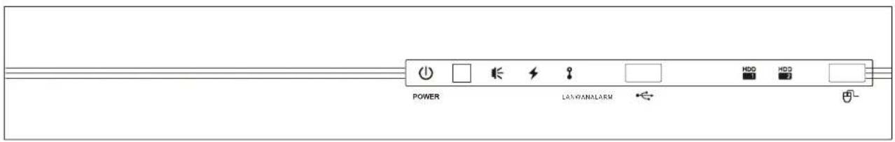
1.1 Front Panel
text_image
POWER LANWANALARM HDD HDD1) LED indicators
| 1 | The NVR is power-supplied. |
| 2 | An alarm event occurs. |
| 3 | The NVR is connected to Internet. |
| 4 | The NVR is connected to LAN. |
HDD Up to two hard disks are installed in the NVR and connected well.
2) USB port
Insert a compatible USB flash drive for video backup.
Note: For the compatible list of USB flash drives, please refer to "APPENDIX 2 COMPATIBLE USB FLASH DRIVE LIST" at page 32.
3) Mouse port (θ)
Insert a mouse for function operation.
1.2 Rear Panel

text_image
AUDIO OUT WAN INTERNET HOME LAN SWITCH + - DOWN IN WARNING: TO REDUCE THE RISK OF ELECTRIC SHOCK DO NOT REMOVE COVER OR BACK; NO LUX-SEVEN/KEABLE PARTS HERE. REFER SERVICEING TO QUALIFIED SERVICE PERSONNEL1) AUDIO OUT
Connect to a speaker.
2) WAN
This port is used to connect your NVR to Internet via a RJ45 network cable.
3) HDMI
This port is used to connect the monitor which supports HDMI interface for high definition video output.
Note: Direct connection to the monitor which supports VGA or composite interface is not supported. Please prepare a converter in advance.
4) LAN
This port is used to connect your NVR to our brand's IP cameras locally.
5) DC19V IN
Connect the NVR to power with the regulated adapter.
6) (Power switch)
Switch to “-” to turn on the power, and “O” to turn off the power.
2. CONNECTION
2.1 Hard disk installation
Step1: Remove the top cover.
Step2: Find the hark disk bracket in the DVR, and place the compatible hark disk in the bracket.
Step3: With the PCB side facing up, connect the hard disk to the power connector and data connector.
Step4: Fasten the hark disk with the supplied screws, two for each side.

text_image
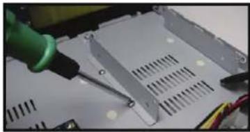
Connect to power and data connectors Fasten hard disk to bracketStep5: To install another hard disk, find the supplied hard disk brackets in the package, and fix them onto the NVR base.
natural_image
Close-up of a green tool applying plastic to a white electronic component with visible slots and wiring (no text or symbols)Step6: With the PCB side facing up, connect the hard disk to the power connector and data connector.
Step7: Then, put the hard disk in the bracket, and fasten it with the supplied screws, two for each side.
Step8: Replace the top cover and fasten the screws you loosened in Step1.
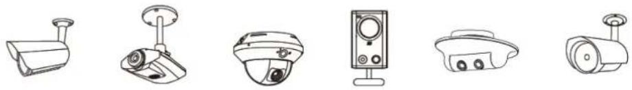
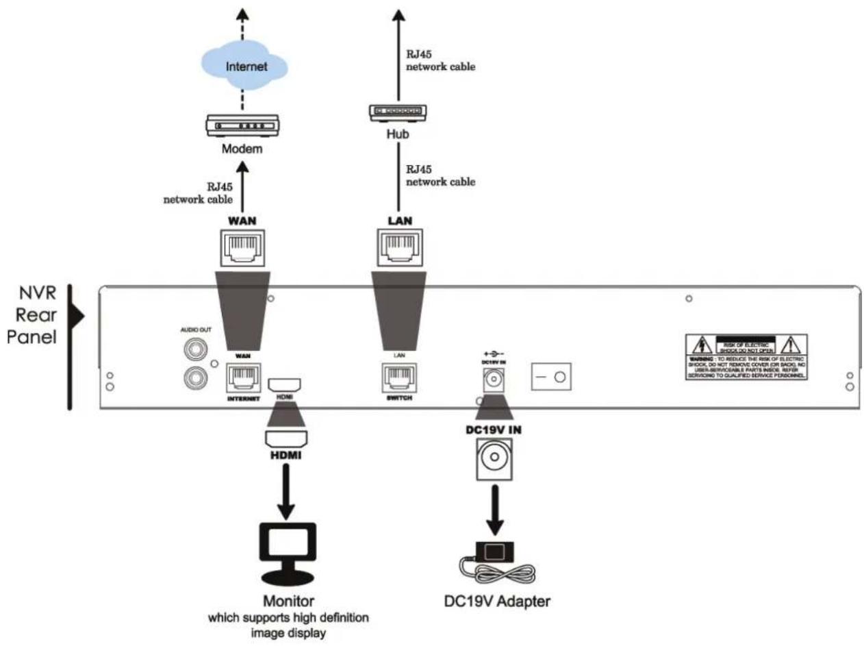
2.2 Simple Connection Diagram
Note: It's recommended to power on the NVR after the IP cameras are connected and powered on. This ensures the auto IP configuration works well.
Connect up to 6 IP devices:
natural_image
Line drawings of six different surveillance cameras and a central display unit (no text or symbols)Remote connection\*\*
- Enter the IP address and access information of the IP camera or DVR in the NVR.
- Wait till you can see images on the monitor.
Local connection\*
- Connect the camera to a hub.
- Wait till the camera is configured automatically and you will see camera images on the monitor soon.***
flowchart
graph TD
    A["Internet"] --> B["Modem"]
    B --> C["RJ45 network cable"]
    C --> D["WAN"]
    D --> E["INTERNET"]
    E --> F["HDMI"]
    F --> G["Monitor which supports high definition image display"]
    H["RJ45 network cable"] --> I["LAN"]
    I --> J["Switch"]
    J --> K["DC19V Adapter"]
    L["DISC19V IN"] --> K
    M["NVR Rear Panel"] --> N["Monitor"]
    style A fill:#cce5ff,stroke:#333
    style H fill:#cce5ff,stroke:#333
    style L fill:#cce5ff,stroke:#333
    style M fill:#cce5ff,stroke:#333
- Local connection only allows monitoring locally. To monitor from anywhere other than the NVR is installed, please connect your NVR to Internet. For details, please refer to "3. NETWORK CONFIGURATIONS".
** Remote connection is available only when the NVR is connected to Internet. To connect your NVR to Internet, please refer to "3. NETWORK CONFIGURATIONS".
*** If you don't see camera images, change the IP address of your camera to "10.1.1.xx" (xx ranges from 11 \~ 253). For details, please refer to "2.2 Camera IP Configurations by LAN".
2.3 Camera IP Configurations by LAN
2.3.1 Automatically
The NVR will automatically configure the IP address of a camera connected by LAN if:
■ The connected IP camera is our brand's IP camera.
■ The default IP configuration method of the camera is "DHCP".
■ The camera is powered on before the NVR is powered on.
If not, you may also configure the IP address of your camera manually as described in "2.3.2 Manually".
2.3.2 Manually
If the NVR doesn't configure the IP address of your camera automatically as described above, your IP camera might NOT be:
■ Our brand's IP camera.
■ Set to "DHCP" as its default IP configuration method.
To solve this, use our brand's IP camera, and reconfigure its IP address to 10.1.1.xx (xx ranges from 11 \~ 253), in the same network segment as the NVR.
a) Select “☐” on the bottom of the screen, You’ll see the list of every connected IP camera with its connection status to this NVR and MAC address.
b) Select the IP address which is not used, and select "SETUP".
| IP SEARCH | ||||
| IP | PORT | MAC | STATUS | |
| 10.1.1.12 88 | 00:0e:53:e5:9a:f1 | BE CONNECTED ON CH1 | ||
| 10.1.1.13 | 88 | 00:0e:53:a6:91:18 | BE CONNECTED ON CH2 | |
| 10.1.2.14 88 | 00:0e:53:a5:9f:a2 | UNUSE | ||
| 10.1.1.15 | 88 | 00:0e:53:e1:4e:k5 | BE CONNECTED ON CH3 | |
| 10.1.1.16 | 88 | 00:0e:53:s5:3e:h6 | BE CONNECTED ON CH4 | |
| 10.1.1.17 | 88 | 00:0e:53:e6:4b:26 | BE CONNECTED ON CH5 | |
| t1 | CONNECT | SETUP EXIT | ||
c) Select "STATIC" in "NETWORK TYPE", and change the IP address to 10.1.1.xx (xx ranges from 11 \~ 253)
d) Click "APPLY" and "EXIT" to save your changes.
| SETUP | ||
| NETWORK TYPE | STATIC | |
| IP | 10.1.1.14 | |
| PORT | 88 | |
| USER NAME | admin | |
| PASSWORD | ***** | |
| NETMASK | 255.0.0.0 | |
| GATEWAY | 10.1.1.10 | |
| PRIMARY DNS | 168.95.1.1 | |
| APPLY | EXIT | |
e) The NVR will then detect the IP camera and display images soon.
3. USER INTERFACE
3.1 Local
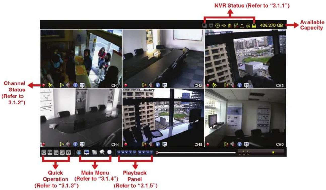
text_image
NVR Status (Refer to "3.1.1") Available Capacity Channel Status (Refer to 3.1.2") Quick Operation (Refer to "3.1.3") Main Menu (Refer to "3.1.4") Playback Panel (Refer to "3.1.5")3.1.1 NVR Status
| Key lock | Key unlock | ||
| Channel lock | Channel unlock | ||
| USB flash drive / device connected | No USB device connected | ||
| Timer record on | Timer record off | ||
| Overwrite on | Overwrite off | ||
| Sequence mode on | Sequence mode off | ||
| PTZ mode on | PTZ mode off | ||
| CPU loading | |||
Network Status:
| (WAN) Internet connected | (WAN) Internet disconnected | ||
| (WAN) Local connection | |||
| (LAN) Auto mode –Mbit/s | (LAN) Auto mode – Gbit/s | ||
| (LAN) DHCP / Static IP mode | (LAN) Camera disconnected | ||
3.1.2 Channel Status
 | Auto search on |  | Auto search off Original S |  | Fit to screen |  | |
 | Live audio on | [WDBA] | Audio off Audio playback | [8TBA] | Audio playback off | [A50A] | |
 | Recording |  | Human detection event |  | Alarm event |  | Motion event |
| [W3AC] | Live information | [4205] | Playback information | ||||
3.1.3 Quick Operation
For details, please refer to "5. QUICK OPERATION" at page 13.
 | Click to show the power off panel to either halt or reboot the system. |
 | Click to show the channel switch panel and select the channel you want. |
 | Switch to the channel you want first, and click 🔒 to enter the zoom-in mode. In this mode, click and drag the red frame on the bottom left of the screen to move to the place you want to see. |
 | Click to enter the PTZ mode and show the PTZ camera control panel. |
 | Click to open the IP search window and check the current connection status of each channel. |
3.1.4 Main Menu
For details, please refer to "6. MAIN MENU" at page 16.
| [BYAW] | QUICK START | Click to set the status display, image settings, and date & time. |
 | SYSTEM | Click to set the system configurations. |
 | EVENT INFORMATION | Click to enter the event search menu. |
 | ADVANCED CONFIG | Click to set CONNECTION, CAMERA, DETECTION, ALERT, NETWORK, DISPLAY, RECORD and NOTIFY. |
| [SW8Z] | SCHEDULE SETTING | Click to set record timer. |
3.1.5 Playback Panel
| [6AAT] | Fast Forward Increase the speed for fast forward from 4X to 32X. |
 | Fast Rewind Increase the speed for fast rewind from 4X to 32X. |
| [7067] | Play / Pause Click to play the latest recorded video clip immediately, and click again to pause.In the pause mode, click ▶ once to get one frame forward, and click ▶ to get one frame rewind. |
| [BAXA] | Stop Click to stop the video playback. |
 | Slow Playback Click once to get 1/4X speed playback, and click twice to get 1/8X speed playback. |
 | Previous / Next Hour Click to jump to the next / previous time interval in an hour, for example, 11:00 ~ 12:00 or 14:00 ~ 15:00, and start playing the earliest event video clip recorded during this whole hour. |
 | Quick Search Click to enter the quick search menu for specific record data search. |
3.2 Remote
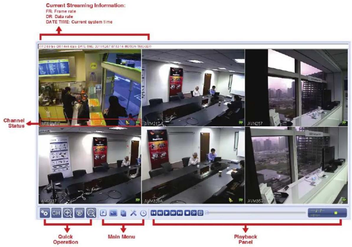
text_image
Current Streaming Information: FR: Frame rate DR: Data rate DATE TIME: Current system time FR 2.03 fps DR 1444 kcps DATE TIME: 20/11/207 07:53:14 MOTION TRIGGER Channel Status AVN217 AVN317 AVN328A AVN257 AVN357A Quick Operation Main Menu Playback Panel4. FREQUENTLY-USED FUNCTIONS
4.1 Key Lock / Unlock
To luck or unlock NVR local operation, click 🔒 (unlock) or 🔒 (lock) on the NVR status bar to change the status to 🔒 (lock) or 🔒 (unlock).
To unlock NVR local operation, you'll be prompted to enter the user level and password to access.
Note: The default user level and password are both "admin".
Note: Different user level has different access privilege for certain NVR functions. For details, please refer to "4.4 User Level Creation" at page 10.
4.2 Channel Selection
Note: Channel switch is available only for "SUPERVISOR". To know more details, please refer to "4.4 User Level Creation" at page 10.
4.3 IP Device Search
Note: This function is available only for "SUPERVISOR". To know more details, please refer to "4.4 User Level Creation" at page 10.
Click 📄 (IP Search) to start search IP camera(s) connected in the same network segment as the NVR (i.e. 10.1.1.xx by default).
You'll see the list of every connected IP camera with its connection status to this NVR and MAC address.
| IP SEARCH | |||
| IP | PORT | MAC | STATUS |
| 10.1.1.12 88 | 00:0e:53:e5:9a:f1 | BE CONNECTED ON CH1 | |
| 10.1.1.13 | 88 | 00:0e:53:a6:91:18 | BE CONNECTED ON CH2 |
| 10.1.1.14 88 | 00:0e:53:a5:9f:a2 | UNUSE | |
| 10.1.1.15 | 88 | 00:0e:53:e1:4e:k5 | BE CONNECTED ON CH3 |
| 10.1.1.16 | 88 | 00:0e:53:s5:3e:h6 | BE CONNECTED ON CH4 |
| 10.1.1.17 | 88 | 00:0e:53:e6:4b:26 | BE CONNECTED ON CH5 |
| 10.1.1.18 | 88 | 00:0e:53:g2:3b:e7 | BE CONNECTED ON CH6 |
| t1 | CONNECT | SETUP EXIT | |
To fix the camera IP address, or allow the NVR to assign an IP address to your IP camera, select "SETUP", and select "STATIC IP" or "DHCP" for "NETWORK TYPE".
Click "APPLY" and "EXIT" to save your changes.
| SETUP | ||
| NETWORK TYPE | DHCP | |
| IP | 10.1.1.14 | |
| PORT | 80 | |
| USER NAME | admin | |
| PASSWORD | ***** | |
| NETMASK | 255.0.0.0 | |
| GATEWAY | 10.1.1.10 | |
| PRIMARY DNS | 168.085.1.1 | |
| APPLY | EXIT | |
To connect to another IP camera, select the unused IP camera from the IP search list, and select "CONNECT". Select the channel you want to display the camera images, and click "SAVE" to start connection.
| CONNECT | ||
| IP | 10.1.1.14 | |
| PORT | 88 | |
| CHANNEL | CH5 | |
| USER NAME | admin | |
| PASSWORD | ***** | |
| SAVE | CANCEL | |
Note: This function is available only for "SUPERVISOR".
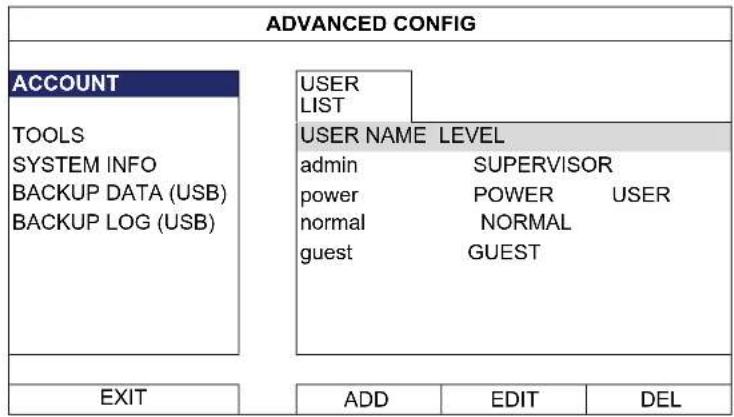
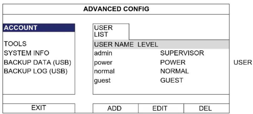
To create different user account for different access privilege, click 📄 (SYSTEM), and select "ACCOUNT" to enter "USER LIST".
text_image
ADVANCED CONFIG ACCOUNT TOOLS SYSTEM INFO BACKUP DATA (USB) BACKUP LOG (USB) USER LIST USER NAME LEVEL admin SUPERVISOR power POWER USER normal NORMAL guest GUEST EXIT ADD EDIT DELDifferent user level has different access privilege for certain functions as described below:
| Function | User Level | |
| ■ NVR status | ||
 | Key lock / unlock SUPERVISOR / POWER / NORMAL | |
 | Channel switch lock / unlock | SUPERVISOR |
| ■ Channel status | ||
 | Auto search on / off | SUPERVISOR |
 | Live audio on / off | SUPERVISOR |
 | Playback audio on / off | SUPERVISOR |
 | Original size / Fit to screen | SUPERVISOR |
 | Live / Playback information | SUPERVISOR |
| ■ Quick operation | ||
 | Power | SUPERVISOR |
 | Channel Switch | SUPERVISOR / POWER / NORMAL / GUEST |
 | Digital Zoom | SUPERVISOR / POWER / NORMAL / GUEST |
 | PTZ Control | SUPERVISOR / POWER |
 | IP Search | SUPERVISOR |
| ■ Main menu | ||
 | Quick Start | SUPERVISOR |
 | System | SUPERVISOR |
 | Event Information | SUPERVISOR |
 | Advanced Config. | SUPERVISOR |
 | Schedule Setting | SUPERVISOR |
| Function | User | Level | ||
| ■ Playback control | ||||
 | Fast Forward SUPERVISOR / POWER / NORMAL | |||
| Fast Rewind SUPERVISOR / POWER / NORMAL | ||||
 | Play / Pause SUPERVISOR / POWER / NORMAL | |||
 | Stop SUPERVISOR / POWER / NORMAL | |||
| Slow Playback SUPERVISOR / POWER / NORMAL | ||||
 | Previous / Next Hour SUPERVISOR / POWER / NORMAL | |||
 | Quick Search SUPERVISOR / POWER / NORMAL | |||
4.5 Event Search
Note: This function is not available for "GUEST". For details, please refer to "4.4 User Level Creation" at page 10.
In the playback control bar, click 📄 to enter the search list.
EVENT INFORMATION
text_image
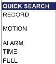
QUICK SEARCH RECORD MOTION ALARM TIME FULLHARD DISK ALL HDD CHANNEL

line
| Day | Time | Duration | |---|---|---| | SUN | 1 | 1 | | SUN | 8 | 8 | | SUN | 15 | 15 | | SUN | 22 | 22 | | SUN | 29 | 29 | | 2009 | 1 | 1 | | 2009 | 2 | 2 | | 2009 | 9 | 9 | | 2009 | 16 | 16 | | 2009 | 23 | 23 | | TUE | 3 | 3 | | TUE | 17 | 17 | | TUE | 24 | 24 | | NOV | WED | 4 | | NOV | THU | 5 | | NOV | FRI | 6 | | NOV | SAT | 7 | | NOV | 10 | 10 | | NOV | 11 | 11 | | NOV | 18 | 18 | | NOV | 19 | 19 | | NOV | 26 | 26 | | NOV | 20 | 20 | | NOV | 27 | 27 | | NOV | 21 | 21 | | NOV | 28 | 28 | | 15 : 20 | 00:00 to 24:00 | 06:00 to 18:00 | | SUBMIT | 06:00 to 24:00 | 12:00 to 18:00 |■ To quickly search the time within which might include the recorded data you want to see:
- Select the channel(s) and month you want to search. You'll see the date(s) with recorded data is highlighted.
- Select the date you want to search. You'll see the time with recorded data is highlighted from the timeline bar.
- Click the time to start playback.
■ To search the recorded data by event, select RECORD / MOTION / ALARM / TIME, or select FULL to show all the event logs. Select the log you want to start playback.
Note: During video playback, you might click ⓘ to check the recorded data details, or click 🔒 to play the recorded audio (if any) on the channel you want.
4.6 Video Backup
Note: This function is available for "SUPERVISOR". For details, please refer to "4.4 User Level Creation" at page 10.
Note: Before using the USB flash drive, please use your PC to format the USB flash drive to FAT32 format first. For the list of compatible USB flash drives, please refer to "APPENDIX 2 COMPATIBLE USB FLASH DRIVE LIST at page 32.
To copy recorded data for video backup, click 📄 (SYSTEM), and select "BACKUP DATA (USB)".
| SYSTEM | |
| ACCOUNT TOOLS SYSTEM INFO BACKUP DATA (USB) BACKUP LOG (USB) | START DATE 2009/NOV/19 START TIME 08:30:21 END DATE 2009/NOV/19 END TIME 17:59:29 CHANNEL ☑ 01 ☐ 02 ☐ 03 ☐ 04 ☑ 05 ☐ 06 HARD DISK ALL HDD BACKUP REQUIRE SIZE: 554MB SUBMIT SUBMIT |
| EXIT | AVAILABLE SIZE: 3788.0MB |
Step1: Select the time within which includes the video data you want to backup.
Step2: Select the channel(s) within which includes the video data you want to backup.
Step3: In "REQUIRE SIZE", select "SUBMIT" to know the file size of the selected data.
Step4: In "BACKUP", select "SUBMIT" to start backup to your USB flash drive, and wait till the backup successful message appears.
4.7 Video Playback on PC
The backup file is the unique video format for security reasons, and you can only use our own player to play.
To play video backup on your PC:
Step1: Insert the USB flash drive with recorded data into your PC.
Note: The supported PC operating systems are Windows 7, Vista & XP.
Step2: Find the program "PLAYER.EXE" in the USB flash drive, and double-click it to install.
Step3: Run the program, VideoPlayer_NVR, and browse to where you save the recorded data.
Step4: Select the file you want to start video playback.
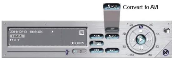
4.7.1 Convert the file format to AVI
To convert the video file format to AVI, click "AVI" from the playback panel to start file conversion.
Note: The recorded audio (if any) will be removed when the file format is converted to AVI.
text_image
Convert to AVI 2011/12/13 19:04:04 FRAME 00:03:35 -2K -4X -8X -16X 10X CSD AVI5. QUICK OPERATION
5.1 Power Switch

Note: This function is available only for "SUPERVISOR". To know more details, please refer to "4.4 User Level Creation" at page 10.
To power off or reboot the NVR, you may:
■ Turn the power switch ( -0 ) directly on the NVR rear panel (refer to "1.2 Rear Panel" at page 1), or
■ Go to, and select (power off) or (reboot).

flowchart
graph LR
    A["HALT THE SYSTEM"] --> B["Power Light Icon"]
    B --> C["Power Light Icon"]
    C --> D["Reboot THE SYSTEM"]
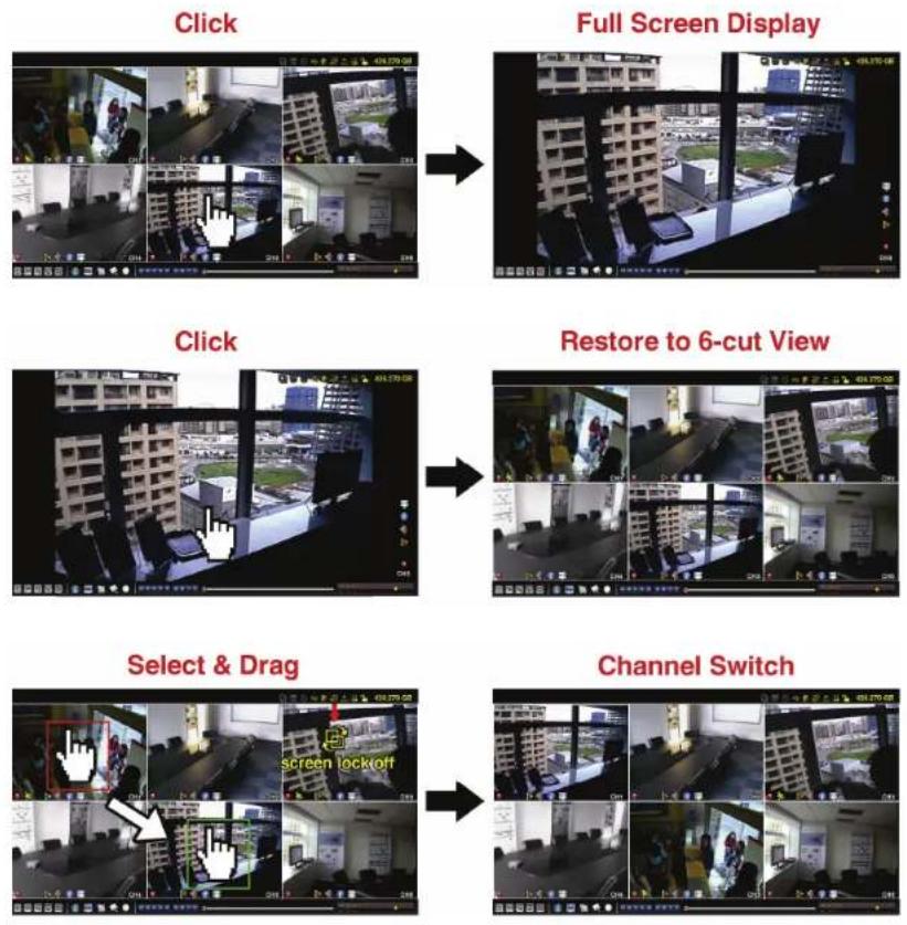
5.2 Channel Selection

To display a specific channel in full screen and restore to the 6-cut view, you may:
■ Directly click the channel you want on the screen, and click it twice to restore to the 6-cut view (refer to "4.2 Channel Selection" at page 8), or
- Go to CH, and select the channel you want to display in full screen from 1 \~ 6, and select to restore to the 6-cut view.

text_image
CONTROL PANEL 1 2 3 4 5 6 7 8 9 10 11 12 13 14 15 165.3 Digital Zoom

Switch to the channel you want to zoom in, and click 🔒 to enter the zoom-in mode. In this mode, click and drag the red frame on the bottom left of the screen to move to the place you want to see.
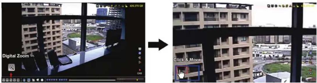
text_image
Digital Zoom Click & MoveNote: This function is available only for "SUPERVISOR" and "POWER USER". To know more details, please refer to "4.4 User Level Creation" at page 10.
Click 📄 on the quick menu bar to display the panel as follows:

text_image
Screenshot of a software toolbar with icons for file operations, navigation, play, and editing functions |
5.5 IP Device Search
Note: This function is available only for "SUPERVISOR". To know more details, please refer to "4.4 User Level Creation" at page 10.
Click (IP Search) to start search IP camera(s) connected in the same network segment as the NVR (i.e. 10.1.1.xx by default).
You'll see the list of every connected IP camera with its connection status to this NVR and MAC address.
| IP SEARCH | |||||
| IP | PORT | MAC | STATUS | ||
| 10.1.1.12 | 88 00:0e:53:e5:9a:f1 | BE CONNECTED ON CH1 | |||
| 10.1.1.13 | 88 | 00:0e:53:a6:91:18 | BE CONNECTED ON CH2 | ||
| 10.1.1.14 | 88 00:0e:53:a5:9f:a2 | UNUSE | |||
| 10.1.1.15 | 88 | 00:0e:53:e1:4e:k5 | BE CONNECTED ON CH3 | ||
| 10.1.1.16 | 88 | 00:0e:53:s5:3e:h6 | BE CONNECTED ON CH4 | ||
| 10.1.1.17 | 88 | 00:0e:53:e6:4b:26 | BE CONNECTED ON CH5 | ||
| 10.1.1.18 | 88 | 00:0e:53:g2:3b:e7 | BE CONNECTED ON CH6 | ||
| t) | CONNECT | SETUP | EXIT | ||
To fix the camera IP address, or allow the NVR to assign an IP address to your IP camera, select "SETUP", and select "STATIC IP" or DHCP for "NETWORK TYPE".
Click "APPLY" and "EXIT" to save your changes.
| SETUP | ||
| NETWORK TYPE | DHCP | |
| IP | 10.1.1.14 | |
| PORT | 00080 | |
| USER NAME admin | ||
| PASSWORD | ***** | |
| NETMASK | 255.0.0.0 | |
| GATEWAY | 10.1.1.10 | |
| PRIMARY DNS 168.085.1.1 | ||
| APPLY | EXIT | |
To connect to another IP camera, select the unused IP camera from the IP search list, and select "CONNECT". Select the channel you want to display the camera images, and click "SAVE" to start connection.
| CONNECT | ||
| IP | 10.1.1.14 | |
| PORT | 88 | |
| CHANNEL | CH5 | |
| USER NAME admin | ||
| PASSWORD | ***** | |
| SAVE | CANCEL | |
6. MAIN MENU
Note: This menu is available only for "SUPERVISOR". To know more details, please refer to "4.4 User Level Creation" at page 10.
6.1 QUICK START

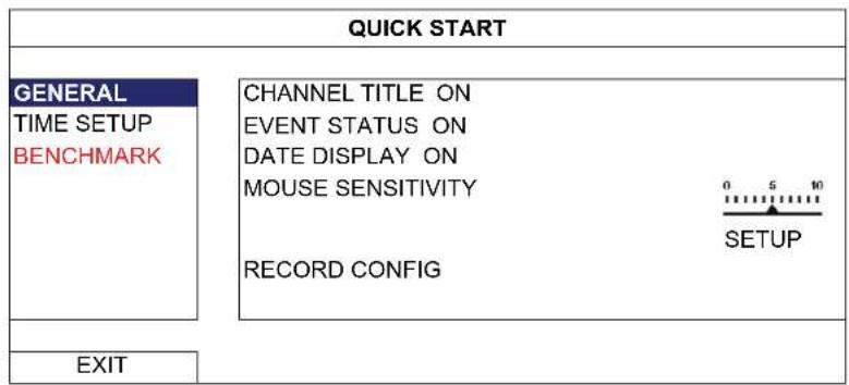
6.1.1 GENERAL
text_image
QUICK START GENERAL TIME SETUP BENCHMARK CHANNEL TITLE ON EVENT STATUS ON DATE DISPLAY ON MOUSE SENSITIVITY RECORD CONFIG 0 5 10 SETUP EXIT1) CHANNEL TITLE
Select to display the channel title or not (ON / OFF).
2) EVENT STATUS
Select to display the event icons or not (ON / OFF).
Note: For details about each event icon, please refer to "3.1 Local" at page 5.
3) DATE DISPLAY
Select to display the date or not (ON / OFF).
Select the mouse sensitivity by 9 levels.
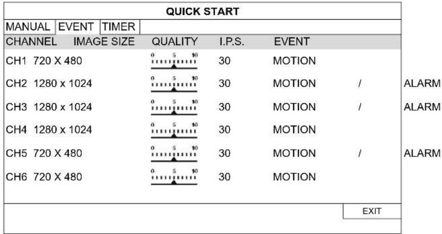
5) RECORD CONFIG
Click "SETUP" to enter the setting page individually for manual record, event record and timer record.
Note: The options selectable for "IMAGE SIZE" and "I.P.S." depends on the camera you're intended to connect.
■ MANUAL & TIMER
| QUICK START | |||||
| MANUAL | EVENT | TIMER | |||
| CHANNEL | PROFILE | TYPE | IMAGE SIZE | QUALITY | I.P.S. |
| CH1 | PROFILE-1 | H264 | 720 X 480 | 30 | |
| CH2 | PROFILE-1 | H264 | 1280 x 1024 | 30 | |
| CH3 | PROFILE-1 | H264 | 1280 x 1024 | 30 | |
| CH4 | PROFILE-1 | H264 | 1280 x 1024 | 30 | |
| CH5 | PROFILE-1 | H264 | 720 X 480 | 30 | |
| CH6 | PROFILE-1 | H264 | 720 X 480 | 30 | |
| EXIT | |||||
EVENT
text_image
QUICK START MANUAL | EVENT | TIMER | CHANNEL IMAGE SIZE QUALITY I.P.S. EVENT CH1 720 X 480 0 5 10 30 MOTION CH2 1280 x 1024 0 5 10 30 MOTION / CH3 1280 x 1024 0 5 10 30 MOTION / CH4 1280 x 1024 0 5 10 30 MOTION CH5 720 X 480 0 5 10 30 MOTION / CH6 720 X 480 0 5 10 30 MOTION ALARM ALARM ALARM EXIT6.1.2 TIME SETUP
| QUICK START | |
| GENERAL TIME SETUP BENCHMARK | DATE 2009 / NOV / 17 TIME 15 : 35 : 53 NTP SERVER Tock.stdtime.gov.tw SYNC PERIOD DAILY GMT (UTC+08:00)TAIPEI |
| EXIT | |
1) DATE
Set the current date. The default display format is YEAR – MONTH – DATE (Y-M-D).
Note: To change the date display format, please refer to "5.2.1 DATE INFO".
2) TIME
Set the current time in HOUR : MIN : SEC.
3) NTP SERVER
Click to change the default NTP server to another server they're familiar with, or keep the default NTP server.
4) SYNC PERIOD
Select to synchronize the DVR time everyday (DAILY), or turn this function off (OFF).
5) GMT
Select your time zone. There are 75 time zones for you to choose.
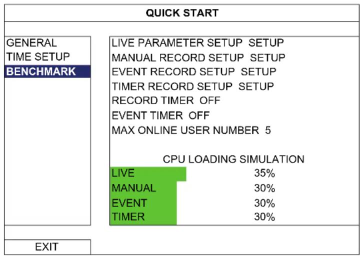
6.1.3 BENCHMARK
"BENCHMARK" is where you can see CPU loading and performance when certain functions are enabled and how the number of online users affects the performance of the device.
Note: Setting in “MAX ONLINE USER NUMBER” doesn’t really change and limit the online user number to the value you selected. This option is used for simulating the performance of the device when certain number of users are connected to this device.
other
QUICK START | Category | Status | |---|---| | GENERAL TIME SETUP BENCHMARK | LIVE PARAMETER SETUP SETUP MANUAL RECORD SETUP SETUP EVENT RECORD SETUP SETUP TIMER RECORD SETUP SETUP RECORD TIMER OFF EVENT TIMER OFF MAX ONLINE USER NUMBER 5 CPU LOADING SIMULATION LIVE 35% MANUAL 30% EVENT 30% TIMER 30% | | EXIT | |6.2 SYSTEM

6.2.1 ACCOUNT
This function is used to create a new user account, or modify or delete an existing account for different access privilege.
Note: For details about available local operations of each user level, please refer to "4.4 User Level Creation" at page 10.
flowchart
graph TD
    A["ADVANCED CONFIG"] --> B["ACCOUNT"]
    A --> C["TOOLS SYSTEM INFO BACKUP DATA (USB) BACKUP LOG (USB)"]
    A --> D["USER LIST"]
    A --> E["USER NAME LEVEL"]
    E --> F["admin SUPERVISOR"]
    E --> G["power POWER"]
    E --> H["normal NORMAL"]
    E --> I["guest GUEST"]
    J["EXIT"] --> K["ADD EDIT DEL"]
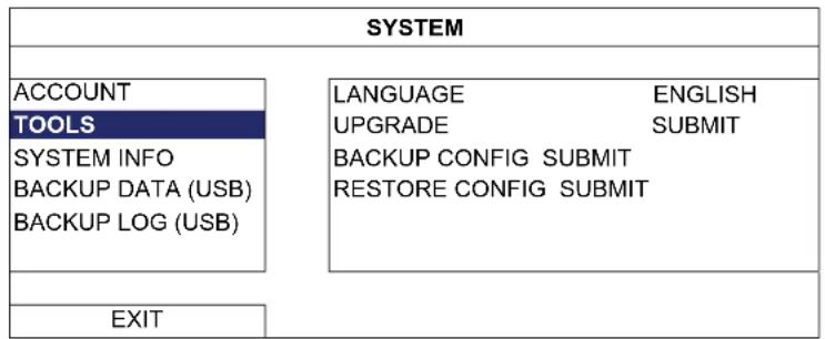
6.2.2 TOOLS
flowchart
graph TD
    A["SYSTEM"] --> B["ACCOUNT"]
    A --> C["TOOLS"]
    A --> D["SYSTEM INFO"]
    A --> E["BACKUP DATA (USB)"]
    A --> F["BACKUP LOG (USB)"]
    A --> G["LANGUAGE ENGLISH"]
    A --> H["UPGRADE SUBMIT"]
    A --> I["BACKUP CONFIG SUBMIT"]
    A --> J["RESTORE CONFIG SUBMIT"]
    K["EXIT"] --> L["EXIT"]
1) LANGUAGE
Select the language of the OSD.
2) UPGRADE
Save the upgrade files obtained from your installer or distributor in a compatible USB flash drive, and insert it into the USB port at the front panel. Then, click "SUBMIT" to start upgrading.
Note: Before using the USB flash drive, please use your PC to format the USB flash drive to FAT32 format first. For the list of compatible USB flash drives, please refer to "APPENDIX 2 COMPATIBLE USB FLASH DRIVE LIST" at page 32.
Note: After upgrading firmware, it's recommended to clear all hard disk data for the system to work more stably. Before clearing all hard disk data, please remember to make video backup.
To keep the current configurations after DVR upgrade, insert a compatible USB flash drive into the USB port, and select "SUBMIT" in "BACKUP CONFIG" to copy the current DVR configurations to a file "System.bin" and save to your USB flash drive.
To restore the DVR configurations, insert the USB flash drive including "System.bin" to the USB port, and select "SUBMIT" in "RESTORE CONFIG".
6.2.3 SYSTEM INFO
| SYSTEM | |
| ACCOUNT TOOLS | AUTO KEY LOCK NEVER CLEAR HDD HDD-0 RESET DEFAULT SUBMIT REMOTE CONTROL ID 000 |
| SYSTEM INFO BACKUP DATA (USB) BACKUP LOG (USB) | |
| EXIT | VERSION T413-T413-T413-T413 |
1) AUTO KEY LOCK
Set the time-out in second after which the key lock function is activated (NEVER / 30 / 60 / 120).
2) CLEAR HDD
Select the hard disk you want to clear, and click "YES" to confirm or "NO" to cancel.
It's recommended to clear all data in the hard disk when:
It's the first time to use this NVR to ensure the recorded data are not mixed with other data previously saved in the same hard disk.
■ The NVR firmware is upgraded for the system to work more stably. Before clearing all HDD data, please remember to make video backup.
■ NVR date and time are changed accidentally when the recording function is activated. Otherwise, the recorded data will be disordered and you will not be able to find the recorded file to backup by time search.
3) RESET DEFAULT
Click "SUBMIT" to reset all settings as default, and select "YES" to confirm or "NO" to cancel. The DVR will reboot after reset.
6.2.4 BACKUP DATA (USB)
This function is used to copy recorded video data from the NVR hard disk to a USB flash drive.
Insert a compatible USB flash drive to the USB port at the front panel, and you're able to start video backup.
| Note: Before using the USB flash drive, please use your PC to format the USB flash drive to FAT32 format first. For the list of compatible USB flash drives, please refer to “APPENDIX 2 COMPATIBLE USB FLASH DRIVE LIST” at page 32. |
| Note: | The backup video can be played on the PC. For details, please refer to “4.7 Video Playback on PC” at page 12. |
| SYSTEM | |
| ACCOUNT | START DATE 2009/NOV/19 |
| TOOLS | START TIME 08:30:21 |
| SYSTEM INFO | END DATE 2009/NOV/19 |
| BACKUP DATA (USB) | END TIME 17:59:29 |
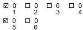
| BACKUP LOG (USB) | CHANNEL ☑ 01 ☐ 02 ☐ 03 ☐ 04 ☑ 05 ☐ 06HARD DISK ALL HDD |
| BACKUP SUBMIT | |
| REQUIRE SIZE: 554MB SUBMIT | |
| EXIT | AVAILABLE SIZE: 3788.0MB |
1) START DATE / START TIME
Select the start date & time.
2) END DATE / TIME
Select the end date & time.
3) CHANNEL
Click to select the channel(s).
4) HARD DISK
Select the hard disk containing the video data you need or "ALL HDD".
5) BACKUP
Click "SUBMIT" to start backup.
6) REQUIRE SIZE
To know the size of the expected backup video before backup, click "SUBMIT" to start calculating.
6.2.5 BACKUP LOG (USB)
This function is used to copy the event log list from the NVR to a USB flash drive.
Insert a compatible USB flash drive to the USB port at the front panel.
Note: Before using the USB flash drive, please use your PC to format the USB flash drive to FAT32 format first. For the list of compatible USB flash drives, please refer to "APPENDIX 2 COMPATIBLE USB FLASH DRIVE LIST" at page 32.
| SYSTEM | |
| ACCOUNT TOOLS SYSTEM INFO BACKUP DATA (USB) BACKUP LOG (USB) | START DATE 2009/NOV/19 START TIME 08:30:21 END DATE 2009/NOV/19 END TIME 17:59:29 CHANNEL ☑ 01 ☐ 02 ☐ 03 ☐ 04 ☑ 05 ☐ 06 DATA TYPE SETUP BACKUP SUBMIT REQUIRE SIZE: 554MB SUBMIT |
| EXIT | AVAILABLE SIZE: 3788.0MB |
1) START DATE / START TIME
Select the start date & time.
2) END DATE / TIME
Select the end date & time.
3) CHANNEL
Click to select the channel(s).
4) DATA TYPE
Click "SETUP" to select the event type you want: MANUAL / MOTION / ALARM / SYSTEM / TIMER / HUMAN DETECTION, or select "SELECT ALL" to choose all event types.
5) BACKUP
Click "SUBMIT" to start backup. You'll see a log file (.csv) in the flash drive.
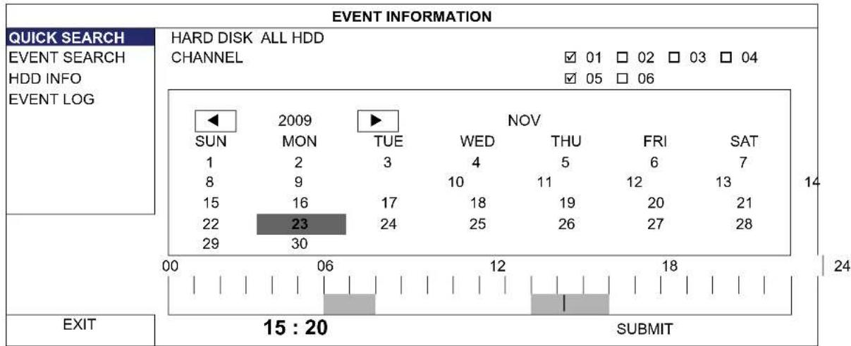
6.3.1 QUICK SEARCH
text_image
EVENT INFORMATION QUICK SEARCH EVENT SEARCH HDD INFO EVENT LOG HARD DISK ALL HDD CHANNEL ✓ 01 □ 02 □ 03 □ 04 ✓ 05 □ 06 SUN 2009 TUE NOV 1 2 3 4 5 6 7 8 9 10 11 12 13 15 16 17 18 19 20 21 22 23 24 25 26 27 28 29 30 EXIT 15 : 20 SUBMITStep1: Select the hard disk and channel including the video data you want to search.
Step2: Select the month including the video data you want to search from the calendar, and the date with recorded data will be highlighted.
Step3: Select the date you want from the calendar, and the time with recorded data will be highlighted from the time scale bar.
Step4: To immediately play the video clip, click "SUBMIT".
To choose the start time for video playback, move your mouse cursor to the highlighted time, and click to confirm the time when the time display below is the time you want. The video playback is activated right away when you confirm the time.
Note: For video playback operations, please refer to "3.1.5 Playback Panel" at page 6.
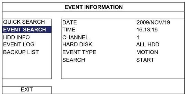
6.3.2 EVENT SEARCH
text_image
EVENT INFORMATION QUICK SEARCH EVENT SEARCH HDD INFO EVENT LOG BACKUP LIST DATE 2009/NOV/19 TIME 16:13:16 CHANNEL 1 HARD DISK ALL HDD EVENT TYPE MOTION SEARCH START EXIT1) DATE / TIME
Select the specific time period that you want to search.
2) CHANNEL
Select the video channel you want to search.
3) HARD DISK
Select the hard disk including the video data you want to search, or select "ALL HDD".
4) EVENT TYPE
Select the event type you want to search: MOTION / ALARM.
5) SEARCH
Click "START" to start search and play the video data immediately.
6.3.3 HDD INFO
You can check the information of the connected hard disk(s) in the NVR.
| EVENT INFORMATION | ||||||||
| QUICK SEARCH | NUMBER | MODEL | °C | SIZE | FREE | FORMAT TIME | SERIAL NUMBER | F.W. |
| EVENT SEARCH | HDD-0 | ST31000526SV | 46 | 890.562GB | 864.832GB | 2011/DEC/13 18:18:53 | 9V0DN5WS | ST31000526SV |
| HDD INFO | ||||||||
| EVENT LOG | ||||||||
| BACKUP LIST | ||||||||
| EXIT | ||||||||
6.3.4 EVENT LOG
You can check all the event information (event type, time and channel), or clear all log records.
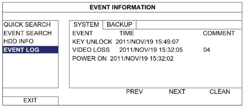
text_image
EVENT INFORMATION QUICK SEARCH EVENT SEARCH HDD INFO EVENT LOG SYSTEM BACKUP EVENT TIME COMMENT KEY UNLOCK 2011/NOV/19 15:49:07 VIDEO LOSS 2011/NOV/19 15:32:05 04 POWER ON 2011/NOV/19 15:32:02 PREV NEXT CLEAN EXIT6.4 ADVANCED CONFIG

6.4.1 CONNECTION
To assign any channel to connect to the IP camera remotely, click "URL" to enter the address of the camera, and enter its port number.
| ADVANCED CONFIG | ||||
| CONNECTION | CHANNEL | URL | PORT | CONFIG |
| CANERA | CH1 | ip_office.ddns.eagleeyes.tw | 00080 | SETUP |
| DETECTION | CH2 | 10.1.1.14 | 00088 | SETUP |
| ALERT | CH3 | 10.1.1.30 | 00088 | SETUP |
| NETWORK | CH4 | 10.1.1.12 | 00088 | SETUP |
| DISPLAY | CH5 | 10.1.1.16 | 00088 | SETUP |
| RECORD | CH6 | 10.1.1.13 | 00088 | SETUP |
| NOTIFY | ||||
| EXIT | ||||
Then, click "SETUP" to enter the access information of the camera:
| CONFIG-CH1 | |
| USERNAME admin | |
| PASSWORD |  |
| CACHE TIME (MSEC) | |
| MODEL DIGITUS | |
| GET TYPE IP CAMERA | |
| PROFILE PROFILE-3 | |
| TYPE H264 | |
| IMAGE SIZE 720 X 480 | |
| QUALITY |  |
| I.P.S. | 30 |
| AUDIO | ON |
| EXIT | |
Step1: Enter the user name and password to access the IP camera.
Step2: Click "GET TYPE" to detect and make sure the access information you're intended to connect is correct.
Step3: Select the image size, image quality, and I.P.S. Click "GET TYPE" to detect and make sure the access information you're intended to connect is correct.
Note: The options selectable for "IMAGE SIZE" and "I.P.S." depends on the camera you're intended to connect.
Step4: (Optional) For the camera with audio recording, select "ON" or "OFF".
6.4.2 CAMERA
| ADVANCED CONFIG | ||||||||||
| C O N N | E | C | T | I | O | N | CH1 | CH2 | CH3 | CH4 CH5 CH6 |
| CANERA | BRIGHTNESS | 128 | ||||||||
| DETECTION | CONTRAST | 128 | ||||||||
| ALERT | SATURATION | 128 | ||||||||
| NETWORK | HUE | 128 | ||||||||
| DISPLAY | COV. | OFF | ||||||||
| RECORD | REC | ON | ||||||||
| NOTIFY | REC AUDIO ON | |||||||||
| CHANNEL TITLE EDIT | ||||||||||
| PORT FORWARD | 81 | |||||||||
| PORT FORWARD ENABLE | ON | |||||||||
| EXIT | ||||||||||
Click the current value to manually adjust the brightness/contrast/saturation/hue of each channel here.
2) COV.
Select if you want to mask the selected channel under recording (ON / OFF). When this function is activated, the wording "COV." will be shown on the channel screen.
Note: To hide the wording "COV." When this function is on, go to "DISPLAY", and set "DISPLAY COVERT" to "OFF". For details, please refer to "6.4.6 DISPLAY" at page 27.
3) REC
Select if you want to enable recording for the selected channel (ON / OFF).
Note: When this function is disabled, no manual, event or timer recording will be activated even if any of these three record functions is set to "ON".
4) REC AUDIO
Select if you want to enable audio recording for the selected channel (ON / OFF).
Note: This function is available only when your connected device supports audio recording.
5) CHANNEL TITLE
Click "EDIT" to input the channel title (up to six characters). The default title is the channel number.
6) PORT FORWARD / PORT FORWARD ENABLE
These two functions are used when you only want to see a single channel of this NVR remotely.
a) Set the port number for the channel in "PORT FORWARD". The default value for CH1 is 81, and the default value for CH2 is 82... etc. If you want to change the port number to other value, the range is from 1 \~ 65535.
b) Select "ON" in "PORT FORWARD ENABLE".
c) The address of the channel will be "http://NVR_address:port_number". Enter the address in Internet Explorer, and see if you can access the device (IP cameras or DVR) connected channel individually.
Note: The user name and password are still required to access the device connected to the channel. Make sure you know the user name and password to access the device. For details, please refer to its user manual.
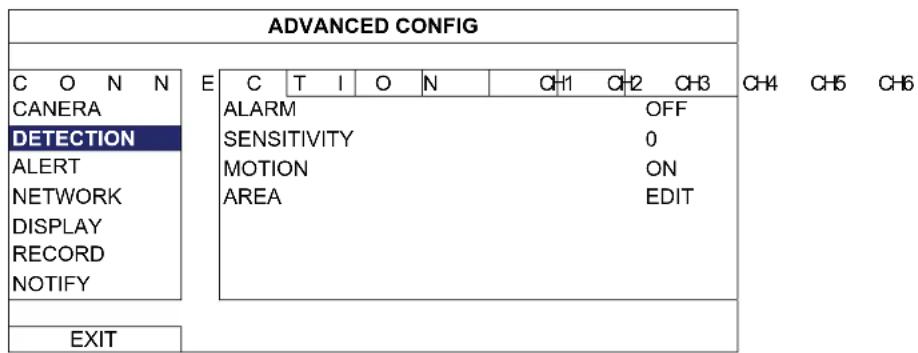
6.4.3 DETECTION
text_image
ADVANCED CONFIG C O N N CANERA DETECTION ALERT NETWORK DISPLAY RECORD NOTIFY E C T I O N CH1 CH2 CH3 ALARM OFF SENSITIVITY 0 MOTION ON AREA EDIT EXIT1) ALARM
Select N.C./ N.O depending on your installation need. The default alarm value is OFF.
2) SENSITIVITY
Select the detection sensitivity of the selected channel, the lower the value, the higher the sensitivity.
3) MOTION
Select if you want to activate the motion detection function for the selected channel (ON/OFF).
4) AREA
Click "EDIT" to set the motion detection area.
There are 16 × 12 grids per camera for all channels. Pink blocks represent the area that is not being detected while the transparent blocks are the area under detection.
Note: To exit area setting and return to the detection page, right click your mouse.
6.4.4 ALERT
Select to enable or disable the sound when any external alarm is triggered (ON / OFF).
2) INT. BUZZER
Select to enable or disable the sound (ON / OFF) for all internal buzzers: KEY BUZZER, VLOSS BUZZER, MOTION BUZZER, ALARM BUZZER, and HDD BUZZER.
Note: When this item is set to "OFF", item 3) to item 7) will be disabled even though they are set to ON.
3) KEY BUZZER
Select to enable or disable the sound when pressing the buttons on the front panel (ON / OFF).
4) VLOSS BUZZERD
Select to enable or disable the sound when video loss happened (ON / OFF).
5) MOTION BUZZER
Select to enable or disable the sound when any motion alarm is triggered (ON / OFF).
6) ALARM BUZZER
Select to enable or disable the sound when any internal alarm is triggered (ON / OFF).
7) HDD BUZZER
Select to enable or disable the sound (ON / OFF) when the HDD remaining capacity reaches to the value set in "HDD NEARLY FULL (GB)".
8) ALARM DURATION (SEC)
Select the duration time for alarm buzzer in second (5 / 10 / 20 / 40).
9) HDD NEARLY FULL (GB)
If HDD BUZZER is enabled, select the duration time for buzzer notifications when the hard disk available capacity is 5/10/15/20 GB left.
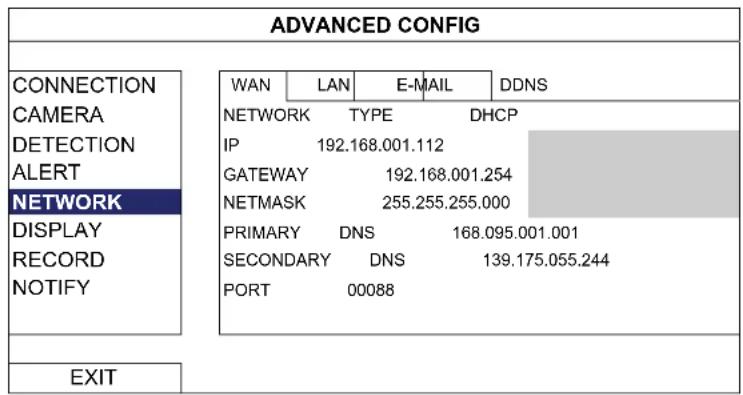
6.4.5 NETWORK
There are two RJ45 ports on the DVR rear panel: WAN and LAN.
■ WAN is used to connect this NVR to Internet for remote access from anywhere as long as Internet access is available.
■ LAN is used to connect to IP cameras locally.
text_image
ADVANCED CONFIG CONNECTION CAMERA DETECTION ALERT NETWORK DISPLAY RECORD NOTIFY WAN LAN E-MAIL DDNS NETWORK TYPE DHCP IP 192.168.001.112 GATEWAY 192.168.001.254 NETMASK 255.255.255.000 PRIMARY DNS 168.095.001.001 SECONDARY DNS 139.175.055.244 PORT 00088 EXIT6.4.6 DISPLAY
| ADVANCED CONFIG | ||
| CONNECTION CANERA DETECTION ALERT NETWORK DISPLAY RECORD NOTIFY | FULL SCREEN DURATION DISPLAY COVERT HDD DISPLAY MODE BRIGHTNESS CONTRAST SATURATION | 03 ON SIZE 128 128 128 |
| EXIT | ||
Select the full screen dwell duration time in second (03 / 05 / 10 / 15).
2) DISPLAY COVERT
Select "ON" or "OFF" to display or hide the wording "COV." When covert recording is activated in "CAMERA".
3) HDD DISPLAY MODE
Select "SIZE" to show the remaining hard disk capacity for recording in GB, or "TIME" to show the remaining recording time.
Click the current value to manually adjust the brightness/contrast/saturation/ of the screen.
6.4.7 RECORD
Note: Please DO NOT change the date or time of your NVR after the recording function is activated. Otherwise, the recorded data will be disordered and you will not be able to find the recorded file to backup by time search. If users change the date or time accidentally when the recording function is activated, it's recommended to clear all hard disk data, and start recording again.
| ADVANCED CONFIG | |
| CONNECTION CANERA DETECTION ALERT NETWORK DISPLAY RECORD NOTIFY | MANUAL RECORD OFF EVENT RECORD ON TIMER RECORD OFF PRE-ALARM RECORD ON OVERWRITE ON KEEP DATA LIMIT (DAYS) OFF RECORD CONFIG SETUP |
| EXIT | |
1) MANUAL RECORD
Set the manual recording function on / off.
2) EVENT RECORD
Set the event recording function on / off.
3) TIMER RECORD
Set the timer recording function on / off.
4) PRE-ALARM RECORD
Select to enable or disable the pre-alarm function (ON / OFF).
When pre-alarm and event recording functions are both activated, the DVR will record 8MB data before an alarm / motion event is triggered.
5) OVERWRITE
Select "ON" to overwrite previous recorded data in your HDD when the HDD is full. When this function is on and the HDD is full, the DVR will clear 8GB data from the oldest for continuous recording without notice.
6) KEEP DATA LIMITS (DAYS)
Assign the maximum recording days from 01 to 31 after which all the recorded data will be removed, or select "OFF" to disable this function.
7) RECORD CONFIG
Click "SETUP" to enter the setting page individually for manual record, event record and timer record. For details, please refer to "6.1.1 GENERAL" at page 16.
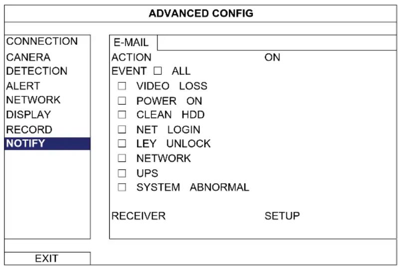
6.4.8 NOTIFY
You can send notifications for certain events to the E-mail address(es) specified.
Note: Make sure you have configured an E-mail account in "NETWORK" → "E-MAIL" to send the notifications.
Enable this function in "ACTION", select the event type(s) you want to send notifications in "EVENT", and add the E-mail address(es) to which you want to send notifications in "RECEIVER".
text_image
ADVANCED CONFIG CONNECTION CANERA DETECTION ALERT NETWORK DISPLAY RECORD NOTIFY E-MAIL ACTION ON EVENT □ ALL □ VIDEO LOSS □ POWER ON □ CLEAN HDD □ NET LOGIN □ LEY UNLOCK □ NETWORK □ UPS □ SYSTEM ABNORMAL RECEIVER SETUP EXIT6.5 SCHEDULE SETTING

6.5.1 RECORD
Select "ON" to enable record timer, and select the day and time for this function.
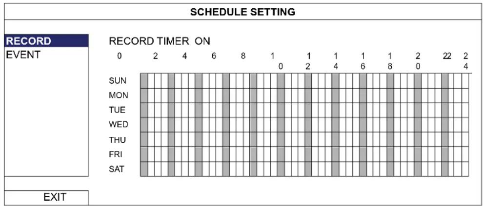
X axis: 0 \~ 24 hours. Each time bar is 30 minutes.
Y axis: Monday \~ Sunday.
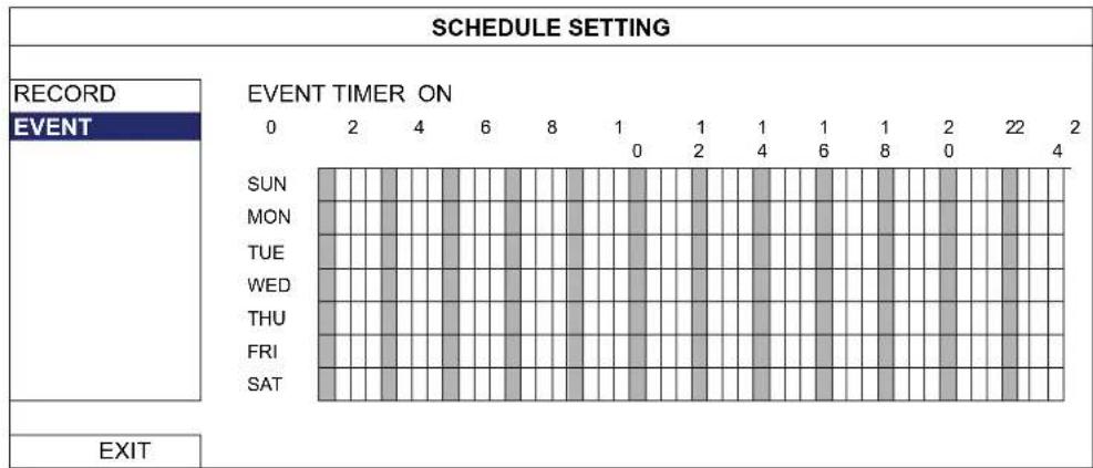
6.5.2 EVENT
Select "ON" to enable event timer, and select the day and time for this function.
bar
SCHEDULE SETTING | Event | 0 | 2 | 4 | 6 | 8 | 1 | 1 | 1 | 1 | 8 | 2 | 22 | 2 | |---|---|---|---|---|---|---|---|---|---|---|---|---|---| | SUN | 0 | 0 | 0 | 0 | 0 | 0 | 0 | 0 | 0 | 0 | 0 | 0 | 0 | | MON | 0 | 0 | 0 | 0 | 0 | 0 | 0 | 0 | 0 | 0 | 0 | 0 | 0 | | TUE | 0 | 0 | 0 | 0 | 0 | 0 | 0 | 0 | 0 | 0 | 0 | 0 | 0 | | WED | 0 | 0 | 0 | 0 | 0 | 0 | 0 | 0 | 0 | 0 | 0 | 0 | 0 | | THU | 0 | 0 | 0 | 0 | 0 | 0 | 0 | 0 | 0 | 0 | 0 | 0 | 0 | | FRI | 0 | 0 | 0 | 0 | 0 | 0 | 0 | 0 | 0 | 0 | 0 | 0 | 0 | | SAT | 0 | 0 | 0 | 0 | 0 | 0 | 0 | 0 | 0 | 0 | 0 | 0 | 0 | EXITX axis: 0 \~ 24 hours. Each time bar is 30 minutes.
Y axis: Monday \~ Sunday.
APPENDIX 1 MOBILE SURVEILLANCE VIA EAGLEEYES
EagleEyes is a mobile phone program used with our surveillance system for remote surveillance. It has several advantages:
■ It's free (Except EagleEyes Plus for iPhone).
It's compatible with several popular mobile platforms, such as iPhone, iPad and Android.
It's easy to download, install and configure. For more details about configuring and operating this program, please visit our official website www.eagleeyescctv.com.
A2.1 Prerequisites
Before installing EagleEyes to your mobile phone for remote surveillance, make sure you have checked the following:
√ Your mobile platform is iPhone, iPad & Android.
√ Mobile Internet services are subscribed and available to use for your mobile phone.
Note: You might be charged for Internet access via wireless or 3G networks. For the Internet access rate details, please check with your local network operator or service provider.
√ You have noted down the IP address, port number, user name and password used to access your network camera from Internet.
A2.2 Where to download
Connect to www.eagleeyescctv.com from your mobile phone, and sign in.
Note: Please DO NOT try to download EagleEyes from your computer.
Then, select "Software" and the mobile platform of your phone to download EagleEyes to your phone.
■ For Android & iPad, select the download link from the website to start downloading.
■ For iPhone, two versions of EagleEyes are available:
-- EagleEyes Plus (US\$4.99), and
-- EagleEyes Lite (Free).
Select the version you want, and you'll be directed to "App Store" to download the application.
Note: You can also find EagleEyes on "App Store" from your iPhone. Go to "App Store", and select "Search". Enter the keyword "eagleeyes" to find and download the version you want.

text_image
iPhone BlackBerry Symbian Win Mobile More... Software >> iPhone Download iPhone EagleEyes Lite (Free) Download iPhone EagleEyes Plus (US$4.99) EagleEyes for iPhone unleashes the power of mobile surveillance within your iPhone. Working hand in hand with AVTECH IVS range units, iPhone pushes notifications to you even when you are on the road and allows you to instantaneously logging back in your DVR to check in on your treasured property. If you have controllable cameras on site like zoom or PTZ cameras, EagleEyes for iPhone provides you the most intuitive and convenient control right at your finger tips. EagleEyes for iPhone is the best compliment to your powerful AVTECH surveillance system.When the download is completed, EagleEyes will be installed automatically to the location where all applications are saved in your phone by default, or where you specify.
Note: For more details about configuring and operating this program, please visit our official website www.eagleeyescctv.com.
APPENDIX 2 COMPATIBLE USB FLASH DRIVE LIST
Please upgrade the firmware of the NVR to the latest version to ensure the accuracy of the following table. If the USB flash drive is not supported by the NVR, the "USB ERROR" message will be shown on the screen.
Note: Please use your PC to format the USB flash drive as "FAT32".
Note: You can backup up to 2GB video data for one-time USB backup. To backup more data, please set the time & channel(s) you want, and start USB backup again.
| MANUFACTURER MODEL CAPACITY | ||
| Transcend | JFV35 | 4G |
| JFV30 | ||
| Kingston | DataTraveler | 1G |
| PQI | U172P | 4G |
| Apacer | AH320 | 2GB |
| AH320A | ||
| AH220 | ||
| AH320 | ||
| A-data | RB-18 | 1GB |
| Sandisk | Cruzer Micro | |
| Cruzer Micro | 4G | |
| Cruzer4-pk | 2G | |
| Netac | U208 | 1G |
| MSI | F200 | 4G |
| SONY Micro Vault Tiny 2G | 2G | |
| Micro Vault Tiny 4G | 4G | |
| Micro Vault Tiny | 1G | |
APPENDIX 3 COMPATIBLE HARD DISK LIST
Please upgrade the firmware of the device to the latest version to ensure the accuracy of the following table.
| MANUFACTURER MODEL CAPACITY ROTATION | |||
| Seagate | ST3320613AS | 320GB | 7200 |
| ST33500320AS | 500GB | 7200 | |
| ST3500410SV | 500GB | 7200 | |
| ST3750330AS | 750GB | 7200 | |
| ST31000525SV | 1000GB | 7200 | |
| ST31000340AS | 1000GB | 7200 | |
| WD | WD3200AAKS | 320GB | 7200 rpm |
| WD5000AACS | 500GB | 7200 rpm | |
| WD6400AAKS | 640GB | 7200 rpm | |
| WD7500AAKS | 750GB | 7200 rpm | |
| WD10EADS | 1TB | 7200 rpm | |
| WD15EADS | 1.5TB | 7200 rpm | |
| WD20EADS | 2TB | 7200 rpm | |
| Maxtor | STM3500320AS | 500GB | 7200 rpm |
| STM3750330AS | 750GB | 7200 | |
| HITACHI | HDT725032VLA360 | 320GB | 7200 rpm |
| HDS721010KLA330 | 1000GB | 7200 rpm | |
| rpm | |
| rpm | |
| rpm | |
| rpm | |
| rpm | |
| rpm | |
| rpm |
APPENDIX 4 BATTERY REPLACEMENT
The time reset after power failure, for example, caused by a power outage, will cause the disorder of the recorded data, and users may have problems in searching the event clip they want. To keep the device time from resetting, a non-chargeable lithium battery, CR2032, is installed in the device.
However, the device time might still get reset when the battery is low or even running out of power. If so, please replace the device battery, CR2032, right away as instructed below.
How to replace CR2032
Note: The lithium battery, CR2032, is a non-chargeable battery, and should be purchased separately. Please replace only with the same or equivalent type battery in case of danger.
Step1: Stop all recording immediately to prevent the disorder of the recorded data. Then, back up the recorded data if necessary.
Step2: Power off the device, and disconnect the power.
Step3: Remove the device cover, and find the battery on the mainboard.
Step4: Push the release as indicated below to remove the battery.

Type1

Type 2
Step5: Get a new battery and install it to its slot on the mainboard.
■ For Type 1, install it with the side of "CR2032" facing up as shown above.
■ For Type 2, install it without the side of "CR2032" facing you as shown above.
Step6: Replace the cover and connect to power.
Step7: Set the date & time, and resume recording.
| Hardware | ||
| Video Input | One LAN portUp to 6 Channels with a 6-port hub | |
| Video Output HDMI | ||
| Video Output Resolution 1920 x 1080 | ||
| Audio Input YES | ||
| Audio Output YES (Line Out / HDMI) | ||
| HDD Storage** Up to two 3TB HDDs | ||
| USB Ports | Two on the front panel:one for video backup to USB flash drive, andanother for NVR control via a USB mouse | |
| IR Remote Control YES | ||
| Ethernet | LAN port | 1000Mbps |
| Internet port 10Mbps / 100Mbps | ||
| Software | ||
| Video Compression Format H.264 / MPEG4 / MJ | JPEG | |
| Recording Mode Manual / Event / Alarm / Schedule | ||
| Recording Throughput 50Hz | IP camera Up to 150 @ 720P, 32 Mbps | |
| 60Hz IP camera Up to 180 | @ 720P, 32 Mbps | |
| Pre-alarm Recording YES | ||
| Quick Search Time / Motion / Alarm | ||
| Security Multiple user access levels with password | ||
| Remote Access | (1) Internet Explorer on Windows operating system(2) EagleEyes on iPhone, iPad & Android mobile devices(3) Our self-developed program, Video Viewer | |
| General | ||
| Power Source (±10%) | DC 19V / 2.1A | |
| Operating Temperature | 10°C ~ 40°C (50°F~104°F) | |
| Dimensions (mm)** | 375(W) × 55(H) × 264(D) | |
| Minimum PC Browsing Requirements | · Pentium 4 CPU 1.3 GHz or higher, or equivalent AMD· 256 MB RAM· AGP graphics card, Direct Draw, 32MB RAM· Windows 7, Vista & XP, DirectX 9.0 or later· Internet Explorer 7.x or later | |
| Peripherals | (1) EoC converter(2) High Resolution Display Extender(3) Video Server | |
* Specifications are subject to change without notice.
** Dimensional tolerance: ±5mm