
ANT800R - TV Antenna AUDIOVOX - Free user manual and instructions
Find the device manual for free ANT800R AUDIOVOX in PDF.

| Product Type | Indoor/Outdoor HDTV Antenna |
| Brand | Audiovox |
| Model | ANT800R |
| Frequency Range | VHF (174-230 MHz), UHF (470-700 MHz) |
| Amplification | Built-in amplifier with 5V DC power |
| Gain | Up to 35 dB |
| Range | Up to 60 miles |
| Dimensions | 14.5 x 9.5 x 2.5 inches |
| Weight | 1.2 lbs |
| Cable Length | 20 feet coaxial cable with F-type connectors |
| Power Supply | USB power adapter (5V, 500mA) included |
| Mounting Options | Tabletop stand, wall mount bracket, and mast clamp |
| Weather Resistance | Weatherproof for outdoor use |
| Signal Booster | Automatic gain control and amplifier switch |
| Connectivity | Single coaxial output |
| Color | Black |
| Cleaning Instructions | Wipe with a soft, dry cloth. Do not use liquids or abrasives. |
| Safety Notes | Do not install near power lines; disconnect during lightning storms. |
| Repairability | No user-serviceable parts; contact Audiovox support for repairs. |
Frequently Asked Questions - ANT800R AUDIOVOX
User questions about ANT800R AUDIOVOX
0 question about this device. Answer the ones you know or ask your own.
Ask a new question about this device
Download the instructions for your TV Antenna in PDF format for free! Find your manual ANT800R - AUDIOVOX and take your electronic device back in hand. On this page are published all the documents necessary for the use of your device. ANT800R by AUDIOVOX.
USER MANUAL ANT800R AUDIOVOX
natural_image
Exterior view of a dark square electronic device with a flat top surface (no text or symbols visible)RCA
ANT800
Outdoor Antenna
User's Guide
BEFORE YOU START!!!
Please read the IMPORTANT SAFETY INFORMATION sheet included in this package.
Getting Started
Remove the antenna and the hardware bag from package. Make sure the following parts are in the package:
- Antenna
- Amplifier Insert
- Power Adapter
- Mounting Base
- Mounting Arm
- Hardware bag:
(2) Screws (4) Screw Covers
(2) U-Bolts (2) Clamps
(4) Wing Nuts (4) Wood Screws
(1) Rubber Boot for Antenna Connector/Coaxial Cable
Finding the Right Location
Before you mount the ANT800, consider the following factors in reception performance:
• The ANT800 usually performs best when mounted horizontally
- The ANT800 should be mounted on the side of your house that faces most of your local broadcast towers (See illustration below) Visit www.antennaweb.org to see the locations of your local broadcast towers.
- The higher the elevation of the antenna, the better the reception performance will be.
Mounting the Antenna
The ANT800 mounting bracket gives you flexibility in mounting the antenna.
The ANT800 can be mounted:
- To a surface, such as a rooftop, eaves, siding, or rafters in an attic
— OR —
• To a standard mast (not included)
WARNING: Never hang anything from the ANT800; never attach foreign objects to the ANT800.
NOTES: Do not install the ANT800 on any metal surface, including aluminum siding. Mounting on a metal surface will seriously degrade reception quality.
In most cases, the ANT800 provides the best performance when mounted outdoors in a high location (such as on the roof or high up on the side of your house). The ANT800 can also be mounted in an attic.
Mounting to a Surface
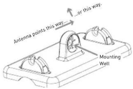
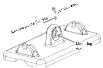
1. Orient the antenna base.
Make sure the base is oriented correctly for the direction you want to point the antenna. Use the illustration on the left as a guide.
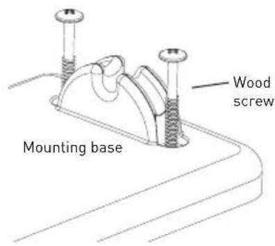
2. Mount the base to the surface.
Find the four wood screws included in this package. Using these screws, attach the base to the surface as shown here.
natural_image
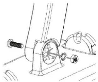
Technical line drawing of a mechanical assembly with gears and shafts (no text or symbols)3. Attach the arm to the base.
Find one of the screws, washers, and nuts included in the package.
First, set the washer and nut in the mounting well. Then position the arm over the other side of the well. Attach the arm to the base as shown here.
natural_image
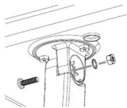
Technical line drawing of a mechanical assembly with no visible text or symbols4. Attach the antenna to the arm.
Find the other screw, washer, and nut.
First, set the washer and nut in the antenna's mounting well. Then position the arm over the other side of the well. Attach the arm to the antenna as shown here.
continues on next page...
natural_image
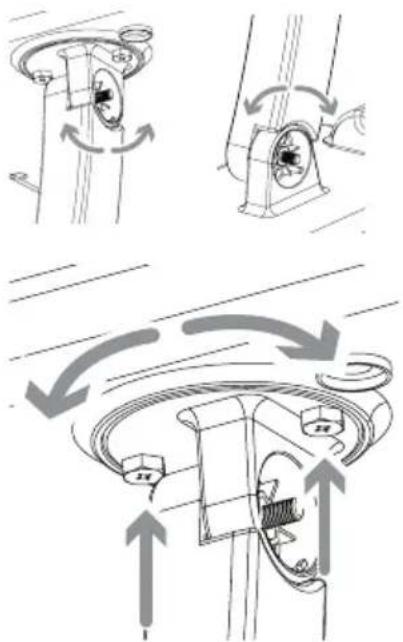
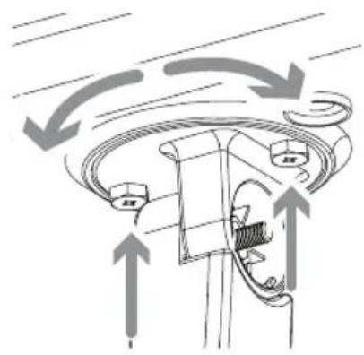
Technical diagram showing mechanical assembly with rotating components and directional arrows (no text or symbols)5. Position and orient the antenna.
Loosen the screws between the arm and the base or antenna just enough so that you can position and orient the antenna the way you want.
You can also adjust the antenna's orientation on the antenna itself. On the antenna's underside, next to the arm, there are two screws. Loosen these just enough so that you can rotate the antenna on the arm. Once you've found the orientation you want, tighten these screws.
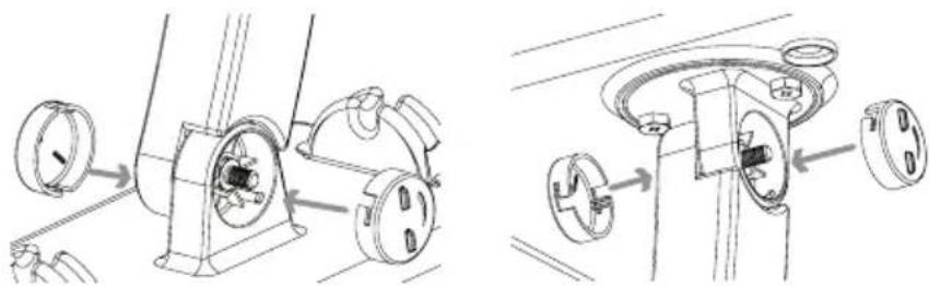
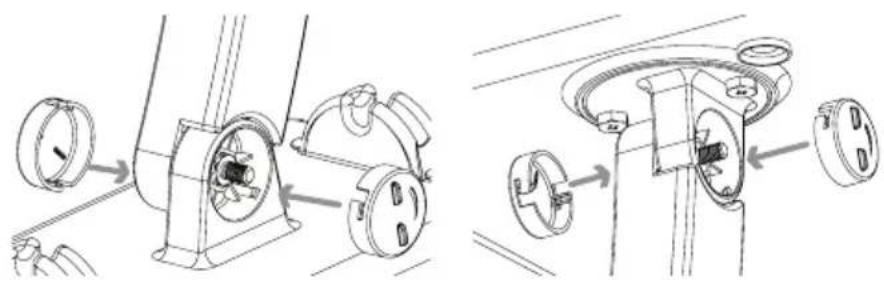
6. Tighten all screws. Attach the screw covers.
natural_image
Technical line drawing showing two mechanical assembly steps with no visible text or symbols7. Skip to the "Connecting to Your TV" section to complete installation.
Mounting to a Mast
1. Orient the antenna base.
Make sure the base is oriented correctly for the direction you want to point the antenna. Use the illustration on the left as a guide.
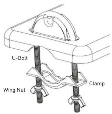
2. Attach the clamp assemblies to the base.
Find the two U-Bolts, the four wing nuts, and the two clamps included in this package.
Insert each U-Bolt into the base as shown here. Then position a clamp and two wing nuts on the end of each of U-Bolt as shown here.
natural_image
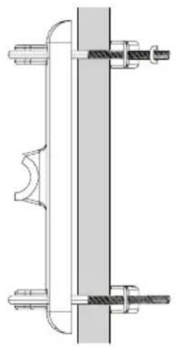
Technical line drawing of a mechanical assembly with two vertical components and threaded fasteners (no text or symbols)3. Mount the base to the mast (not included).
Slide the antenna clamp assembly over the mast as shown here, positioning the mast between the clamp and the antenna.
Position the ANT800 antenna as high as possible on the mast. Orient the base in the direction you want. Then tighten the clamps and wing nuts securely onto the mast.
natural_image
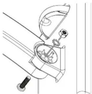
Technical line drawing of a mechanical device with gears and lever (no text or symbols)4. Attach the arm to the base.
Find one of the screws, washers, and nuts included in the package.
First, set the washer and nut in the mounting well. Then position the arm over the other side of the well. Attach the arm to the base as shown here.
continues on next page...
natural_image
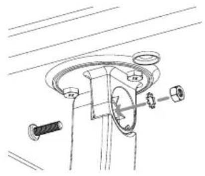
Technical line drawing of a mechanical assembly with bolts and a central component (no text or symbols)5. Attach the antenna to the arm.
Find the other screw, washer, and nut.
First, set the washer and nut in the antenna's mounting well. Then position the arm over the other side of the well. Attach the arm to the antenna as shown here.
natural_image
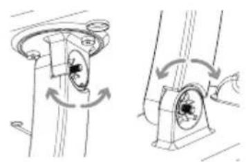
Mechanical assembly diagram showing two configurations of rotating components with arrows indicating rotation direction (no text or labels)6. Position and orient the antenna.
Loosen the screws between the arm and the base or antenna just enough so that you can position and orient the antenna the way you want.
natural_image
Diagram of a mechanical component with directional arrows indicating motion or flow (no text or symbols)You can also adjust the antenna's orientation on the antenna itself. On the antenna's underside, next to the arm, there are two screws. Loosen these just enough so that you can rotate the antenna on the arm. Once you've found the orientation you want, tighten these screws.
7. Tighten all screws. Attach the screw covers.
natural_image
Technical line drawing showing two mechanical assembly steps with labeled components (no text or symbols)8. Skip to the "Connecting to Your TV" section to complete installation.
Connecting to Your TV
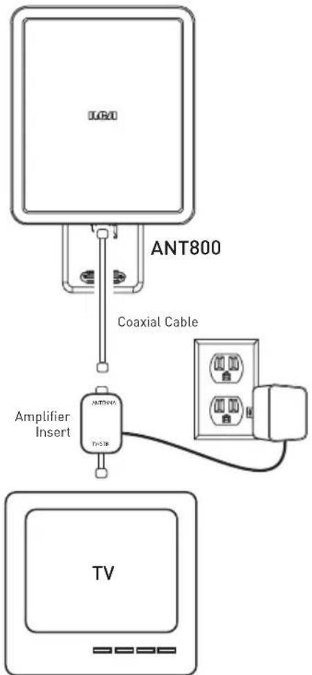
- Run an RG6 coaxial cable from the antenna towards your television set. Connect the RG6 coaxial cable to the ANT jack on the supplied amplifier insert.
- Connect built-in coaxial cable on the amplifier insert to the antenna input jack on your TV or converter box.
Note: If you want to split the signal coming from the antenna, connect the short coaxial cable built into the amplifier insert to your splitter (splitter sold separately). DO NOT PUT THE SIGNAL SPLITTER BETWEEN THE AMPLIFIER INSERT AND THE ANTENNA.
- After all other connections are made, connect the power adapter into the amplifier insert. Plug it into a standard AC outlet.
Important: This power adapter should be plugged in so that it stays vertical or lays flat.
The amplifier insert should always be located indoors.
Water Damage Prevention:
At the point where your coaxial cable lead enters the house, you should allow for some slack in the coaxial cable as a "drip loop." This will prevent moisture from running down the coaxial cable and entering the house.
Run the coaxial cable approximately six inches below the wall entry point and then turn it upwards towards this spot. Any moisture that accumulates on the coaxial cable will drip off in the bend instead of running into the house. You should seal the point where the cable enters your home with a rubber weather insulator or silicone caulking (not included). An “F” connector wall plate can be used inside the home to cover the inside portion of the hole. You can typically find an “F” connector wall plate at any local electronics or hardware store.
12 Month Limited Warranty
Audiovox Electronics Corporation (the "Company") warrants to the original retail purchaser of this product that should this product or any part thereof, under normal use and conditions, be proven defective in material or workmanship within 12 months from the date of original purchase, such defect(s) will be repaired or replaced (at the Company's option) without charge for parts and repair labor. To obtain repair or replacement within the terms of this Warranty, the product along with any accessories included in the original packaging is to be delivered with proof of warranty coverage (e.g. dated bill of sale), specification of defect(s), transportation prepaid, to the Company at the address shown below. Do not return this product to the Retailer.
This Warranty is not transferable and does not cover product purchased, serviced or used outside the United States or Canada. The warranty does not extend to the elimination of externally generated static or noise. This Warranty does not apply to costs incurred for installation, removal or reinstallation of the product, or, if in the Company's opinion, the product has been damaged through acts of nature, alteration, improper installation, mishandling, misuse, neglect, or accident. This warranty does not cover damage caused by an AC adapter not provided with the product.
THE EXTENT OF THE COMPANY'S LIABILITY UNDER THIS WARRANTY IS LIMITED TO THE REPAIR OR REPLACEMENT PROVIDED ABOVE AND, IN NO EVENT, SHALL THE COMPANY'S LIABILITY EXCEED THE PURCHASE PRICE PAID BY PURCHASER FOR THE PRODUCT. This Warranty is in lieu of all other express warranties or liabilities. ANY IMPLIED WARRANTIES, INCLUDING ANY IMPLIED WARRANTY OF MERCHANTABILITY OR FITNESS FOR A PARTICULAR PURPOSE, SHALL BE LIMITED TO DURATION OF THIS WARRANTY. ANY ACTION FOR BREACH OF ANY WARRANTY HEREUNDER, INCLUDING ANY IMPLIED WARRANTY, MUST BE BROUGHT WITHIN A PERIOD OF 24 MONTHS FROM THE DATE OF ORIGINAL PURCHASE. IN NO CASE SHALL THE COMPANY BE LIABLE FOR ANY CONSEQUENTIAL OR INCIDENTAL DAMAGES WHATSOEVER. No person or representative is authorized to assume for the Company any liability other than expressed herein in connection with the sale of this product.
Some states/provinces do not allow limitations on how long an implied warranty lasts or the exclusion or limitation of incidental or consequential damage so the above limitations or exclusions may not apply to you. This Warranty gives you specific legal rights and you may also have other rights which vary from state/province to state/province.
U.S.A.: Audiovox Electronics Corporation, 150 Marcus Blvd., Hauppauge, NY 11788
CANADA: Audiovox Return Center, c/o Genco, 6685 Kennedy Road, Unit #3 Door 16, Mississauga Ontario L5T 3A5
natural_image
Exterior view of a black square electronic device with a flat top (no text or symbols visible)RCA
ANT800
Antena Exterior
Guía del Usuario
iiiiANTES DE COMENZAR!!!
natural_image
Technical line drawing of a mechanical assembly with gears and shafts (no text or symbols)3. Fije el brazo en la base.
natural_image
Technical line drawing of a mechanical assembly with no visible text or symbolsnatural_image
Technical line drawing showing two mechanical assembly steps with rotating components (no text or symbols)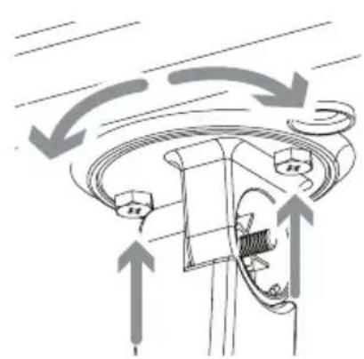
natural_image
Diagram of a mechanical or electrical component with directional arrows indicating motion or flow (no text or symbols present)5. Coloque y oriente la antena.
natural_image
Technical line drawing of a mechanical assembly with two views showing internal components (no text or symbols)natural_image
Technical line drawing of a mechanical assembly with threaded fasteners and a central shaft (no text or symbols)natural_image
Technical line drawing of a mechanical device with no visible text or symbolsnatural_image
Technical line drawing of a mechanical assembly with no visible text or symbols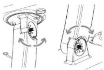
natural_image
Technical line drawing of a mechanical assembly with rotating components (no text or symbols)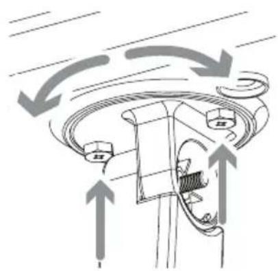
natural_image
Diagram of a mechanical component with directional arrows indicating motion or flow (no text or symbols)natural_image
Technical line drawing showing two mechanical assembly steps with circular components and mounting brackets (no text or symbols)U.S.A.: Audiovox Electronics Corporation, 150 Marcus Blvd., Hauppauge, NY 11788 CANADÁ: Audiovox Return Center, c/o Genco, 6685 Kennedy Road, Unit #3 Door 16, Mississauga Ontario L5T 3A5

- RCA
- ANT800
- Outdoor Antenna
- User's Guide
- BEFORE YOU START!!!
- Getting Started
- Finding the Right Location
- Mounting the Antenna
- Mounting to a Surface
- Orient the antenna base.
- Mount the base to the surface.
- Attach the arm to the base.
- Attach the antenna to the arm.
- Position and orient the antenna.
- Tighten all screws. Attach the screw covers.
- Skip to the "Connecting to Your TV" section to complete installation.
- Mounting to a Mast
- Attach the clamp assemblies to the base.
- Mount the base to the mast (not included).
- Attach the arm to the base.
- Attach the antenna to the arm.
- Position and orient the antenna.
- Tighten all screws. Attach the screw covers.
- Skip to the "Connecting to Your TV" section to complete installation.
- Connecting to Your TV
- Water Damage Prevention:
- Month Limited Warranty
- Antena Exterior
- Guía del Usuario
- iiiiANTES DE COMENZAR!!!
- Fije el brazo en la base.
- Coloque y oriente la antena.
Brand : AUDIOVOX
Model : ANT800R
Category : TV Antenna