DA-681-I-DPP-T-CE - Network switch Moxa - Free user manual and instructions
Find the device manual for free DA-681-I-DPP-T-CE Moxa in PDF.

User questions about DA-681-I-DPP-T-CE Moxa
0 question about this device. Answer the ones you know or ask your own.
Ask a new question about this device
Download the instructions for your Network switch in PDF format for free! Find your manual DA-681-I-DPP-T-CE - Moxa and take your electronic device back in hand. On this page are published all the documents necessary for the use of your device. DA-681-I-DPP-T-CE by Moxa.
USER MANUAL DA-681-I-DPP-T-CE Moxa
DA-681 Series Embedded Computer Hardware User's Manual
Fifth Edition, January 2010
www.moxa.com/product
MOXA®
© 2010 Moxa Inc. All rights reserved. Reproduction without permission is prohibited.
DA-681 Series Embedded Computer Hardware User's Manual
Any software described in this manual is furnished under a license agreement and may be used only in accordance with the terms of that agreement.
Copyright Notice
Copyright © 2010 Moxa Inc.
All rights reserved.
Reproduction without permission is prohibited.
Trademarks
MOXA is a registered trademark of Moxa Inc.
All other trademarks or registered marks in this manual belong to their respective manufacturers.
Disclaimer
Information in this document is subject to change without notice and does not represent a commitment on the part of Moxa.
Moxa provides this document “as is,” without warranty of any kind, either expressed or implied, including, but not limited to, its particular purpose. Moxa reserves the right to make improvements and/or changes to this manual, or to the products and/or the programs described in this manual, at any time.
Information provided in this manual is intended to be accurate and reliable. However, Moxa assumes no responsibility for its use, or for any infringements on the rights of third parties that may result from its use.
This product might include unintentional technical or typographical errors. Changes are periodically made to the information herein to correct such errors, and these changes are incorporated into new editions of the publication.
Technical Support Contact Information
www.moxa.com/support
Moxa Americas:
Toll-free: 1-888-669-2872
Tel: +1-714-528-6777
Fax: +1-714-528-6778
Moxa China (Shanghai office):
Toll-free: 800-820-5036
Tel: +86-21-5258-9955
Fax: +86-10-6872-3958
Moxa Europe:
Tel: +49-89-3 70 03 99-0
Fax: +49-89-3 70 03 99-99
Moxa Asia-Pacific:
Chapter 1 Introduction....1-1
Overview....1-2
Model Descriptions and Package Checklist.... 1-2
Appearance 1-3
Dimensions 1-4
Features....1-4
Hardware Block Diagram....1-5
DA-681 Basic System 1-5
Hardware Specifications 1-6
Non-standard Baudrates....1-8
Chapter 2 Hardware Installation....2-1
Placement Options 2-2
Desktop....2-2
Rack mounting 2-2
Wiring Requirements 2-4
Connecting the Power 2-5
Wiring the Power Inputs 2-6
Power Input Wiring Description 2-9
HIPOT (Dielectric Strength) Testing 2-11
Reset Button....2-12
Front Panel LED 2-12
Connecting to a Display.... 2-13
Connecting a PS/2 Keyboard and Mouse.... 2-13
Connecting USB Devices 2-14
LAN Ports 2-14
Upgrading the Memory Module 2-16
Installing a CompactFlash Card.... 2-18
Installing a SATA Hard Disk.... 2-19
Chapter 3 BIOS Setup ....3-1
Entering the BIOS Setup Utility 3-2
Modifying the BIOS Main Settings 3-3
Basic Configuration.... 3-3
System Security.... 3-3
Advanced Settings 3-4
Hard Disk Boot Priority.... 3-4
Advanced BIOS Features 3-5
CPU Features.... 3-5
Advanced Chipset Settings.... 3-7
PnP/PCI Configurations 3-8
Frequency/Voltage Control 3-9
Peripherals 3-9
OnChip IDE Device 3-10
Onboard Device.... 3-11
Onboard I/O Chip Setup 3-12
Power 3-13
Wake Up Control....3-13
Hardware Monitor.... 3-14
Load Defaults.... 3-15
Exiting the BIOS Setup.... 3-16
Upgrading the BIOS 3-17
Appendix A Safety Installation Instructions....A-1
Appendix B Regulatory Statement Approval ...... B-1
Thank you for purchasing the Moxa DA-681 series x86-based industrial ready-to-run embedded computer.
This manual introduces the hardware installation, connector interfaces and BIOS setup of the DA-681. For software configuration and management, please refer to the user's manual for your operating system.
This chapter covers the following topics:
Overview
☐ Model Descriptions and Package Checklist
□ Appearance
Dimensions
Features
□ Hardware Block Diagram
➢ DA-681 Basic System
Hardware Specifications
□ Non-standard Baudrates
Overview
The DA-681 computer is based on the Intel x86 processor and supports VGA, 6 Ethernet ports, 4 RS-232 and 8 RS-485 serial ports with optical isolation, CompactFlash, and USB. The DA-681 comes in a standard 19-inch, 1U high form factor, making it an ideal platform for industrial applications.
With its robust design, the DA-681 is suitable for industrial automation applications that require standard 19-inch rackmount solutions, such as power automation, transportation, and oil and gas. Another plus is that the serial ports come with 2 KV optical isolation protection to guarantee communication reliability in harsh industrial environments.
Moreover, the DPP-T models are in full compliance with IEC 61850-3 standards to meet the demands of power substation automation.
The DA-681 runs Linux, WinCE 6.0, or Windows XP Embedded (pre-installed), providing a friendly environment for developing sophisticated application software. The great software support that Moxa provides makes the programmer's job easier, and helps programmers develop bug-free code quickly and at a lower cost.
Model Descriptions and Package Checklist
The DA-681 Series includes the following models:
• DA-681-I-SP-CE:
x86 Ready-to-Run Rackmount Computer with VGA, 6 Ethernet, 4 RS-232, 8 RS-485, CompactFlash, SATA, USB, Single Power, WinCE 6.0
• DA-681-I-SP-XPE:
x86 Ready-to-Run Rackmount Computer with VGA, 6 Ethernet, 4 RS-232, 8 RS-485, CompactFlash, SATA, USB, Single Power, WinXPe SP2
• DA-681-I-SP-LX:
x86 Ready-to-Run Rackmount Computer with VGA, 6 Ethernet, 4 RS-232, 8 RS-485, CompactFlash, SATA, USB, Single Power, Linux 2.6
• DA-681-I-DP-CE:
x86 Ready-to-Run Rackmount Computer with VGA, 6 Ethernet, 4 RS-232, 8 RS-485, CompactFlash, SATA, USB, Dual Power, WinCE 6.0
• DA-681-I-DP-XPE:
x86 Ready-to-Run Rackmount Computer with VGA, 6 Ethernet, 4 RS-232, 8 RS-485, CompactFlash, SATA, USB, Dual Power, WinXPe SP2
• DA-681-I-DP-LX:
x86 Ready-to-Run Rackmount Computer with VGA, 6 Ethernet, 4 RS-232, 8 RS-485, CompactFlash, SATA, USB, Dual Power, Linux 2.6
• DA-681-I-DPP-T-CE:
IEC 61850-3 certified x86 Ready-to-Run Rackmount Computer with VGA, 6 Ethernet, 4 RS-232, 8 RS-485, CompactFlash, SATA, USB, Dual Power, WinCE 6.0
• DA-681-I-DPP-T-XPE:
IEC 61850-3 certified x86 Ready-to-Run Rackmount Computer with VGA, 6 Ethernet, 4 RS-232, 8 RS-485, CompactFlash, SATA, USB, Dual Power, WinXPe SP2
• DA-681-I-DPP-T-LX:
IEC 61850-3 certified x86 Ready-to-Run Rackmount Computer with VGA, 6 Ethernet, 4 RS-232, 8 RS-485, CompactFlash, SATA, USB, Dual Power, Linux 2.6
Each model is shipped with following standard items:
• 1 DA-681 Embedded Computer
- Quick Installation Guide
• Documentation & Software CD
- Ethernet Cable: RJ45 to RJ45 cross-over cable, 100 cm
• Product Warranty Statement
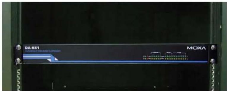
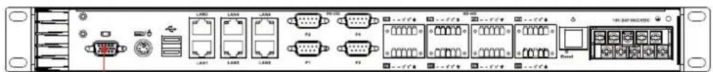
Appearance
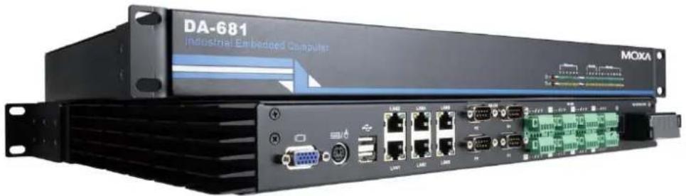
natural_image
Industrial Embedded Computer (DA-681) front panel with visible ports and connectors, no readable text or symbols beyond brandingFront View
Rear View
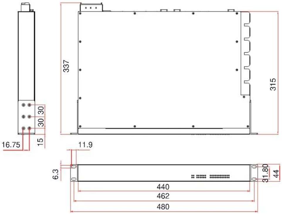
Dimensions
Features
The DA-681 Basic System has the following features:
• IEC 61850-3 certified for power substation automation systems (DPP-T models only)
• Intel Celeron M 1 GHz processor with 400 MHz FSB
- 1 x 200-pin DDR2 SODIMM socket, supporting DDR2 400 up to 1GB (512 Mb built-in)
• Six 10/100 Mbps Ethernet ports
• 1 CompactFlash socket, 1 IDE and serial ATA-150 connectors for storage expansion
• USB 2.0 ports for high speed peripherals
• 4 isolated RS-232 and 8 isolated RS-485 ports
- Serial port speed from 50 to 921.6 Kbps, supporting nonstandard baudrates
- Specific design for heat dissipation
• Embedded Linux, WinCE 6.0, or WinXPe platform
• 19-inch Rackmount model, 1U high
- Wide temperature models available (DPP-T models only)
• 100-240 VAC/VDC power input (Dual Power models offer power redundancy function)
- Fan-less design

ATTENTION
Refer to the “Non-standard Baudrates” section for instructions on how to calculate which baudrates are supported.
Hardware Block Diagram
DA-681 Basic System
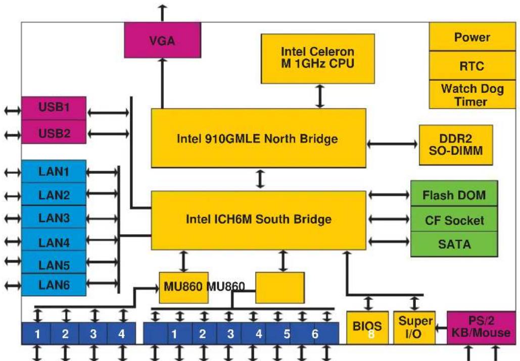
flowchart
graph TD
    A["Intel 910GMLE North Bridge"] --> B["Intel ICH6M South Bridge"]
    B --> C["BU-860 MU860"]
    B --> D["BU-860 MU860"]
    C --> E["BIOS 8"]
    C --> F["Super I/O"]
    C --> G["PS/2 KB/Mouse"]
    H["VGA"] --> A
    I["Intel Celeron M 1GHz CPU"] --> A
    J["Power"] --> A
    K["RTC"] --> A
    L["Watch Dog Timer"] --> A
    M["DDR2 SO-DIMM"] --> A
    N["Flash DOM"] --> B
    O["CF Socket"] --> B
    P["SATA"] --> B
    Q["USB1"] --> A
    R["USB2"] --> A
    S["LAN1"] --> A
    T["LAN2"] --> A
    U["LAN3"] --> A
    V["LAN4"] --> A
    W["LAN5"] --> A
    X["LAN6"] --> A
    Y["1 2 3 4"] --> Z["1 2 3 4 5 6"]
RS-485 x8RS-232 x 4
Hardware Specifications
| DA-681-CE | DA-681-LX | ||
| Computer | |||
| CPU Intel Celeron M 1 GHz processor | |||
| OS (pre-installed) | WinCE 6.0 | Linux 2.6 | Windows XP Embedded SP3 |
| System Chipset Intel 910 GMLE + ICH6M chipset | |||
| FSB 400 MHz | |||
| BIOS | 4 mega-bit Flash BIOS, PCI Plug & Play, ACPI function support | ||
| System Memory 1 x 200-pin DDR2 SODIMM socket supporting DDR2 400; up to 1 GB max. (512 MB built-in) | |||
| DOM: 1 GB (2 GB for DA-681-XPE) industrial DOM onboard to store OS via IDE interface | |||
| HDD Support SATA connector for HDD expansion | |||
| CompactFlash | CompactFlash Type-I/II socket available for storage expansion with DMA mode support | ||
| Other Peripherals | |||
| USB USB 2.0 compliant | hosts x 2, Type A connector, supports system boot up | ||
| KB/MS | 1 PS/2 interface, support standard PS/2 keyboard and PS/2 mouse via Y-type cable (Optional) | ||
| Display | |||
| Graphics Controller | Integrated graphics with built-in Intel 910GMLE, and built-in Intel extreme Graphics 2 technology | ||
| Display Memory | Dynamic video memory (shares up to 32 MB of system memory) | ||
| Display Interface | CRT Interface for VGA output (DB15 female connector) | ||
| Resolution | CRT display mode with pixel resolution up to 2048 x 1536 at 75Hz | ||
| Ethernet Interface | |||
| LAN Auto-scensing 10/100 Mbps Ethernet x 6, using Realtek RTL8110SC Controller | |||
| Magnetic Isolation Protection | 1.5 KV built-in | ||
| Serial Interface | |||
| Number of Ports RS-232 x 4, RS-485 x 8 | |||
| Serial Standards | RS-232, RS-485 | ||
| Connectors | RS-232: DB9 connector, RS-485: terminal block | ||
| ESD protection | 15 KV for all signals | ||
| Optical Isolation Protection | 2 KV | ||
| Serial Communication Parameters | |||
| Data Bits | 5, 6, 7, 8 | ||
| Stop Bits | 1, 1.5, 2 | ||
| Parity | None, Even, Odd, Space, Mark | ||
DA-681-XPE
| Flow Control RTS/CTS, | XON/XOFF, ADDCTM (automatic data direction control) for RS-485 |
| Baudrate 50 bps to 921.6 | Kbps (non-standard baudrates supported; see next page for details) |
| Serial Signals | |
| RS-232 TxD, RxD, DTR, | DSR, RTS, CTS, DCD, GND |
| RS-485-2w Data+, Data-, | GND |
| LEDs | |
| System Power x 1, Storage x 1, Power 1 Fail x 1, Power 2 Fail x 1 | |
| LAN 10 Mbps x 6, 100 Mbps x 6 | |
| Serial RS-232 TX x 4, RX x 4, RS-485 TX x 8, RX x 8 | |
| Physical Characteristics | |
| Enclosure SECC sheet metal (1 mm) | |
| Weight 4.5 kg for SP and DPP models; 4.7 kg for DPP-T models | |
| Dimensions 440 x 253 x 45 mm (17.32 x 9.96 x 1.77 in) | |
| Mounting Standard 19-inch rackmount | |
| Switches and Buttons | |
| Reset Button To reset system hardware (on rear panel) | |
| Environmental Limits | |
| Operating Temperature -10 to 60°C (14 to 140°F) for SP and DP models-40 to 75°C (-40 to 167°F) for DPP-T models | |
| Operating Humidity 5 to 95% RH | |
| Storage Temperature -20 to 80°C (4 to 176°F) for SP and DP models-40 to 85°C (-40 to 185°F) for DPP-T models | |
| Anti-Vibration | 7 mm (2-9 Hz), 20 m/s2 (9-200 Hz), 15 m/s2 (200-500 Hz) @ IEC-61850-3, IEC 60870-2-2/Cm/(3M6)/(4M6), sine wave, 2-500 Hz, 1 Oct/min, 10 Cycles, 2 hrs 40 mins per axis |
| Anti-Shock | 300 m/s2 @ IEC-61850-3, IEC 60870-2-2/Cm/(3M6)/(4M6), half sine wave, 11 ms |
| Power Requirements | |
| Input Voltage | 100 to 240 VAC/VDC auto-ranging (47 to 63 Hz for AC input), single power for SP models, dual power for DP and DDP models; dual power models offer power redundancy function |
| Power Consumption | 50W |
| Input Rating | 100-240VAC, 47-63Hz, 1.0A-0.5A |
| Regulatory Approvals | |
| EMC | CE (EN55022, EN61000-3-2, EN61000-3-3, EN55024), FCC (Part 15 Subpart B, CISPR 22 Class ), CCC (GB9254, GB 17625.1), IEC 61850-3 (DPP-T models only) |
| Safety | UL/cUL (UL60950-1, CSA C22.2 No. 60950-1-03), LVD (EN60950-1), CCC (GB4943) |
| Reliability | |
| Alert Tools | Built-in buzzer and RTC (real-time clock) with battery lithium backup |
| Warranty | |
| Warranty Period | 3 yearsDetails: See www.moxa.com/warranty |
Non-standard Baudrates
Moxa's UART ASIC, supports most non-standard baudrates in the range 50 bps to 921.6 Kbps. In fact, supported baudrates are much denser towards the lower values. For example, no baudrates are supported between the integers 5320 and 5323, but 49 baudrates are supported between the integers 387 and 388. Of course this is the way it should be, since serial devices that require using non-standard baudrates generally use slower baudrates.
Before using a serial device that requires using a non-standard baudrate, you must first check that the DA-681 supports a baudrate within the tolerance specified by the serial device manufacturer.
Use the following formula to calculate which baudrates are supported by the DA-283:
(A) Baudrate = 921600/(N+M/8) bps, for N = 1, 2, ..., 18431, M = 0, 1, 2, ..., 7
or
(B) Baudrate = 8 x 921600/K bps, for K = 8, 9, ..., 147456
If you are a programmer and you need to write a driver for your serial device, then you may need to use formula A. If you have a serial device that requires using a non-standard baudrate, then you can use formula B to determine if the DA-681 supports a baudrate within the tolerance specified by the serial device manufacturer.
Example: Your serial device requires using a baudrate of 5340 bps and has a tolerance of 2 bps. Can the DA-681 be used with this device?
Solution: Set formula B to the desired baudrate and then solve for K.
$$ 8 \mathrm{x} 9 1 2 6 0 0 / \mathrm{K} = 5 3 3 8 \quad = = > \quad \mathrm{K} = 1 3 6 7. 7 0 3 2 5 9 \dots $$
This shows that the supported baudrate closest to 5340 comes from setting K=1367 or K=1368.
$$ \mathrm{K} = 1 3 6 8 \quad = > \quad \text { Baudrate1 } = 5 3 3 6. 8 4 2 1 0 5... $$
$$ \mathrm{K} = 1 3 6 7 \quad = = > \quad \text { Baudrate2 } = 5 3 4 0. 7 4 6 1 5 9 \dots $$
Since 5338 - Baudrate1 < 2 , we can see that the DA-681 supports the serial device.
Note that we can use formula A to generate the so-called “standard” baudrates, which come from setting M=0, and setting N equal to certain integers.
| Standard Baudrates | ||||||
| Baudrate | N | M | Baudrate | N | ||
| 921600 | 1 | 0 | 4800 | 192 | ||
| 460800 | 2 | 0 | 2400 | 384 | ||
| 230400 | 4 | 0 | 1800 | 512 | ||
| 115200 | 8 | 0 | 1200 | 768 | ||
| 57600 | 16 | 0 | 600 | 1536 | ||
| 38400 | 24 | 0 | 300 | 3072 | ||
| 19200 | 48 | 0 | 150 | 6144 | ||
| 9600 | 96 | 0 | 12288 | |||
| 7200 | 128 | 0 | 50 | 18432 | ||

WARNING
Communication between a serial device and a Moxa UART port may not work correctly if the serial device uses a baudrate that it not within the correct tolerance of a baudrate calculated from either formula A or formula B.
The DA-681 Series of embedded computers are compact and rugged, making them suitable for industrial applications. The LED indicators allow users to monitor performance and identify trouble spots quickly, and multiple ports are provided for connecting a variety of different devices. The DA-681 embedded computers come with a reliable and stable hardware platform that lets you devote the bulk of your time to application development. This chapter describes hardware installation and connector interfaces of the DA-681 embedded computers.
This chapter covers the following topics:
□ Placement Options
▶ Desktop
Rack mounting
□ Wiring Requirements
□ Connecting the Power
□ Wiring the Power Inputs
☐ Power Input Wiring Description
☐ HIPOT (Dielectric Strength) Testing
□ Reset Button
Front Panel LED
□ Connecting to a Display
☐ Connecting a PS/2 Keyboard and Mouse
□ Connecting USB Devices
□ LAN Ports
□ Upgrading the Memory Module
□ Installing a CompactFlash Card
□ Installing a SATA Hard Disk
Placement Options
Desktop
Place your DA-681 on a clean, flat, well-ventilated desktop. For better ventilation, leave some space between the DA-681 and other equipment. Do not place equipment or objects on top of the DA-681, as this might damage the computer's internal components.
Rack mounting
The DA-681 has rackmount supports for installing the embedded computer on a standard rack.

ATTENTIONS
- For maximum safety, at least two persons should work together to lift, place, and attach the embedded computer to the rack.
- Before you lift or move the embedded computer, make sure that the embedded computer is turned off and the power to the rack system is turned off.
Four rackmount screws are required to attach the DA-681 to a standard rack.
Follow these steps to install the DA-681 on a rack.
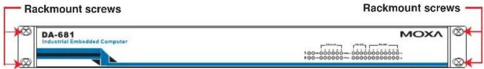
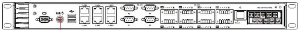
Step 1: Installing the rackmount supports.
Take the rackmount supports out of the packages. There are two rackmount ears and 12 screws. Each ear requires 6 screws to attach to the rack.

natural_image
Black rectangular object with six circular holes, next to a row of metallic circular buttons (no text or symbols visible)Step 2: Installing the rackmount ears to the DA-681.
Use 6 screws to attach one rackmount car to one side of the DA-681. Repeat this procedure for the ear on the other side of the DA-681.
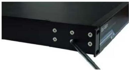
natural_image
Close-up of a black electronic device with screw holes and a cable inserted (no visible text or symbols)Step 3: Installing the DA-681 to a rack.
Gently slide the DA-681 onto the rack, and then use screws provided by the rack supplier to fix the rackmount support to the rail.

natural_image
Close-up of a black server rack with 'MOXA' branding and a metallic screw inserted into a socket (no readable text beyond branding)Note that four screws are required to attach the DA-681 to the rack. Use two screws on the left side and two screws on the right side.
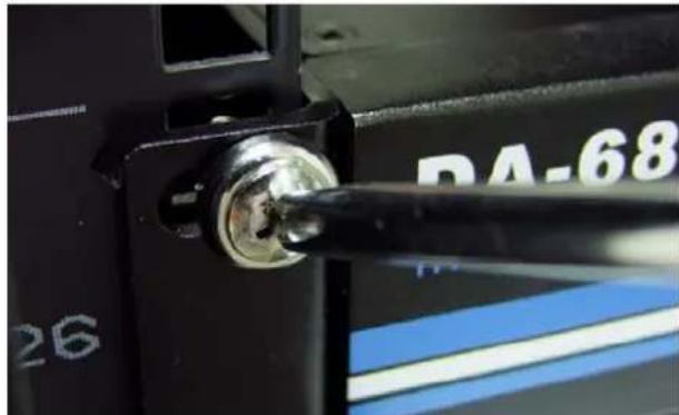
natural_image
Close-up of a mechanical component with a metallic screw and a black tool inserted, showing no visible text or symbols.As a final check, make sure that the four screws are firmly attached to the rack.
Wiring Requirements
The following common safety precautions should be observed before installing any electronic device:
- Use separate paths to route wiring for power and devices. If power wiring and device wiring paths must cross, make sure the wires are perpendicular at the intersection point.
- You can use the type of signal transmitted through a wire to determine which wires should be kept separate. The rule of thumb is that wiring that shares similar electrical characteristics can be bundled together.
- Keep input wiring and output wiring separate.
- When necessary, it is strongly advised that you label wiring to all devices in the system.

ATTENTION
Do not run signal or communication wiring and power wiring in the same wire conduit. To avoid interference, wires with different signal characteristics should be routed separately.

ATTENTION
Safety First!
Be sure to disconnect the power cord before installing and/or wiring your device.
Electrical Current Caution!
Calculate the maximum possible current in each power wire and common wire. Observe all electrical codes dictating the maximum current allowable for each wire size.
If the current goes above the maximum ratings, the wiring could overheat, causing serious damage to your equipment.
Temperature Caution!
Be careful when handling the unit. When the unit is plugged in, the internal components generate heat, and consequently the outer casing may feel hot to the touch.
Connecting the Power
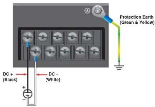
The DA-681 offers both single power and dual power inputs. Use a screwdriver to remove the screws. Connect the power cord to the screws and then attach the screws to the unit. For single models (SP), use Power 1 only; for dual power models (DP and DPP-T), use both Power 1 and Power 2 for power input installation. Refer to the following figure for detailed information.
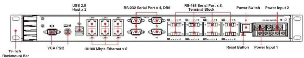
Wiring the Power Inputs
For SP Models
PWR 1
| +/L | NC NC NC | NC | ||
| -/N | ± | NC | NC | NC |
Power 1
AC Terminal
DC Terminal
For DP Models
PWR 1 PWR 2
| +/L | NC | NC | ± | +/L |
| -/N | ± | NC | NC | -/N |
Power 1
Power 2
AC Terminal
DC Terminal
For DPP-T Models
PWR 1 PWR 2
| +/L | NC | 12 | +/L | |
| -/N | 12 | NC | -/N |
Power 1
Power 2
AC Terminal
DC Terminal
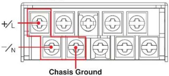
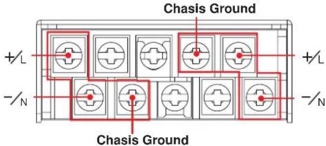
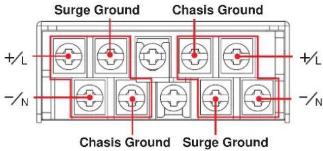
Power Input Wiring Description
Read the following section for a detailed power input wiring description.
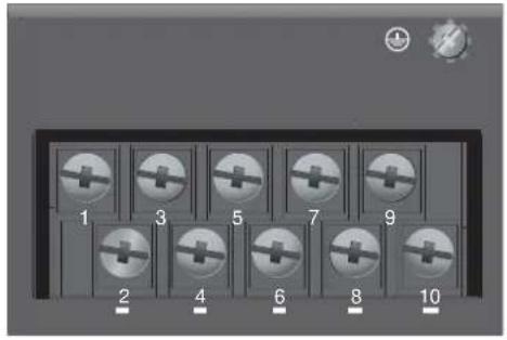
| 1 3 5 7 | 92 | 4 6 8 10 | |||||||
| PWR1 | PWR | 2 | NC | 12 | m | ||||
| +/L | /N | 12 | +/L | /N | |||||
| Terminal Number | Description Note | |
| 1 PWR1 Line / DC + | PWR1 Line / DC + is connected to the positive (+) terminal if the power source is DC, or to theLineterminal if the power source is AC. | |
| 2 PWR1 Neutral / DC - | PWR1 Neutral / DC - is connected to the negative (-) terminal if the power source is DC, or to theNeutralterminal if the power source is AC. | |
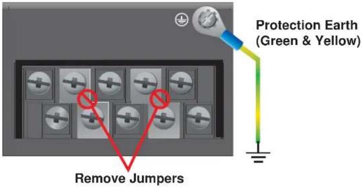
| 3 | PWR1 Surge Ground | PWR1 Surge Groundis connected to the Chassis Ground via a jumper on the terminal block.Surge Groundis used as the ground conductor for all surge and transient suppression circuitry.NOTE:Surge Ground must be disconnected from Chassis Ground during HIPOT (dielectric strength) testing. |
| 4 | Chassis | Chassis Groundis connected to the Safety Ground terminal for AC inputs, or the equipmentground busfor DC inputs.GroundChassis ground connects to both power supply surge grounds via a removable jumper. |
| 5 | NC | No function |
| 6 | NC | No function |
| 7 | Chassis | Chassis Groundis connected to the Safety Ground terminal for AC inputs or theGroundequipmentground busfor DC inputs.Chassis ground connects to both powersupply surge grounds via a removable jumper. |
| 8 | PWR2 Surge Ground is connected to the Chassis Ground via a jumper on the terminal block. Surge Ground is used as the ground conductor for all surge and transient suppression circuitry. NOTE: Surge Ground must be disconnected from Chassis Ground during HIPOT (dielectric strength) testing. | |
| 9 PWR2 Line/ DC + | PWR2 Line / DC + is connected to the positive (+) terminal if the power source is DC, or to the Line terminal if the power source is AC. | |
| 10 PWR2 Neutral / DC - | PWR2 Neutral / DC - is connected to the negative (-) terminal if the power source is DC, or to the Neutral terminal if the power source is AC. | |
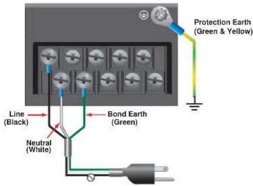
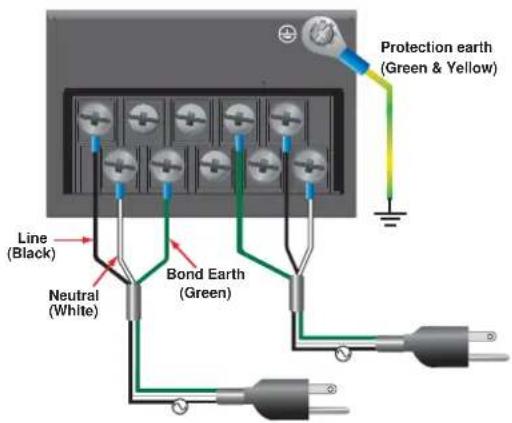
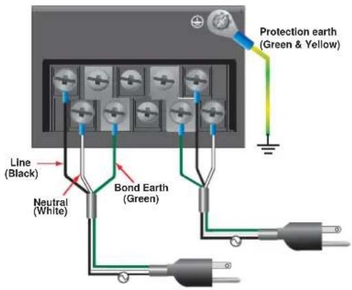
For AC Power Input
- PWR1 Line/ DC + should be connected to AC (Line).
- PWR1 Neutral / DC - should be connected to AC (Neutral).
- Surge Ground is connected to the Chassis Ground via a braided cable or other appropriate grounding wire. Surge Ground is used as the ground conductor for all surge and transient suppression circuitry internal to the PT-7324 unit.
- Chassis Ground should be connected to the AC Ground terminal.

ATTENTION
- Equipment must be installed according to the applicable country wiring codes.
- Surge Ground MUST be disconnected from the Chassis Ground during HIPOT (dielectric strength) testing.
- All line-to-ground transient energy is shunted to the Surge Ground terminal. In cases where users require the inputs to be isolated from the ground, remove the ground braid between Surge and Chassis Ground. Note that all line-to-ground transient protection circuitry will be disabled.
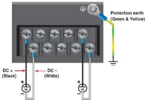
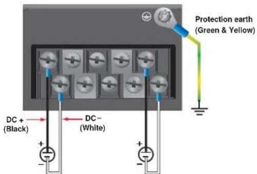
For DC Power Input
The DA-681 series low voltage DC power supply features reverse polarity protection and dual independent inputs. The dual power inputs allow the connection of two DC sources with the same nominal voltage to provide redundant power supply inputs. The DC source must be connected to the DC inputs according to the polarity markings on the unit.

ATTENTION
- Equipment must be installed according to the applicable country wiring codes.
- Surge Ground should be connected to Chassis Ground via a braided cable or other appropriate ground wire.
- Chassis Ground must be connected to the protection earth.
- All line-to-ground transient energy is shunted to the Surge Ground terminal. In cases where users require the DC inputs to be isolated from ground, remove the ground braid between Surge and Chassis Ground. Note that all line-to-ground transient protection circuitry will be disabled.
HIPOT (Dielectric Strength) Testing
Before performing the HIPOT test, you MUST have the jumpers removed and the braided ground cable disconnected. This is required to prevent the transient/surge suppression circuitry, which is connected to Surge Ground from being activated during the HIPOT test.
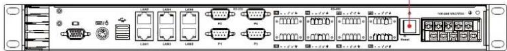
When finished, press the Power Switch button to start the system. It will take about 30 to 60 seconds for your operating system to boot up.
Power Switch
Reset Button
Pressing the Reset button initiates a hardware warm reboot. The button plays the same role as a desktop PC's reset button. After pressing the reset button, the system will reboot automatically. During normal use, you should NOT use the Reset Button. You should only use this button if the software is not working properly. To protect the integrity of data being transmitted or processed, you should always reset the system from the operating system with the software reboot function.
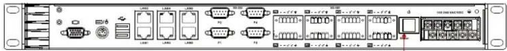
Reset Button
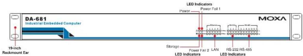
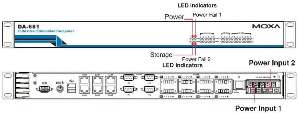
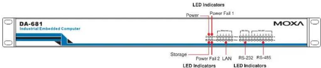
Front Panel LED
There are 40 LED indicators on the front panel. Information about each LED is given in the following table.
| LED Name | Color | LED Description |
| Power | Green Power | is on |
| Off No power | input or power error | |
| Storage | Yellow / Blinking | Data is being written to or to read from the storage unit |
| Off Storage unit is idle | ||
| 100 Mbps | Green 100 Mbps of Ethernet Port is active Ethernet Port | |
| Off | No activity | |
| 10 Mbps | Yellow 10 Mbps of Ethernet Port is active Ethernet Port | |
| Off | No activity | |
| Serial Port TX 1-12 | Green Serial port is transmitting data | |
| Off | No operation | |
| Serial Port RX 1-12 | Yellow Serial port is receiving data | |
| Off | No operation | |
| Power Fail 1 | Red Power 1 fails (For dual power models only) | |
| Off Power works well | ||
| Power Fail 2 | Red Power 2 fails (For dual power models only) | |
| OFF Power works well | ||
Connecting to a Display
Your DA-681 embedded computer comes with a D-Sub 15-pin female connector to connect to the VGA monitor. Be sure to remove the power before you connect or disconnect the monitor cable.
VGA
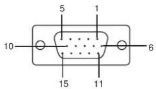
| Pin No. | Signal Definition |
| 1 | RED |
| 2 | GREEN |
| 3 | BLUE |
| 4 | --- |
| 5 | GND |
| 6 | CRT_DETECT# |
| 7 | GND |
| 8 | GND |
| 9 | +5V |
| 10 | GND |
| 11 | --- |
| 12 | DDC_DATA |
| 13 | HSYNC |
| 14 | VSYNC |
| 15 | --- |
Connecting a PS/2 Keyboard and Mouse
Your DA-681 embedded computer comes with a PS/2 mini-DIN connector to connect to a PS/2 keyboard and PS/2 mouse by using a Y-type cable. This 6-pin mini-DIN connector has the pin assignments shown below.
PS/2 Keyboard/Mouse
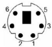
| Pin No. | Signal Definition | ||
| 1 | PS/2 | Keyboard | Data |
| 2 | PS/2 | Mouse | Data |
| 3 | GND | ||
| 4 | VCC | ||
| 5 | PS/2 | Keyboard | Clock |
| 6 PS/2 Mouse Clock | |||
Use the Y-type cable to convert the mini-DIN connector into two 6-pin mini-DIN connectors to connect both a PS/2 keyboard and PS/2 mouse at the same time. (The Y-type cable is not included in the accessory package. It should be purchased separately. You may also use the USB ports to connect your USB-based keyboard and mouse.)


ATTENTION
Please note that without the Y-type cable, the PS/2 connector on the DA-681 can only work with a PS/2 keyboard. A PS/2 mouse will not function when directly connected to the PS/2 connector on the DA-681 embedded computer.
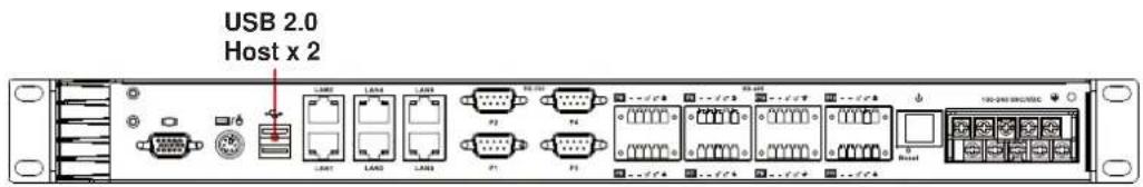
Connecting USB Devices
The DA-681 embedded computer has two USB 2.0 ports on the rear panel. All of the ports are UHCI, Rev 2.0 compliant and support Plug & Play and hot swapping. These ports can be used to connect USB devices, such as a keyboard, mouse, USB flash disk, and USB CD-ROM. In addition, both USB ports support system boot up, which can be activated by modifying the BIOS settings. The chapter “BIOS Setup” describes the configuration process in detail.
LAN Ports
The DA-681 has 6 10/100 Mbps LAN ports. When the cable is properly connected, the LEDs on the RJ45 connectors will glow to indicate a proper connection.
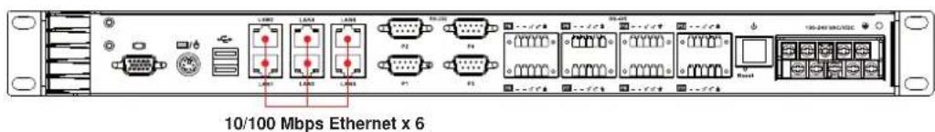
| Pin No. | Signal Definition |
| 1 | TX+ |
| 2 | TX- |
| 3 | RX+ |
| 4 | --- |
| 5 | --- |
| 6 | RX- |
| 7 | --- |
| 8 | --- |
| LED | Color | Description |
| 100 Mbps | Green 100 Mbps of Ethernet Port is active Ethernet Port | |
| Off | No activity | |
| 10 Mbps | Yellow 10 Mbps of Ethernet Port is active Ethernet Port | |
| Off | No activity | |
The default IP addresses and netmasks of the Gigabit LAN ports are as follows:
| Default | IP | Addr | ||
| LAN 1 | 192.16 | 8.3.127 | 255.255.255.0 | |
| LAN 2 | 192.16 | 8.4.127 | 255.255.255.0 | |
| LAN 3 | 192.16 | 8.5.127 | 255.255.255.0 | |
| LAN 4 | 192.16 | 8.6.127 | 255.255.255.0 | |
| LAN 5 | 192.16 | 8.7.127 | 255.255.255.0 | |
| LAN 6 | 192.16 | 8.8.127 | 255.255.255.0 | |
Netmask
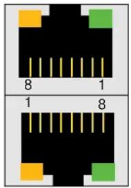
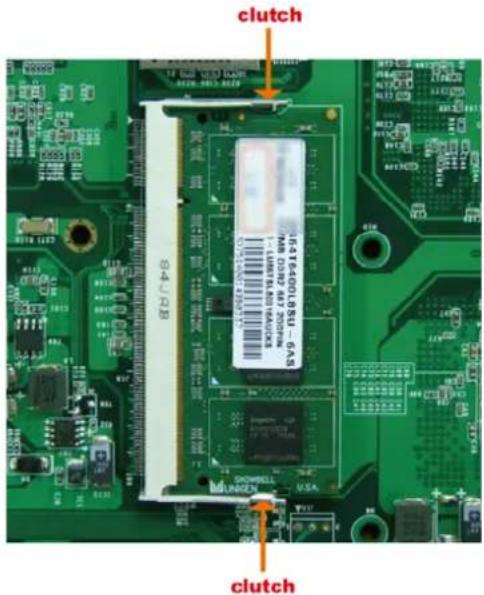
Upgrading the Memory Module
The DA-681 embedded computer supports one 200-pin DDR2 400/533 SODIMM module, up to 1 GB. One DDR2 SDRAM memory module is pre-installed. To upgrade the DDR2 SDRAM memory module, follow these instructions:
- Disconnect the DA-681 from the power source.
- The DA-681's memory module is located inside the DA-681. Use a screwdriver to remove the screws on the top cover of the DA-681.
- After removing the memory module cover, you will see the DDR2 SDRAM module.
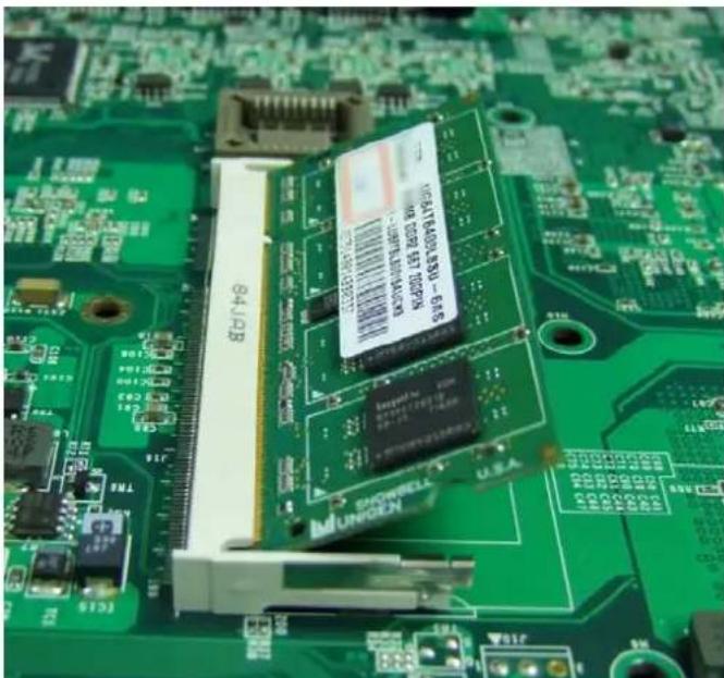
However, DDR2 SDRAM memory has been installed already. To upgrade the memory, you need to remove the original memory by pushing two clutches at both sides of the module.
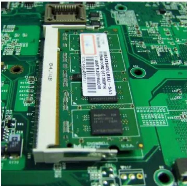
Gently insert the new memory into the module. Make sure the direction is correct.
natural_image
Close-up of a green printed circuit board with electronic components and a central chip (no readable text or symbols)Push the memory all the way down to complete.
Installing a CompactFlash Card
The DA-681 embedded computer comes with a CompactFlash socket. To insert a CompactFlash card, follow these instructions.
-
Disconnect the DA-681 from its power source.
-
The DA-681's CompactFlash socket is located inside the DA-681. Use a screwdriver to remove all the screws on the top cover of the DA-681.
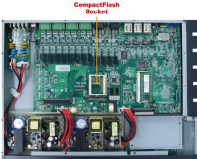
- Insert the CompactFlash card into the socket. Push downwards to make sure that the card is firmly inserted.
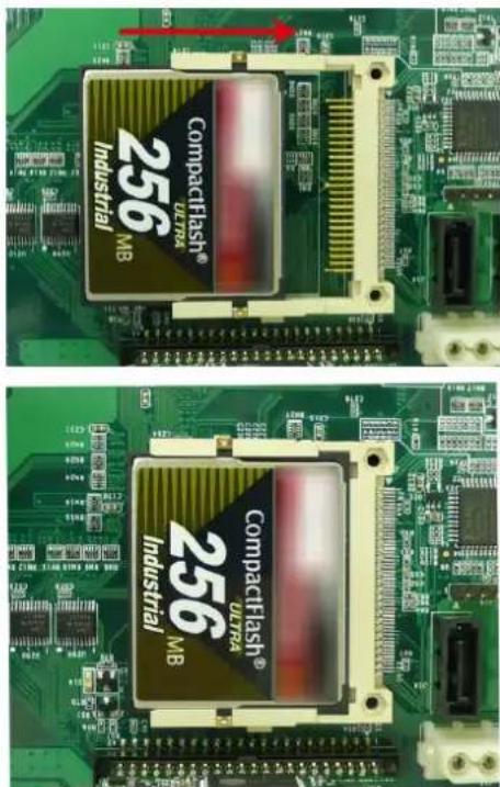

ATTENTION
Make sure you insert the card in the right direction. The card cannot be inserted if you insert the card in the wrong direction.

ATTENTION
The DA-681 embedded computer does not support the CompactFlash hot swap and PnP (Plug and Play) functions. It is necessary to remove power source first before inserting or removing the CompactFlash card.
Installing a SATA Hard Disk
The DA-681 embedded computer has one SATA connector for installing a SATA hard disk. To install a 2.5-inch SATA hard disk, follow these instructions.
- Disconnect the DA-681 from its power source.
- Open the top cover of the DA-681. A hard disk bracket is located on the right side of the DA-681.
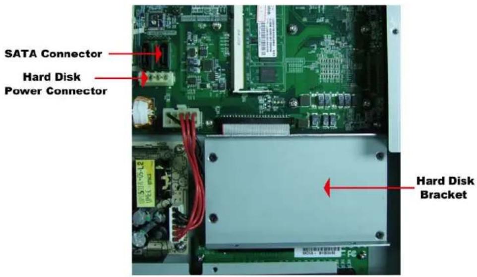
- Use a screwdriver to remove the four screws on the hard disk bracket.
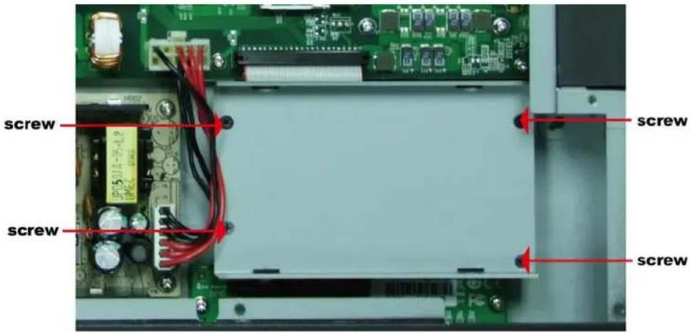
- Install the SATA hard disk in the hard disk bracket.

- Next, install the SATA hard disk and hard disk bracket back into the DA-681. Make sure the screws are firmly attached.
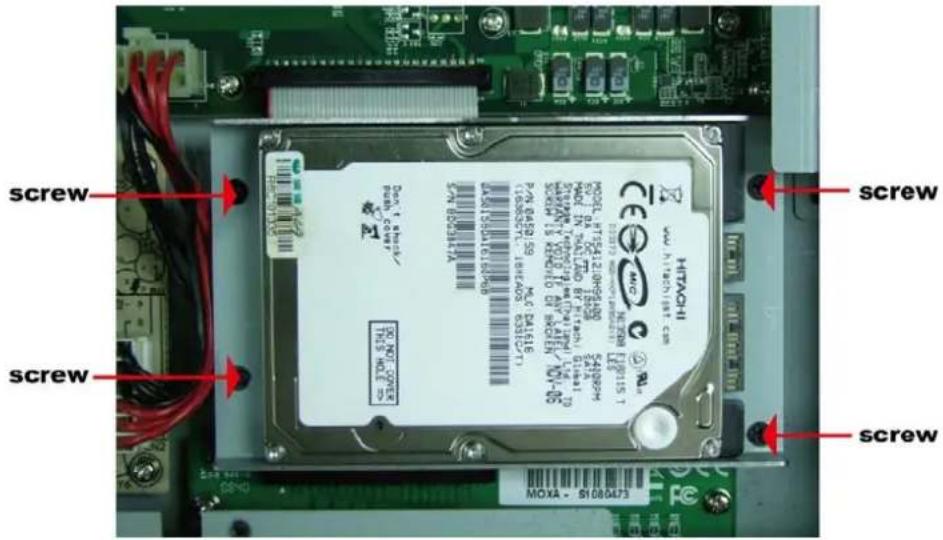
- Connect the SATA disk cable and power cable to the SATA hard disk.
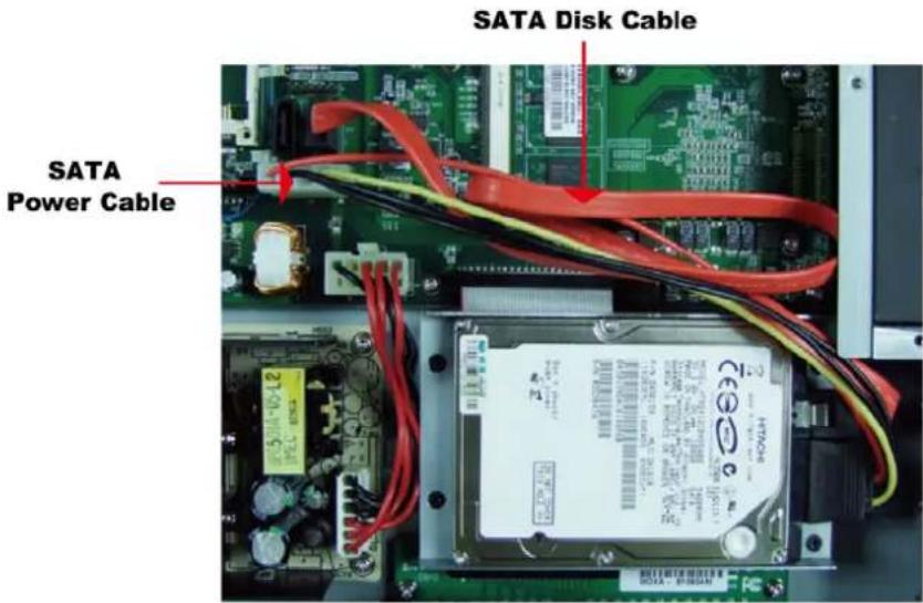

ATTENTION
The SATA hard disk cable and SATA power cable are not included in the basic shipment of the DA-681 embedded computer. Any standard SATA disk cable and power cable can be used.
This chapter describes the BIOS settings of the DA-681 embedded computers. The BIOS is a set of input/output control routines for peripherals. The BIOS is used to initialize basic peripherals and helps boot the operating system before the operating system is loaded. The BIOS setup allows the user to modify the system configurations of these basic input/output peripherals. All of the configurations will be stored in the battery backed up CMOS RAM, which retains the system information after system reboots or the power is removed.
This chapter covers the following topics:
☐ Entering the BIOS Setup Utility
□ Modifying the BIOS Main Settings
▶ Basic Configuration
System Security
□ Advanced Settings
▶ Hard Disk Boot Priority
▶ Advanced BIOS Features
▶ CPU Features
▶ Advanced Chipset Settings
➢ PnP/PCI Configurations
➢ Frequency/Voltage Control
□ Peripherals
OnChip IDE Device
Onboard Device
Onboard I/O Chip Setup
Power
➢ Wake Up Control
Hardware Monitor
Load Defaults
□ Exiting the BIOS Setup
□ Upgrading the BIOS
Entering the BIOS Setup Utility
To enter the BIOS setup utility, press the "Del" key while the system is booting up. The main BIOS Setup screen will appear.
A basic description of each function key is listed at the bottom of the screen. Refer to these descriptions to learn how to scroll about the screen, how to select by pressing "Enter," and how to use the other hot keys listed below.
F1: General Help
F5: Previous Value
F6: Default Settings
F7: Turbo Settings
F10: Save
ESC: Exit
![Phoenix - AwardBIOS CMOS Setup Utility Main Advanced Peripherals Power HW Monitor Defaults Exit Date (mm:dd:yy) Mon, Feb 19 2007 Time (hh:mm:ss) 4 : 1 : 15 ► IDE Channel 0 Master [ST3160815A] ► IDE Channel 0 Slave [ None] Video [EGA/VGA] Halt On [All , But Keyboard] ► Security Base Memory 640K Extended Memory 1038336X Total Memory 1039360K Item Help Menu Level ► : : to select field <->> : <+> : : : <0-9> : to set date ↑↓++:Move Enter:Select +/-/PU/PD:Value F10:Save ESC:Exit F1:General Help F5:Previous Values F6:Default Settings F7:Turbo Settings](/content/2026/05/1142186/images/39a3176df565d0fbfd3992459b5aba9be7d7a086856f5e314267bcb61aa66ab0.jpg)
Modifying the BIOS Main Settings
Basic Configuration
After entering the BIOS Setup, or choosing the “Main” option, the BIOS main menu will be displayed. Use this menu to check the basic system information such as memory and IDE hard drive. You can also use the menu for configuring basic system parameters, such as date, time, hard drive, display, and system security.
System Security
To set up system security, select the "Security" option under "Main" to bring up the following screen.
| Security | Item Help | |
| Set Password Security Option | [Press Enter] [Setup] | Menu Level ▶▶ Change/Set/Disable Password |
| ↑↓++:Move Enter:Select +/-/PU/PD:Value F10:Save ESC:Exit F1:General Help F5:Previous Values F6:Default Settings F7:Turbo Settings | ||
This menu includes two options: "Set Password" and "Security Option."
When you select the Set Password option, a pop-up "Enter Password:" window will appear on the screen. The password that you type will replace the password stored in the CMOS memory. You will be required to confirm the new password. Just re-type the password and then press
To clear an existing password, just press
Once a password has been set, you will be prompted to enter the password each time you enter Setup. This prevents unauthorized persons from changing any part of your system configuration. In addition, when a password setting is enabled, you can set up the BIOS to request a password each time the system is booted up. The “Security Option” setting determines when a password prompt is required. If the “Security Option” is set to “System,” the password must be entered both at boot up and when entering the BIOS Setup Menu. If the password is set for “Setup,” the password prompt only occurs when you enter the “BIOS Setup Menu.”
Advanced Settings
The “Advanced Features” screen will appear when choosing the “Advanced” item from the main menu.
| Phoenix - AwardBIOS CMOS Setup Utility | |
| Main Advanced Peripherals Power HW Monitor Defaults Exit | |
| ► Hard Disk Boot Priority First Boot Device [CDROM] Second Boot Device [Hard Disk] Third Boot Device [Removable] Boot Other Device [Enabled] | Item Help |
| Menu Level ► Select Hard Disk Boot Device Priority | |
| ► Advanced BIOS Features ► Advanced Chipset Features ► PnP/PCI Configurations ► Frequency/Voltage Control | |
| ↑↓+←:Move Enter:Select +/-/PU/PD:Value F10:Save ESC:Exit F1:General Help F5:Previous Values F6:Default Settings F7:Turbo Settings | |
Hard Disk Boot Priority
First/Second/Third Boot Device
This option allows users to select or change the device boot priority. You may set 3 levels of priority to determine the boot up sequence for different bootable devices, such as a hard drive, CD-ROM, and removable devices. Select the order in which devices will be searched in order to find a boot device. The available options are “CDROM (default for first boot device),”
"Removable" (default for third boot device), "Hard Disk" (default for second boot device) and "Disabled."
Boot Other Devices
This setting allows the system to try to boot from other devices if the system fails to boot from the 1st, 2^nd , or 3rd boot devices. The options are "Enabled" (default) and "Disabled.".
Advanced BIOS Features
When you select the "Advanced BIOS Features" option under the "Advanced" menu, the following configuration menu will appear.
| Advanced BIOS Features | Item Help |
| CPU Feature Virus Warning [Disabled] CPU L1 & L2 Cache [Enabled] Quick Power On Self Test [Enabled] Boot Up NumLock Status [On] Typematic Rate Setting [Disabled] × Typematic Rate (Chars/Sec) 6 × Typematic Delay (Msec) 250 APIC Mode [Enabled] MPS Version Control For OS[1.4] OS Select For DRAM > 64MB [Non-OS2] | Menu Level ▶ |
| ↑↓++:Move Enter:Select +/-PU/PD:Value F18:Save ESC:Exit F1:General Help F5:Previous Values F6:Default Settings F7:Turbo Settings | |
CPU Features
Virus Warning
This item allows you to choose the VIRUS warning feature for IDE hard disk boot sector protection. If this function is enabled and someone attempts to write data into this area, the BIOS will display a warning message on the screen and sound an audio alarm (beep).
Options: Disabled (default), Enabled.
CPU L1 & L2 Cache
Make the CPU internal cache active or inactive. System performance may degrade if you disable this item.
Options: Enabled (default), Disabled.
Quick Power on Self Test
This setting allows the system to skip certain tests while the system boots up. Enable this feature to speed up the boot up process.
Options: Enabled (default), Disabled.
Boot Up NumLock Status
Select the power on state for NumLock.
Options: On (default), Numpad keys are number keys.
Off, Numpad keys are arrow keys.
Typematic Rate Setting
When “Enabled” both “Typematic Rate” and “Typematic Delay” can be configured. Typematic Rate determines the keystroke repeat rate used by the keyboard controller.
Options: Disabled (default), Enabled
Typematic Rate (Chars/Sec)
The rate at which the keyboard will repeat a keystroke if users press key continuously.
Typematic Delay (milliseconds)
The delay before keystrokes begin to repeat.
Options: 250 ms (default), 500 ms, 750 ms, 1000 ms
APIC Mode
Set the "Advanced Programmable Interrupt Controller" as active or inactive.
Options: Disabled, Enabled (default)
MPS Version Control for OS
Set the “Multi-Processor Specification.” 1.1 was the original specification. MPS version 1.4 adds extended configuration tables for improved support for multiple PCI bus configurations and greater expandability. In addition, MPS 1.4 introduces support for a secondary PCI bus without requiring a PCI bridge.
Options: 1.1, 1.4 (default)
OS Select for DRAM > 64 MB
Select "OS2" only if you are running the OS/2 operating system with greater than 64 MB of RAM.
Options: Non-OS2 (default), OS2
![Phoenix - AwardBIOS CMOS Setup Utility Advanced CPU Feature Execute Disable Bit [Enabled] Menu Level ▶▶ When disabled, forces the XD feature flag to always return 0. ↑↓++:Move Enter:Select +/-/PU/PD:Value F10:Save ESC:Exit F1:General Help F5:Previous Values F6:Default Settings F7:Turbo Settings](/content/2026/05/1142186/images/7b39a3e1940e3ed0c053ba841042e0a562d4bf66aa3ada3b440a6192e03de681.jpg)
Execute Disable Bit
Intel hardware-based security feature can help reduce system exposure to viruses and malicious code.
Options: Enabled (default), Disabled.
Advanced Chipset Settings
| Advanced Chipset Features | Item Help |
| System BIOS Cacheable [Enabled] Video BIOS Cacheable [Disabled] Memory Hole At 15M-16M [Disabled] ** VGA Setting ** On-Chip Frame Buffer Size [8MB] DVMT Mode [DVMT] DVMT/FIXED Memory Size [128MB] | Menu Level ▶ |
| ↑↓++:Move Enter:Select +/-/PU/PD:Value F10:Save ESC:Exit F1:General Help F5:Previous Values F6:Default Settings F7:Turbo Settings | |
System BIOS Cacheable
The BIOS ROM addresses F0000h to FFFFFh are cached, and the cache controller is enabled to access the system. Enable it to speed up system performance.
Options: Enabled (default), Disabled
Video BIOS Cacheable
Enabling this feature allows the caching of the video BIOS and may improve performance. A system error could occur if another program writes to this memory cache area.
Options: Enabled, Disabled (default)
Memory Hole at 15M-16M
When enabled, the system will reserve a system memory area for the ISA adapter ROM, and this memory area will not be available for caching.
Options: Enabled, Disabled (default)
On-Chip Frame Buffer Size
This item determines the frame buffer size for the VGA function, and will share the system memory.
Options: 1 MB, 8 MB (default)
DVMT Mode
Setting the DVMT operating mode. When set to “Fixed,” the graphics driver will reserve a fixed portion of the system memory as graphics memory. When set to “DVMT,” the graphics driver will dynamically allocate system memory as graphics memory, according to system and graphics requirements. When set to “BOTH,” the graphics driver will allocate a fixed amount of memory as dedicated graphics memory, as well as allow more system memory to be dynamically allocated between the graphics processor and the operating system.
Options: FIXED, DVMT (default), BOTH
DVMT/FIXED Memory Size
Sets the maximum amount of system memory that can be allocated as graphics memory.
Options: 64 MB, 128 MB (default).
PnP/PCI Configurations
| Phoenix - AwardBIOS CMOS Setup Utility Advanced | |
| PnP/PCI Configurations | Item Help |
| Init Display First [PCI] Resources Controlled By [Auto] × IRQ Resources PCI/VGA Palette Snoop [Disabled] PCI Latency Timer(CLK) [32] | Menu Level ▶ |
| ↑↓++:Move Enter:Select +/-/PU/PD:Value F10:Save ESC:Exit F1:General Help F5:Previous Values F6:Default Settings F7:Turbo Settings | |
Init Display First
This item allows you to decide whether the PCI interface or onboard graphic chip is activated first.
Options: PCI (default), Onboard
Resources Controlled By
The BIOS can automatically configure all boot and Plug and Play compatible devices. If you choose Auto, you will not be able to assign IRQ and memory base address fields manually, since the BIOS assigns them automatically.
Options: Auto (default), Manual
IRQ Resources
When resources are controlled manually, you can assign each system interrupt to Reserved or PCI device. This is only configurable when “Resources Controlled By” is set to “Manual.”
Options: IRQ 3, 4, 5, 7, 10, 11 for PCI device.
PCI/VGA Palette Snoop
This item can be used to fix the color display error of non-standard VGA display adaptors such as graphics accelerators or MPEG video cards.
Options: Disabled (default), Enabled
PCI Latency Timer (CLK)
Configure PCI Latency Time to optimize the PCI speed. The range of possible values is "0" to "255" with a default value of "32."
Frequency/Voltage Control
| Frequency/Voltage Control | Item Help |
| Spread Spectrum [Enabled] | Menu Level ▶ |
Spread Spectrum
Select "Enabled" to reduce EMI (Electromagnetic Interference). The default is "Enabled."
Peripherals
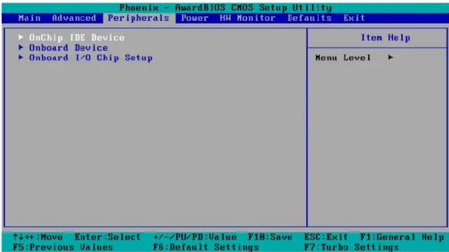
OnChip IDE Device
| OnChip IDE Device | Item Help | |
| IDE HDD Block Mode [Enabled] On-Chip Channel 0 PCI IDE [Enabled] IDE Channel 0 Master PIO [Auto] IDE Channel 0 Slave PIO [Auto] IDE Channel 0 Master UDMA [Auto] IDE Channel 0 Slave UDMA [Auto] On-Chip Channel 1 PCI IDE [Enabled] IDE Channel 1 Master PIO [Auto] IDE Channel 1 Slave PIO [Auto] IDE Channel 1 Master UDMA [Auto] IDE Channel 1 Slave UDMA [Auto] | Menu Level ▶▶ If your IDE hard drive supports block mode select Enabled for automatic detection of the optimal number of block read/writes per sector the drive can support | |
| ↑↓++:Move Enter:Select +/-/PU/PD:Value F10:Save ESC:Exit F1:General Help F5:Previous Values F6:Default Settings F7:Turbo Settings | ||
IDE HDD Block Mode
Block mode is otherwise known as block transfer, multiple commands, or multiple sector read/write. Select the “Enabled” option if your IDE hard drive supports block mode (most new drives do). The system will automatically determine the optimal number of blocks to read and write per sector.
Options: Enabled (default), Disabled
On-Chip Channel 0/1 PCI IDE
This item lets users enable or disable the IDE channel.
Options: Disabled, Enabled (default)
IDE Channel 0/1 Master/Slave PIO
The IDE PIO (Programmed Input/Output) fields let you set a PIO mode (0-4) for each of the IDE devices that the onboard IDE interface supports. Modes 0 to 4 will increase performance incrementally. In Auto mode, the system automatically determines the best mode for each device.
Options: Auto (default), Mode0, Mode1, Mode2, Mode3, Mode4
IDE Channel 0/1 Master/Slave UDMA
Ultra DMA functionality can be implemented if it is supported by the IDE hard drives in your system. Your operating environment also requires a DMA driver (Windows 95 OSR2 or a third party IDE bus master driver). If your hard drive and your system software both support Ultra DMA, select "Auto" to enable BIOS support.
Options: Auto (default), Disabled
Onboard Device
| Phoenix - AwardBIOS CMOS Setup Utility Peripherals | |
| Onboard Device | Item Help |
| USB Controller [Enabled] USB 2.0 Controller [Enabled] USB Keyboard Support [Disabled] Onboard LAN Boot ROM [Disabled] | Menu Level ▶▶ |
| ↑↓++:Move Enter:Select +/-/PU/PD:Value F10:Save ESC:Exit F1:General Help F5:Previous Values F6:Default Settings F7:Turbo Settings | |
USB Controller
This feature allows you to enable/disable the USB controller.
Options: Enabled (default), Disabled
USB 2.0 Controller
This feature allows you to enable/disable the USB 2.0 controller.
Options: Enabled (default), Disabled
USB Keyboard Support
This item is useful for DOS systems. Enable it if you want to use a USB keyboard under a DOS environment.
Options: Enabled, Disabled (default)
Onboard LAN Boot ROM
Decide whether to invoke the boot ROM of the onboard LAN chip.
Options: Enabled, Disabled (default)
Onboard I/O Chip Setup
| Onboard I/O Chip Setup | Item Help |
| Debug Port [Disabled] PHRON After PWR-Fail [On] | Menu Level ▶▶ |
| ↑↓++:Move Enter:Select +/-/PU/PD:Value F10:Save ESC:Exit F1:General Help F5:Previous Values F6:Default Settings F7:Turbo Settings | |
Debug Port
Select an address and corresponding interrupt for this debug port. This port is only for engineers who are debugging programs.
Options: Disabled (default), 3F8/IRQ4
PWRON after PWR-Fail
This field determines whether your system will boot after restoring power from a power failure. If you select "On," the system will boot after restoring power from a power failure. If you select "Former-Sts" (Former Status), the system will boot or not, depending on the status before the power failure.
Options: Off, On (default), Former-Sts.
Power
The Power Setup Menu allows you to configure your system power-up/ power-down options.
![Phoenix - AwardBIOS CMOS Setup Utility Main Advanced Peripherals Power HW Monitor Defaults Exit Soft-Off by PWR-BTTN [Instant-Off] ► Wake Up Control Item Help Menu Level ► ↑↓→+:Move Enter:Select +/-/PU/PD:Value F10:Save ESC:Exit F1:General Help F5:Previous Values F6:Default Settings F7:Turbo Settings](/content/2026/05/1142186/images/9cd56ecde93202d110971ee86ac28441103a86a86ed3b7fd33441f0da0548ac2.jpg)
Soft-Off by PWR-BTTN
Select the “Instant-Off” option if you would like the system to power down immediately after pushing the power button. Selecting the “Delay 4 Sec” option will require pushing the power button continuously for at least 4 seconds before the system powers down.
Options: Delay 4 Sec, Instant-Off (default).
Wake Up Control
Press "Enter" to select Wake Up Control items.
Lan Wake up
This feature is used to wake up the system by a LAN device from a remote host.
Please note that this function only works for LAN Port 5 and Port 6.
Options: Disabled (default), PCI
RTC Wake Up
When “Enabled,” you can set the date and time at which the RTC (real-time clock) alarm awakens the system from Suspend mode.
Options: Disabled (default), Enabled.
Date (of Month) Alarm
Set the "date" for the "RTC Wake Up" function when "RTC Wake Up" is set to "Enabled."
Time (hh: mm: ss) Alarm
You can set the hour, minute, and second of the "RTC Wake Up" function when "RTC Wake Up" is set to "Enabled."
Hardware Monitor
| CPU Warning Temperature [90°C/194°F] Warning Beep [Disabled] Current System Temp 33°C/ 91°F Current CPU Temperature 41°C/105°F CPU Vcore 8.93V Vccp 1.07V NB Vcore 1.08V DDR2 Vcore 1.88V +5.0 (U) 4.96V +3.3 (U) 3.29V AVCC (U) 3.29V VBAT (U) 3.08V 3USB (U) 2.91V | Item Help |
| Menu Level ▶ | |
| ↑↓→+:Move Enter:Select +/-/PU/PD:Value F10:Save ESC:Exit F1:General Help F5:Previous Values F6:Default Settings F7:Turbo Settings | |
CPU Warning Temperature
This item sets the CPU warning temperature. When the CPU temperature is higher than this setting, the system will throttle down to 75%. When the CPU temperature is higher than this setting plus 10°C, the system will throttle down to 50%.
Options: 80°C/176°F, 90°C/194°F (default), 100°C/212°F, Disabled.
Warning Beep
Set the beep to sound or not sound when the CPU temperature is over the CPU warning temperature.
Options: Disabled (default), Enabled.
Load Defaults
| Phoenix - AwardBIOS CMOS Setup Utility | |
| Main Advanced Peripherals Power HW Monitor Defaults Exit | |
| Load System Default Settings Load System Turbo Settings Load CMOS From BIOS Save CMOS To BIOS | Item Help |
| Menu Level ▶ Load System Default Settings | |
| ↑↓++:Move Enter:Select +/-/PU/PD:Value F10:Save ESC:Exit F1:General Help F5:Previous Values F6:Default Settings F7:Turbo Settings | |
Load System Default Settings
Use this option to load system factory default settings instead of the current BIOS settings. This option is useful for when the system is unstable. Users do not need to remember what settings were active before the system fails.
Load System Turbo Settings
Use this option to load system optimized settings. If the system is not stable, please load the system default settings.
Load CMOS from BIOS
Use this option to load BIOS settings from flash ROM to CMOS.
Save CMOS to BIOS
Use this option to save the BIOS settings from the CMOS to flash ROM.
Exiting the BIOS Setup
To exit the BIOS setup utility, choose "Exit." Pressing
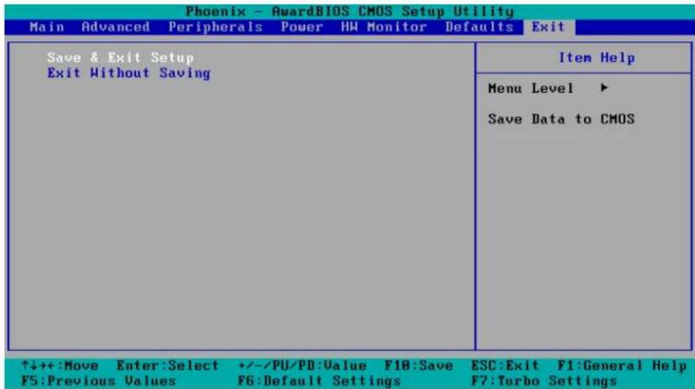
Save & Exit Setup
Save all configuration changes to CMOS (memory) and exit setup. A confirmation message will be displayed before proceeding.
Exit Without Saving
Abandon all changes made during the current session and exit setup. A confirmation message will be displayed before proceeding.
Upgrading the BIOS
This section describes how to upgrade the bios.
Step 1: Create a Bootable USB Disk.
There are two recommended methods for creating a bootable USB disk:
Method 1: Use HP USB Disk Format Tool
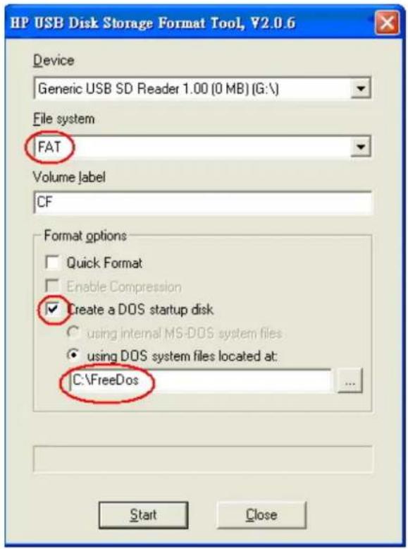
- Download FreeDOS system files kernel.sys and command.com from http://www.freedos.org/kernel/
- Copy DOS system files kernel.sys and command.com to a specified directory (C:\FreeDOS in this example).
- Start the HP USB Disk Storage Format Tool and select the USB device that you want to use as a bootable disk in the Device drop down box.
- Select FAT in the File system drop down box.
- Type the disk name in the Volume label field.
- Check the option Create a DOS startup disk under format options.
- Specify the directory of the system files (for example, C:\FreeDOS).
- Click Start to format and create the USB disk.

ATTENTION
HP's USB Disk Storage Format Tool can be downloaded from many web sites. Use the phrase "HP USB Disk Storage Format Tool" to search the Internet, and then download the tool from one of the websites that is listed.
Method 2: Use the BootFlashDOS utility.
Run the BootFlashDOS utility and then press Start.
![BootFlashDOS CODING BootFlashDOS For Windows XP/2003 http://GoCoding.Com USB FLASH DRIVE USB Device 2063Mb [M:\] Refresh Options : Label : Quick Format Force Volume Dismount Don't rewrite MBR code Enable LBA (Fat16X) Start...](/content/2026/05/1142186/images/aa92f4e763e151e97195e1551e1347bcf2690556fe278dea0889c0c5ff9f97b2.jpg)

ATTENTION
The BootFlashDOS utility can be downloaded from the following website: http://gocoding.com/page.php?al=bootflashdos.
Step 2: Prepare the Upgrade Tool and BIOS Binary File.
You must use the BIOS upgrade installation file to upgrade the BIOS. You can download it from the Moxa Download Center at:
http://web4.moxa.com/support/download_center.asp
- Get the BIOS upgrade installation file. The file name should have following format: BIOS_DA-68X_V1.0_Build_08042310.zip.
- Copy the file to the Bootable USB Disk.
- Double click to extract the BIOS update installation file. The file includes a binary file in the form xxxxxxx.Sxx and the upgrade utility named awdflash.exe.
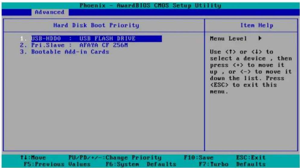
Step 3: Set up the BIOS to Boot from the USB Disk.
- Insert the USB disk.
- Power on and press DEL to enter the BIOS Setup menu.
- Select Advanced → Hard Disk Boot Priority and then press Enter.
- From the Setup menu, use “↑” or “↓” to select the USB device.
- Press "+" to move it up to the first priority, and press "Esc" to exit the setup menu.
- Make sure the first boot device is Hard Disk. If it isn't, press Enter to change it.
- Select Exit → Save & Exit Setup and then press Enter.
- Choose Y to save to the CMOS and then exit.
![Phoenix - AwardBIOS CMOS Setup Utility Main Advanced Peripherals Power HW Monitor Defaults Exit ► Hard Disk Boot Priority First Boot Device [Hard Disk] Second Boot Device [Hard Disk] Third Boot Device [Removable] Boot Other Device [Enabled] ► Advanced BIOS Features ► Advanced Chipset Features ► PnP/PCI Configurations ► Frequency/Voltage Control Item Help Menu Level ► Select Your Boot Device Priority. Please set 'Peripherals → Onboard Device → Onboard LAN Boot ROM' to enable when you would like to boot from onboard Lan. ↑↓→+:Move Enter:Select +/-/PU/PD:Value F10:Save ESC:Exit F1:General Help F5:Previous Values F6:Default Settings F7:Turbo Settings](/content/2026/05/1142186/images/58558e10a894840f31f156a97849df891d01d4d38ad5f27c80ea7358f515aa78.jpg)
Step 4: Run awdflash.exe to upgrade the BIOS.
-
If the BIOS Setup is correct, it will restart and boot from the USB disk.
-
Run awdflash xxxxxxx.Sxx from the command line to upgrade the BIOS. Replace xxxxxxx.Sxx with the BIOS binary file name discussed in Step 2.
-
Press F1 to reset the system after the bios update is complete. The system should reboot at this time.
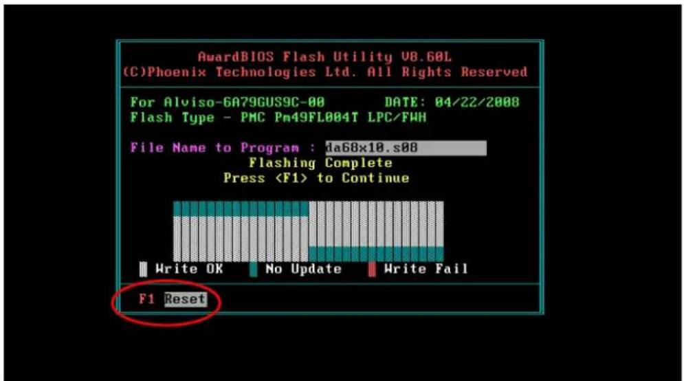

ATTENTION
Do NOT switch off the power supply during the BIOS upgrade, since doing so may cause the system to crash.
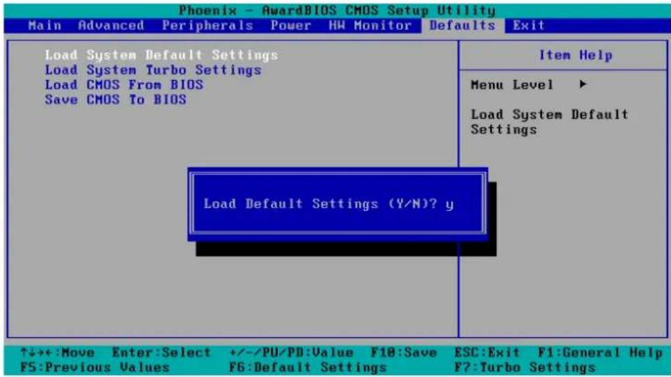
Step 5: Load BIOS Default.
- When the system reboots, the user should load the CMOS Setup default value again.
- Press DEL to open the BIOS Setup menu.
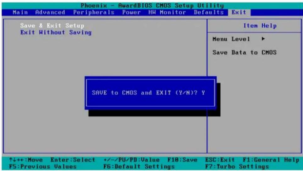
- Select Defaults → Load System Default Settings and then choose Y.
- Select Exit → Save & Exit Setup and then press Enter to choose Y to save the settings to CMOS and exit.
A. RTC Battery Warning
CAUTION: There is a risk of explosion if battery is replaced by an incorrect type. Dispose of used batteries according to the instructions.
B. Fuse Warning
CAUTION: For continued protection against fire, replace only with same type and rating of fuse.
C. Rackmount Warning
The following or similar rackmount instructions are included with the installation instructions:
(1) Elevated Operating Ambient: If installed in a closed or multi-unit rack assembly, the operating ambient temperature of the rack environment may be greater than the room ambient temperature. Therefore, consideration should be given to installing the equipment in an environment compatible with the maximum ambient temperature (Tma) specified by the manufacturer.
(2) Reduced Air Flow: Installation of the equipment in a rack should be such that the amount of air flow required for safe operation of the equipment is not compromised.
(3) Mechanical Loading: Mounting of the equipment in the rack should be such that a hazardous condition is not achieved due to uneven mechanical loading.
(4) Circuit Overloading: Consideration should be given to the connection of the equipment to the supply circuit and the effect that overloading of the circuits might have on overcurrent protection and supply wiring. Appropriate consideration of equipment nameplate ratings should be used when addressing this concern.
(5) Reliable Grounding: Reliable grounding of rack-mounted equipment should be maintained. Particular attention should be given to supply connections other than direct connections to the branch circuit (e.g., by using power strips).

This device complies with part 15 of the FCC Rules. Operation is subject to the following two conditions: (1) This device may not cause harmful interference, and (2) this device must accept any interference received, including interference that may cause undesired operation.
Class A: FCC Warning! This equipment has been tested and found to comply with the limits for a Class A digital device, pursuant to part 15 of the FCC Rules. These limits are designed to provide reasonable protection against harmful interference when the equipment is operated in a commercial environment. This equipment generates, uses, and can radiate radio frequency energy and, if not installed and used in accordance with the instruction manual, may cause harmful interference to radio communications. Operation of this equipment in a residential area is likely to cause harmful interference in which case the user will be required to correct the interference at his own expense.

European Community
Warning:
This is a Class A product. In a domestic environment this product may cause radio interference in which case the user may be required to take adequate measures.