MMA - Wall mount Premier Mounts - Free user manual and instructions
Find the device manual for free MMA Premier Mounts in PDF.

| Brand | Premier Mounts |
| Model | MMA |
| Product Type | Wall Mount |
| Category | Flat Panel Mount |
| Material | Heavy-duty steel construction |
| Weight Capacity | Up to 125 lbs (56.7 kg) |
| VESA Compatibility | 200x200 to 600x400 mm |
| Tilt Range | 0° to 15° forward tilt |
| Profile Distance | Low profile, 1.5 inches from wall |
| Mounting Pattern | Single stud or dual stud (16 in. on center) |
| Security | Includes locking mechanism for added safety |
| Cable Management | Integrated cable management system |
| Dimensions (H x W x D) | 24 x 16 x 1.5 inches |
| Weight | Approximately 8 lbs (3.6 kg) |
| Color | Black powder coat finish |
| Warranty | Limited lifetime warranty |
| Installation | Professional installation recommended |
| Compliance | UL listed |
Frequently Asked Questions - MMA Premier Mounts
User questions about MMA Premier Mounts
0 question about this device. Answer the ones you know or ask your own.
Ask a new question about this device
Download the instructions for your Wall mount in PDF format for free! Find your manual MMA - Premier Mounts and take your electronic device back in hand. On this page are published all the documents necessary for the use of your device. MMA by Premier Mounts.
USER MANUAL MMA Premier Mounts
FLAT PANEL DISPLAY MOUNT

text_image
Model # MMT
natural_image
Model # MMW device mounted on a black vertical stand, showing front panel and scroll (no text or symbols on device body)
PREMIER MOUNTS™
The original holding company
3130 E. Miraloma Ave. Anaheim, CA 92806 Phone: 800 368-9700 Fax: 800 832-4888
www.mounts.com
Contents
- Assembly drawing
- Parts list
- Mounting the table top stand
- mounting LCD monitor to multi-mount assembly
- Threading cables through post
- Mounting Multi-Monitor assembly to the wall
- Making adjustments to the Multi-Monitor assembly
WARNING!
The wall structure or table top must be capable of supporting at least five (5) times the weight of the flat panel(s). If not, the wall or table top must be reinforced. Proper installation procedure by qualified personnel as outlined in the installation instructions must be adhered to. Failure to do so could result in serious personal injury.
WARNING Safety precaution measures must be practiced at all times during the installation of this product. Use proper safety gear and tools for the installation procedure to prevent personal injury.
The entire installation instructions should be fully read and understood, including all of the safety symbols and safety precautions, before beginning installation. The installation instructions should be read, understood and followed to prevent personal injury or property damage. Keep these installation instructions in an easily accessible location for future reference.
Indicates that the power plug is to be disconnected from the power outlet.

Contact Premier Mounts for any questions

Safety precautions must be taken at all times.
Warning and caution in general
A secured structure wooden stud wall must always support the weight or load of the flat panel(s). Always confirm the center of the wood stud before beginning the installation.

Do not install in locations where there is vibration, movement or danger of impact. Failure to do so could result in flat panel(s) cracking or falling from the wall causing damage and injury.

Do not install near heater, fireplace, direct sunlight or air conditioning or any other source of direct heat energy. Failure to do so may result in damage to the flat panel(s) and could cause a risk of fire.
Mounting structure recommended wood studs, solid-flat concrete, and reinforced metal studs. If installing the mount on other than wood studs use (commercially available) suitable hardware.
Assembly drawings
Dimensions are in Inches and (mm)

text_image
45.00 (1143) Ø2.00 (50.8) 4.87 (123.7) B A B 7.50 (190.5) B C .13 (3.3)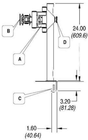
text_image
B A C D 24.00 (609.6) 3.20 (81.28) 1.60 (40.64)Model: MMT
Description
A. Adjustable Multi-Monitor assembly
B. Flat Panel Mounting brackets VESA 75/100
C. Removable desk clamp
D. Adjustable safety knob
E. Wall mount

text_image
B A E F 13.53 (343.66) 4.71 (119.63)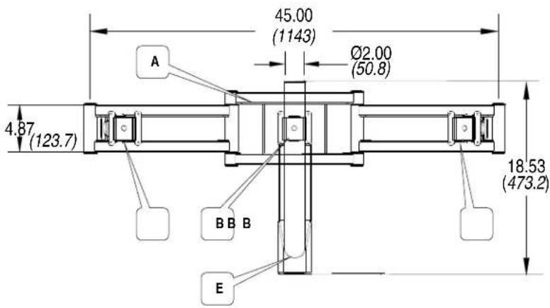
text_image
45.00 (1143) Ø2.00 (50.8) A 4.87 (123.7) BB B 18.53 (473.2) EModel: MMW
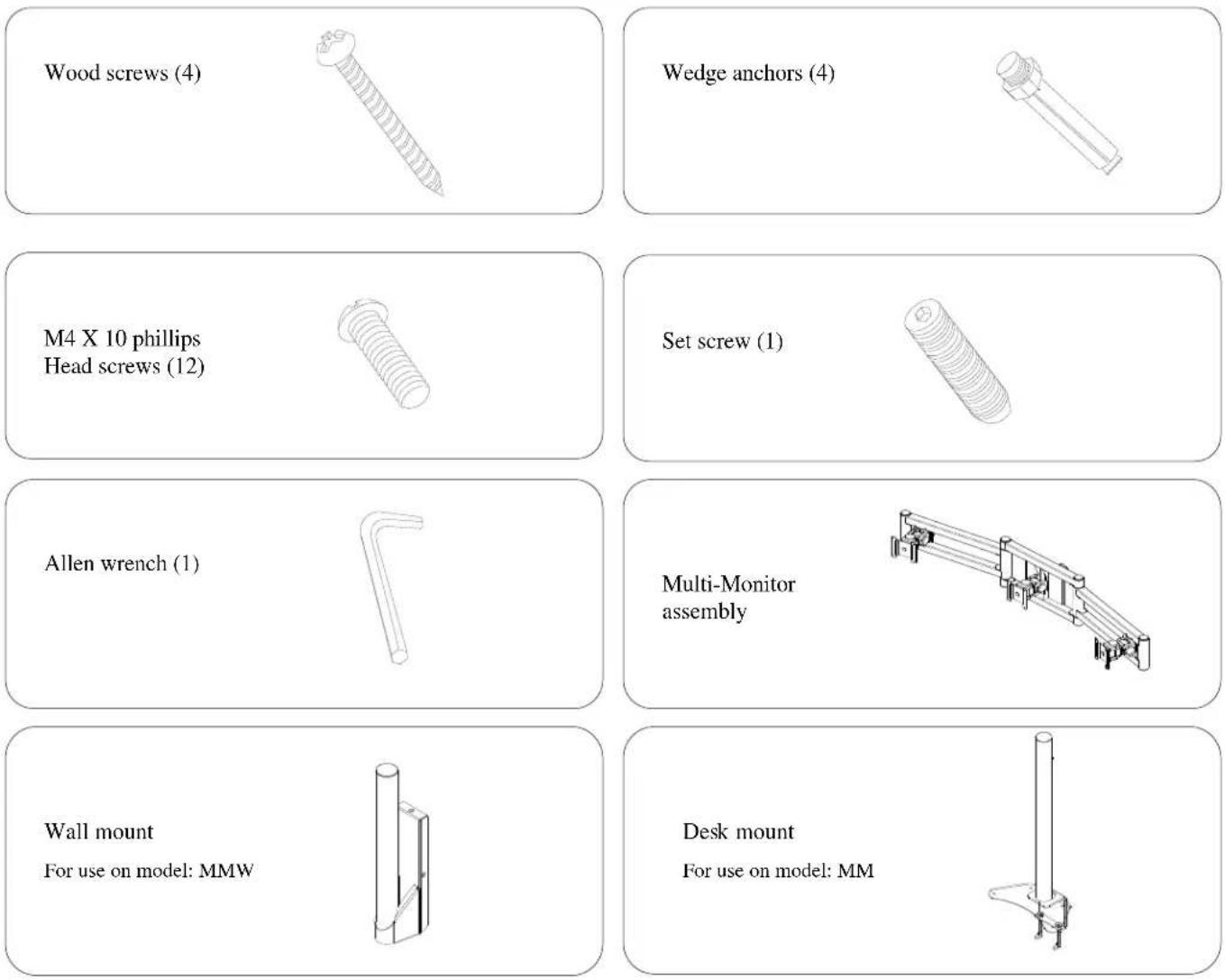
Parts list
NOTE: This wall mount is shipped with all proper installation hardware and components. Make sure that none of these parts are missing before beginning installation. If there are parts missing stop the installation and contact Premier Mounts.
Mounting the Multi-Monitor Mount to a desk or hard surface (model: MMT)
WARNING: Proper installation procedure by qualified personnel as outlined in the installation instructions must be adhered to. Failure to do so could result in serious personal injury and possible damage to the flat panel(s).

text_image
Figure 1 Monitor Multi- Monitor assembly (3) Mounting brackets Step 1 To secure the Multi-Monitor mount to a desk or hard surface position the post & clamp on the edge of the desk or hard surface. Then secure the Post by turning the two desk clamps until finger tight. See figure 1. Optional You may choose to secure your Multi-Monitor directly to your hard surface by drilling (4) four holes directly in the surface and then securing the unit with (4) commercially available wood screws. See option Wood screws (commercially available) Optional Removable desk clampStep 2
Using the (4) M4 X 10 Phillips screws (supplied) secure your monitor or monitors to the mounting brackets. See figure 2.

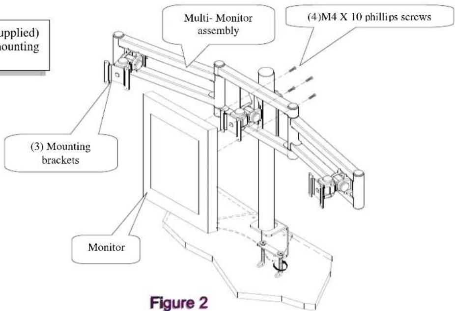
text_image
(4)M4 X 10 phillips screws Multi- Monitor assembly (3) Mounting brackets Monitor (3) Mounting mounting Figure 2Threading cables through cable access holes (model: MMT)

text_image
Figure 3 Upper cable access hole Cable Lower cable access hole Cable Adjustable desk clamp Step 3 To thread the cable or cables from the monitor through the post, start at the top access hole and gently pull cable out of the bottom access hole. See figure 3 MonitorMounting Multi-Monitor Mount to wall or concrete (model: MMW)
text_image
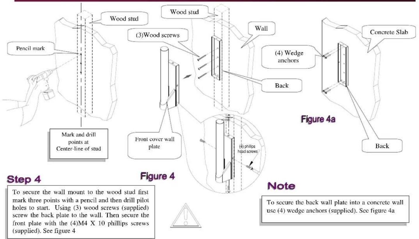
Pencil mark Mark and drill points at Center-line of stud Wood stud Wood stud (3)Wood screws Wall Back (4) Wedge anchors Concrete Slab Front cover wall plate Figure 4a Back Figure 4 Note To secure the wall mount to the wood stud first mark three points with a pencil and then drill pilot holes to start. Using (3) wood screws (supplied) screw the back plate to the wall. Then secure the front plate with the (4)M4 X 10 phillips screws (supplied). See figure 4 To secure the back wall plate into a concrete wall use (4) wedge anchors (supplied). See figure 4aMounting Multi-Monitor assembly to wall mount (model: MMW)
Figure 5
Step 5
Align the Multi-Monitor Assembly with the wall mount and slide the arm down around the wall mount post. To secure the arm to the wall mount, finger tighten the safety knob until the arm is secure. See figure 5

text_image
Multi-Monitor Adjustable safety knob Monitor (3)Mounting brackets Multi-Monitor Wall Wall mount Wood studAdjustments
text_image
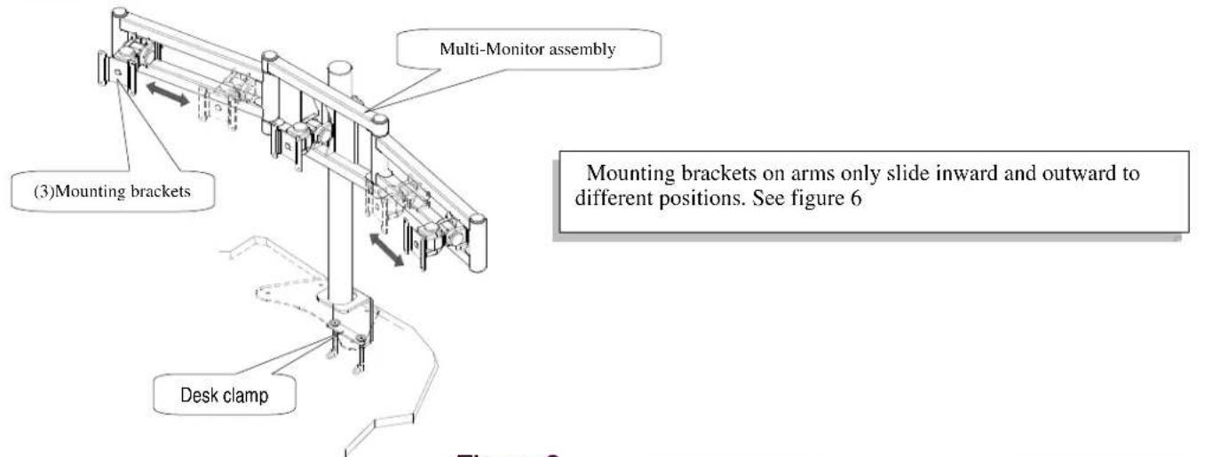
(3)Mounting brackets Multi-Monitor assembly Mounting brackets on arms only slide inward and outward to different positions. See figure 6 Desk clampFigure 6

text_image
Multi-Monitor assembly Adjusting metals Adjusts back and forth (both arms) Adjustable safety knob Desk clamp Figure 7Figure 7
text_image
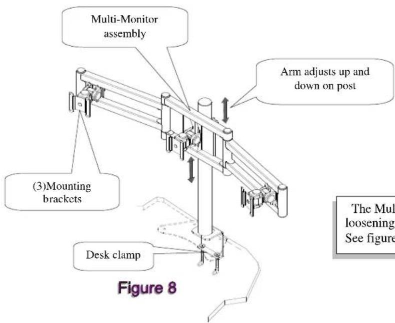
Multi-Monitor assembly Arm adjusts up and down on post (3)Mounting brackets Desk clamp Figure 8 The Multi loosening See figureThe Multi-Monitor assembly is adjusted up and down by loosening and tightening the adjustable safety knob.
See figure 8