DDW10CR2 - Security Camera Moog Videolarm - Free user manual and instructions
Find the device manual for free DDW10CR2 Moog Videolarm in PDF.

| Product Type | Security Camera |
| Brand | Moog Videolarm |
| Model | DDW10CR2 |
| Camera Type | Dome Camera |
| Resolution | 2 Megapixels (1920x1080) |
| Night Vision | IR LEDs up to 30 meters |
| Protection Rating | IP66 (Weatherproof) |
| Vandal Resistance | IK10 Rated |
| Power Supply | 12V DC or PoE (Power over Ethernet) |
| Dimensions | Diameter: 150 mm, Height: 110 mm |
| Weight | 1.2 kg |
| Operating Temperature | -40°C to +50°C |
| Horizontal Viewing Angle | 90 degrees |
| Video Compression | H.264 |
| Motion Detection | Yes, built-in |
| Maintenance | Clean with a soft, dry cloth; avoid abrasive cleaners |
| Safety | Professional installation recommended for optimal performance |
| Spare Parts & Repairability | Contact Moog Videolarm customer support for spare parts |
| General Information | Ideal for indoor and outdoor surveillance applications |
Frequently Asked Questions - DDW10CR2 Moog Videolarm
User questions about DDW10CR2 Moog Videolarm
0 question about this device. Answer the ones you know or ask your own.
Ask a new question about this device
Download the instructions for your Security Camera in PDF format for free! Find your manual DDW10CR2 - Moog Videolarm and take your electronic device back in hand. On this page are published all the documents necessary for the use of your device. DDW10CR2 by Moog Videolarm.
USER MANUAL DDW10CR2 Moog Videolarm
© 2009-2010, Moog Videolarm, Inc. All Rights Reserved
text_image
MOOG videolarm Product Information Dr. ©Moog Software 1.300.554.1124 www.videolarm.comDeputy Dome
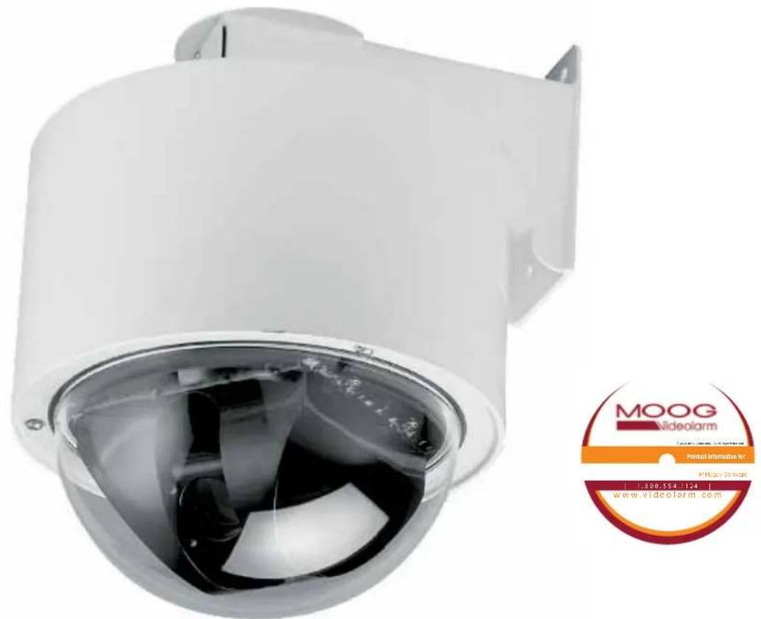
Bullet-Resistant Standard / Pressurized Dome
www.videolarm.com
Installation and Operation Instructions for the following models:
DDW10CR1 DeputyDome™ Series, 10-gauge Steel Bullet-Resistant Outdoor dome PTZ Camera System with 26x Day/Night Camera, onboard receiver /driver, 120VAC heater Tough enough to stop a 9mm bullet
PDDW10CR1 (Pressurized Version) DeputyDome™ Series, 10-gauge Steel Bullet-Resistant Outdoor dome PTZ Camera System with 26x Day/Night Camera, onboard receiver /driver, 120VAC heater Tough enough to stop a 9mm bullet
Before attempting to connect or operate this product, please read these instructions completely.

CERTIFIED
81-IN5210
10-07-2010
IMPORTANT SAFEGUARDS SAFETY PRECAUTIONS
1 Read these instructions.
2 Keep these instructions.
3 Heed all warnings
4 Follow all instructions.
5 Do not use this apparatus near water.
6 Clean only with damp cloth.
7 Do not block any of the ventilation openings. Install in accordance with the manufacturers instructions.
8 Cable Runs- All cable runs must be within permissible distance.
9 Mounting - This unit must be properly and securely mounted to a supporting structure capable of sustaining the weight of the unit.
Accordingly:
a. The installation should be made by a qualified installer.
b. The installation should be in compliance with local codes.
c. Care should be exercised to select suitable hardware to install the unit, taking into account both the composition of the mounting surface and the weight of the unit.
10 Do not install near any heat sources such as radiators, heat registers, stoves, or other apparatus (including amplifiers) that produce heat.
11 Do not defeat the safety purpose of the polarized or grounding-type plug. A polarized plug has two blades with one wider than the other. A grounding type plug has two blades and a third grounding prong. The wide blade or the third prong are provided for your safety. When the provided plug does not fill into your outlet, consult an electrician for replacement of the obsolete outlet.
12 Protect the power cord from being walked on or pinched particularly at plugs, convenience receptacles, and the point where they exit from the apparatus.
13 Only use attachment/ accessories specified by the manufacturer.
14 Use only with a cart, stand, tripod, bracket, or table specified by the manufacturer, or sold with the apparatus. When a cart is used, use caution when moving the cart/ apparatus combination to avoid injury from tip-over.
15 Unplug this apparatus during lighting storms or when unused for long periods of time.
16 Refer all servicing to qualified service personnel. Servicing is required when the apparatus has been damaged in any way, such as power-supply cord or plug is damaged, liquid has been spilled of objects have fallen into the apparatus, the apparatus has been exposed to rain or moisture, does not operate normally, or has been dropped.
Be sure to periodically examine the unit and the supporting structure to make sure that the integrity of the installation is intact. Failure to comply with the foregoing could result in the unit separating from the support structure and falling, with resultant damages or injury to anyone or anything struck by the falling unit.
UNPACKING
Unpack carefully. Electronic components can be damaged if improperly handled or dropped. If an item appears to have been damaged in shipment, replace it properly in its carton and notify the shipper.
Be sure to save:
1 The shipping carton and packaging material. They are the safest material in which to make future shipments of the equipment.
2 These Installation and Operating Instructions.
SERVICE
If technical support or service is needed, contact us at the following number:
TECHNICAL SUPPORT
AVAILABLE 24 HOURS
1-800-554-1124

CAUTION
RISK OF ELECTRIC SHOCK DO NOT OPEN

CAUTION: TO REDUCE THE RISK OF ELECTRIC SHOCK, DO NOT REMOVE COVER ( OR BACK). NO USER- SERVICE-ABLE PARTS INSIDE. REFER SEVICING TO QUALIFIED SERVICE PERSONNEL.
The lightning flash with an arrowhead symbol, within an equilateral triangle, is intended to alert the user to the presence of non-insulated "dangerous voltage" within the product's enclosure that may be of sufficient magnitude to constitute a risk to persons.
The exclamation point within an equilateral triangle is intended to alert the user to presence of important operating and maintenance (servicing) instructions in the literature accompanying the appliance.
PRODUCTCATEGORY PARTS LABOR
| All Enclosuresand Electronics | Five (5) Years | Five (5) Years | ||
| Pan/Tilts | Three (3) Years **6 months if used in autoscan /tour operation | Three (3) Years | **6 months if used in autoscan /tour operation | |
| Poles/PoleEvators | Three (3) Years | Three (3) Years | ||
| Warrior/Q-View/I.RIlluminators | Five (5) Years | Five (5) Years | ||
| SView Series | Five (5) Years*6 months if used in autoscan | Five (5) Years | **6 months if used in autoscan /tour operation | |
| Controllers | Five (5) Years /tour operation | Five (5) Years | ||
| PowerSupplies | Five (5) Years | Five (5) Years | ||
| AccessoryBrackets | Five (5) Years | Five (5) Years | ||
During the labor warranty period, to repair the Product, Purchaser will either return the defective product, freight prepaid, or deliver it to Videolarm Inc. Decatur GA. The Product to be repaired is to be returned in either its original carton or a similar package affording an equal degree of protection with a RMA# (Return Materials Authorization number) displayed on the outer box or packing slip. To obtain a RMA# you must contact our Technical Support Team at 800.554.1124 extension 101. Videolarm will return the repaired Product freight prepaid to Purchaser. Videolarm is not obligated to provide Purchaser with a substitute unit during the warranty period or at any time. After the applicable warranty period, Purchasemust pay all labor and/or parts charges.
The limited warranty stated in these product instructions is subject to all of the following terms and conditions:
TERMS AND CONDITIONS
-
NOTIFICATION OF CLAIMS: WARRANTY SERVICE: If Purchaser believes that the Product is defective in material or workmanship, then written notice with an explanation of the claim shall be given promptly by Purchaser to Videolarm but all claims for warranty service must be made within the warranty period. If after investigation Videolarm determines that the reported problem was not covered by the warranty, Purchaser shall pay Videolarm for the cost of investigating the problem at its then prevailing per incident billable rate. No repair or replacement of any Product or part thereof shall extend the warranty period as to the entire Product. The specific warranty on the repaired part only shall be in effect for a period of ninety (90) days following the repair or replacement of that part or the remaining period of the Product parts warranty, whichever is greater.
-
EXCLUSIVE REMEDY: ACCEPTANCE: Purchaser's exclusive remedy and Videolarm's sole obligation is to supply (or pay for) all labor necessary to repair any Product found to be defective within the warranty period and to supply, at no extra charge, new or rebuilt replacements for defective parts.
-
EXCEPTIONS TO LIMITED WARRANTY: Videolarm shall have no liability or obligation to Purchaser with respect to any Product requiring service during the warranty period which is subjected to any of the following: abuse, improper use: negligence, accident, lightning damage or other acts of God (i.e., hurricanes, earthquakes), modification, failure of the end-user to follow the directions outlined in the product instructions, failure of the end-user to follow the maintenance procedures recommended by the International Security Industry Organization, written in product instructions, or recommended in the service manual for the Product. Furthermore, Videolarm shall have no liability where a schedule is specified for regular replacement or maintenance or cleaning of certain parts (based on usage) and the end-user has failed to follow such schedule; attempted repair by non-qualified personnel; operation of the Product outside of the published environmental and electrical parameters, or if such Product's original identification (trademark, serial number) markings have been defaced, altered, or removed. Videolarm excludes from warranty coverage Products sold AS IS and/or WITH ALL FAULTS and excludes used Products which have not been sold by Videolarm to the Purchaser. All software and accompanying documentation furnished with, or as part of the Product is furnished "AS IS" (i.e., without any warranty of any kind), except where expressly provided otherwise in any documentation or license agreement furnished with the Product.
-
PROOF OF PURCHASE: The Purchaser's dated bill of sale must be retained as evidence of the date of purchase and to establish warranty eligibility. DISCLAIMER OF WARRANTY
EXCEPT FOR THE FOREGOING WARRANTIES, VIDEOLARM HEREBY DISCLAIMS AND EXCLUDES ALL OTHER WARRANTIES, EXPRESS OR IMPLIED, INCLUDING, BUT NOT LIMITED TO ANY AND/OR ALL IMPLIED WARRANTIES OF MERCHANTABILITY, FITNESS FOR A PARTICULAR PURPOSE AND/OR ANY WARRANTY WITH REGARD TO ANY CLAIM OF INFRINGEMENT THAT MAY BE PROVIDED IN SECTION 2-312(3) OF THE UNIFORM COMMERCIAL CODE AND/OR IN ANY OTHER COMPARABLE STATE STATUTE. VIDEOLARM HEREBY DISCLAIMS ANY REPRESENTATIONS OR WARRANTY THAT THE PRODUCT IS COMPATIBLE WITH ANY COMBINATION OF NON-VIDEOLARM PRODUCTS OR NON-VIDEOLARM RECOMMENDED PRODUCTS PURCHASER CHOOSES TO CONNECT TO PRODUCT.
LIMITATION OF LIABILITY
THE LIABILITY OF VIDEOLARM, IF ANY, AND PURCHASER'S SOLE AND EXCLUSIVE REMEDY FOR DAMAGES FOR ANY CLAIM OF ANY KIND WHATSOEVER, REGARDLESS OF THE LEGAL THEORY AND WHETHER ARISING IN TORT OR CONTRACT, SHALL NOT BE GREATER THAN THE ACTUAL PURCHASE PRICE OF THE PRODUCT WITH RESPECT TO WHICH SUCH CLAIM IS MADE. IN NO EVENT SHALL VIDEOLARM BE LIABLE TO PURCHASER FOR ANY SPECIAL, INDIRECT, INCIDENTAL, OR CONSEQUENTIAL DAMAGES OF ANY KIND INCLUDING, BUT NOT LIMITED TO, COMPENSATION, REIMBURSEMENT OR DAMAGES ON ACCOUNT OF THE LOSS OF PRESENT OR PROSPECTIVE PROFITS OR FOR ANY OTHER REASON WHATSOEVER.

Electrical Specifications
(Camera with hardwire pan/tilt)
Power Source & Power Consumption
(includes: heater, blower and camera)
DDW10CR
PDDW10CR

English
DDW10CR1 (N) 115 VAC, 90 vA, 0.8 Amps
DDW10CR2 (N) 24 VAC, (Class 2), 90 vA, 3.75Amps
(N) Network model
CAMERA SPECIFICATIONS
Resolution - 470 TVL - NTSC, 460TVL - PAL
Minimum Illumination - 1.0 1.0 Lux
Zoom Ratio - 26x, 3.5 -91mm optical, 321x digital
Format - 1/4"
White Balance - Auto
Electronic Shutter - 22 steps

Español
DDW10CR1 (N) 115 VAC, 90 vA, 0.8 amperios
DDW10CR2 (N) 24 VAC, (clase 2), 90 vA, 3.75Amps
natural_image
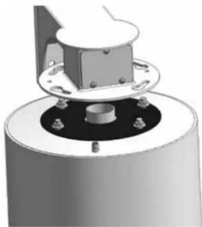
3D illustration of a mechanical assembly with layered components and a central cylindrical component (no text or symbols)1

natural_image
Mechanical component with a central hub and mounting holes, no visible text or symbolsRemove (2) tamper resistant with the security tool provided in the packet.
- Quite (2) a pisón resistente con la herramienta de la seguridad proporcionada en el paquete.
- Enlevez (2) le bourreur résistant avec l'outil de sécurité fourni dans le paquet.
- Entfernen Sie (2) den Besetzer, der mit dem Sicherheit Werkzeug beständig ist, das im Paket bereitgestellt wird.
- Remova (2) a calcadeira resistente com a ferramenta da segurança fornecida no pacote.
- Rimuova (2) il compressore resistente con l'attrezzo di sicurezza fornito nel pacchello.
2
natural_image
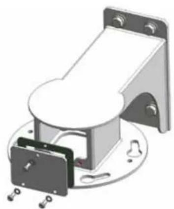
Mechanical assembly diagram showing a cylindrical component with mounting flanges and a central housing (no text or symbols)Loosen all flange nuts and turn the housing clockwise to remove the housing from the mount. The wall mount can now be attached to the wall.
- Afloje todas las tuercas del reborde y dé vuelta a la cubierta a la derecha para quitar la cubierta del montaje. El montaje de la pared se puede ahora unir a la pared.
- Détachez tous les écrous de bride et tournez le logement dans le sens des aiguilles d'une montre pour enlever le logement du bâti. Le bâti de mur peut maintenant être fixé au mur.
- Lösen Sie alle Flanschnüsse und drehen Sie das Gehäuse nach rechts, um das Gehäuse von der Einfassung zu entfemen. Die Wandeinfassung kann zur Wand jetzt angebracht werden.
- Afrouxe todas as porcas da flange e gire a carcaça no sentido horário para remover a carcaça da montagem. A montagem da parede pode agora ser unida à parede.
- Allenti tutti i dadi della flangia e giri l'alloggiamento in senso orario per rimuovere l'alloggiamento dal supporto. Il supporto della parete può ora essere fissato alla parete.
3
natural_image
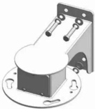
Mechanical component with mounting base and mounting bracket (no visible text or symbols)Bolt Housing securely to wall or pole.
- Cubierta de pemo con seguridad a la pared o al poste.
- Logement de boulon solidement au mur ou au poleau.
- Schraubbolzen-Gehäuse sicher zur Wand oder zum Pfosten.
- Carcaça de parafuso firmemente à parede ou ao pólo.
- Alloggiamento di bullone saldamente alla parete o al palo.
4
natural_image
3D rendering of a mechanical device with mounting bracket and housing (no text or symbols visible)After the wall mount is securely attached to the wall, remove the tamper resistant screws and take off the access plate.
- Después de que el montaje de la pared se una con seguridad a la pared, quite los tornillos resistentes del pisón y saque la placa del acceso.
- Après que le bâti de mur soit solidement fixé au mur, enlevez les vis résistantes de bourreur et enlevez le plat d'accès.
- Nachdem die Wandeinfassung sicher zur Wand angebracht ist, entfernen Sie die beständigen Schrauben des Besetzers und entfernen Sie die Zugang Platte.
- Depois que a montagem da parede é unida firmemente à parede, remova os parafusos resistentes da calcadeira e retire a placa do acesso.
- Dopo che il supporto della parete sia fissato saldamente alla parete, rimuova le viti resistenti del compressore e tolga la piastra di accesso.
5
flowchart
graph TD
    A["Top Source"] --> B["Stream 1"]
    A --> C["Stream 2"]
    A --> D["Stream 3"]
    A --> E["Stream 4"]
    B --> F["Output"]
    C --> F
    D --> F
    E --> F
A
B
C
D
E


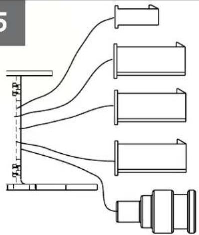
Wiring Chart Non-Pressurized Receiver Version
| A. Heater 24VAC 115VAC | |||
| 1) Red - Heater 1 | |||
| 2) N/C 2.4A .5A | |||
| 3) Red - Heater | |||
| B. Camera Power (58W) (58W) | |||
| 1) | Black - V2 | 1.5A | .3A |
| 2) Orange - V1 | |||
| C Lens ANALOG/ IP | (36W) | (36W) | |
| 1) | Blue - Alarm Input 1 | ||
| 2) | Violet - Alarm Input 2 | ||
| 3) | Gray - Alarm Input 3 | ||
| 4) | White - Alarm common | ||
| D. Pan/Tilt | |||
| 1) | Gray - RXA | ||
| 2) | Fink - N/C | ||
| 3) | Tan - TXA | ||
| 4) | Green - RXB | ||
| 5) | Brown - N/C | ||
| 6) | Blue - TXB | ||
| E. BNC 1(NETWORK IP) | |||
| F.Green Housing Ground (not shown) | |||
Wiring for DDW10CR
text_image
Video Shield TXA TXB NC NC RXA RXB Heater/Blower Heater/Blower A L B N M K C P U T J D R S H E F G Camera Power Camera Power Alarm Common Alarm In 2 Alarm In 3 Alarm In 1 NCWiring for Pressurized Receiver model (PDDW10CR2)
- Cableado para el modelo a presión del receptor (PDDW10CR2)
- Câblage pour le modèle pressurisé de récepteur (PDDW10CR2)
- Verdrahtung für unter Druck gesetztes Empfängermodell (PDDW10CR2)
- Fiação para o modelo pressurizado do receptor (PDDW10CR2)
• Collegamenti per il modello pressurizzato della ricevente (PDDW10CR2)
7
| Wire Gauge | ||||||||
| Total vA consumed | ^5_22 | ,7520 | 1,018 | 1,516 | 2,514 | 412 | 610 | MM ^2 AWG |
| 5.5 | ftm | 400121 | 600182 | 960292 | - | - | - | |
| 10 | 12036.5 | 18054.9 | 30091.4 | 480146 | 800243 | 1300396 | - | |
| 20 | 8627.1 | 14143.0 | 22568.6 | 358109 | 571174 | 905275 | 1440438 | |
| 30 | 6519.8 | 9027.4 | 13039.6 | 22568.6 | 350106 | 525160 | 830252 | |
| 40 | 4413.4 | 7021.3 | 11234.1 | 17954.6 | 28586.9 | 452138 | 720219 | |
| 50 | 3510.6 | 5617.1 | 9027.4 | 14343.6 | 22869.5 | 362110 | 576175 | |
| 60 | 299.4 | 4714.3 | 7522.9 | 11936.2 | 19057.9 | 30191.7 | 480146 | |
| 70 | 258.8 | 4012.2 | 6419.5 | 10231.1 | 16349.7 | 25878.6 | 411125 | |
| 80 | 317.6 | 3410.3 | 5516.8 | 8525.9 | 14042.7 | 21565.5 | 340103 | |
These are recommended maximum distances for 24VAC with a 10% voltage drop.
- Éstos se recomiendan las distancias máximas para 24VAC con una caída de voltaje del 10%.
- Ceux-ci sont recommandés des distances maximum pour 24VAC avec une chute de tension de 10%.
- Diese werden maximale Abstände für 24VAC mit einem 10% Spannungsabfall empfohlen.
- Estes são recomendados distâncias máximas para 24VAC com uma queda de tensão de 10%.
- Questi sono suggeriti distanze massime per 24VAC con una differenza de potenziale di 10%.
8
natural_image
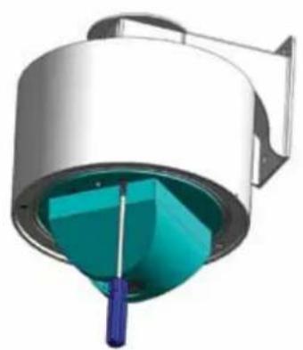
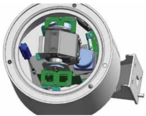
3D rendering of a cylindrical device with internal teal and blue components, no visible text or symbolsTo remove Pan/Tilt assembly remove the dome and liner
- Para eliminar Pan / Inclinación rmove montaje de la cúpula y de línea
- Pour supprimer Pan / Till rmove montage du dôme et doublure
- So entfernen Sie Pan / Tilt rmove Montage der Kuppel und Linienkonferenzen
- Para remover Pan / Tilt rmove montagem da cúpula e forro
• Per rimuovere Pan / Tilt remove assemblaggio e la cupola di linea
9
natural_image
3D cutaway view of a mechanical assembly showing internal components and housing (no text or symbols visible)Loosen captive bolt as shown
- Afloje el perno cautivo, como se muestra
• Desserrez pistolet comme le montre - Lösen Sie Bolzenschuss wie
- Afrouxe bolter cativeiro como mostrado
- Allentare bullone in cattività, come mostrato
10
text_image
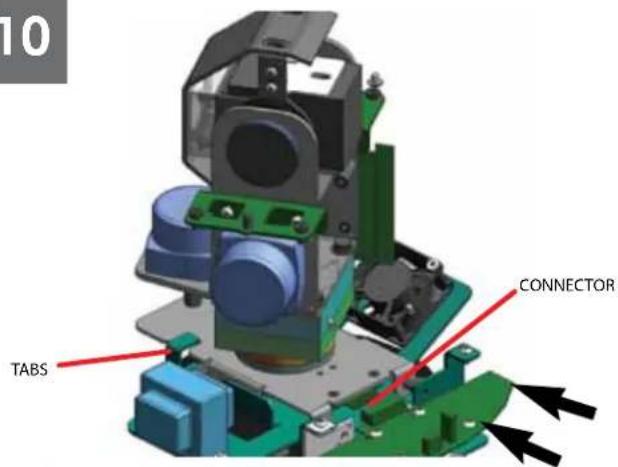
10 TABS CONNECTORSlide Pan/Tilt back till it aligns with the tabs
- Afloje el perno cautivo como shownSlide Pan / Inclinación atrás hasta que quede alineada con las pestañas
- Desserrez pistolet comme shownSlide Pan / Tilt revenir jusqu'à ce qu'il s'aligne avec les onglets
- Lösen Sie Bolzenschuss als shownSlide Pan / Tilt zurück, bis sie im Einklang mit den Regislerkarlen
- Afrouxe bolter cativeiro como shownSlide Pan / Tilt para trás até que allinha com os separadores
- Allentare bullone in cattività come shownSlide Pan / Tilt indietro sino a che non si allinea con le schede
natural_image
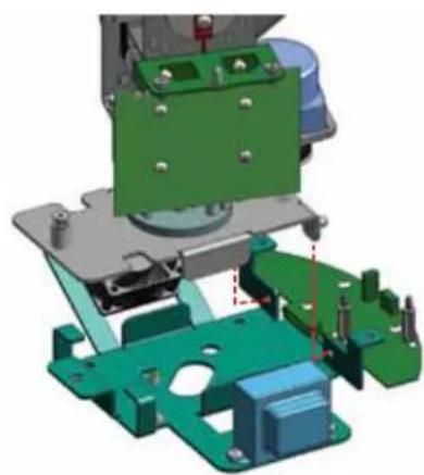
3D mechanical assembly diagram showing green and blue components with mounting holes (no text or symbols)Lift up on Pan/Tilt assembly to remove
- Levante de Pan / Inclinación de montaje para eliminar
- Soulevez le Pan / Tilt d'assemblage pour enlever
- Heben Sie auf Pan / Tilt Montage zu entfernen
• Levante ontário Pan / Tilt montagem para remover - Sollevare il Pan / Tilt assemblaggio di rimuovere
12
text_image
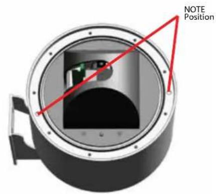
NOTE PositionTo attach dome inserts most align properly with housing
- Para adjuntar cúpula alinear correctamente la mayoría de las inserciones de la vivienda
- Pour joindre la plupart des inserts dôme aligner correctement avec le logement
- So hängen die meisten Einsätze Kuppel Angleichung richtig mit Gehäuse
- Para anexar cúpula insere mais alinhar corretamente com habitação
- Per allegare cupola inserti allineare correttamente con la maggior parte degli alloggi
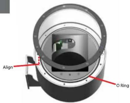
text_image
Align O RingAlign insert and install dome
• Alinear insertar e instalar cúpula
• Alignez et installez insérer dôme
- Richten Sie einfügen und installieren Kuppel
- Alinhar inserir e instalar cúpula
- Allineare inserire e installare cupola
14
text_image
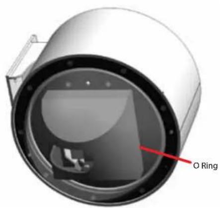
O RingIf Lanyard attaches to both trim ring and the outside of the housing
- Si Lanyard concede a ambos y el anillo exterior de la vivienda
- Si Lanyard attache à la fois l'asslette et le ring extérieur de l'habitation
- Wenn Lanyard misst sowohl trim Ring und die außerhalb des Gehäuses
- Se colhedor atribui a ambos os anéis e os remates de fora da habitação
- Se Lanyard attribuisce ad entrambi i trim anello e l'esterno del corpo
15
natural_image
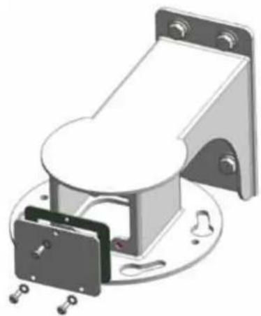
3D rendering of a mechanical assembly with mounting bracket and housing (no text or symbols visible)To pressurize unit, remove wall mount access cover
- Para presionar a la unidad, extraíga el montaje en pared cubierta de acceso
- De faire pression sur l'unité, retirer l'accès couvrir murale
- Um Druck-Einheit, entfernen Wandhalterung Abdeckung
- Para pressionar unidade, remova parede montar acesso cobrir
- Per pressurizzare unità, rimuovere il montaggio a parete coperchio di accesso
16
text_image
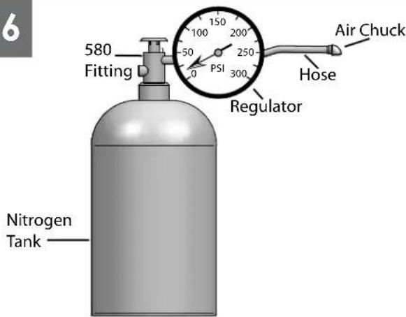
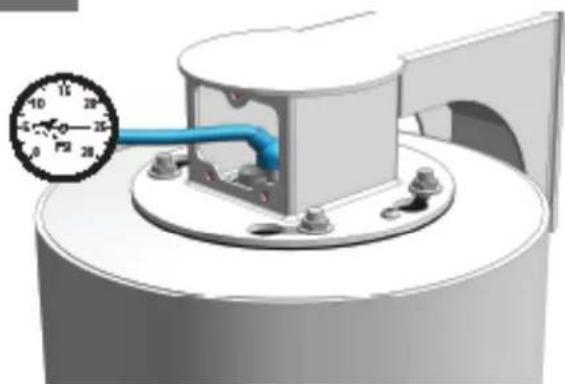
6 580 Fitting 100 200 PSI 250 300 Regulator Air Chuck Hose Nitrogen TankWhen pressurizing unit be sure to set the guage or regulator from 10-20psi (.7-1.4bar).
- Al presurizar la unidad sea seguro fijar la medida o el regulador de 10-20psi (7-1.4bar).
- En pressurisant l'unité soyez sûr de placer la jauge ou le régulateur de 10-20psi (7-1.4bar).
- Wenn Sie Maßeinheit unter Druck setzen, seien Sie sicher, das Eichmaß oder den Regler von 10-20psi (7-1.4bar) einzustellen.
- Ao pressurizar a unidade seja certo ajustar o guage ou o regulador de 10-20psi (7-1.4bar).
- Nel pressurizzare l'unità sia sicuro regolare il misuratore o il regolatore da 10-20psi (7-1.4bar).

natural_image
3D rendering of a mechanical assembly with a blue pipe inserted into a circular housing (no text or symbols visible)Place the air chuck on the tank valve and begin filling until pressure relief valve opens.
- Coloque la tirada del aire en la válvula del tanque y comience a llenar hasta que la válvula de descarga de presión se abre.
- Placez le mandrin d'air sur la valve de réservoir et commencez à remplir jusqu'à ce que la valve de décompression s'ouvre.
- Setzen Sie die Luftklemme auf das Behälterventil und fangen Sie an zu füllen, bis Druckablaßventil sich öffnet.
- Coloque o mandril do ar na válvula do tanque e comece a encher-se até que a válvula de escape de pressão abra.
- Disponga il mandrino dell'aria sulla valvola del carro armato e cominci a riempirsi fino a che la valvola limitatrice della pressione non si apra.
18
natural_image
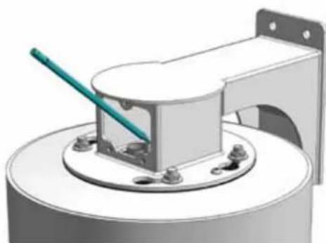
3D rendering of a mechanical assembly with a green tool inserted into a cylindrical component (no text or symbols visible)Open the relief valve. Drain all air from the housing and repeat twice to remove all moisture.
- Abra la válvula de descarga. Drene todo el aire de la cubierta y de la repetición dos veces para quitar toda la humedad.
- Ouvrez la soupape de sécurité. Évacuez tout l'air le logement et la répétition deux fois pour enlever toute l'humidité.
- Öffnen Sie das Sicherheitsventil. Lassen Sie alle Luft aus dem Gehäuse und der Wiederholung zweimal ab, um alle Feuchtigkeit zu entfernen.
- Abra a válvula de escape. Drene todo o ar da carcaça e do repeat duas vezes para remover toda a umidade.
- Apra la valvola di sfiato. Vuoti due volte tutta l'aria dall'alloggiamento e dalla ripetizione per rimuovere tutta l'umidità.
19
natural_image
3D rendering of a mechanical component with a blue pipe and pressure gauge (no text or symbols)After purging check the housing pressure. It should be around 5psi (.34bar).
- Después de purgor el cheque la presión de la cubierta. Debe estar orededor de 5psi [34bar].
- Après la purge du contrôle la pression de logement. Elle devrait être autour de 5psi (34bar).
- Nochdem Überprüfung der Gehäusedruck bereinigt worden ist. Sie sollte um 5psi [34bor] sein.
- Após ter removido a venificação a pressão da carcoça. Deve ser em tomo de 5psi (34bar).
- Dopo leminosione del inceppo del controla la pressione dell'atteggiamento. Dowrebbe essere intamo a 5psi (S4bar).
20
CHANGING SETTINGS FOR RECEIVER / DRIVER UNITS
text_image
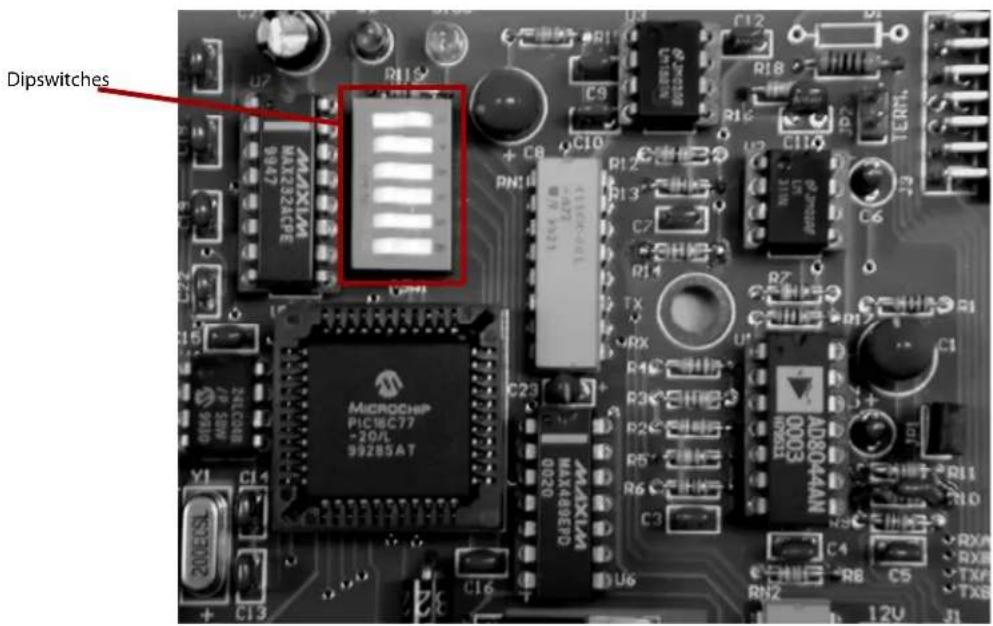
Dipswitches MAX1A MAX2A24CE 9927 + C8 C10 PN11 R12 R13 C7 R14 TX RX R7 C15 CN50B 7P 5W Y1 C14 C23 MAX489EFD 0020 AD8044AN 0003 R11 R10 C4 RN2 C5 TXF TXS C6 TERTLDIPSWITCHES
The dipswitches serve a dual purpose. First, they control the address of the pan/tilt when operated via RS485. Second, they control the alarm and display functions for the pan/tilt. Address changes are made using the dip switches located on the PC board.
21
CHART 1 - RECEIVER/DRIVER PAN/TILT ADDRESSES
| Address | SW1 | SW2 | SW3 | SW4 | SW5 | SW6 |
| 1 | Off | On | On | On | On | On |
| 2 | On | Off | On | On | On | On |
| 3 | Off | Off | On | On | On | On |
| 4 | On | On | Off | On | On | On |
| 5 | Off | On | Off | On | On | On |
| 6 | On | Off | Off | On | On | On |
| 7 | Off | Off | Off | On | On | On |
| 8 | On | On | On | Off | On | On |
| 9 | Off | On | On | Off | On | On |
| 10 | On | Off | On | Off | On | On |
| 11 | Off | Off | On | Off | On | On |
| 12 | On | On | Off | Off | On | On |
| 13 | Off | On | Off | Off | On | On |
| 14 | On | Off | Off | Off | On | On |
| 15 | Off | Off | Off | Off | On | On |
| 16 | On | On | On | On | Off | On |
| 17 | Off | On | On | On | Off | On |
| 18 | On | Off | On | On | Off | On |
| Address | SW1 | SW2 | SW3 | SW4 | SW5 | SW6 |
| 19 | Off | Off | On | On | Off | On |
| 20 | On | On | Off | On | Off | On |
| 21 | Off | On | Off | On | Off | On |
| 22 | On | Off | Off | On | Off | On |
| 23 | Off | Off | Off | On | Off | On |
| 24 | On | On | On | Off | Off | On |
| 25 | Off | On | On | Off | Off | On |
| 26 | On | Off | On | Off | Off | On |
| 27 | Off | Off | On | Off | Off | On |
| 28 | On | On | Off | Off | Off | On |
| 29 | Off | On | Off | Off | Off | On |
| 30 | On | Off | Off | Off | Off | On |
| 31 | Off | Off | Off | Off | Off | On |
UNIT ADDRESSES FOR 485 CONTROL
The dipswitches come factory preset with switch 6 in the on position, indicating the address mode. The default address for the pan/tilt on receiver/driver versions of the DeputyDome™ is preset at the factory as "1." If more than one unit is being used with 485 control it will be necessary to change the address for each additional unit.
To change the address, power down the unit, remove the pan/tilt from the housing, and set the address using the dipswitch settings shown in Chart 1 in the next column. Replace the unit and power up.
22
UNIT PARAMETERS
Alarm sense, camera on-screen display and baud rate can all be controlled by the dipswitches. The alarm sense can be set to accept either contact closures (NO) or contact openings (NC) as the alarm condition. The camera on-screen display will show icons on the monitor when zoom, focus, and iris are used. Factory presets are contact closures for the alarm sense, "off" for the camera on-screen display, and 9600 baud. To change parameters, power down the unit, remove the pan/tilt from the housing, and set the desired parameter using switches 1 and 2 as directed in chart 2 below. Replace the unit and power up. In UTC mode there is nothing further to do. However, if you're operating in 485 mode you must reset the address AFTER POWERING BACK UP following the instructions above.
CHART 2 - PARAMETER DIP SWITCH SETTINGS
| Switch | Settings |
| SW6 | Address data - On (Closed) |
| SW5 | A4 |
| SW4 | A3 |
| SW3 | A2 |
| SW2 | A1 |
| SW1 | A0 |
| Switch | Settings |
| SW6 | Parameters - Off (open) |
| SW5 | On Off- No Operation - Erase EEPROM |
| SW4 | On Off |
| SW3 | BAUD RATE: On-9600 Off-4800 |
| SW2 | ALARM: On - NC Off - NO |
| SW1 | DISPLAY: On - Display on Off - Display off |
NOTE:
Erasing the EEPROM will override the other switch settings. If the EEPROM is erased, power the unit off, set the switches to the desired baudrate, alarm position and display mode, with SW4 and SW5 ON and SW6 OFF, then power the unit on again. Finally, power the unit off, set the address and make sure that SW6 is ON, power the unit on and begin normal operation.
23
CONTROL FUNCTIONS
Zoom, Focus and Iris
Using the manual focus commands leaves the unit in manual focus mode. Using the manual iris commands will leave the unit in manual iris mode as well. Zooming the camera will restore the camera to auto-focus and auto-iris. Goto preset 89 will also restore auto-focus and auto-iris.
Protocols
The DeputyDome is commanded electrically via RS-485 4-wire protocol. The transmitter is disabled when not in use to allow multiple camera systems to be tied to the same response pair.
Control protocols supported are VL-422 (detailed in the Appendix) and Pelco-P and Pelco-D. The DeputyDome will automatically sense which protocol is being used and respond to it. Baud rates of 9600 (factory default) and 4800 are available. See the Unit Parameters section above for instructions on setting the baud rate.
Presets
The DeputyDome has 64 presets that can be used individually or as part of an autotour. To program a preset, set the pan, tilt, zoom, focus and backlight compensation settings to the desired value. Issue the command to store/program the preset number using an appropriate controller. (See the Appendix) When the Goto Preset number command is given, the system will move to the stored pan, tilt, zoom, focus and backlight settings at the highest available speed.
| Preset Number | Function |
| 79 Record/Run | Pattern 2 |
| 80 Record/Run | Pattern 1 |
| 81 Stop Recording Pattern (1 or 2) | |
| 84 Reset the Camera System | |
| 85 Backlight Compensation On | |
| 86 Backlight Compensation Off | |
| 87 Night Mode | |
| 88 Day Mode | |
| 89 Auto Iris / Auto Day/Night | |
| 99 Clear All Presets | |
24
Autotour
The Autotour function causes the camera to automatically go, in sequence, to each preset that has been programmed into the PTZ. The dwell time at each preset position can be individually set to be from 0 to 99 seconds. See the Menu Driven Settings section to learn how to set dwell time. The
Autotour will continue until a pan or tilt command is given. If the unit loses power while in Autotour, Autotour will be resumed when power is restored.
Pattern
The DeputyDome allows recording of two patterns with each pattern being up to 2 minutes in length. This is a separate feature from Autotour.
To record a pattern:
- If the camera is in autotour, use the joystick to stop it.
- Clear all customized presets such as preset 1, 2, 3 etc. (Note: Once the pattern has been recorded, the presets can be set again)
- Set preset 80 (8->0->#->Set) to begin recording pattern 1 (or set preset 79 to begin recording pattern 2)
- Use joystick to move the camera (the movement is recorded)
- Set preset 81 (8->1->#->Set) to stop recording (for Pattern 1 or 2)
To run a pattern:
- If the camera is in autotour, use the joystick to stop it.
- Go to preset 80 (8->0->Set) to run Pattern 1 (or go to preset 79 to run Pattern 2)
To stop a pattern:
Move the joystick
Note: 1. Pattern and Autotour are different processes. Make sure to use joystick to stop one before initiating another.
- In case there is a power outage, the camera would go to Home position after the power is recovered.
- To erase a recorded pattern, just record a new pattern and the old one will be automatically erased.
Additional Functions
Additional functions are available using Goto Preset above the normal preset range. The table below describes these functions.
Replacement Parts List
DDW10CR / PDDW10CR
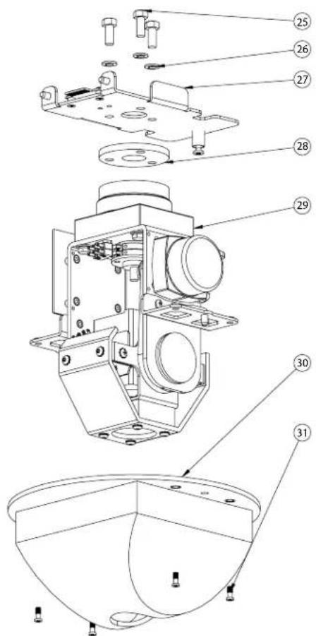
text_image
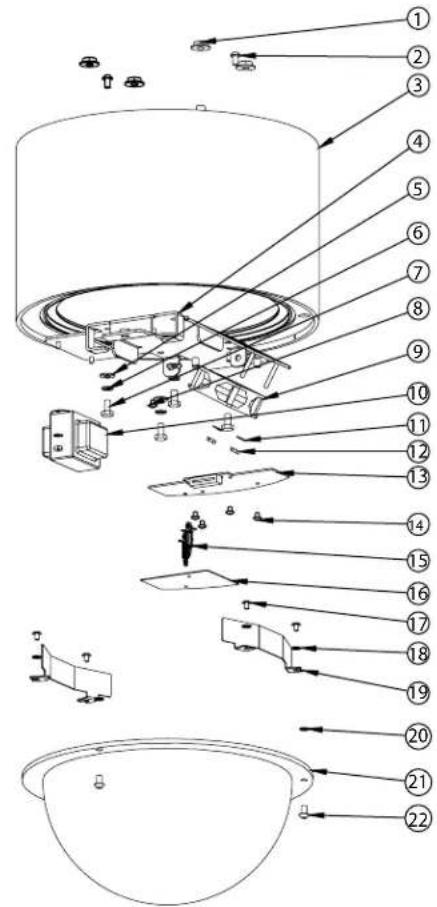
Exploded view diagram of a mechanical assembly with numbered parts and directional arrows indicating assembly or movement.Part Number Description Qty.
| 1 | 90-NTFL01 3/8-16 Flange Nut 4 | ||
| 2 | 90-BTSEC06 1/4-20X 1/2" Security screw SS 2 | ||
| 3 | 50-VL1428 DDWC10 housing body 1 | ||
| 4 | 30-VL1405 DDWC10 accs mounting bracket 1 | ||
| 5 | 92-WSFL01 1/4 Flat Washer SS 4 | ||
| 6 | 92-WSSL01 1/4 Split Lockwasher SS 4 | ||
| 7 | 90-BTHH32 1/4-20 X 1/2" Hex head bolt SS 4 | ||
| 8 | 90-BTRP31 8-32X 3/8" Grounding screw 1 | ||
| 9 | 71-BLEH24 Blower, 24VDC 60MM 1 | ||
| 10 | 70-WPTRAN/P2 240/120V: 1.5A 24V Transformer | 1 | |
| 11 | 92-WSTH02 #8 Star washer | 8 | |
| 12 | 91-NTHH06 8-32 Hex nut SS | 4 | |
| 13 | 76-DD01PCB DDWC10 Housing PCB 1 | ||
| 14 | 90-BTRP19 8-32 X 3/8 Round head screw SS 4 | ||
| 16 | 30-VL1522 DDW10C Electrical Shield 1 | ||
| 17 | 90-BTRP20 #10-32 X 3/8" pan head screw SS 4 | ||
| 18 | 92-WSTH04 #10 Star washer | 3 | |
| 19 | DDWC10 Heater | 2 | |
| 20 | 96-RSORNG 1/4 O-ring | 3 | |
| 21 | RCDWW10 Clear dome for DeputyDomeTM 1 | ||
| 22 | 90-BTSEC04 1/4-20 x 3/8" security screws 3 | ||
| 25 | 90-BTHH33 5/16-18 X 3/4 Hex head bolt SS 3 | ||
| 26 | 92-WSSL02 5/16 Split Lockwasher SS 3 | ||
| 27 | 30-VL1408 DDWC10 P/T Quick release bkt 1 | ||
| 28 | 96-MPDDW Pan/tilt mounting pad | 1 | |
| 29 | DDWC10 pan/tilt | 1 | |
| 30 | 30-VL1313 DDWC10 rotating liner 1 | ||
| 31 | 95-FSC04 10-32X1/2" Captive screw | 4 | |
| 35 | DDWC10 bearing assembly | 1 | |
| 36 | 60-4011 18 tooth 1/5" belt drive pulley | 1 | |
| 37 | 60-4015 55 tooth 1/5" timinig belt, pan | 1 | |
| 38 | 60-4013 36 tooth 1/5" belt drive pulley, DD pan | 1 | |
| 39 | 90-BTHH37 8-32 X 1/2" Trimmed hex head SS 8 | ||
| 40 | 92-WSTH02 #8 Star washer | 5 | |
| 41 | 30-VL1411 DDWC10 P/T bracket 1 | ||
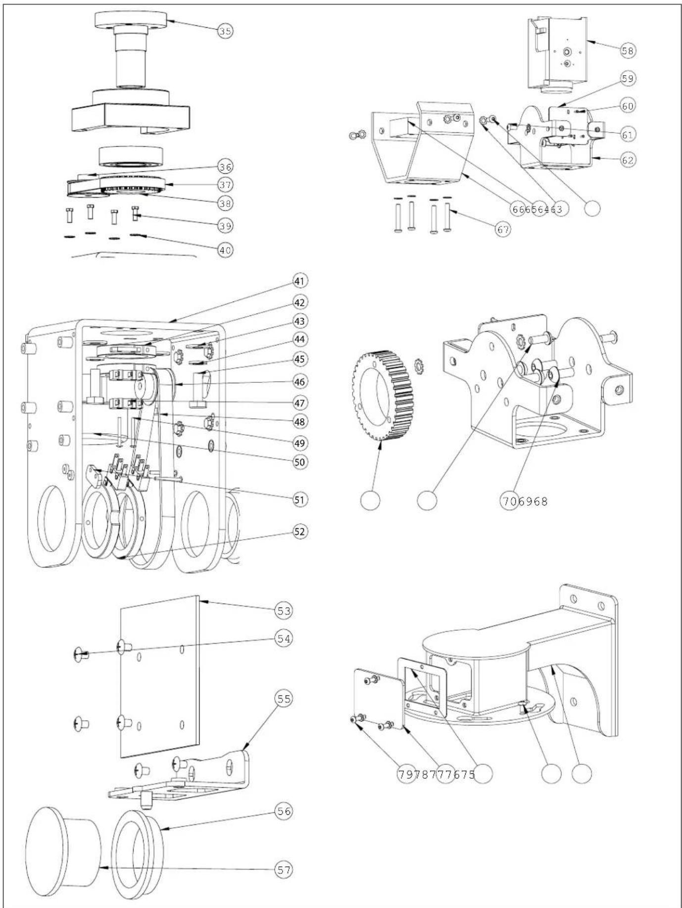
text_image
Technical diagram of a mechanical assembly with numbered parts for identificationPart Number
Description Qty.
| 42 | 60-1414 | DDWC10 pan limits collars | 2 | |
| 43 | 92-WSFL01 1/4 Flat washer SS | 4 | ||
| 44 | 92-WSSL01 1/4 Split lockwasher SS | 4 | ||
| 45 | 90-BTHH27 1/4-20X3/4" Hex head bolt SS | 4 | ||
| 46 | 60-4010 | 14 tooth 1/5" belt drive pulley | 1 | |
| 47 | 60-3012 | OMRON SS-5GL2Tr.par | 4 | |
| 48 | 60-4012 | 36 tooth 1/5" belt drive pulley, DD tilt | 1 | |
| 49 | 90-BTSR19 2-56 X | 75" Pan head screw | 2 | |
| 50 | 60-3010 | Hurst 2RPM pan motor SA-SP | 2 | |
| 51 | 30-VL1509 Limit switch spacer | 2 | ||
| 52 | 60-1420 | DDWC10 tilt limits collars | 2 | |
| 53 | 76-DD03PCB DDWC10 pan/tilt PC board | 1 | ||
| 54 | 90-BTRP19 8-32 X | 3/8 round head screw SS | 5 | |
| 55 | 30-VL1417 DDWC | 10 liner arms | 2 | |
| 56 | 60-1412 | DDWC10 tilt bushings | 2 | |
| 57 | 60-1421 | DDWC10 tilt shafts | 2 | |
| 58 | 73-CAMTR01 | 1/3"CCD AF 16X ZOOM 12VDC NTSC | 1 | |
| 59 | 30-VL1415 DDWC | 10 Camera Bracket | 1 | |
| 60 | 90-BTSM01 1.5mm X 6mm Sheet metal screw SS | 3 | ||
| 61 | 90-BTRP20 #10-32 X | 3/8" PN HD PHIL SS | 6 | |
| 62 | 30-VL1419 DDWC | 10 tilt bracket | 1 | |
| 63 | 90-BTBS04 10-32x | 1/2" Button Head screw SS | 7 | |
| 64 | 92-WSTH04 | #10 Star washer | 13 | |
| 65 | 27-WDDW10 | DDWC10 window | 1 | |
| 66 | 30-VL1418 DDWC | 10 tilt liner | 1 | |
| 67 | 90-BTBS05 10-32x | 1 1/4" Button Head screw SS | 4 | |
| 68 | 60-4014 | 62 tooth 1/5" timing belt, tilt | 1 | |
| 69 | 90-BTBS04 10-32x | 1/2" Button Head screw SS | 7 | |
| 70 | 90-BTBS08 1/4-20X | 1/2" Button Head screw SS | 4 | |
| 75 | 50-VL1430 DDWC | 10 wall mount | 1 | |
| 76 | 90-BTSEC06 1/4-20X | 1/2" Security screw SS | 2 | |
| 77 | 96-GKDDWM | Access cover gasket | 1 | |
| 78 | 30-VL1431 DDWC | 10 Wall Mount access cover | 1 | |
| 79 | 90-BTSEC05 10-32X | 1/2" Security screw | 3 | |
| NS | 96-GKDDW01 | Housing gasket | 1 | |
| NS | 96-RSORG8 | Dome O-ring | 1 | |
VL-422 Communication Protocol (DeputyDome)
1 Message Format
Data is transmitted at 9600 baud, 1 start bit, 1 stop bit, 8 data bits (lsb first), no parity. The general format for messages sent to the DeputyDome and for inquiry response messages sent by the DeputyDome is shown below:
| BYTE DATA DESCRIPTION | ||
| 1 F8H Sync character | ||
| 2 Address in hex Camera | address (01H – DFH) | |
| 3 to N-1 Command Data | All command characters are 8-bit characters; most are ASCII characters. | |
| N | Terminator and Checksum | 80H - 8FH Most significant bit is always 1. Least significant (LS) nibble is XOR of all previous bytes (LS nibble only) except for the leading character F8H. |
The acknowledge message sent from the DeputyDome shall consist of a single hexadecimal 06 character. The negative acknowledge message shall consist of a single hexadecimal 15 character. Characters enclosed in quotes represent ASCII characters and numbers followed by an "H" are hexadecimal numbers.
2 Message Sequence
Each message transaction is initiated by the controller. The DeputyDome shall respond to each successfully received message with an ACK message no sooner than 1ms. and no later than 20ms. after the last byte of the message has been received. If the message is not understood by the DeputyDome, a NACK message will be sent.
If an inquiry message is successfully received from the host, the DeputyDome shall respond with the ACK message as previously described and the inquiry response shall then be transmitted no sooner than 1ms. and no later than 100ms. after the transmission of the ACK.
3 Command Messages
These commands control the basic motion of the pan/tilt platform and the lens movement of the camera system. Byte number 1 is the start of message F8, byte number 2 is the device address (default = 01), and byte number five is the message terminator byte.
3.1 Motion Command Messages
| FUNCTION Byte #3 Byte #4 DESCRIPTION | |||
| PAN LEFT "P" "L" Move at default speed. | |||
| PAN RIGHT | "P" | "R" | Move at default speed. |
| PAN STOP | "P" | "S" | |
| TILT UP | "T" | "U" | Move at default speed. |
| TILT DOWN | "T" | "D" | Move at default speed. |
| TILT STOP | "T" | "S" | |
| ZOOM IN "Z" "I" Zoom In (Telephoto) | |||
| ZOOM OUT | "Z" | "O" | Zoom Out (Wide angle) |
| ZOOM STOP | "Z" | "S" | |
| FOCUS NEAR | "F" | "N" | |
| FOCUS FAR | "F" | "F" | |
| FOCUS STOP | "F" | "S" | |
| IRIS OPEN | "I" | "O" | |
| IRIS CLOSE | "I" | "C" | |
| IRIS STOP | "I" | "S" | |
| PAN LEFT AT SPEED "x" | "I" | "O" - "?" | Pan left at speed index 0-15. ("I" is lower-case "L".) |
| PAN RIGHT AT SPEED "x" | "I" | "O" - "?" | Pan right at speed index 0-15. |
| TILT UP AT SPEED "x" | "u" | "O" - "?" | Tilt up at speed index 0-15. |
| TILT DOWN AT SPEED "x" | "d" | "O" - "?" | Tilt down at speed index 0-15. |
3.2 Preset Command Messages
These commands control the position presets and some of the operational parameters of the pan/tilt platform. Byte number 1 is the start of message "F8", byte number 2 is the device address (default = 01), and byte number five is the message terminator byte. Note that preset 63 is reserved for another function; this preset number is used in the commands "P""?" and "H""?".
| FUNCTION Byte #3 Byte #4 DESCRIPTION | |||
| GOTO PRESET POSITIONPresets 1 – 64 | “H” 01H – 40H | Goto preset position. | |
| SAVE PRESET POSITIONPresets 1 – 64 | “P” 01H – 40H | Store preset position. | |
| CLEAR PRESETPresets 1 – 63 | “K” 01H – 40H | Clear preset position from memory. | |
| CLEAR ALL PRESETS “P” “C” Clears all presets from memory | |||
| AUTO TOUR ON “L” “A” | Enables the auto tour. Any pan left or pan right will turn off the auto tour. | ||
| PRESET STATUS REQUEST “H” “?” | Requests current preset status | ||
3.3 Preset Response Message
| FUNCTION Byte #3 Byte #4 DESCRIPTION | |||
| PRESET INQUIRY RESPONSE | “H” | 01H – 40H“A”“I”“E” | Currently at preset 01H – 40H.“A” Active, going to preset.“I” Inactive, not at preset.“E” Error, unable to go to preset. |
3.4 Address Assignment Message\*\*
This six-byte command sets the address of the dome. The address is in hexadecimal and is contained in bytes 4 and 5. If the address is set to FFH, then the unit derives its address from the dipswitch. Byte number 1 is the start of message "F8", byte number 2 is the device address (default = 01), and byte number six is the message terminator byte.
| FUNCTION | Byte #3 | Byte #4 | Byte #5 | DESCRIPTION |
| ASSIGN UNIT ADDRESS | “A” | 30H - 3FH 30H - 3FH | Set unit address. Byte 4 contains the ms nibble of address and Byte 5 contains Is nibble of address. |
Example: Set address of unit 1 to 53 (decimal) = 35H :
F8H 01H 41H 33H 35H 86H
3.5 Goto Position Message
This command causes the platform to go to an absolute position based on the motor encoders. The "GOTO POSITION" command is longer than the preceding command messages and is shown in its complete form in the following table:
| BYTE | DATA | DESCRIPTION |
| 1 | F8H | Sync character |
| 2 | Address in hex | Camera address (01H - FFH) |
| 3 | “p” | Lower case “p” |
| 4 | A2 (MS nibble) 30H - 3FH | Position data is 30H ored with data nibbleA11, A10, A09, A08 of azimuth data. |
| 5 | A130H - 3FH | Position data is 30H ored with data nibbleA07, A06, A05, A04 of azimuth data. |
| 6 | A0 (LS nibble)30H - 3FH | Position data is 30H ored with data nibbleA03, A02, A01, A00 of azimuth data. |
| 7 | E2 (MS nibble)30H - 3FH | Position data is 30H ored with data nibbleE11, E10, E09, E08 of elevation data. |
| 8 | E130H - 3FH | Position data is 30H ored with data nibbleE07, E06, E05, E04 of elevation data. |
| 9 | E0 (LS nibble)30H - 3FH | Position data is 30H ored with data nibbleE03, E02, E01, E00 of elevation data. |
| 10 | Terminator and Checksum | 80H - 8FH Most significant bit is always 1. Least significant (LS) nibble is the XOR of all previous bytes (LS nibble only) except for leading autobaud character F8H. |
Notes on "Goto position" command:
Pan position has a range of 0 – 2880. This represents the range of 0 to 360 degrees in steps of .15 degree. A pan position of 000 represents the home position.
Tilt position has a range of 0 to 950. This represents a range of 0 to 95 degrees in steps of .10 degree. Position 0 is the maximum down position and position 950 is the maximum up (horizontal) position. Home position is at 450.
3.6 Position Feedback
This command causes the platform to report the current pan and tilt position based on the motor encoders. Byte number 1 is the start of message F8H, byte number 2 is the device address (default = 01), and byte number five is the message terminator byte.
| FUNCTION Byte #3 Byte #4 DESCRIPTION | |||
| REQUEST POSITION "P" | “?” Get position. | ASCII character upper case "p" followed by the “?” character. | |
The response to this command is shown in the table below:
| BYTE DATA DESCRIPTION | ||
| 1 F8H Sync character | ||
| 2 Address in hex Camera | address (01H - DFH) | |
| 3 "P" Upper case "P" | ||
| 4 | A2 (MS nibble) 30H- 3FH | Position data is 30H ored with data nibbleA11, A10, A09, A08 of azimuth data. |
| 5 | A130H - 3FH | Position data is 30H ored with data nibbleA07, A06, A05, A04 of azimuth data. |
| 6 | A0 (LS nibble)30H - 3FH | Position data is 30H ored with data nibbleA03, A02, A01, A00 of azimuth data. |
| 7 | E2 (MS nibble)30H - 3FH | Position data is 30H ored with data nibbleE11, E10, E09, E08 of elevation data. |
| 8 | E130H - 3FH | Position data is 30H ored with data nibbleE07, E06, E05, E04 of elevation data. |
| 9 | E0 (LS nibble)30H -3FH | Position data is 30H ored with data nibbleE03, E02, E01, E00 of elevation data. |
| 10 | Terminator and Checksum | 80H - 8FH Most significant nibble is always 8. Least significant (LS) nibble is the XOR of all previous bytes (LS nibble only) except for leading autobaud character F8H. |
3.7 GoTo Lens Position Commands
This command causes the lens to go to an absolute position based on the motor encoders. The "GOTO LENS POSITION" is shown in its complete form in the following table:
| BYTE DATA DESCRIPTION | ||
| 1 F8H Sync character | ||
| 2 Address in hex Camera address (01H - DFH) | ||
| 3 "v" Lower case "v" | ||
| 4 | Z2 (MS nibble) 30H- 3FH | Position data is 30H ored with data nibbleZ11, Z10, Z09, Z08 of zoom lens position data. |
| 5 | Z130H - 3FH | Position data is 30H ored with data nibbleZ07, Z06, Z05, Z04 of zoom lens position data. |
| 6 | Z0 (LS nibble)30H - 3FH | Position data is 30H ored with data nibbleZ03, Z02, Z01, Z00 of zoom lens position data. |
| 7 | F2 (MS nibble)30H - 3FH | Position data is 30H ored with data nibbleF11, F10, F09, F08 of lens focus position data. |
| 8 | F130H - 3FH | Position data is 30H ored with data nibbleF07, F06, F05, F04 of lens focus position data. |
| 9 | F0 (LS nibble)30H - 3FH | Position data is 30H ored with data nibbleF03, F02, F01, F00 of lens focus position data. |
| 10 | Terminator and Checksum | 80H - 8FH Most significant nibble is always 8. Least significant (LS) nibble is the XOR of all previous bytes (LS nibble only) except for leading autobaud character F8H. |
3.8 Lens Position Feedback Commands
| FUNCTION Byte #3 Byte #4 DESCRIPTION | |||
| REQUEST POSITION "V" | “?” Get position. | ASCII character "V" followed by the "?" character. | |
The response to this command is shown in the table below:
| BYTE DATA DESCRIPTION | ||
| 1 F8H Sync character | ||
| 2 Address in hex Camera | address (01H - DFH) | |
| 3 "V" Upper case "V" | ||
| 4 | Z2 (MS nibble) 30H- 3FH | Position data is 30H ored with data nibbleZ11, Z10, Z09, Z08 of zoom lens position data. |
| 5 | Z130H - 3FH | Position data is 30H ored with data nibbleZ07, Z06, Z05, Z04 of zoom lens position data. |
| 6 | Z0 (LS nibble)30H - 3FH | Position data is 30H ored with data nibbleZ03, Z02, Z01, Z00 of zoom lens position data. |
| 7 | F2 (MS nibble)30H - 3FH | Position data is 30H ored with data nibbleF11, F10, F09, F08 of focus data. |
| 8 | F130H - 3FH | Position data is 30H ored with data nibbleF07, F06, F05, F04 of focus data. |
| 9 | F0 (LS nibble)30H - 3FH | Position data is 30H ored with data nibbleF03, F02, F01, F00 of focus data. |
| 10 | Terminator and Checksum | 80H - 8FH Most significant nibble is always 8. Least significant (LS) nibble is the XOR of all previous bytes (LS nibble only) except for leading autobaud character F8H. |
3.9 Latch Commands
The camera commands control parameters of camera operation. All the Camera commands generate a Latch Status response message.
| FUNCTION Byte #3 Byte #4 DESCRIPTION | |||
| MANUAL IRIS TOGGLE | "L" "M" Toggles | iris operation between auto iris and manual iris. | |
| CAMERA POWER TOGGLE "L" "P" Toggles camera | operation on and off. | ||
| LENS SPEED TOGGLE "L" "L" Toggles between high speed and low speed zoom | |||
| TOGGLE AUX1 & AUTO WHITE BALANCE | "L" "1" | Toggles AUX1 output. Also puts camera into auto white balance. | |
| INCREASE BLUE GAIN** "B" "1" Increase Blue gain in camera. | |||
| INCREASE RED GAIN** "B" "2" Increase Red gain in camera. | |||
| STOP COLOR GAIN** | "B" "0" Stop Red/Blue increase. | ||
| PRESET STATUS REQUEST | "L" "?" | Requests | current camera status |
3.10 Latch Status Response Message
| BYTE | DATA | DESCRIPTION |
| 1 | F8H | Smyc character |
| 2 | Address in hex | Camera address (01H - DFH) |
| 3 | "L" | Upper case "L" |
| 4 30H - 38H | bit0 (lsb) Auto Iris; 0 = auto, 1 = manualbit1 Camera power; 0 = off, 1 = onbit2 Lens speed; 0 = slow; 1 = fastbit3 Comm. error; 0 = no, 1 = yesbit4 - bit7 = 0011. | |
| 5 “A” Upper case “A” | ||
| 6 30H - 31H bit0 (lsb) aux output; 0 = off, 1 = on | ||
| 7 | Terminator and Checksum | 80H - 8FH Most significant nibble is always 8. Least significant (LS) nibble is the XOR of all previous bytes (LS nibble only) except for leading autobaud character F8H. |
3.11 Sensor Feedback Commands\*\*
| FUNCTION Byte #3 Byte #4 DESCRIPTION | |||
| REQUEST SENSOR DATA "S" "?" Get pressure and temperature data. | |||
The response to this command is shown in the table below:
| BYTE DATA DESCRIPTION | ||
| 1 F8H Autobaud character | ||
| 2 Address in hex Camera | address (01H - DFH) | |
| 3 "S" Upper case "S" | ||
| 4 | P1 (MS nibble) 30H - 3FH | Pressure data is 30H ored with data nibbleP07, P06, P05, P04 of pressure data. |
| 5 | P0 (LS nibble)30H - 3FH | Pressure data is 30H ored with data nibbleP03, P02, P01, P00 of pressure data. |
| 6 | T1 (MS nibble)30H - 3FH | Temperature data is 30H ored with data nibbleT07, T06, T05, T04 of temperature data. |
| 7 | T0 (LS nibble)30H - 3FH | Temperature data is 30H ored with data nibbleT03, T02, T01, T00 of temperature data. |
| 8 | Terminator and Checksum | 80H - 8FH Most significant nibble is always 8. Least significant (LS) nibble is the XOR of all previous bytes (LS nibble only) except for leading autobaud character F8H. |
** Not supported on DeputyDome
Product Registration/Warranty
Thank you for choosing Videolarm. We value your patronage and are solely committed to providing you with only the highest quality products available with unmatched customer service levels that are second-to-none in the security industry.
Should a problem arise, rest assure that Videolarm stands behind its products by offering some of the most impressive warranty plans available: 3 Years on all Housings, Poles, Power Supplies, and Accessories and 5 Years on all camera systems (SView, QView, Warriors), and InfraRed Illuminators.

5
Register Your Products
Option 1: Online Option 2: Mail-In
Take a few moments and validate your purchase with our Online Product Registration Form
at www.videolarm.com/productregistration.jsp
or complete and mail-in the bottom portion of this flyer.
Register your recent Videolarm purchases and benefit from the following:
- Simple and Trouble-Free RMA process
- Added into customer database to receive product updates / news
- Eliminate the need to archive original purchase documents:
Receipts, Purchase Orders, etc...

Cut at the dotted Line
Place in envelope, affix stamp and mail to:
Videolarm ATTN: Warranty
2525 Park Central Ave.
Decatur, GA 30035
Main Contact Info
First Name: Last Name:
Professional Title: Company:
Address 1: Address 2:
City: State / Province/Country:
Zip / Postal Code: Phone Number: E-mail Address:
Product Information
Please Circle One: Business
Personal
Name & Location of Company / Store where Purchased:
(City, State, Country)
Videolarm Product ID Product Description
Serial #
(Available only for Camera Systems, IR Illuminators, Wireless Devices)
PO#