
KTG330S - Range hood Chief - Free user manual and instructions
Find the device manual for free KTG330S Chief in PDF.


| Product Type | Free-standing pole mount for multiple displays |
| Brand | Chief |
| Model | KTG330S (part of KTG-Series) |
| Mounting Options | Grommet mount (through flat surface) or base mount |
| Display Compatibility | Multiple displays; supports VESA patterns up to 200x200 mm (screws M4 x 12/20/30 mm) |
| Maximum Weight Capacity | Not specified; typical for KTG-Series up to 125 lbs per display (estimate) |
| Pole Height | Available in 14", 28", or 42" (model dependent) |
| Adjustments | Horizontal slide, pitch (+/-15°), roll, and 360° rotation |
| Materials | Steel, aluminum, nylon spacers |
| Cable Management | Integrated cable clips on array rail and cable management sheath (8" included) |
| Installation Tools Required | Drill (1/2" bit), Phillips screwdriver, 3/4" wrench, hex keys (3/32", 5/32", 7/32") |
| Included Accessories | Pole, pipe cap, array rail, Centris head, clamps, screws, grommets, hex keys |
| Dimensions (KTG330S approx) | Pole: 1.75" OD; Array rail: 34" (dual) or 42" (triple) depending on configuration |
| Weight (empty) | Not specified; estimated 15-20 lbs (6.8-9 kg) |
| Warranty | Not specified; typically 5-10 years for Chief mounts |
Frequently Asked Questions - KTG330S Chief
User questions about KTG330S Chief
0 question about this device. Answer the ones you know or ask your own.
Ask a new question about this device
Download the instructions for your Range hood in PDF format for free! Find your manual KTG330S - Chief and take your electronic device back in hand. On this page are published all the documents necessary for the use of your device. KTG330S by Chief.
USER MANUAL KTG330S Chief
INSTALLATION INSTRUCTIONS
Horizontal And Vertical Table Stands and Accessories
Model: KTG-Series
The KTG-Series is a free standing, pole mount solution for multiple displays.

TOOLS REQUIRED FOR INSTALLATION
- Drill and 1/2" drill bit (larger if mounting through a flat surface and using cable management)
• Phillips Head Screw Driver - 3/4" Wrench
• 3/32" Hex Key (provided) - 5/32" Hex Key (provided)
- 7/32" Hex Key (provided)
INSPECT MOUNT BEFORE ASSEMBLY
Carefully inspect components for shipping damage. If damage is apparent, call your carrier claims agent and do not continue with installation until the carrier has reviewed the damage.(see Figure 1)
Table 1: Parts
| QUANTITY By MODEL | |||||||||
| ITEM | DESCRIPTION 220 225 230 320 325 330 440 445 | ||||||||
| 10 CENTRIS HEAD ASSEMBLY, Pole Mount 2 | |||||||||
| 20 ARRAY ASSEMBLY, Dual, 27" 1 1 2 | |||||||||
| ARRAY ASSEMBLY, Dual, 34" 2 | |||||||||
| 30 ARRAY ASSEMBLY, Triple, 42" 1 1 | |||||||||
| ARRAY ASSEMBLY, Triple, 54" 1 | |||||||||
| 40 | PIPE CAP, 1.75 OD | 1 | 1 | 1 | 1 | 1 | 1 | 1 | 1 |
| 50 | POLE, Freestand, 14" | 1 | 1 | 1 | 1 | ||||
| 60 POLE, Freestand, 28" | 1 | 1 1 1 | |||||||
| 70* | POLE, Freestand, 42" | ||||||||
| 80 | SHEATH, Cable Management, 8" | 1 | 1 | 2 | 1 | 1 | 2 | 2 | 2 |
| 90 | N/A | N/A | N/A | N/A | N/A | N/A | N/A | N/A | |
| 100 | SCREW, Cable Management Grommet Mounting, 3/8-16 x 6" | 1 | 1 | 1 | 1 | 1 | 1 | 1 | 1 |
| 110 | GROMMET, Mounting | 2 | 2 | 2 | 2 | 2 | 2 | 2 | 2 |
| 120 | KEY, Hex, 5/32" | 1 | 1 | 1 | 1 | 2 | 1 | 1 | 1 |
| 130 | KEY, Hex, 3/16" | 1 | 1 | 1 | 1 | 2 | 1 | 1 | 1 |
| 140 | KEY, Hex, 7/32" | 1 | |||||||
| 160** | SCREW, Phillips Pan Head, M4 x 12mm | 8 | 8 | 8 | 12 | 12 | 24 | 16 | 16 |
| 170** | SCREW, Phillips Pan Head, M4 x 20mm | 8 | 8 | 8 | 12 | 12 | 24 | 16 | 16 |
| 180** | SCREW, Phillips Pan Head, M4 x 30mm | 8 | 8 | 8 | 12 | 12 | 24 | 16 | 16 |
| 190** | SPACER, Nylon, 3/8" (used with item 170) | 8 | 8 | 8 | 12 | 12 | 24 | 16 | 16 |
| 200** | SPACER, Nylon, 3/4" (used with item 180) | 8 | 8 | 8 | 12 | 12 | 24 | 16 | 16 |
| 210 | CLAMP, Front, Pole Mount | 2 | |||||||
| 220 | CLAMP, Rear, Pole Mount | 2 | |||||||
| 230 | SCREW, Button Head Cap, 1/4-20 x 1 1/4" | 6 | 6 | ||||||
| 240 | CLAMP, Back, Array mounting | 1 | 1 | 1 | 1 | 2 | 2 | 2 | |
| 250 | WASHER, Flat, 1/4" | 2 | 2 | 2 | 2 | 4 | 4 | 4 | |
| 260 | SCREW, Button Head Cap, 1/4-20 x 3/4" | 2 | 2 | 2 | 2 | 4 | 4 | 4 | |
| * Indicates an available optional accessory not included with above models. For additional information pertaining to available accessories contact a Chief Customer Service represenatative or visit us at www.chiefmfg.com.** Quantity varies depending upon the number of displays being installed. | |||||||||

Figure 1: Parts
ASSEMBLY AND INSTALLATION
Grommet Mount Installation
To install on a flat surface:
- Locate desired point on surface where mount is to be installed. (see Figure 2)
- Drill a 1/2" dia. hole through surface.
- Slide one 3/8-16 x 6" HHCS (100) upward through lower grommet (110), through hole in surface and through upper grommet (110).
- Place pole (50, 60, 70) onto upper grommet (110) aligning threaded hole in pole bottom with threaded end of 3/8-16 x 6" HHCS (100).
- Thread 3/8-16 x 6" HHCS (100) into pole bottom (50, 60, 70) and tighten to secure pole and grommets (110) to surface.
- Add pipe cap (40) to top of pole.
- Mount Centris head assembly or array assembly to rail following the instructions outlined in KTG-220, 320, And 440 Assembly section of this document.
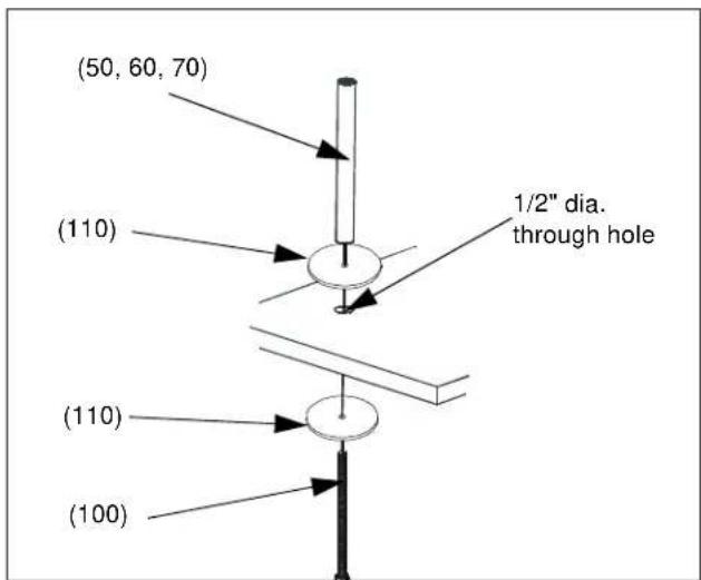
Figure 2: Grommet installation
Mount Assembly
KTG-230 Assembly
- Place front pole clamp with Centris Head (210) against pole in approximate mounting location.
- Place three BHCS (230) into rear pole clamp (220) and place against pole aligning with front pole clamp (210). (see Figure 3)
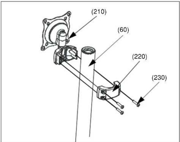
Figure 3: Mount Centris Head with Pole Clamp
NOTE: Equally tighten screws (230) against front pole mount (210) and the rear pole clamp (220). (see Figure 4)

Figure 4: Tightening clamp to mount
10. Secure rear pole clamp (220) to front pole mount (210) and pole by tightening three BHCS (230) using 5/32" hex key (120). (see Figure 3)
KTG-220, 320, And 440 Assembly
To assemble the KTG-220, 320, and 440:
NOTE: If mount is being installed without the base through a flat surface, proceed to Grommet Mount Installation.
-
Assemble pole (50) to base (40) using one 3/8-16 x 1" FHCS (90). (see Figure 2)
-
Assemble pole clamp back (240) to pole mount front using two FW (250) and two BHCS (260) using a 5/32" hex key. (see Figure 5)
-
Secure pole mount back (240) to pole mount front and pole by tightening two BHCS (260) using a 5/32" hex key.

Figure 5: Assemble Array Rail to Pole
Display Installation
Attach Centris Head to Flush Mount Display
CAUTION!
CAUTION: If display uses a screw size other than those included in the kit, DO NOT use the screws provided. Using the wrong screws could result in damage to your monitor.
- Install two M4 x 12mm Phillips pan head screws (160) into two upper mounting holes in display back. (see Figure 6)
NOTE: DO NOT fully tighten at this time.
-
Hang display on Centris head. (see Figure 7)
-
Install bottom two M4 x 12mm Phillips pan head screws (160) through Centris head mounting holes and into lower mounting holes in display back.
-
Tighten ALL four M4 x 12mm Phillips pan head screws (160). (see Figure 8)
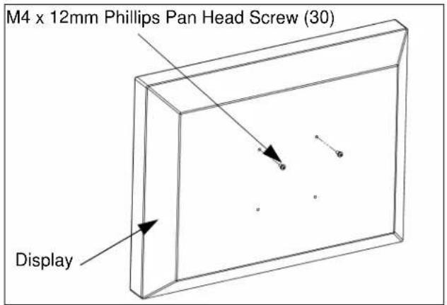
Figure 6: Prepare Display

Figure 7: Hang Display
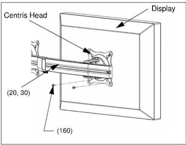
Figure 8: Secure Display to Centris Bracket
Attach Centris Head to Recessed Mount Display
NOTE: Refer to Table 1 to select the applicable screw and spacer combination.
-
Uninstall end lock using the 5/32" hex key (120). (see Figure 9)
-
Remove Centris head from array rail (20, 30).
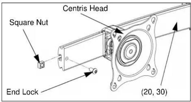
Figure 9: Remove End Lock(s)
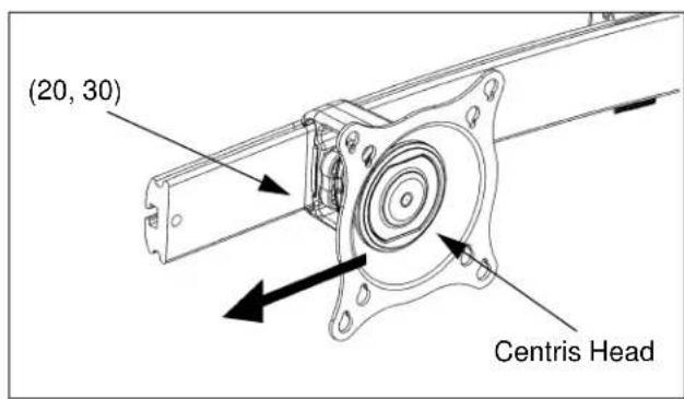
Figure 10: Slide Centris Bracket off Array Rail
-
Place display face down on a clean dry surface.
-
Place four 3/8" or 3/4" nylon spacers (190 or 200) over four mounting holes in display back (see Figure 11).
-
Align Centris head mounting holes with four nylon spacers (see Figure 11).
-
Secure Centris head to display using four M4 x 20mm Phillips pan head screws (170), or four M4 x 30mm Phillips pan head screws (180) (see Figure 11).
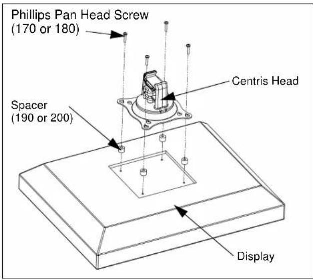
Figure 11: Mount Centris Bracket to Display
- Slide display with Centris bracket onto array rail (20, 30) (see Figure 12).
NOTE: Repeat previous steps for each additional display.
- Reinstall end locks into mounting rail using the 5/32" hex key (120) (see Figure 13).

Figure 12: Mount Display with Centris Bracket to Array Rail

Figure 13: Reinstall End Lock(s)
ADJUSTMENTS
Display Adjustment
The KTG Series mount allows horizontal, pitch, and rotational adjustment of each display.
The KTG Series mount also allows a full 360 deg. of display rotation with a maximum pitch range of 15^ up and 15^ down.
Display Horizontal Position Adjustment
To adjust display horizontal position:
- Loosen Centris bracket rear adjustment knob (see Figure 14).
- Slide Centris bracket with display left or right until properly positioned on array rail.
- Tighten Centris bracket rear adjustment knob.

Figure 14: Display Horizontal Adjustment
Display Pitch and Roll Adjustment
To adjust display pitch or roll position:
- Loosen Centris bracket front adjustment knob. (see Figure 15)
- Tilt display up or down, or adjust display roll left or right until properly positioned.
- Tighten Centris bracket front adjustment knob.

Figure 15: Display Pitch and Roll Adjustment
CABLE MANAGEMENT
The KTG Series mount includes cable management features used to properly route and secure display cables.
To use the cable management features:
- Connect cables to display.
- Route cables through cable clips on array rail.
- Route cables down pole and away from mount and secure to pole using sheath (80).

Figure 16: Cable Management


- INSTALLATION INSTRUCTIONS
- Horizontal And Vertical Table Stands and Accessories
- Model: KTG-Series
- TOOLS REQUIRED FOR INSTALLATION
- INSPECT MOUNT BEFORE ASSEMBLY
- ASSEMBLY AND INSTALLATION
- Grommet Mount Installation
- Mount Assembly
- KTG-230 Assembly
- KTG-220, 320, And 440 Assembly
- Display Installation
- Attach Centris Head to Flush Mount Display
- CAUTION!
- Attach Centris Head to Recessed Mount Display
- ADJUSTMENTS
- Display Adjustment
- Display Horizontal Position Adjustment
- Display Pitch and Roll Adjustment
- CABLE MANAGEMENT
Brand : Chief
Model : KTG330S
Category : Range hood