
MHZ2320BJ - Hard Drive TOSHIBA - Free user manual and instructions
Find the device manual for free MHZ2320BJ TOSHIBA in PDF.

| Product Type | 2.5-inch Hard Disk Drive |
| Brand | Toshiba |
| Model | MHZ2320BJ |
| Interface | SATA (Serial ATA) compliant with Revision 2.5/2.6 |
| Form Factor | 2.5-inch |
| Mounting Screw | M3, tightening torque 0.49 N·m (5 kgf·cm) |
| Mounting Orientation | Any direction |
| Ambient Temperature | As per Section 1.4; DE cover temperature must not exceed 60°C |
| Breather Hole | Must not be blocked; locate as per Figure 3.3 |
| Handling Precautions | Use ESD wrist strap and mat; do not drop, stack, or press cover |
| Service Area | As shown in Figure 3.5 |
| Connector | SATA interface with power and signal segments |
| Connection Force | Do not exceed 10 kgf when mating connectors |
| Latch Operation | Release latch before connecting/removing cable |
| Surface Temperature Measurement Points | See Figure 3.4 and Table 3.1 |
| DE Cover Temperature Limit | 60°C maximum |
| Recommended Driver | Low impact electric driver |
| ESD Protection | Required |
| Shock Absorbing Mat | Recommended |
| Repairability | Not user-serviceable; contact professional service |
| Spare Parts | Not available as spare; contact Toshiba |
| Maintenance | Ensure airflow; keep breather hole free |
| Safety | Avoid strong magnetic fields; do not press cover |
| Additional Notes | Refer to Fujitsu 2.5-inch HDD Integration Guidance for mounting details |
Frequently Asked Questions - MHZ2320BJ TOSHIBA
User questions about MHZ2320BJ TOSHIBA
0 question about this device. Answer the ones you know or ask your own.
Ask a new question about this device
Download the instructions for your Hard Drive in PDF format for free! Find your manual MHZ2320BJ - TOSHIBA and take your electronic device back in hand. On this page are published all the documents necessary for the use of your device. MHZ2320BJ by TOSHIBA.
USER MANUAL MHZ2320BJ TOSHIBA
CHAPTER 3 Installation Conditions
3.1 Dimensions
3.2 Mounting
3.3 Connections with Host System
This chapter gives the external dimensions, installation conditions, surface temperature conditions, cable connections, and switch settings of the hard disk drives.
3.1 Dimensions
Figure 3.1 illustrates the dimensions of the disk drive. All dimensions are in mm.
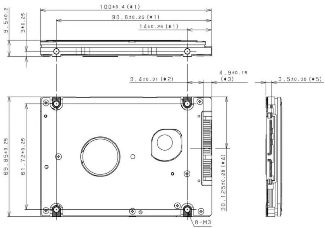
*1 The PCA and connectors are not included in these dimensions.
*2 Dimension from the center of the user tap to the base of the connector pins
*3 Length of the connector pins
*4 Dimension from the outer edge of the user tap to the center of the connector pins
*5 Dimension from the outer edge of the user tap to the innermost edge of the connector pins
Figure 3.1 Dimensions
3.2 Mounting
For information on mounting, see the "FUJITSU 2.5-INCH HDD INTEGRATION GUIDANCE (C141-E144)."
(1) Orientation
The disk drives can be mounted in any direction.
(2) Frame
The MR head bias of the HDD disk enclosure (DE) is zero. The mounting frame is connected to Signal Ground (SG).
IMPORTANT
Use M3 screw for the mounting screw and the screw length should satisfy the specification in Figure 3.2.
The tightening torque must be 0.49N·m (5kgf·cm).
When attaching the HDD to the system frame, do not allow the system frame to touch parts (cover and base) other than parts to which the HDD is attached.
(3) Limitation of mounting
Note) These dimensions are recommended values; if it is not possible to satisfy them, contact us.
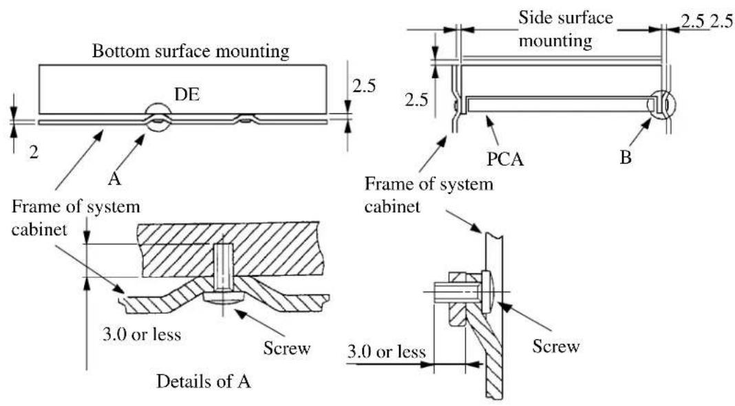
Figure 3.2 Mounting frame structure
IMPORTANT
Because of breather hole mounted to the HDD, do not allow this to close during mounting.
Locating of breather hole is shown as Figure 3.3.
For breather hole of Figure 3.3, at least, do not allow its around 3 to block.
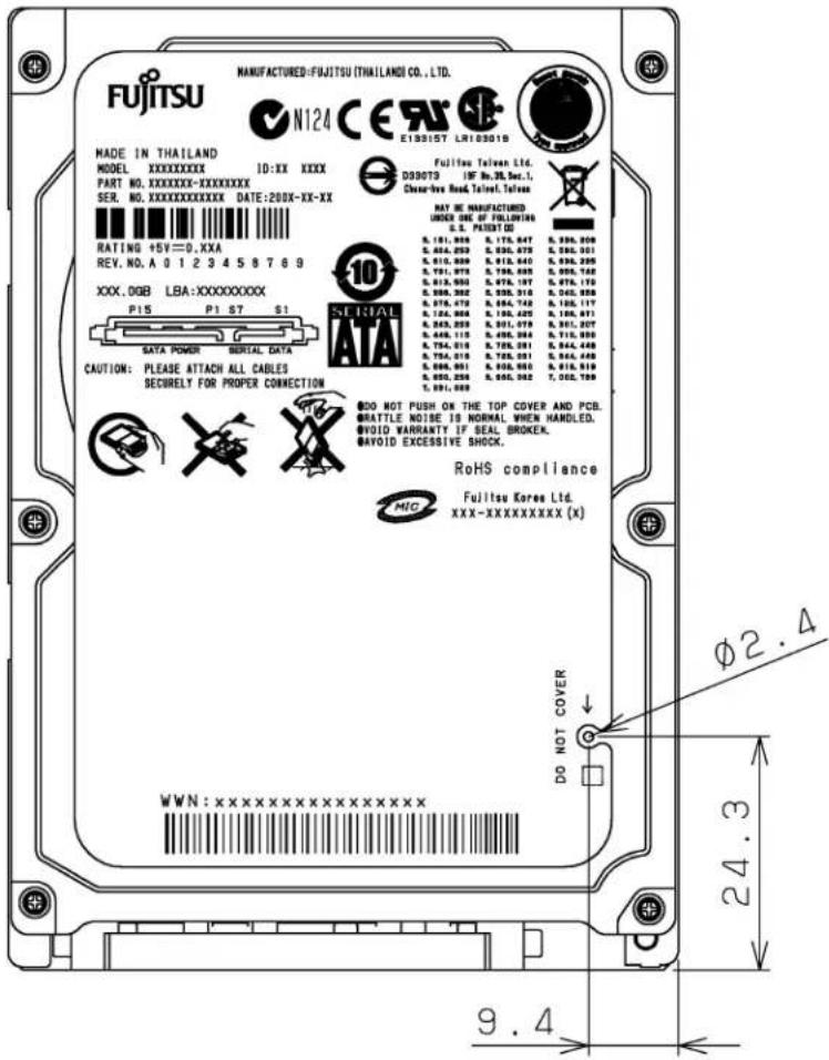
Figure 3.3 Location of breather
(4) Ambient temperature
The temperature conditions for a disk drive mounted in a cabinet refer to the ambient temperature at a point 3 cm from the disk drive. The ambient temperature must satisfy the temperature conditions described in Section 1.4, and the airflow must be considered to prevent the DE surface cover temperature from exceeding 60 °C.
Provide air circulation in the cabinet such that the PCA side, in particular, receives sufficient cooling. To check the cooling efficiency, measure the surface cover temperatures of the DE. Regardless of the ambient temperature, this surface cover temperature must meet the standards listed in Table 3.1. Figure 3.4 shows the temperature measurement point.
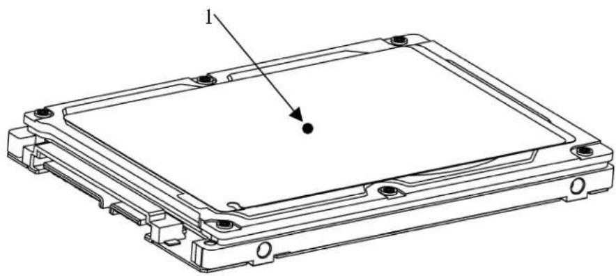
natural_image
Technical line drawing of a rectangular electronic device with mounting holes and a labeled component (no text or symbols beyond label)Figure 3.4 Surface cover temperature measurement points
Table 3.1 Surface temperature measurement points and standard values
| No. | Measurement | point |
| 1 | DE | cover 0 °C max |
Temperature
(5) Service area
Figure 3.5 shows how the drive must be accessed (service areas) during and after installation.
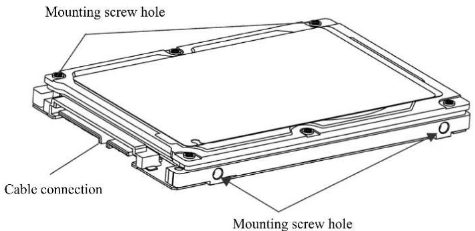
Figure 3.5 Service area
CAUTION
Data corruption: Avoid mounting the disk drive near strong magnetic sources such as loud speakers. Ensure that the disk drive is not affected by external magnetic fields.
Damage: Do not press the cover of the disk drive. Pressing it too hard, the cover and the spindle motor contact, which may cause damage to the disk drive.
Static: When handling the device, disconnect the body ground (500 kΩ or greater). Do not touch the printed circuit board, but hold it by the edges.
(6) Handling cautions
Please keep the following cautions, and handle the HDD under the safety environment.
- General notes
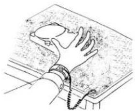
natural_image
Line drawing of a hand gripping a textured surface with a chain (no text or symbols)Wrist strap
Use the Wrist strap.
ESD mat
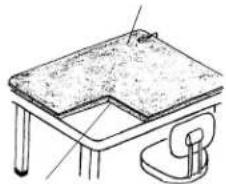
natural_image
Line drawing of a simple table setup with a flat top and a side arm (no text or symbols)Shock absorbing mat
Place the shock absorbing mat on the operation table, and place ESD mat on it.
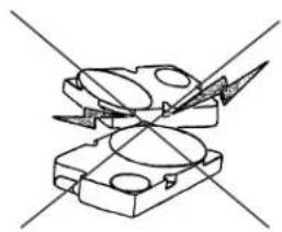
natural_image
Pure mechanical component diagram without any text, numbers, or symbolsDo not hit HDD each other.
natural_image
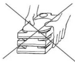
Line drawing of hands using a tool to cut or mark a stack of stacked blocks (no text or symbols)Do not stack when carrying.
natural_image
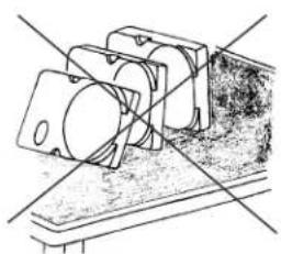
Technical line drawing of a mechanical assembly with no visible text or symbolsDo not place HDD vertically to avoid falling down.
natural_image
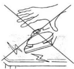
Line drawing of a hand using a tool to cut a piece of paper (no text or symbols present)Do not drop.
Figure 3.6 Handling cautions
- Installation
(1) Please use the driver of a low impact when you use an electric driver. HDD is occasionally damaged by the impact of the driver.
(2) Please observe the tightening torque of the screw strictly. M3 …… 0.49N • m (5 kgf • cm).
- Recommended equipments
| Contents | Model | Maker | |
| Wrist strap JX-1 | 200-3056-8 SUMITOMO 3M ESD | ||
| ESD mat SKY-8A (Color Seiden Mat) Achilles | |||
| Shock | Low shock driver SS-6 | 500 HIOS | |
3.3 Connections with Host System
3.3.1 Device connector
The disk drive has the SATA interface connectors listed below for connecting external devices. Figure 3.7 shows the locations of these connectors and terminals.
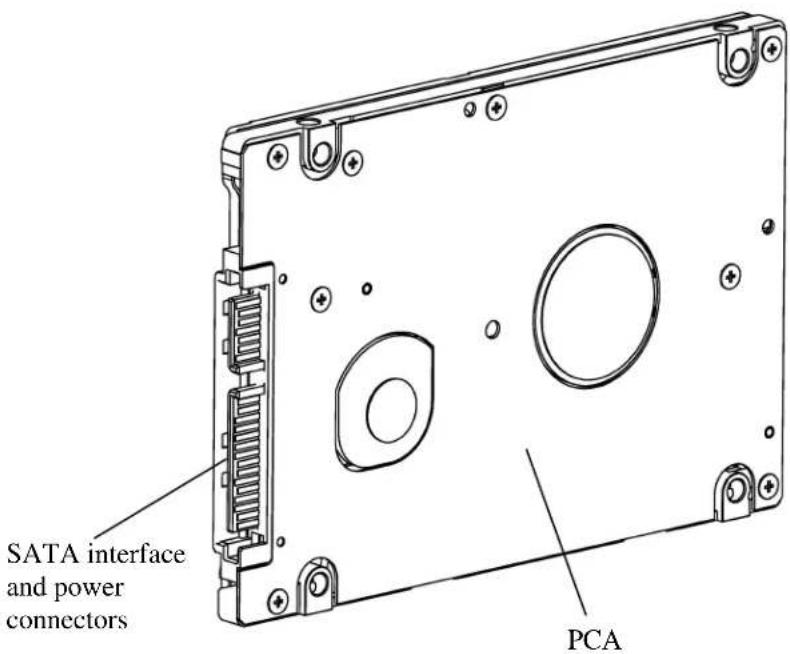
Figure 3.7 Connector locations
3.3.2 Signal segment and power supply segment
Figure 3.8 shows each segment of the SATA interface connector and pin numbers.
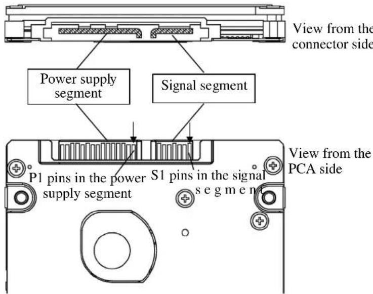
Figure 3.8 Power supply pins (CN1)
3.3.3 Connector specifications for host system
The connector of host system for mating with the disk drive must be compliant with Serial-ATA Revision 2.5 specification. For detail of requirements about SATA interface connector, refer to the "Serial-ATA Revision 2.6."
IMPORTANT
The connection reliability per number of insertion/extractions varies with the condition of the connection with the host system. Therefore, we recommend that the customer evaluate the connector on the customer's system and select it from the connectors complying with the Serial ATA Revision 2.6 specification.
3.3.4 SATA interface cable connection
The cable that connects the disk drive to the host system must be compliant with the Serial ATA Revision 2.6 specification.
3.3.5 Note about SATA interface cable connection
Take note of the following precaution about plugging a SATA interface cable into the SATA interface connector of the disk drive and plugging the connector into a host receptacle:
IMPORTANT
When plugging together the disk drive SATA interface connector and the host receptacle or SATA interface cable connector, do not apply more than 10 kgf of force in the connection direction once they are snugly and securely in position.
IMPORTANT
Connecting/removing the cable without releasing the SATA interface Latch may lead to connector damage and the loss of the Latch function. Accordingly, be sure to connect/remove the cable while releasing the Latch.
This page is intentionally left blank.

- CHAPTER 3 Installation Conditions
- Dimensions
- Mounting
- Orientation
- Frame
- IMPORTANT
- Limitation of mounting
- Ambient temperature
- Service area
- CAUTION
- Handling cautions
- - General notes
- - Installation
- - Recommended equipments
- Connections with Host System
- Device connector
- Signal segment and power supply segment
- Connector specifications for host system
- SATA interface cable connection
- Note about SATA interface cable connection
Brand : TOSHIBA
Model : MHZ2320BJ
Category : Hard Drive