MOUNT20BL - Video projector MARANTZ - Free user manual and instructions
Find the device manual for free MOUNT20BL MARANTZ in PDF.

User questions about MOUNT20BL MARANTZ
0 question about this device. Answer the ones you know or ask your own.
Ask a new question about this device
Download the instructions for your Video projector in PDF format for free! Find your manual MOUNT20BL - MARANTZ and take your electronic device back in hand. On this page are published all the documents necessary for the use of your device. MOUNT20BL by MARANTZ.
USER MANUAL MOUNT20BL MARANTZ
Model MOUNT20 User Guide
For VP-11/12/15 Series Projector
marantz®
IMPORTANT SAFETY INSTRUCTIONS
READ BEFORE INSTALLING EQUIPMENT
This product was designed and manufactured to meet strict quality and safety standards. There are, however, some installation and operation precautions which you should be particularly aware of.
- Read instructions - All the safety and operating instructions should be read before the product is operated.
- Retain instructions - The safety and operating instructions should be retained for future reference.
- Heed warnings - All warnings on the product and in the operating instructions should be adhered to.
- Follow instructions - All installation instructions should be followed.
- Use only the parts provided with the mount, along with any parts (commercially available) that are specified in this manual.
- Do not modify the mount or the parts provided with the mount.
- Do not use damaged parts. if any parts become damaged, contact your dealer.
- All bolts and screws must be tightened securely.
- Make sure not to block any ventilation openings when installing the projector.
- Special techniques and experience are required when installing the projector with this mount. Contact your dealer to install the projector for you.
- Once the projector is installed, safety checks should be conducted on a regular basis.
Warning
The ceiling should be capable of supporting a weight of at least five (5) times the projector(s) weight.
If it cannot, the ceiling must be reinforced. Proper installation procedure by qualified personnel as outlined in the installation instructions must be adhered to. Failure to do so could result in serious personal injury.
Hardware List
- Four (4) 3/8 (inch) nuts
- One (1) Ceiling Mount #1
- Four (4) 3/8 (inch) flat washers 7. Two (2) Base Plate Connectors
- Two (2) 8 (mm) screws
- One (1) Horizontal Tilt Plate #2
- Eleven (11) 6 (mm) screws 9. One (1) Horizontal Tilt Plate #3
- Eight (8) 6 (mm) rubber washers 10. One (1) Projector Plate #4]
Adjustment Ranges and Load Allowances
Horizontal Tilt (yaw) □ □ +/- 10 degrees
Vertical Tilt (tilt)□□□+/- 20 degrees
Rotation[1] [1] +/- 15 degrees
Lateral Shift□□□ +/- 2 1/4 inches
Maximum Load Allowance□□ 450 Lbs.
MOUNT20
PROJECTOR MOUNT
INSTALLATION INSTRUCTIONS
Step 1
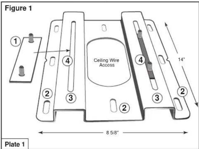
Base Plate Connectors #1 and Projector Mount Ceiling Plate 1 with ceiling mounting holes #2.
text_image
Figure 1 Ceiling Wire Access 14" 8 5/8" Plate 1Base Plate Connectors #1
Projector Mount Ceiling Plate 1
Insert Base Plate connectors #1 into the lateral positioning slots #3 as shown in#4 from the underside of Plate 1. The lateral positioning slots will give you 2 1/4" inches of lateral adjustment for projector alignment.
Step 2
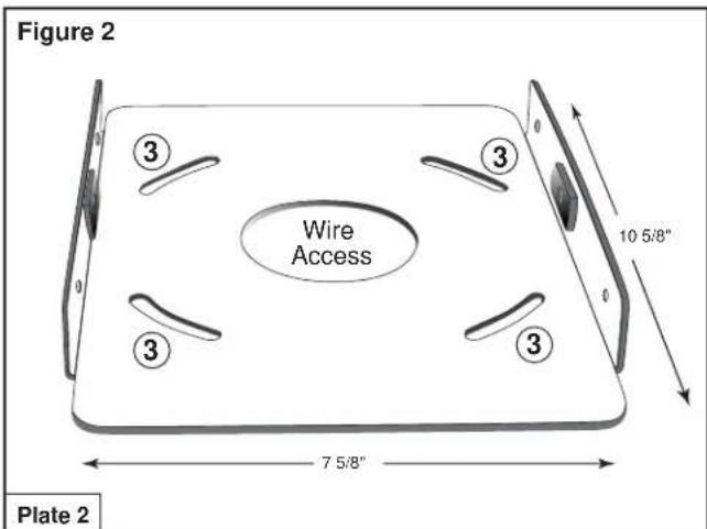
Horizontal Adjustment Plate 2 (Base Plate Connector Holes #3).
text_image
Figure 2 Wire Access 10 5/8" 7 5/8" Plate 2Base plate connector holes #3 provide 15 degrees of horizontal rotation adjustment.
Attach horizontal adjustment Plate 2 to projector mount ceiling Plate 1 using the four (4) 3/8" (inch) nuts and washers provided.
Step 2 B
Horizontal Adjustment Plate 2 (Figure 2) attached to Projector Mount Ceiling Plate 1.

text_image
Figure 3 Wire Access Plates 1 & 2Install the combined plates (above) securely to the ceiling structure in accordance with local commercial building standards.
Use suitable hardware in adequate quantity and size depending on the installation requirements. (Please note that Projector VP-12SX weighs 28.6 lbs. (13 kgs).
Step 3
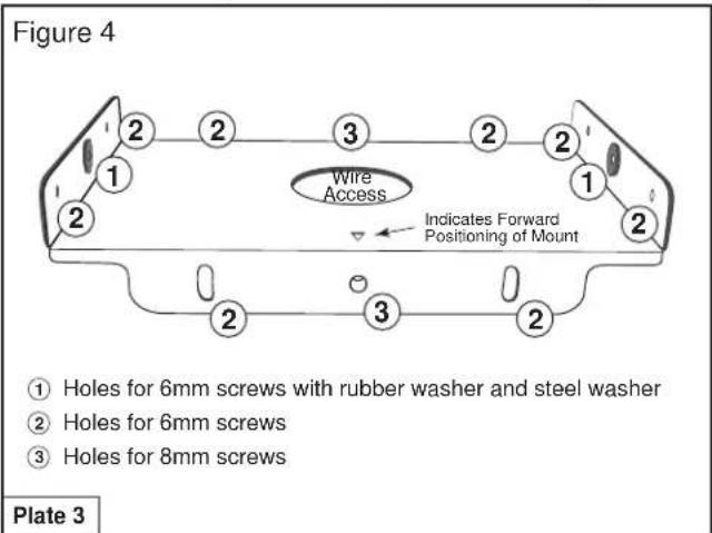
Horizontal Tilting Plate 3 Projector Mounting Plate 4
text_image
Figure 4 2 2 3 2 2 1 Wire Access Indicates Forward Positioning of Mount ① Holes for 6mm screws with rubber washer and steel washer ② Holes for 6mm screws ③ Holes for 8mm screws Plate 3Attach Horizontal Tilting Plate 3 to the previously combined plates (already installed on ceiling) using the two (2) 8 (mm) screws and four (4) 6 (mm) screws provided, as indicated in Figure 4. Install two (2) 6 (mm) screws with rubber spacers and metal washers into the welded metal studs (indicated #1).
Step 3 B
Horizontal Tilting Plate 3 Attached to Plates 1 and 2.

text_image
Figure 5 Tilting Capability Tilting Capability Plate 3The newly combined Plate 3 provides 10^0 degrees of horizontal tilt. When positioned, tighten with screws provided.
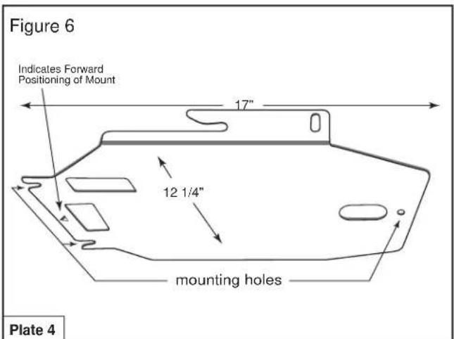
Step 4
text_image
Figure 6 Indicates Forward Positioning of Mount 17" 12 1/4" mounting holes Plate 4Invert the projector and place it on a soft and flat surface. Align the three (3) rubber spacers provided with the three (3) 6(mm) mounting holes on the projector and secure with three (3) 6(mm) screws provided.
Step 4 B
Projector Mounting Plate 4 (continued)

text_image
Figure 7 CEILING Mount Side 20° Tilt 20° Tilt Projector Side Plate 4Work in a group of 2 or more to carry the projector and follow manufacturer's guidelines for relocating as stated in the VP-12SX owner's manual.
Lift and slide the projector onto the 6 (mm) screws previously installed in the metal studs of the plate on the ceiling (see arrow in Figure 7). Tighten the 6 (mm) screws on both sides of the mount and install four (4) 6 (mm) screws and washers into the side of the projector Mounting Plate 4.
Projector Mounting Plate 4 connected to Mounting Plate 3

text_image
Figure 8 Mounts Fully Assembled Ceiling Side Projector SideSequence of Assembly of Projector Mounting Plates
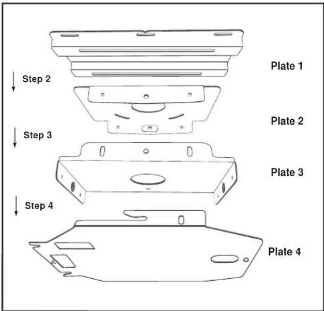
text_image
Step 2 Step 3 Step 4 Plate 1 Plate 2 Plate 3 Plate 4marantz®
100 Corporate Drive
Mahwah, NJ 07430
Phone: 201 762-6500
You can find your nearest authorized distributor or dealer
on our website at: www.marantz.com
Marantz Templates
Base Plate Connectors

text_image
6.50" 1.375" 5.00"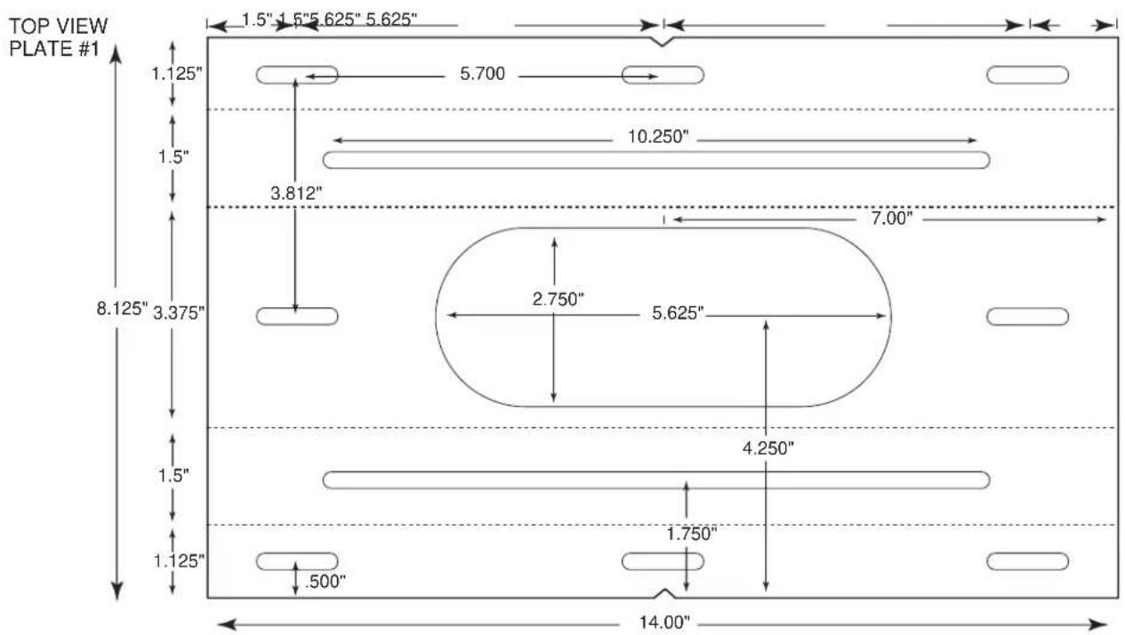
text_image
TOP VIEW PLATE #1 1.5" 1.5" 5.625" 5.625" 1.125" 5.700 10.250" 3.812" 7.00" 8.125" 3.375" 2.750" 5.625" 4.250" 1.5" 1.125" 1.750" .500" 14.00"END VIEW PLATE #1
text_image
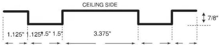
CEILING SIDE 1.125" 1.125†.5" 1.5" 3.375" 7/8"marantz
100 Corporate Drive,
Mahwah, NJ 07430
Phone:201762-6500
You can find your nearest authorized distributor or dealer
on our website at: www.marantz.com
MOUNT20 Dimensions

text_image
+ / 10 degree + / 15 degree 13.2" (3335.5 mm) 60 mm 4.05" (103.0 mm)