ET2700INKS - All-in-One ASUS - Free user manual and instructions
Find the device manual for free ET2700INKS ASUS in PDF.
| Product Type | All-in-One Computer |
| Brand | ASUS |
| Model | ET2700INKS |
| Screen | Touch LCD (depending on model), optimal resolution |
| Processor | Intel Core i7-2600, i7-2600S, i5-2400S, i5-2405S, i3-2120 (depending on configuration) |
| RAM Memory | Not specified (expandable) |
| Storage | Internal hard drive (not specified) |
| Network connectivity | RJ-45 LAN, integrated Wi-Fi (depending on model) |
| Ports | USB 2.0 (x2), USB 3.0 (x2), E-SATA + USB 2.0 combo, HDMI input, VGA input, memory card reader, audio jacks (line out, microphone, subwoofer) |
| Audio | Integrated stereo speakers, optional subwoofer, DTS UltraPC II certification |
| Webcam | Integrated with digital microphone |
| Power supply | AC power adapter 100-240 V AC, DC output |
| Operating system | Windows 7 (pre-installed) |
| Special features | Touch screen, Device Share, OSD menu, F9 recovery, VESA200 wall mount |
| Security | Kensington lock port, compliance FCC, CE, UL, ENERGY STAR |
| Cleaning | Use a soft cloth and glass cleaner, do not spray directly |
| Warranty | Warranty does not cover user disassembly |
| Repairability | Lithium-ion battery replaceable only with an equivalent model |
Frequently Asked Questions - ET2700INKS ASUS
User questions about ET2700INKS ASUS
0 question about this device. Answer the ones you know or ask your own.
Ask a new question about this device
Download the instructions for your All-in-One in PDF format for free! Find your manual ET2700INKS - ASUS and take your electronic device back in hand. On this page are published all the documents necessary for the use of your device. ET2700INKS by ASUS.
USER MANUAL ET2700INKS ASUS
Copyright © 2011 ASUSTeK COMPUTER INC. All Rights Reserved.
No part of this manual, including the products and software described in it, may be reproduced, transmitted, transcribed, stored in a retrieval system, or translated into any language in any form or by any means, except documentation kept by the purchaser for backup purposes, without the express written permission of ASUSTeK COMPUTER, INC. ("ASUS").
Products and corporate names mentioned in this manual may or may not be registered trademarks or copyrights of their respective companies, and are used for identification purposes only. All trademarks are the property of their respective owners.
Every effort has been made to ensure that the contents of this manual are correct and up to date. However, the manufacturer makes no guarantee regarding the accuracy of its contents, and reserves the right to make changes without prior notice.
Contents
Contents 3
Notices. 5
Federal Communications Commission Statement. 5
Canadian Department of Communications Statement. 6
IC Radiation Exposure Statement for Canada. 6
Declaration of Conformity (R&TTE directive 1999/5/EC) 6
CE Mark Warning. 7
Wireless Operation Channel for Different Domains 7
France Restricted Wireless Frequency Bands. 8
REACH 9
Global Environmental Regulation Compliance and Declaration 10
ASUS Recycling/Takeback Services 10
UL Safety Precaution. 10
ENERGY STAR complied product. 11
DTS Certified Audio System 11
ET2700 Series CPU Configurations 11
Safety information. 12
Setting up your system 12
Care during use. 12
Sound Pressure Warning 13
TV Tuner (on selected models) 13
DC Fan Warning 13
Notes for this manual. 13
Welcome 14
Package contents 14
Getting to know your All-in-one PC 15
Front view. 15
Rear view 17
Side views 19
Using the touch screen. 21
Showing the touch pointer 21
Cleaning the touch screen. 22
Using the keyboard 23
Using the On Screen Display (OSD) Menu 24
OSD function instruction 24
Input signal selection 25
Positioning your All-in-one PC 26
Placing on the desktop 26
Mounting to the wall 27
Setting up your All-in-one PC 30
Connecting the wired keyboard and mouse 30
Connecting the wireless keyboard and mouse 30
Powering on the system. 31
Powering off 31
Using the Device Share function 32
Device Share Cable Requirement 32
Configuring a wireless connection 34
Configuring a wired connection 35
Using a static IP 35
Using a dynamic IP (PPPoE) 37
Connecting to external audio devices 40
Configuring audio output settings 40
Recovering your system 42
Using the hidden partition. 42
Recovering the OS to the Factory Default Partition (F9 Recovery) 42
Backing up the Factory Default Environment Data to a USB Drive (F9 Backup)42
Using the USB storage device (USB Restore) 43
Notices
Federal Communications Commission Statement
This device complies with Part 15 of the FCC Rules. Operation is subject to the following two conditions:
This device may not cause harmful interference, and
- This device must accept any interference received including interference that may cause undesired operation.
This equipment has been tested and found to comply with the limits for a Class B digital device, pursuant to Part 15 of the FCC Rules. These limits are designed to provide reasonable protection against harmful interference in a residential installation. This equipment generates, uses and can radiate radio frequency energy and, if not installed and used in accordance with manufacturer's instructions, may cause harmful interference to radio communications. However, there is no guarantee that interference will not occur in a particular installation. If this equipment does cause harmful interference to radio or television reception, which can be determined by turning the equipment off and on, the user is encouraged to try to correct the interference by one or more of the following measures:
Reorient or relocate the receiving antenna.
- Increase the separation between the equipment and receiver.
- Connect the equipment to an outlet on a circuit different from that to which the receiver is connected.
- Consult the dealer or an experienced radio/TV technician for help.
CAUTION: Any changes or modifications not expressly approved by the guarantee of this device could void the user's authority to operate the equipment.
RF exposure warning
This equipment must be installed and operated in accordance with provided instructions and the antenna(s) used for this transmitter must be installed to provide a separation distance of at least 20cm from all persons and must not be co-located or operating in conjunction with any other antenna or transmitter. End-users and installers must be provided with antenna installation instructions and transmitter operating conditions for satisfying RF exposure compliance.
Canadian Department of Communications Statement
This digital apparatus does not exceed the Class B limits for radio noise emissions from digital apparatus set out in the Radio Interference Regulations of the Canadian Department of Communications.
This class B digital apparatus complies with Canadian ICES-003.
IC Radiation Exposure Statement for Canada
This equipment complies with IC radiation exposure limits set forth for an uncontrolled environment. To maintain compliance with IC RF exposure compliance requirements, please avoid direct contact to the transmitting antenna during transmitting. End users must follow the specific operating instructions for satisfying RF exposure compliance.
Operation is subject to the following two conditions:
This device may not cause interference and
- This device must accept any interference, including interference that may cause undesired operation of the device.
Declaration of Conformity (R&TTE directive 1999/5/EC)
The following items were completed and are considered relevant and sufficient:
Essential requirements as in [Article 3]
Protection requirements for health and safety as in [Article 3.1a]
- Testing for electric safety according to [EN 60950]
Protection requirements for electromagnetic compatibility in [Article 3.1b]
- Testing for electromagnetic compatibility in [EN 301 489-1] & [EN 301 489-17]
Effective use of the radio spectrum as in [Article 3.2]
- Radio test suites according to [EN 300 328-2]
CE Mark Warning
This is a Class B product, in a domestic environment, this product may cause radio interference, in which case the user may be required to take adequate measures.

CE marking for devices without wireless LAN/Bluetooth
The shipped version of this device complies with the requirements of the EEC directives 2004/108/EC "Electromagnetic compatibility" and 2006/95/EC "Low voltage directive".

CE marking for devices with wireless LAN/ Bluetooth
This equipment complies with the requirements of Directive 1999/5/EC of the European Parliament and Commission from 9 March, 1999 governing Radio and Telecommunications Equipment and mutual recognition of conformity.
Wireless Operation Channel for Different Domains
N. America
2.412-2.462 GHz
Ch01 through CH11
Japan
2.412-2.484 GHz
Ch01 through Ch14
Europe ETSI
2.412-2.472 GHz
Ch01 through Ch13
France Restricted Wireless Frequency Bands
Some areas of France have a restricted frequency band. The worst case maximum authorized power indoors are:
10mW for the entire 2.4 GHz band (2400 MHz-2483.5 MHz)
100mW for frequencies between 2446.5 MHz and 2483.5 MHz

Channels 10 through 13 inclusive operate in the band 2446.6 MHz to 2483.5 MHz.
There are few possibilities for outdoor use: On private property or on the private property of public persons, use is subject to a preliminary authorization procedure by the Ministry of Defense, with maximum authorized power of 100mW in the 2446.5-2483.5 MHz band. Use outdoors on public property is not permitted.
In the departments listed below, for the entire 2.4 GHz band:
Maximum authorized power indoors is 100mW
Maximum authorized power outdoors is 10 ~mW
Departments in which the use of the 2400-2483.5 MHz band is permitted with an EIRP of less than 100mW indoors and less than 10mW outdoors:
01 Ain 02 Aisne 03 Allier 05 Hautes Alpes
08 Ardennes 09 Ariège 11 Aude 12 Aveyron 16 Charente
24Dordogne 25 Doubs 26 Drome 32 Gers 36 Indre
37 Indre et Loire 41 Loir et Cher 45 Loiret 50 Manche 55 Meuse
58 Nièvre 59 Nord 60 Oise 61 Orne 63 Puy du Dôme
64 Pyrénées Atlantique 66 Pyrénées Orientales 67 Bas Rhin 68 Haut Rhin
70 Haute Saône 71 Saône et Loire 75 Paris 82 Tarn et Garonne
84 Vaucluse 88 Vosges 89 Yonne
90 Territoire de Belfort 94 Val de Marne
This requirement is likely to change over time, allowing you to use your wireless LAN card in more areas within France. Please check with ART for the latest information (www.artelecom.fr)

Your WLAN Card transmits less than 100mW , but more than 10mW .
NO DISASSEMBLY
The warranty does not apply to the products that have been disassembled by users
Lithium-Ion Battery Warning
CAUTION: Danger of explosion if battery is incorrectly replaced. Replace only with the same or equivalent type recommended by the manufacturer. Dispose of used batteries according to the manufacturer's instructions.
No Exposure to Liquids
DO NOT expose to or use near liquids, rain, or moisture. This product is not waterproof or oil-proof.

This symbol of the crossed out wheeled bin indicates that the product (electrical, electronic equipment, and mercury-containing button cell battery) should not be placed in municipal waste. Check local regulations for disposal of electronic products.

DO NOT throw the battery in municipal waste. The symbol of the crossed out wheeled bin indicates that the battery should not be placed in municipal waste.
REACH
Complying with the REACH (Registration, Evaluation, Authorization, and Restriction of Chemicals) regulatory framework, we publish the chemical substances in our products at ASUS REACH website at http://csr.asus.com/english/REACH.htm.
Global Environmental Regulation Compliance and Declaration
ASUS follows the green design concept to design and manufacture our products, and makes sure that each stage of the product life cycle of ASUS product is in line with global environmental regulations. In addition, ASUS disclose the relevant information based on regulation requirements.
Please refer to http://csr.asus.com/english/Compliance.htm for information disclosure based on regulation requirements ASUS is complied with:
Japan JIS-C-0950 Material Declarations
EU REACH SVHC
Korea RoHS
Swiss Energy Laws
ASUS Recycling/Takeback Services
ASUS recycling and takeback programs come from our commitment to the highest standards for protecting our environment. We believe in providing solutions for you to be able to responsibly recycle our products, batteries, other components as well as the packaging materials. Please go to http://csr.asus.com/english/Takeback.htm for detailed recycling information in different regions.
UL Safety Precaution
To meet safety requirements, the All-in-one PC must be mounted to a bracket which guarantees the necessary stability considering the weight of the All-in-one PC. The All-in-one PC shall only be mounted and used with UL listed mounting adapters and brackets (e.g. VESA).
ENERGY STAR complied product

ENERGY STAR
ENERGY STAR is a joint program of the U.S. Environmental Protection Agency and the U.S. Department of Energy helping us all save money and protect the environment through energy efficient products and practices.
All ASUS products with the ENERGY STAR logo comply with the ENERGY STAR standard, and the power management feature is enabled by default. The monitor and computer are automatically set to sleep after 15 and 30 minutes
of user inactivity. To wake your computer, click the mouse or press any key on the keyboard.
Please visit http://www.energy.gov/powermanagement for detail information on power management and its benefits to the environment. In addition, please visit http://www.energystar.gov for detail information on the ENERGY STAR joint program.

ENERGY STAR is NOT supported on Freedos and Linux-based products.
DTS Certified Audio System


Surround Sensation
UltraPC
Audio system is manufactured under license from DTS Licensing Limited. DTS, the Symbol, & DTS and the Symbol together are registered trademarks, and DTS Ultra PC II is a trademark, of DTS (BVI) Limited (in Hong Kong and China) and DTS, Inc. (outside of Hong Kong and China). © DTS, Inc. All Rights Reserved.
ET2700 Series CPU Configurations
i7-2600 @3.0GHz, Turbo Boost not available
i7-2600S @2.80GHz, Turbo Boost up to 3.8GHz
i5-2400S @2.50GHz, Turbo Boost up to 3.3GHz
i5-2405S @2.50GHz, Turbo Boost up to 3.3GHz
i3-2120 @3.30GHz
Safety information
Your All-in-one PC ET2700 Series is designed and tested to meet the latest standards of safety for information technology equipment. However, to ensure your safety, it is important that you read the following safety instructions.
Setting up your system
- Read and follow all instructions in the documentation before you operate your system.
- Do not use this product near water or a heated source such as a radiator.
- Set up the system on a stable surface.
- Openings on the chassis are for ventilation. Do not block or cover these openings. Ensure that you leave plenty of space around the system for ventilation. Never insert objects of any kind into the ventilation openings.
- Use this product in environments with ambient temperatures between 0^ C and 40^ C .
- If you use an extension cord, ensure that the total ampere rating of the devices plugged into the extension cord does not exceed its ampere rating.
Care during use
- Do not walk on the power cord or allow anything to rest on it.
- Do not spill water or any other liquids on your system.
- When the system is turned off, a small amount of electrical current still flows. Always unplug all power, modem, and network cables from the power outlets before cleaning the system.
-
The touch screen requires periodic cleaning to achieve the best touch sensitivity. Keep the screen clean from foreign objects or excessive dust accumulation. To clean the screen:
-
Turn off the system and disconnect the power cord from the wall.
Spray a small amount of a household glass cleaner onto the supplied cleaning cloth and gently wipe the screen surface. - Do not spray the cleaner directly on the screen.
-
Do not use an abrasive cleaner or a coarse cloth when cleaning the screen.
-
If you encounter the following technical problems with the product, unplug the power cord and contact a qualified service technician or your retailer.
The power cord or plug is damaged.
Liquid has been spilled into the system.
- The system does not function properly even if you follow the operating instructions.
The system was dropped or the cabinet is damaged.
The system performance changes.
Sound Pressure Warning
Excessive sound pressure from earphones or headphones can cause hearing damage or loss. Adjustment of the volume control as well as the equalizer to settings other than the center position may increase the earphones or headphones output voltage and the sound pressure level.
TV Tuner (on selected models)
Note to CATV System Installer—This reminder is provided to call the CATV systems installer's attention to Section 820-93 of the National Electric Code, which provides guidelines for proper grounding and, in particular, specify that the Coaxial cable shield be connected to the grounding system of the building as close to the point of cable entry as practical.
DC Fan Warning
Please note that the DC fan is a moving part that may cause DANGER. Ensure to keep your body from the moving fan blades.
Notes for this manual
To ensure that you perform certain tasks properly, take note of the following symbols used throughout this manual.

WARNING: Vital information that you MUST follow to prevent injury to yourself.

IMPORTANT: Instructions that you MUST follow to complete a task.

TIP: Tips and useful information that help you complete a task.

NOTE: Additional information for special situations.
All illustrations and screenshots in this manual are for reference only. Actual product specifications and software screen images may vary with territories. Visit the ASUS website at www.asus.com for the latest information.
Welcome
Congratulations on your purchase of All-in-one PC ET2700 Series. The following illustrations display the package contents of your new product. If any of the following items is damaged or missing, contact your retailer.
Package contents
| All-in-one PC ET2700 Series | Keyboard (wired or wireless, optional) | Mouse (wired or wireless, optional) |
| AC adapter | Power cord | Quick Start Guide |
| Remote Control (optional) | Subwoofer (optional) | Note: The keyboard, mouse, power supply, remote control, and KBM USB receiver dongle illustrations are for reference only. Actual product specifications may vary with territories. |
| Warranty Card | KBM USB receiver dongle (optional) | |
| Note: The keyboard, mouse, power supply, remote control, and KBM USB receiver dongle illustrations are for reference only. Actual product specifications may vary with territories. |
Getting to know your All-in-one PC
Front view
Refer to the following diagram to identify the components on this side of the system.
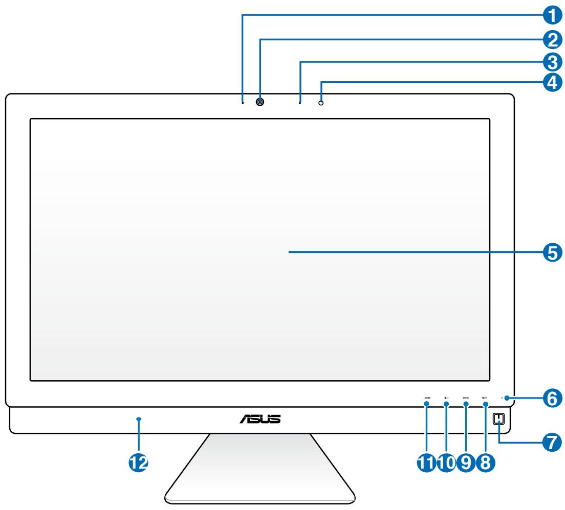
Webcam LED
Indicates that the built-in webcam is enabled.
Webcam
The built-in webcam with the built-in digital microphone allows you to start video chats online.
3 Digital Microphone (Built-in)
The built-in digital microphone can be used for video conferencing, voice narrations, audio recordings, and multimedia applications.
Remote Control Receiver
The remote control receiver receives the infrared signal from the remote control.
5 LCD display (Touch-enabled function on selected models)
The LCD display features optimal resolution. Touch-enabled models bring digital life to your fingertips.
6 Hard Disk Drive LED
Indicates hard disk drive activity.
7 Power switch
The power switch allows you to switch the system ON/OFF.
8 Volume Increase Button
When using the All-in-one PC as a standard desktop LCD monitor, touch this button to increase the volume.
9 MENU Button
Touch to display the menu. Touch this button to enter/select the highlighted icon (function) while the OSD is activated.
10 Volume Decrease Button
When using the All-in-one PC as a standard desktop LCD monitor, touch this button to decrease the volume.
11 MODE Button
Touch to switch the display signal source. When switched to HDMI-in and VGA-in, the All-in-one PC can be used as a standard desktop LCD monitor.
Audio Speaker
The built-in stereo speaker system allows you to hear audio without additional attachments. The multimedia sound system features an integrated digital audio controller that produces rich, vibrant sound. (Results improve with external stereo headphones or speakers.) Audio features are software controlled.
Rear view
Refer to the following diagram to identify the components on this side of the system.
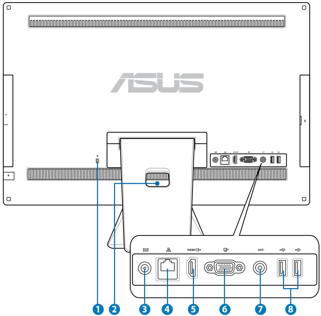


Kensington® Lock port
The Kensington® lock port allows the computer to be secured using Kensington® compatible security products. These security products usually include a metal cable and lock that prevent the computer to be removed from a fixed object.
2 Cable Holder
Gather all the cables with this cable holder.
3 DCIN Power input
The supplied power adapter converts AC power to DC power for use with this jack. Power supplied through this jack supplies power to the PC. To prevent damage to the PC, always use the supplied power adapter.

The power adapter may become warm or hot when in use. Do not cover the adapter and keep it away from your body.
4 品 LAN port
The eight-pin RJ-45 LAN port supports a standard Ethernet cable for connection to a local network.
5 HDMI Input Port
HDMI (High-Definition Multimedia Interface) is an uncompressed all-digital audio/video interface between any HDMI-labeled audio/video source, such as set-top box or DVD player.
Display (Monitor) Input
The display input port supports a standard VGA cable and helps turn your All-in-one PC into a larger display for your Notebook PC or other devices.
Antenna Input (on selected models)
The antenna input is for TV frequency signal and allows for use with the digital TV antenna or input from subscription television services. The antenna can receive digital TV. Cable service connection can receive digital TV, analog TV, depending on paid services.
USB 2.0 ports
The Universal Serial Bus (USB) port is compatible with USB devices such as keyboards, mouse devices, cameras, and hard disk drives.
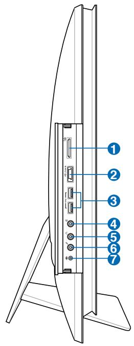
Side views
Refer to the following diagrams to identify the components on both sides of the system.
Memory card reader
This All-in-one PC has a built-in memory card reader that supports SD cards used in devices like digital cameras, MP3 players, mobile phones, and PDAs.
E-SATA + USB 2.0 Combo port
This port connects to an external Serial-ATA hard disk drive.

DO NOT insert a different connector to the external SATA port.
3 USB 3.0 ports
The Universal Serial Bus (USB) port is compatible with USB devices such as keyboards, mouse devices, cameras, and hard disk drives.
4 Line Out / S/PDIF Out jack
The line out jack (3.5mm) is used to connect the system's audio out signal to amplified speakers. Using this jack automatically disables the built-in speakers.
5 Headphone jack
The stereo headphone jack (3.5mm) is used to connect the system's audio out signal to headphones. Using this jack automatically disables the built-in speakers.
6 Microphone jack
The microphone jack is designed to connect to a microphone used for video conferencing, voice narrations, or simple audio recordings.
7 Subwoofer jack (on selected models)
The proprietary subwoofer jack is used to connect to the ASUS All-in-one PC subwoofer. The subwoofer allows you to enjoy vibrant bass (low frequency) sounds in your multimedia applications.

The subwoofer jack can ONLY be connected to All-in-one PC subwoofoers or sound devices by ASUS. DO NOT connect other devices to this jack. Doing so may damage the device.
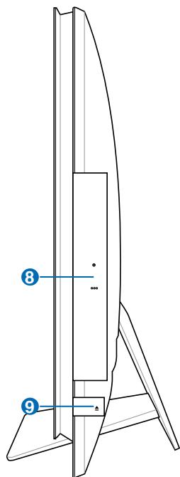
8 Optical Drive
The built-in optical drive may support compact discs (CD), digital video discs (DVD), and/or Blu-ray discs (BD) and may have recordable (R) or re-writable (RW) capabilities. See the marketing specifications for details on each model.
Optical Drive Electronic Eject
The optical drive eject has an electronic eject button for opening the tray. You can also eject the optical drive tray through any software player or by right clicking the optical drive in Windows "Computer" and selecting Eject.
Using the touch screen
All-in-one PC brings digital life to your fingertips. With a few touches, you can make All-in-one PC work at your command. Your touch functions like a mouse device:
- Touch = left-click on the mouse
- Touch and hold = right-click on the mouse
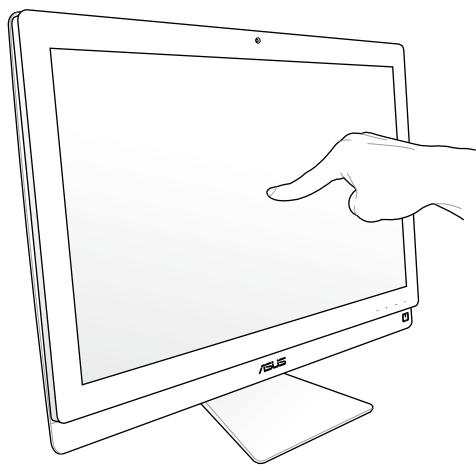

The touch-enabled screen is available on selected models.
Showing the touch pointer
The touch pointer, or virtual mouse, helps you use the touch-enabled screen more conveniently. To show the touch pointer
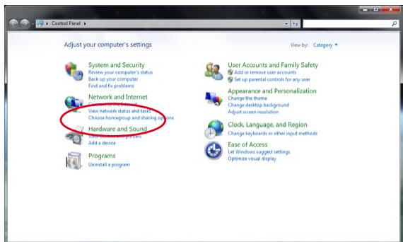
- From the Windows® desktop, click Start > Control Panel > View Devices and Printer.
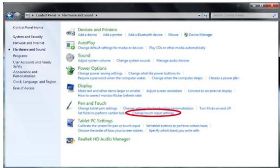
- Click Change touch input settings.
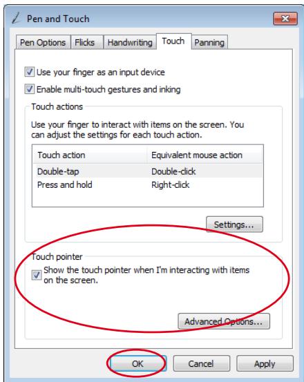
- Click the Touch tab on the top and click the box before Show the touch pointer when I'm interacting with items on the screen. Click OK to finish the configuration.
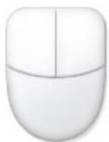
- You will see a virtual mouse on the screen when you touch the screen.
Cleaning the touch screen
The touch screen requires periodic cleaning to achieve the best touch sensitivity. Keep the screen clean from foreign objects or excessive dust accumulation. To clean the screen:
- Turn off the system and disconnect the power cord from the wall.
- Spray a small amount of a household glass cleaner onto the supplied cleaning cloth and gently wipe the screen surface.
- Do not spray the cleaner directly on the screen.
- Do not use an abrasive cleaner or a coarse cloth when cleaning the screen.
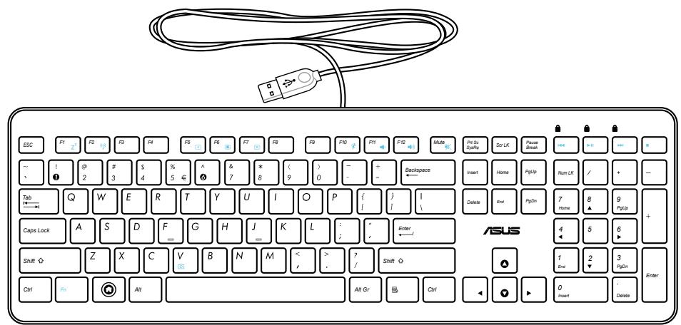
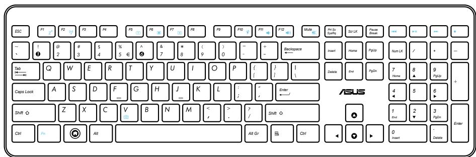
Using the keyboard
Your All-in-one PC comes with a wired or wireless keyboard that facilitates your control of the system.

The following keyboard illustration is for reference only. Actual product specifications may vary with territories.
Using the On Screen Display (OSD) Menu
The On Screen Display (OSD) menu appears if you:
- press the MENU button in the front panel; or
- connect the HDMI or VGA cable to the rear HDMI-input or Display-input port.
OSD function instruction
To display the OSD menu, press the MENU button on the front panel. To navigate through the OSD functions or modify OSD settings, press the Volume Increase ( / + ) / Decrease ( / - ) keys. To activate the selected function, press the MENU button.
1. Panel Off
This function allows you to turn off the display panel of the All-in-one PC on. Press the MENU button to activate this function.
2. Color
- Brightness: The adjusting range is from 0 to 100.
- Contrast: The adjusting range is from 0 to 100.
Color Temp.: Contains four color modes including Cool, Normal, Warm, and User mode.
3. Image
- Sharpness: The adjusting range is from 0 to 100.
- Aspect Control: Adjusts the aspect ratio to "Full" or "OverScan". This function is configurable only when you use the All-in-one PC as a standard desktop LCD monitor.
- Auto Adjust: Adjusts the horizontal position (H-Position) and the vertical position (V-Position) of the image. This function is configurable only when you use the All-in-one PC as a standard desktop LCD monitor and set the Display-input port as the input source.
4. Input Select
PC: Sets the All-in-one PC as the display signal source.
- HDMI: Sets the HDMI-input port as the display signal source.
VGA: Sets the Display-input port as the display signal source.
- HDMI with Device Share: Sets the HDMI-input port as the display signal source and enable the Device Share function.
- VGA with Device Share: Sets the Display-input port as the display signal source and enable the Device Share function.

The HDMI with Device Share and VGA with Device Share items appear only when you enable the Device Share function under the System Setup OSD menu and replace the HDMI and VGA items.
5. System Setup
- OSD Setup:
- Adjusts the horizontal position (H-Position) / vertical position (V-Position) of the OSD menu.
- Adjusts the OSD timeout from 10 to 120 seconds.
- Enables or disables the DDC/CI (Display Data Channel/Command Interface) function.
Information: Shows the monitor information.
- Language: Allows you to set the OSD language.
Device Share: Enables or disables the Device Share function. When enabled, the HDMI and VGA items under the Input Select menu will be replaced as HDMI with Device Share and VGA with Device Share.
- All Reset: Allows you to reset all OSD settings.
Input signal selection
An Input Select OSD menu appears when you connect the HDMI or VGA cable to the rear HDMI-input or Display-input port. Use the Volume Increase (↑/+) / Decrease (↓/- ) buttons to navigate through the input options and press the MENU button to activate the option. Refer to 4. Input Select in the previous section for details.
Positioning your All-in-one PC
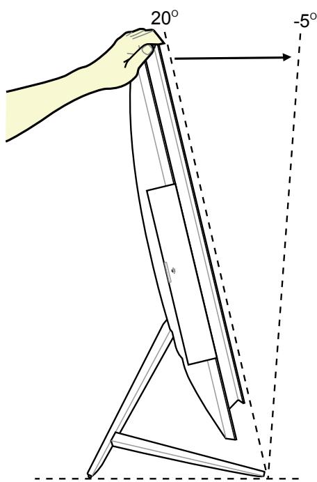
Placing on the desktop
Place your All-in-one PC on a flat surface such as a table or desk by setting the stand on the platform. Tilt the display panel to an angle between 5 degrees forward to 20 degrees backwards from an upright position for visual comfort.

Avoid tilting hazards and potential breakage by tilting the display panel within the given range.
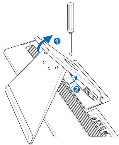
Mounting to the wall
To mount your All-in-one PC to the wall, purchase an optional wall mount adapter and a wall mount kit (VESA200 with pad and bracket). Install the wall mount components according to the following instructions.
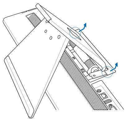
- To release the stand, place the All-in-one PC face-down first, resting the display panel on a flat even surface. Lift the stand upwards (1). Use a slotted screwdriver to lift up the lower back cover (2).
- Remove the upper back cover.
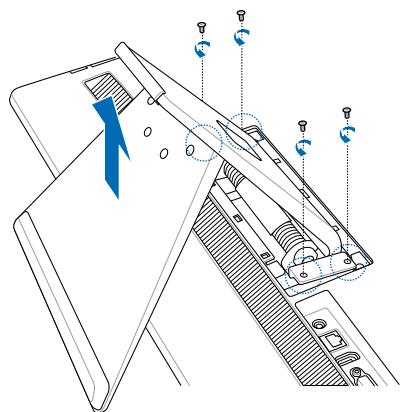
- Remove the four screws on the stand and save for future reinstallation. Take out the stand and put it aside.
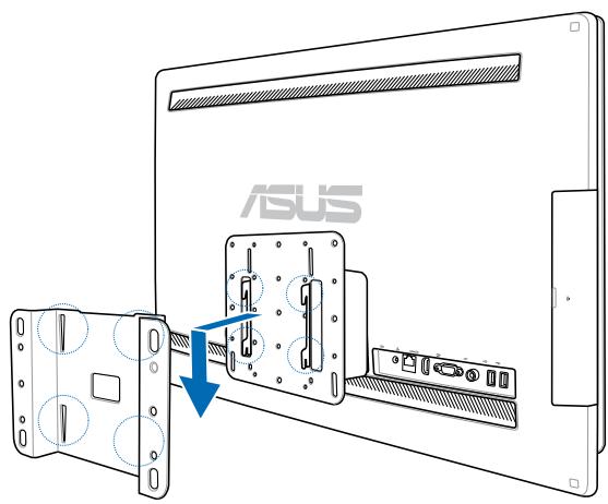
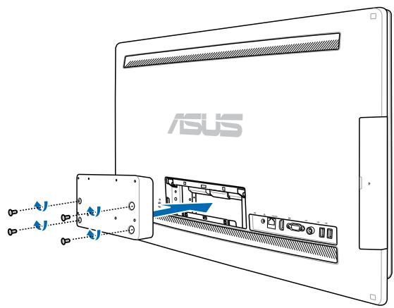
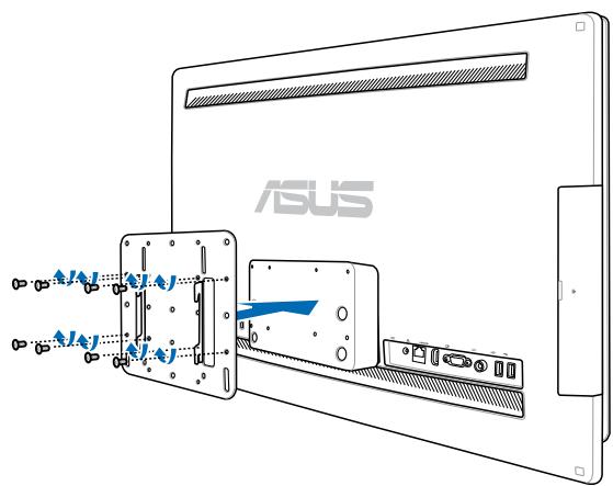
- Align the wall mount adapter to the holes at the back of the All-in-one PC and secure it with the four screws you removed in step 3
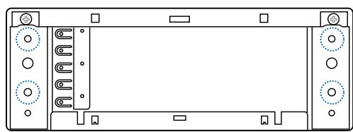
- Secure the wall mount pad to the adapter with the eight screws (M3 x 8L) that came with the kit, noting the correct orientation.
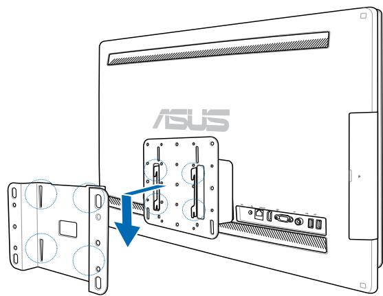
- By following the instructions in the installation manual that came with your wall mount kit (VESA200), fasten the wall mount bracket to the wall using the four screws (M4 x 10L) provided in the kit. Upright your All-in-one PC and hook it on to the wall by sliding the grooves of the wall mount pad into the bracket.

The wall mount kit in this illustration is for reference only.

- For machine ventilation, be sure to leave a distance of at least 6cm between the All-in-one PC and the wall.
- The wall mount kit should comply with VESA standards.
- To ensure safety, please read the wall mount kit installation manual carefully before mounting your All-in-one PC to the wall.
- At least two persons are required to install or remove the All-in-one PC onto and from the wall to avoid hazard of falling objects and breakage. Qualified personnel is recommended.
- The wall should be able to sustain four times the weight of the All-in-on PC and wall mount components combined (40kg at least). The mounting location must be able to withstand earthquake or other impacts. Cement or masonry walls recommended.
Setting up your All-in-one PC
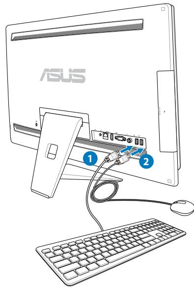
Connecting the wired keyboard and mouse
Connect the keyboard 1 and the mouse 2 to the USB port on the rear panel. You may also connect the keyboard and mouse to the USB port on the left side of the panel if the keyboard cable is not long enough.
Connecting the wireless keyboard and mouse
- Install batteries to the wireless keyboard and mouse.
- Plug the wireless dongle for keyboard and mouse to a USB port.
- You can begin using the wireless keyboard and mouse.
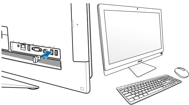

- Simply reconnect if the wireless keyboard and mouse lose connection. Avoid other nearby WiFi devices at least 20~cm as they may interfere with the connection.
- The illustrations above are for reference only. Actual appearances and specifications (wired or wireless) of the keyboard and mouse may vary by territory.
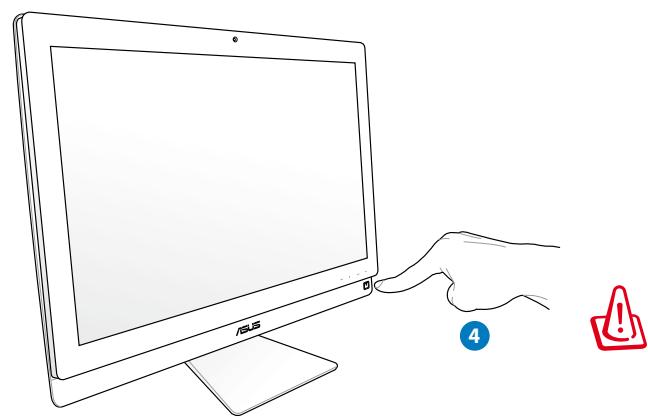
Powering on the system
Connect the supplied AC adapter to the DC IN jack on the rear panel (1 2 3, wall outlet voltage 100Vac-240Vac) and then press the Power switch on the right (4) to turn on the system.
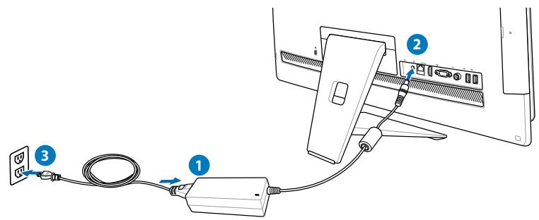
WARNING! DO NOT connect the AC power cord to an AC outlet prior to connecting the DC plug to the system. Doing so may damage the AC-DC adapter.
Powering off
- To put the system into suspend mode, press the Power switch on the right. To bring the system back to the OS, press the Power switch again, click the mouse, touch the display or press any key on the keyboard.
- To shut down the system completely, follow the normal Windows shutdown process
Using the Device Share function
Your All-in-one PC can be used as a standard desktop LCD monitor, and there are more to share. With the Device Share feature enabled, you can share the display panel, rear USB ports, webcam, and the touch screen of the All-in-one PC to any other Microsoft Windows® 7-based laptop / desktop PC.
Device Share Cable Requirement
| HDMI with Device Share | VGA with Device Share | |
| USB cable | V | V |
| HDMI cable | V | |
| VGA cable | V | |
| Audio cable | V |
- Enable the Device Share function under the System Setup menu in the OSD. Refer to the section of Using the On Screen Display (OSD) Menu on page 24 for details.
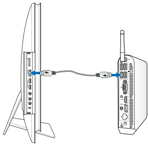
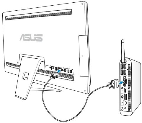
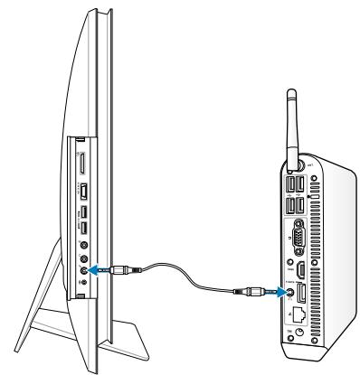
- Prepare a male-to-male USB cable. Connect one end of the USB cable to your laptop / desktop PC, and connect the other end of the cable to the E-SATA + USB 2.0 Combo port on the side of your All-in-one PC.
- If your laptop / desktop PC supports HDMI, prepare a male-to-male HDMI cable. Connect one end of the HDMI cable to your laptop / desktop PC, and connect the other end of the cable to the HDMI-input port on the rear side of the All-in-one PC.
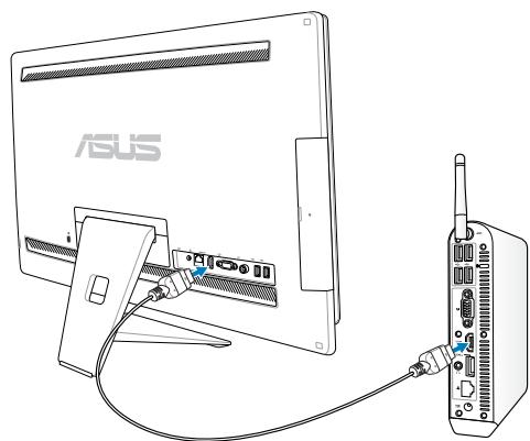
- If your laptop / desktop PC has no HDMI support, prepare a male-to-male VGA cable and a male-to-male stereo audio cable. Connect one end of the VGA cable and audio cable to your laptop / desktop PC, and connect the other end of the VGA cable to the Display-input port on the rear side of the All-in-one PC, and the other end of the audio cable to the microphone jack on the side of the All-in-one PC.
- An Input Select OSD menu appears when you connect the HDMI or VGA cable to the rear HDMI-input or Display-input port. Use the Volume Increase (↑) / Decrease (↓) buttons to select HDMI with Device Share or VGA with Device Share press the MENU button to activate the option.

- The Device Share function supports a Microsoft Windows®-based laptop / desktop PC only.
- By default, your All-in-one PC is set to PC mode (All-in-one PC is the display input source). The touch screen, webcam and rear USB ports will be controlled by the All-in-one PC even if the Device Share function is enabled.
- When switching the display input source to HDMI or VGA (using your All-in-one PC as a desktop LCD monitor), the touch screen, webcam and rear USB ports will be controlled by the external laptop / desktop PC if the Device Share function is enabled.
- When using the Device Share function, it is strongly recommended to connect ONLY a USB mouse or keyboard to the rear USB ports. External USB storage devices are not recommended.
- The Device Share function can be activated even if your All-in-one PC is not powered-on. If you power on your All-in-one PC while using the Device Share function, an Input Select OSD menu will appear for display signal selection.
Configuring a wireless connection
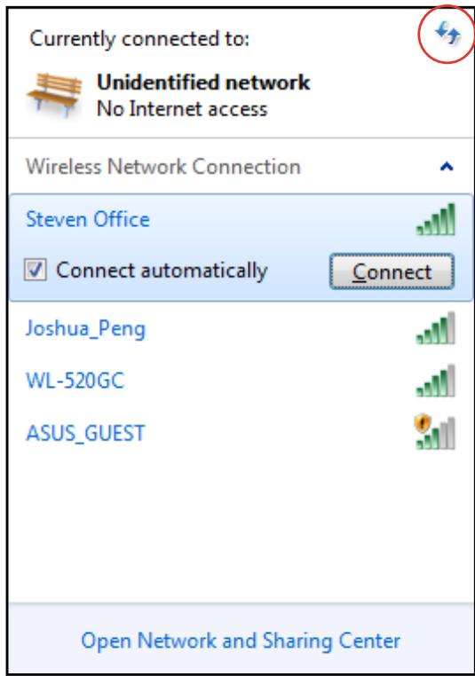
- Click the wireless network icon with an orange star in the Windows® Notification area.
- Select the wireless access point you want to connect to from the list and click Connect to build the connection.

If you cannot find the desired access point, click the Refresh icon on the upper right corner to refresh and search in the list again.

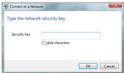
Enter the network security key when connecting to a security-enabled network.
- After a connection has been established, the connection is shown on the list.
- You can see the wireless network icon in the Notification area.
Configuring a wired connection
Using a static IP
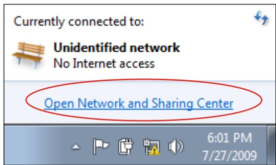
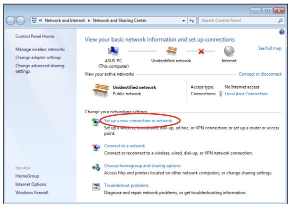
- Click the network icon with a yellow warning triangle in the Windows® Notification area and select Open Network and Sharing Center.

Ensure that you have connected the LAN cable to the All-in-one PC.
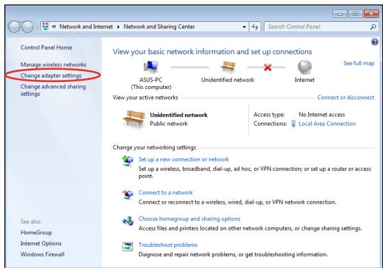
- Click Change adapter settings in the left panel.
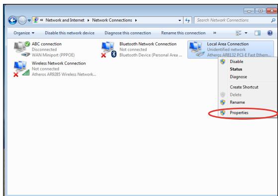
- Right-click Local Area Connection and select Properties.
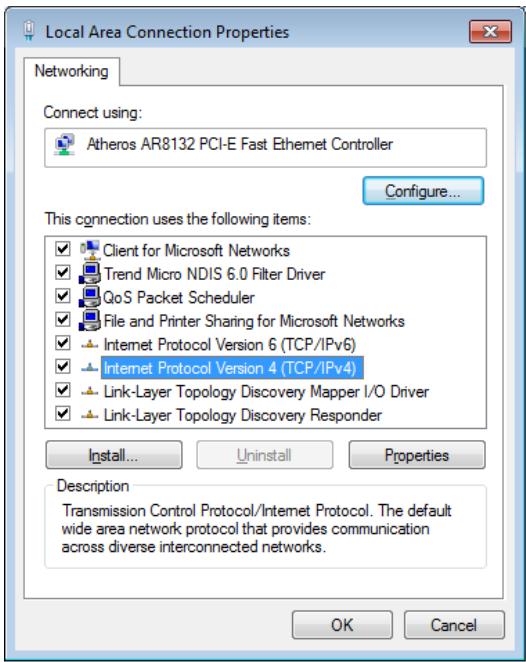
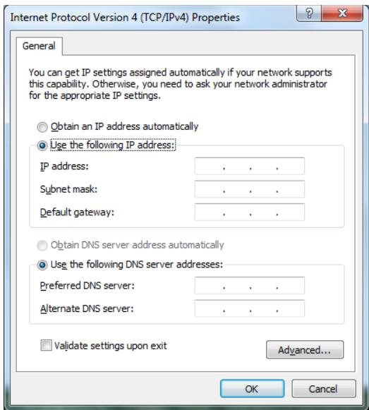
- Click Internet Protocol Version 4(TCP/ IPv4) and click Properties.
- Select Use the following IP address.
- Enter your IP address, Subnet mask, and Default gateway.
- If needed, enter the Preferred DNS server address.
- After entering all the related values, click OK to finish the configuration.
Using a dynamic IP (PPPoE)
- Repeat steps 1-4 in the previous section.
2 Select Obtain an IP address automatically and click OK.
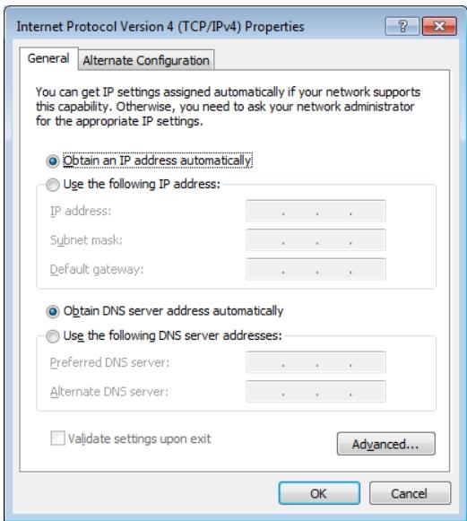
(Continue the following steps if using PPPoE)
- Return to the Network and Sharing Center and then click Set up a new connection or network.
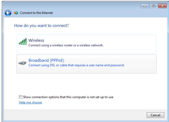
- Select Connect to the Internet and click Next.
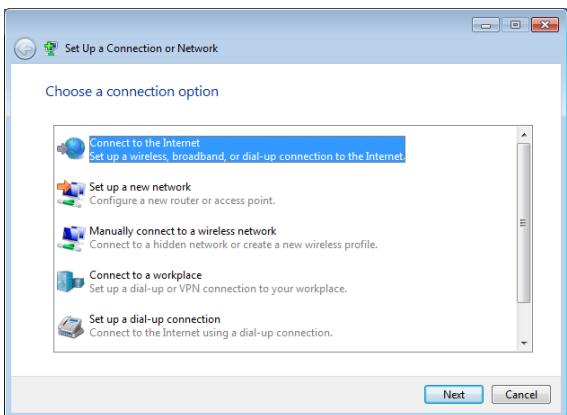
- Select Broadband (PPPoE) and click Next.
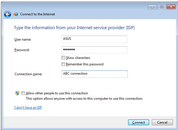
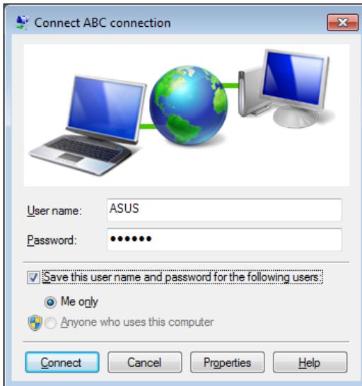
- Enter User name, Password, and Connection name. Click Connect.
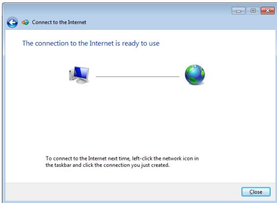
- Click Close to finish the configuration.
- Click the network icon in the notification area and click the connection you just created.
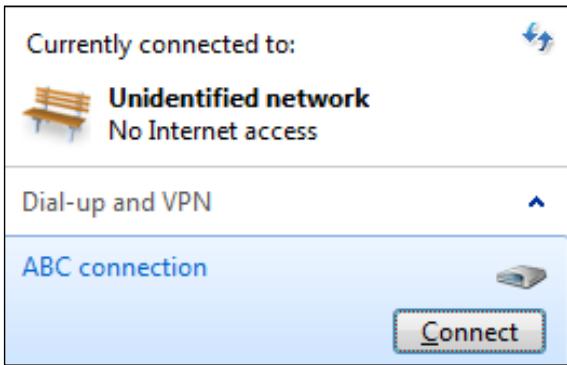
- Enter your user name and password. Click Connect to connect to the Internet.
Connecting to external audio devices
In addition to built-in stereo speakers (2-channel, left-right speakers), All-in-one PC allows you to use external audio devices. Refer to the table below for the audio jacks on the left panel and their functions.
| Audio jack | Description |
| Audio Out; Connects to headphones. | |
| Mic In; Connects to microphone | |
| (( )) | Connects to ASUS All-in-one PC subwoofer (optional) |

The subwoofer jack can ONLY be connected to All-in-one PC subwoofoers or sound devices by ASUS. DO NOT connect other devices to this jack. Doing so may damage the device.
Configuring audio output settings
After connecting a speaker system to your All-in-one PC, follow the steps below to configure the speaker settings:
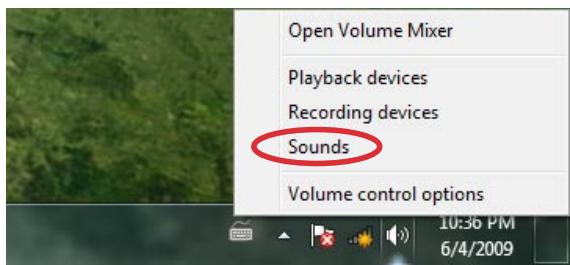
- Right-click the speaker icon in the Windows® notification area and click Sounds.
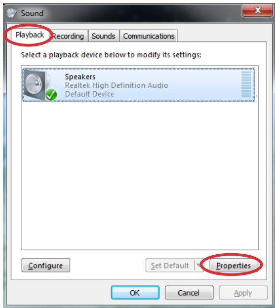
- Select a playback device and click Properties to configure the settings.
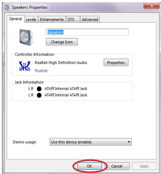
- Do the advanced configurations, such as adjusting the speaker level and output rate. Click OK to finish the configurations.
Recovering your system
Using the hidden partition
The recovery partition includes an image of the operating system, drivers, and utilities installed on your system at the factory. The recovery partition provides a comprehensive recovery solution that quickly restores your system's software to its original working state, provided that your hard disk drive is in good working order. Before using the recovery partition, copy your data files (such as Outlook PST files) to a USB device or to a network drive and make note of any customized configuration settings (such as network settings).
Recovering the OS to the Factory Default Partition (F9 Recovery)
- Press [F9] during bootup.
- Select Windows setup [EMS Enabled] when this item appears and press [Enter].
- Select the language and click Next.
- Select Recover the OS to the Default Partition and click Next.
- The factory default partition will be displayed.Click Next.
- Data on the default partition will be cleared. Click Recover to start the system recovery.

You will lose all your data on the selected partition. Ensure to back up your important data beforehand.
- When the recovery is completed successfully, click Reboot to restart the system.
Backing up the Factory Default Environment Data to a USB Drive (F9 Backup)
- Repeat the step 1-3 in the previous section.
- Select Backup the Factory Environment to a USB Drive and click Next.
- Connect a USB storage device to your PC to start the Factory Default Environment backup.

The required size of the connected USB storage device should be larger than 5GB. The actual size may vary with your PC model.
- Select a desired USB storage device if more than one USB storage device is connected to your All-in-one PC and click Next.

If there is already a partition with proper size in the selected USB storage device (for example, a partition that has been used as the backup partition), the system will show this partition automatically and reuse it for backup.
- Based on the different situations in the previous step, data on the selected USB storage device or on the selected partition will be cleared. Click Backup to start backup.

You will lose all your data on the selected USB storage device or on the selected partition. Ensure to back up your important data beforehand.
- When backing up the factory default environment is completed successfully, click Reboot to restart the system.
Using the USB storage device (USB Restore)
When the Recovery Partition in your system is crashed, use the USB storage device to restore the system to the factory default partition or the factory environment data to the entire hard disk.
- Connect the USB storage device that you back up the factory environment data to.
- Press
on bootup and the Please select boot device screen appears. Select USB:XXXXXX to boot from the connected USB storage device. - Select the language and click Next.
- Select Restore and click Next.
- Select a task and click Next. Task options:
- Restore the OS to the Default Partition only
Select this option if you simply want to restore the OS to the factory default partition. This option deletes all data on the system partition "C" and keeps the partition "D" unchanged. After you click Next, the factory default partition will be displayed. Click Next again.
- Restore the Whole Hard Disk
Select this option if you want to restore your All-in-one PC to the factory default state. This option deletes all data from your hard disk and creates a new system partition as drive "C", an empty partition as drive "D" and a Recovery Partition.
- Data on the factory default partition or on the whole hard disk will be cleared depending on the option you selected in the previous step. Click Restore to start the task.
- When the restore is completed successfully, click Reboot to restart the system.
| Manufacturer | ASUSTek COMPUTER INC. |
| Address, City | No. 150, LI-TE RD., PEITOU, TAIPEI 112, TAIWAN R.O.C |
| Country | TAIWAN |
| Authorized Representative in Europe | ASUS COMPUTER GmbH |
| Address, City | HARKORT STR. 21-23, 40880 RATINGEN |
| Country | GERMANY |