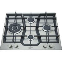
HP640VGT - Oven Freggia - Free user manual and instructions
Find the device manual for free HP640VGT Freggia in PDF.


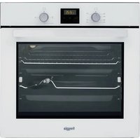
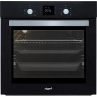
| Product Type | Built-in Electric Oven |
| Brand | Freggia |
| Model | HP640VGT |
| Energy Source | Electric |
| Overall Dimensions (H x W x D) | 595 x 595 x 575 mm |
| Built-in Dimensions (H x W x D) | 590 x 560 x 550 mm |
| Weight | 31 kg |
| Oven Capacity | 72 L |
| Power Consumption (Max) | 2400 W |
| Voltage | 220-240 V |
| Frequency | 50 Hz |
| Number of Functions | 8 |
| Main Functions | Conventional, Grill, Fan-assisted, Defrost, Pizza, Bottom heat, Top heat, Fan grill |
| Temperature Range | 50 °C to 250 °C |
| Control Type | Rotary knobs |
| Display | LED timer |
| Cleaning Type | Catalytic liners (back wall) |
| Safety Features | Child lock, Cool touch door, Auto shut-off |
| Door Type | Triple glazed, removable inner pane |
| Lighting | Halogen oven light (25 W) |
| Accessories Included | 1 wire shelf, 1 baking tray, 1 grill rack |
| Repairability Index | 7.0 / 10 |
| Spare Parts Availability | Heating elements, thermostat, knobs, glass door, seals |
| Energy Efficiency Class | A |
| Noise Level | < 50 dB |
Frequently Asked Questions - HP640VGT Freggia
User questions about HP640VGT Freggia
0 question about this device. Answer the ones you know or ask your own.
Ask a new question about this device
Download the instructions for your Oven in PDF format for free! Find your manual HP640VGT - Freggia and take your electronic device back in hand. On this page are published all the documents necessary for the use of your device. HP640VGT by Freggia.
USER MANUAL HP640VGT Freggia
Thank you for purchasing Freggia built-in hob.
Please carefully read the user manual, as it contains the instructions for the safe installation, operation and maintenance of the built-in hob.
Save it for future use.
RU
We invite you to read this instruction booklet carefully, before installing and using the equipment. It is very important that you keep this booklet together with the equipment for any future consultation. If this equipment should be sold or transferred to another person, make sure that the new user receives the booklet, so that he can learn how to operate the appliance and read the corresponding notice. This is a class 3 appliance.
This appliance complies with the following directives:

Declaration of conformity:
It declared that our products comply with current European directives, orders and regulations, and fulfill the conditions set out in the reference standards.
- The installation must be carried out by experienced and qualified personnel, in conformity with the regulations in force.
• This equipment has been designed to be used by adults.
- Therefore, make sure that children do not go near the equipment to play with it.
- While the appliance is running, watch the children and make sure they neither stay near the equipment, nor touch the surfaces that have not cooled down completely.
- Before powering the equipment, check that it is properly adjusted for the type of gas at disposal (see the "installation" paragraph).
- Before carrying out the maintenance or cleaning the equipment, cut power supply off and make it cool down.
- Make sure that air circulates around the gas equipment. Insufficient ventilation produces a lack of oxygen.
- In case of an intense or prolonged use of the equipment, it may be necessary to improve aeration, for example by opening a window or increasing the mechanical suction power, if it exists.
- The products of combustion must be discharged outside through a suction hood or an electric fan (see the "installation" paragraph).
- For any possible operation or modification, apply to an authorized Technical Assistance Centre and demand original spare parts.
WARNING: If the appli
If the appliance is equipped with a glass cover, the latter may shatter if heated. Turn off all the burners and wait a few minutes before closing the cover.
The product label, with the serial number, is sticked under the hob.
The manufacturer refuses all responsibility for possible damages to things or people, resulting from a wrong installation or from an improper, incorrect or unreasonable use of this equipment.
GENERAL NOTICE

1 Semi-rapid burner 1750W
2 Auxiliary burner 1000 W
3 Double ring burner 4000W
4 Control knob for burner
TECHNICAL CHARACTERISTIC TABLE
| BURNERS | GAS | NORMAL PRESSURE mbar | NORMAL RATE | INJECTOR DIAMETER 1/100 mm | TAPE BY PASS DIAMETER 1/100 mm | NOMINAL HEAT INPUT (W) | |||
| N° | DESCRIPTIONS | g/h | L/h | Max. | Min. | ||||
| 1 | SEMI-RAPID | G30-G31 | 28-30/37 | 127 | - | 67 | 31 | 1750 | 600 |
| G20 | 20 | - | 167 | 103 | Reg. | 1750 | 600 | ||
| 2 | AUXILIARY | G30-G31 | 28-30/37 | 73 | - | 50 | 27 | 1000 | 450 |
| G20 | 20 | - | 95 | 78 | Reg. | 1000 | 450 | ||
| 3 | DOUBLE RING | G30-G31 | 28-30/37 | 291 | - | 45(int)-69(ext) | 60 | 4000 | 2300 |
| G20 | 20 | - | 381 | 68(int)-101(ext) | Reg. | 4000 | 2300 | ||
Short title or reference to the measurement and calculation methods used to establish compliance with the above requirements.
The performance of each individual burner is calculated according to standard EN 30-2-1 (2015)
The total efficiency of the hob is calculated according to the EU Regulation 66/2014 Par. 2.2
The efficiency is calculated only for the burners with a nominal capacity exceeding 1,16 KW (EN 30-2-1 (2015)).
Information which is relevant to the customer to minimize the energy consumption during usage:
Energy Saving Tips:
- Use pots having flat base, - Use pots with proper size,
- Use pots with lid, minimize the amount of liquid or fat, when liquid starts boiling reduce the setting.
| MODEL IDENTIFICATION | HP640VGT |
| Type of hob | GAS BUILT IN HOBS |
| Number of cooking zones and/or areas | 4 |
| Heating technology | GAS |
| POSITION BURNER TYPE BURNER ENERGY EFFICIENCY FOR GAS BURNER | ||||
| Central Front Auxiliary | EE | gas burner | ** | % |
| Left Central | Semi Rapid | EEgas\ burner | 65,9 | % |
| Central Rear | Semi Rapid | EEgas\ burner | 65,9 | % |
| Right Central | Double Ring | EEgas\ burner | 59,2 | % |
| Energy efficiency for the gas hob | EEgas\ hob | 63,7 | % | |
TECHNICAL CHARACTERISTIC TABLE
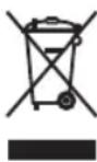
Fig. A
This product complies with Directive 2012/19/EU(WEEE).
This informative note is addressed exclusively to owners of devices that present the symbol of Fig. A in the adhesive label showing the technical data applied on the product itself (matricular label): This symbol indicates that the product is classified according to current regulations, as electrical or electronic equipment and e Complies with Directive 2012/19 / EU (WEEE) therefore, at the end of its own useful life, must be treated separately from household waste, delivering it for free at a separate collection point for equipment electrical and electronic products or returning it to the dealer when buying a new equivalent device.
The user is responsible for placing the appliance at the end of its life at the appropriate collection facilities, under penalty of the penalties provided for by the current waste legislation.
Appropriate separate waste collection for the subsequent start-up of the disposed appliance to recycling, treatment and environmentally compatible disposal helps to avoid possible negative effects on the environment and on health and favors the recycling of the materials of which the product is composed. For more detailed information regarding the collection systems available, contact the local waste disposal service, or the store where the purchase was made.
Manufacturers and importers comply with their responsibility for environmentally compatible recycling, treatment and disposal either directly or by participating in a collective scheme.
The manufacturing firm refuses all responsibility for any possible imprecision in this booklet, due to misprints or clerical errors. It reserves the right to make all the changes that it will consider necessary in its own products, without effecting the essential characteristics of functionality and safety.
INSTRUCTIONS FOR THE USER
It is necessary that all the operations regarding the installation, adjustment and adaptation to the type of gas available are carried out by qualified personnel, in conformity with the regulations in force.
The specific instructions are described in the booklet section intended for the installer.
USING THE BURNERS
The symbols silk-screen printed on the side of the knob indicate the correspondence between the knob and the burner.
• START-UP WITHOUT VALVES
Turn the corresponding knob anticlockwise up to the maximum position (large flame, fig. 1) and press the knob P (fig. 1).
• AUTOMATIC START-UP WITH VALVES
Turn the corresponding knob anticlockwise up to the maximum position (large flame, fig. 1) and press the knob. Once the burner has been started up, keep the knob pressed for about 6 seconds.
• USING THE BURNERS
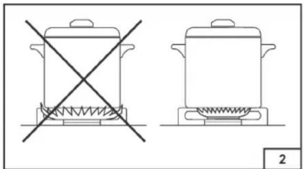
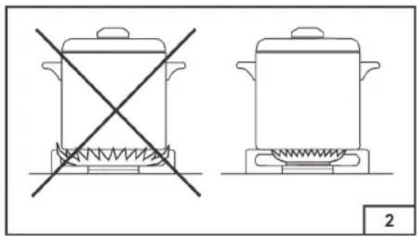
In order to obtain the maximum yield without waste of gas, it is important that the diameter of the pot is suitable for the burner potential (see the following table), so as to avoid that the flame goes out of the pot bottom (fig. 2).
Use the maximum capacity to quickly make the liquids reach the boiling temperature, and the reduced capacity to heat food or maintain boiling. All of the operating positions must be chosen between the maximum and the minimum ones, never between the minimum position and the closing point.
| BURNERS POWER (W) ∅ of pots | |
| Auxiliary 1000 10 - 14 cm | |
| Semi-rapid 1750 16 - 18 cm | |
| Semi-rapid 1750 16 - 18 cm | |
| Double ring 4000 22 - 24 cm |
Use the maximum capacity to quickly make the liquids reach the boiling temperature, and the reduced capacity to heat food or maintain boiling. All of the operating positions must be chosen between the maximum and the minimum ones, never between the minimum position and the closing point.
The gas supply can be interrupted by turning the knob clockwise up to the closing position.
If there is no power supply, it is possible to light the burners with matches, setting the knob to the start-up point (large flame, fig. 1).
• NOTICE
- When the equipment is not working, always check that the knobs are in the closing position (see fig.1).
- If the flame should blow out accidentally, the safety valve will automatically stop the gas supply, after a few seconds. To restore operation, set the knob to the lighting point (large flame, fig. 1) and press.
- While cooking with fat or oil, pay the utmost attention as these substances can catch fire when overheated.
- Do not use sprays near the appliance in operation.
• Do not place unstable or deformed pots on the burner, so as to prevent them from overturning or overflowing. - Make sure that pot handles are placed properly.
- When the burner is started up, check that the flame is regular and, before taking pots away, always lower the flame or put it out.
INSTRUCTIONS FOR THE USER
CLEANING
Before any operation, disconnect the appliance from the electric grid.
Don't use a steam cleaner for the cleaning the hob.
It is advisable to clean the appliance when it is cold.
• ENAMELLED PARTS
The enamelled parts must be washed with a sponge and soapy water or with a light detergent.
Do not use abrasive or corrosive products.
Do not leave substances, such as lemon or tomato juice, salt water, vinegar, coffee and milk on the enamelled surfaces for a long time.
• STAINLESS STEEL PARTS
Stainless steel can be stained if it remains in contact with highly calcareous water or aggressive detergents for an extended period of time.
The stainless steel parts should also be cleaned with soapy water and then dried with a soft cloth.
• BURNERS AND RACKS
These parts can be removed to make cleaning easier.
The burners must be washed with a sponge and soapy water or with a light detergent, wiped well and placed in their housing perfectly. Make sure that the flame-dividing ducts are not clogged.
Check that the feeler of the safety valve and the start-up electrode are always perfectly cleaned, so as to ensure an optimum operation.

Warning!
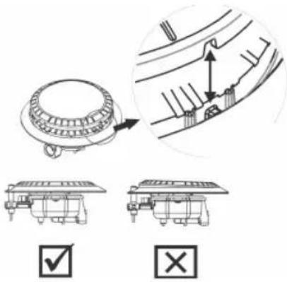
After cleaning the burner, make sure that the lid is placed in the housing.

The 2 reference cuts must be entered on the 2 references made on the flame retardant (see the arrows drawn in the burner and lid).

Warning!
The burner cap must be positioned steadily and flat.
• GASTAPS
The possible lubrication of the taps must be carried out by specialized personnel, exclusively.
In case of hardening or malfunctions in the gas taps, apply to the Customer Service.
INSTRUCTIONS FOR THE INSTALLER
IMPORTANT NOTICE:
THE OPERATIONS INDICATED BELOW MUST BE FOLLOWED BY QUALIFIED PERSONNEL EXCLUSIVELY, IN CONFORMITY WITH THE REGULATIONS IN FORCE. THE MANUFACTURING FIRM REFUSES ALL RESPONSIBILITY FOR DAMAGES TO PEOPLE, ANIMALS OR THINGS, RESULTING FROM THE FAILURE TO COMPLY WITH SUCH PROVISIONS.
INSTALLATION
Attention!
The installation must be performed in conformity with current regulations.
• INSTALLING THE TOP
The appliance is designed to be embedded into heat-resistant pieces of furniture.
The walls of the pieces of furniture must resist a temperature of 75° C besides the room one.
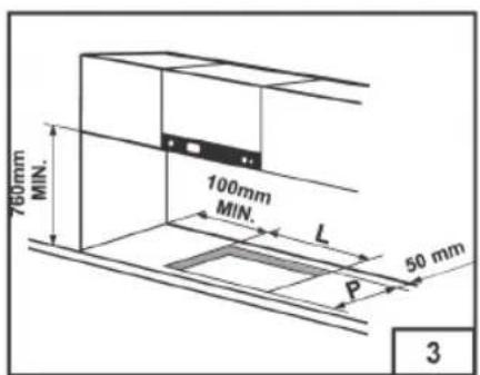
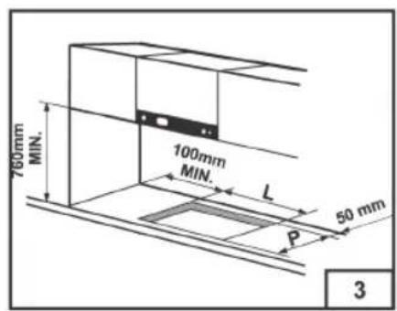
The equipment must not be installed near inflammable materials, such as curtains, cloths, etc. Make a hole in the top of the piece of furniture, with the dimensions indicated in fig. 3, at a distance of at least 50 mm from the appliance border to the adjacent walls.
| MODEL L (mm) | P (mm) | |
| HP640VGT 560 | 480 |
(*) Necessary size for the installation with cover.
Any possible wall unit over the cook-top must be placed at a distance of at least 760 mm from the top.
It is advisable to isolate the appliance from the piece of furniture below with a separator, leaving a depression space of at least 10 mm (fig. 4).
If the hob is going to be installed on the top of an oven, precautions must be taken to guarantee an installation in accordance with current accident prevention standards. Pay particular attention to the position of the electric cable and gas pipe: they must not touch any hot parts of the oven.
Moreover, if the hob is going to be installed on the top of a built in oven without forced cooling ventilation, proper air vents must be installed to guarantee an adequate ventilation, with the lower air entering with a cross section of at least 200cm2 , and the higher air exiting with a cross section of at least 60cm2 .
• FASTENING THE TOP
Every cook-top is equipped with a special washer. A set of hooks is also supplied for mounting the cook-top.
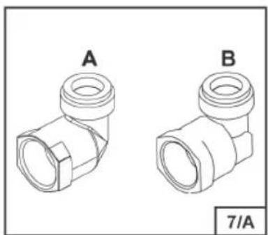
Depending on the type of mounting surface, the suitable type of mounting hook is supplied (hook A or hook B).
For the installation proceed as follows:
- Remove the racks and burners from the top.
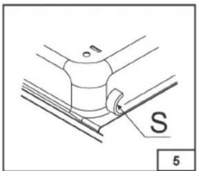
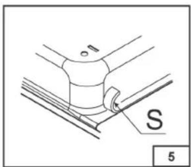
- Turn the appliance upside down and lay the washer S along the external border (fig. 5).
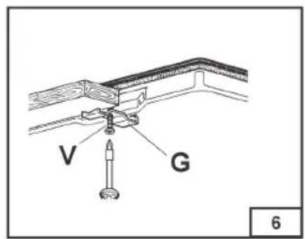
- Introduce and place the cook-top in the hole made in the piece of furniture, then block it with the V screws of the fastening hooks G (fig.6).
• INSTALLATION ROOM
This appliance is not provided with a device for exhausting the products of combustion.
Regarding room ventilation rules where appliance is installed make reference to the legislation, in conformity with the local regulations.
The room where the appliance is installed must have a minimum volume of 20m3 .
ATTENTION:
The electrical connection of the cooking hob and the oven must be carried out separately for security issues and to allow easy removal of the oven from the unit.
INSTRUCTIONS FOR THE INSTALLER
• FOR THE U.K. ONLY
The room containing this hotplate should have an air supply in accordance with BS 5440: Part 2: 1989.
- All rooms require an openable window, or equivalent and some rooms will require a permanent vent a well.
- For room volumes up to 5m 3 an air vent of 100cm 2 is required.
- For room volumes between 5m 3 and 10m 3 an air vent of 50cm 2 is required.
- If the room is greater than 5m 3 and has a door that opens directly to the outside, then no air vent is required.
If there are other fuel burning appliances in the same room BS 5440: Part 2:1989 should be consulted to determine the air vent requirements.
• GAS CONNECTION
Choose fixed connections or use a flexible pipe in stainless steel in compliance with the regulation in force.
If you use flexible metallic pipes, be careful they do not come in touch with mobile parts or they are not squeezed. Also be careful when the hob is put together with an oven.

ATTENTION: Make sure that the gas supply pressure of the appliance obeys the recommended values If the supplied pressure has not the specified value, it is necessary to assemble a proper pressure regulator in compliance with the standard UNI EN 88.
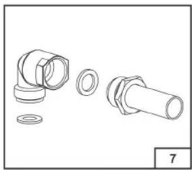
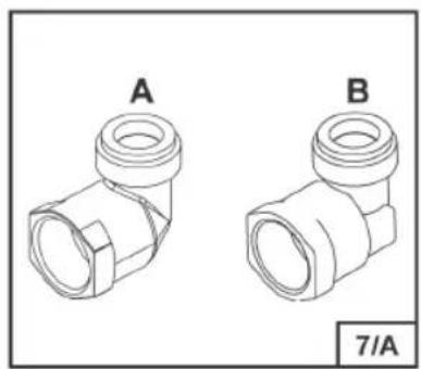
For Liquid Gas (LPG) the use of pressure regulator is allowed only if they are in compliance with UNI EN 12864. The adjustable connection is fixed to the comprehensive ramp by means of a threaded nut G 1/2». Screw the parts without force, adjust the connection inthe necessary direction and tighten everything (fig.7-7/A).
Rigid connection
Carry out connection by using metal rigid pipes (copper with mechanical end) (UNI-CIG 7129).
Flexible connection
Use a flexible pipe in stainless steel (UNI-CIG 9891) with a maximum length 2m.
When installation is complete, make sure that the seal of each pipe fitting is correct.
Use a soapy solution, not a flame.
• ELECTRIC CONNECTION
The connection to the electric grid must be carried out by qualified personnel and in conformity with the regulations in force.
The voltage of the electric system must correspond to the value indicated in the label under the appliance. Make sure that the electric system is provided with an effective ground connection in compliance with the regulations and provisions of the law. Grounding is compulsory.
This device must be at a suitable opening distance from the contacts in order to allow the entire disconnection in case of overvoltage category III, in accordance with installation rules.
GAS TRANSFORMATIONS AND ADJUSTMENTS
• REPLACING THE NOZZLES
If the equipment is adjusted for a type of gas that is different from the one available, it is necessary to replace the burner nozzles.
The choice of the nozzles to replace must be made according to the table of the "technical characteristics" as enclosed.
INSTRUCTIONS FOR THE INSTALLER
Act as follows:
- Remove the racks and burners.
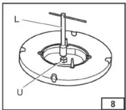
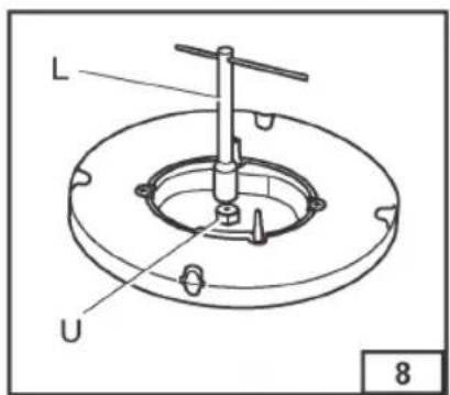
- By means of a straight spanner L, unscrew the nozzle U (fig.8) and substitute it with the corresponding one.
- Tighten the nozzle strongly.
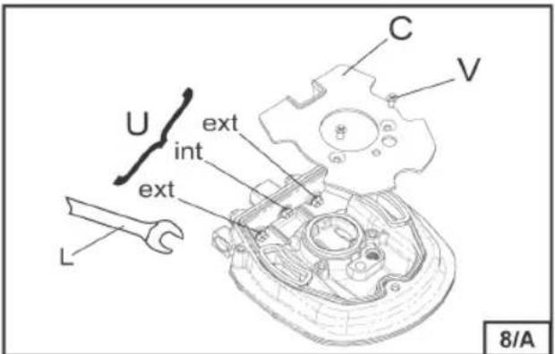
• DOUBLE CROWN BURNER: (Fig. 8/A)
- Unscrew the screws (V) and remove the cover (C);
- Unscrew the injector with a English wrench (L)
- Fit the corresponding gas injectors (U) instead, in accordance with the marking of the injectors and the gas characteristics table.
• Block the injectors vigorously.
• Fit the cover (C) and tighten the screws
• ADJUSTING THE BURNERS
The lowest flame point must always be properly adjusted and the flame must remain on even if there is an abrupt shift from the maximum to the minimum position.
If this is not so, it is necessary to adjust the lowest flame point as follows:
- start the burner up
- turn the tap up to the minimum position (small flame)
- remove the knob from the tap rod
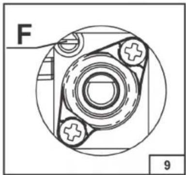
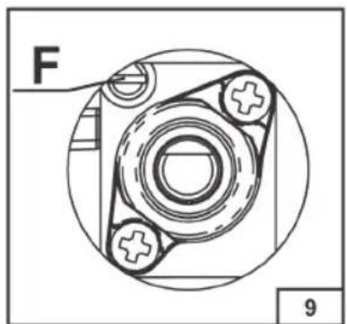
- introduce a flat-tip screwdriver in the hole F of the tap (fig. 9) and turn the by-pass screw up to a proper adjustment of the lowest flame point.
As regards G30 gas burners, the by-pass screw must be tightened completely.
MAINTENANCE
• REPLACING THE POWER SUPPLY CABLE
If the power supply cable should be replaced, it is necessary to use a cable with a section of 3 × 0.75 mm2 , type H05V2V2-F or H05RR-F, complying with the regulations in force for the hob with gas burners. For the hob with electric plates and power under 1500W 3 × 1 mm2 power cable should be used.
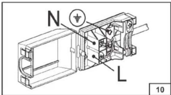
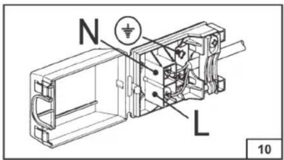
The connection to the terminal board must be effected as shown in fig. 10:
brown cable L (phase)
blue cable N (neutral)
green-yellow cable (ground)
If the supply cord is damaged, it must be replaced by the manufacturer, its service agent or similarly qualified persons in order to avoid a hazard.
The manufacturing firm refuses all responsibility for any possible imprecision in this booklet, due to misprints or clerical errors. It reserves the right to make all the changes that it will consider necessary in its own products, without effecting the essential characteristics of functionality and safety.





ЗАГАЛЬНА ІНФОРМАЦІЯ

Увага!





INSTRUKCJA I WSKAZÓWKI DO INSTALACJI, OBSŁUGI I KONSERWACJI PŁYT KUCHENNYCH DO ZABUDOWY
Szanowni Państwo,
INSTRUKCJE DLA INSTALATORA





_
| _
一
1
FOR YEARS TO COME freggia

This manual can be downloaded at www.freggia.com


- RU
- DECLARATION OF CONFORMITY
- WARNING: IF THE APPLI
- GENERAL NOTICE
- TECHNICAL CHARACTERISTIC TABLE
- THIS PRODUCT COMPLIES WITH DIRECTIVE 2012/19/EU(WEEE)
- INSTRUCTIONS FOR THE USER
- USING THE BURNERS
- START-UP WITHOUT VALVES
- AUTOMATIC START-UP WITH VALVES
- NOTICE
- CLEANING
- ENAMELLED PARTS
- STAINLESS STEEL PARTS
- BURNERS AND RACKS
- GASTAPS
- INSTRUCTIONS FOR THE INSTALLER
- IMPORTANT NOTICE
- INSTALLATION
- ATTENTION
- INSTALLING THE TOP
- (*) NECESSARY SIZE FOR THE INSTALLATION WITH COVER
- FASTENING THE TOP
- INSTALLATION ROOM
- FOR THE U.K. ONLY
- GAS CONNECTION
- RIGID CONNECTION
- FLEXIBLE CONNECTION
- ELECTRIC CONNECTION
- GAS TRANSFORMATIONS AND ADJUSTMENTS
- REPLACING THE NOZZLES
- ACT AS FOLLOWS
- DOUBLE CROWN BURNER: (FIG. 8/A)
- ADJUSTING THE BURNERS
- MAINTENANCE
- REPLACING THE POWER SUPPLY CABLE
- THE CONNECTION TO THE TERMINAL BOARD MUST BE EFFECTED AS SHOWN IN FIG. 10
- ЗАГАЛЬНА ІНФОРМАЦІЯ
- INSTRUKCJA I WSKAZÓWKI DO INSTALACJI, OBSŁUGI I KONSERWACJI PŁYT KUCHENNYCH DO ZABUDOWY
- INSTRUKCJE DLA INSTALATORA
- FOR YEARS TO COME FREGGIA
Brand : Freggia
Model : HP640VGT
Category : Oven