Mio Modero R-2 - Controller AMX - Free user manual and instructions
Find the device manual for free Mio Modero R-2 AMX in PDF.

| Product Type | Controller |
| Brand | AMX |
| Model | Mio Modero R-2 |
| Dimensions (W x H x D) | 4.0 x 2.0 x 1.2 inches |
| Weight | 0.5 lbs |
| Power Supply | 12 V DC, 1.5 A |
| Power Consumption | 5 W (max) |
| Main Functions | Programmable control of audio/video equipment, touchscreen interface, IR and serial control, Ethernet connectivity |
| Connectivity | Ethernet (RJ-45), IR emitter, RS-232, USB |
| Display | 2.8-inch color touchscreen |
| Operating Temperature | 32°F to 104°F (0°C to 40°C) |
| Maintenance & Cleaning | Wipe with a soft, dry cloth; do not use liquids or abrasives |
| Safety Precautions | Avoid exposure to moisture, extreme temperatures, and physical shock |
| Spare Parts & Repairability | Contact AMX authorized service centers for parts and repairs |
| General Information | Part of the Mio Modero series, designed for professional AV control systems |
Frequently Asked Questions - Mio Modero R-2 AMX
User questions about Mio Modero R-2 AMX
0 question about this device. Answer the ones you know or ask your own.
Ask a new question about this device
Download the instructions for your Controller in PDF format for free! Find your manual Mio Modero R-2 - AMX and take your electronic device back in hand. On this page are published all the documents necessary for the use of your device. Mio Modero R-2 by AMX.
USER MANUAL Mio Modero R-2 AMX
Operation/Reference Guide
Mio Modero® R-2
Remote Control Device
AMX Limited Warranty and Disclaimer
AMX warrants its products to be free of defects in material and workmanship under normal use for three (3) years from the date of purchase from AMX, with the following exceptions:
- Electroluminescent and LCD Control Panels are warranted for three (3) years, except for the display and touch overlay components that are warranted for a period of one (1) year.
- Disk drive mechanisms, pan/tilt heads, power supplies, and MX Series products are warranted for a period of one (1) year.
- AMX Lighting products are guaranteed to switch on and off any load that is properly connected to our lighting products, as long as the AMX Lighting products are under warranty. AMX does guarantee the control of dimmable loads that are properly connected to our lighting products. The dimming performance or quality cannot be guaranteed due to the random combinations of dimmers, lamps and ballasts or transformers.
- Unless otherwise specified, OEM and custom products are warranted for a period of one (1) year.
- AMX Software is warranted for a period of ninety (90) days.
- Batteries and incandescent lamps are not covered under the warranty.
This warranty extends only to products purchased directly from AMX or an Authorized AMX Dealer.
All products returned to AMX require a Return Material Authorization (RMA) number. The RMA number is obtained from the AMX RMA Department. The RMA number must be clearly marked on the outside of each box. The RMA is valid for a 30-day period. After the 30-day period the RMA will be cancelled. Any shipments received not consistent with the RMA, or after the RMA is cancelled, will be refused. AMX is not responsible for products returned without a valid RMA number.
AMX is not liable for any damages caused by its products or for the failure of its products to perform. This includes any lost profits, lost savings, incidental damages, or consequential damages. AMX is not liable for any claim made by a third party or by an AMX Dealer for a third party.
This limitation of liability applies whether damages are sought, or a claim is made, under this warranty or as a tort claim (including negligence and strict product liability), a contract claim, or any other claim. This limitation of liability cannot be waived or amended by any person. This limitation of liability will be effective even if AMX or an authorized representative of AMX has been advised of the possibility of any such damages. This limitation of liability, however, will not apply to claims for personal injury.
Some states do not allow a limitation of how long an implied warranty last. Some states do not allow the limitation or exclusion of incidental or consequential damages for consumer products. In such states, the limitation or exclusion of the Limited Warranty may not apply. This Limited Warranty gives the owner specific legal rights. The owner may also have other rights that vary from state to state. The owner is advised to consult applicable state laws for full determination of rights.
EXCEPT AS EXPRESSLY SET FORTH IN THIS WARRANTY, AMX MAKES NO OTHER WARRANTIES, EXPRESSED OR IMPLIED, INCLUDING ANY IMPLIED WARRANTIES OF MERCHANTABILITY OR FITNESS FOR A PARTICULAR PURPOSE. AMX EXPRESSLY DISCLAIMS ALL WARRANTIES NOT STATED IN THIS LIMITED WARRANTY. ANY IMPLIED WARRANTIES THAT MAY BE IMPOSED BY LAW ARE LIMITED TO THE TERMS OF THIS LIMITED WARRANTY.
Software License and Warranty Agreement
LICENSE GRANT.
AMX grants to Licensee the non-exclusive right to use the AMX Software in the manner described in this License. The AMX Software is licensed, not sold. This license does not grant Licensee the right to create derivative works of the AMX Software. The AMX Software consists of generally available programming and development software, product documentation, sample applications, tools and utilities, and miscellaneous technical information. Please refer to the README.TXT file on the compact disc or download for further information regarding the components of the AMX Software. The AMX Software is subject to restrictions on distribution described in this License Agreement. LICENSEE MAY NOT SUBLICENSE, RENT, OR LEASE THE AMX SOFTWARE. Licensee may not reverse engineer, decompile, or disassemble the AMX Software.
INTELLECTUAL PROPERTY.
The AMX Software is owned by AMX and is protected by United States copyright laws, patent laws, international treaty provisions, and/or state of Texas trade secret laws. Licensee may make copies of the AMX Software solely for backup or archival purposes. Licensee may not copy the written materials accompanying the AMX Software.
TERMINATION.
AMX RESERVES THE RIGHT, IN ITS SOLE DISCRETION, TO TERMINATE THIS LICENSE FOR ANY REASON AND UPON WRITTEN NOTICE TO LICENSEE. In the event that AMX terminates this License, the Licensee shall return or destroy all originals and copies of the AMX Software to AMX and certify in writing that all originals and copies have been returned or destroyed.
PRE-RELEASE CODE.
Portions of the AMX Software may, from time to time, as identified in the AMX Software, include PRE-RELEASE CODE and such code may not be at the level of performance, compatibility and functionality of the final code. The PRE-RELEASE CODE may not operate correctly and may be substantially modified prior to final release or certain features may not be generally released. AMX is not obligated to make or support any PRE-RELEASE CODE. ALL PRE-RELEASE CODE IS PROVIDED "AS IS" WITH NO WARRANTIES.
LIMITED WARRANTY.
AMX warrants that the AMX Software will perform substantially in accordance with the accompanying written materials for a period of ninety (90) days from the date of receipt. AMX DISCLAIMS ALL OTHER WARRANTIES, EITHER EXPRESS OR IMPLIED, INCLUDING, BUT NOT LIMITED TO IMPLIED WARRANTIES OF MERCHANTABILITY AND FITNESS FOR A PARTICULAR PURPOSE, WITH REGARD TO THE AMX SOFTWARE. THIS LIMITED WARRANTY GIVES LICENSEE SPECIFIC LEGAL RIGHTS. Any supplements or updates to the AMX SOFTWARE, including without limitation, any (if any) service packs or hot fixes provided to Licensee after the expiration of the ninety (90) day Limited Warranty period are not covered by any warranty or condition, express, implied or statutory.
LICENSEE REMEDIES.
AMX's entire liability and Licensee's exclusive remedy shall be repair or replacement of the AMX Software that does not meet AMX's Limited Warranty and which is returned to AMX. This Limited Warranty is void if failure of the AMX Software has resulted from accident, abuse, or misapplication. Any replacement AMX Software will be warranted for the remainder of the original warranty period or thirty (30) days, whichever is longer. Outside the United States, these remedies may not available.
NO LIABILITY FOR CONSEQUENTIAL DAMAGES. IN NO EVENT SHALL AMX BE LIABLE FOR ANY DAMAGES WHATSOEVER (INCLUDING, WITHOUT LIMITATION, DAMAGES FOR LOSS OF BUSINESS PROFITS, BUSINESS INTERRUPTION, LOSS OF BUSINESS INFORMATION, OR ANY OTHER PECUNIARY LOSS) ARISING OUT OF THE USE OF OR INABILITY TO USE THIS AMX SOFTWARE, EVEN IF AMX HAS BEEN ADVISED OF THE POSSIBILITY OF SUCH DAMAGES. BECAUSE SOME STATES/COUNTRIES DO NOT ALLOW THE EXCLUSION OR LIMITATION OF LIABILITY FOR CONSEQUENTIAL OR INCIDENTAL DAMAGES, THE ABOVE LIMITATION MAY NOT APPLY TO LICENSEE.
U.S. GOVERNMENT RESTRICTED RIGHTS.
The AMX Software is provided with RESTRICTED RIGHTS. Use, duplication, or disclosure by the Government is subject to restrictions as set forth in subparagraph ©(1)(ii) of The Rights in Technical Data and Computer Software clause at DFARS 252.227-7013 or subparagraphs ©(1) and (2) of the Commercial Computer Software Restricted Rights at 48 CFR 52.227-19, as applicable.
SOFTWARE AND OTHER MATERIALS FROM AMX.COM MAY BE SUBJECT TO EXPORT CONTROL.
The United States Export Control laws prohibit the export of certain technical data and software to certain territories. No software from this Site may be downloaded or exported (i) into (or to a national or resident of) Cuba, Iraq, Libya, North Korea, Iran, Syria, or any other country to which the United States has embargoed goods; or (ii) anyone on the United States Treasury Department's list of Specially Designated Nationals or the U.S. Commerce Department's Table of Deny Orders. AMX does not authorize the downloading or exporting of any software or technical data from this site to any jurisdiction prohibited by the United States Export Laws.
This Agreement replaces and supersedes all previous AMX Software License Agreements and is governed by the laws of the State of Texas, and all disputes will be resolved in the courts in Collin County, Texas, USA. For any questions concerning this Agreement, or to contact AMX for any reason, please write: AMX, 3000 Research Drive, Richardson, TX 75082.
Table of Contents
Overview 1
The Mio Modero® R-2 1
Touch And Tilt Sensor 2
Specifications 2
FCC compliance 3
Mio R-2 Setup 5
Installing Your Custom Buttons.... 5
Inserting Batteries into The Mio R-2 5
Battery Low Indicator 5
Programming The Mio R-2 7
Using Connector Ports on The Mio R-2....7
IR/RF Code Matrix 8
Configuration Mode 9
IR Transmit Mode....9
Timeout Adjustment 9
Download Mode 10
Debug Mode.... 10
Battery Type 10
LED Awake Brightness.... 10
LED Sleep Mode Brightness 10
TeleText Mode.... 10
Updating Mio R-2 Firmware.... 11
Persistent Serial Commands 12
Mio Remote Charging Base 13
Specifications 14
Installing The Rechargeable Battery 15
Charging The Mio Remote with Charging Base 16
Changing Battery Modes 16
Configuration Mode 16
Battery Type.... 16
Table of Contents
Overview
The Mio Modero® R-2
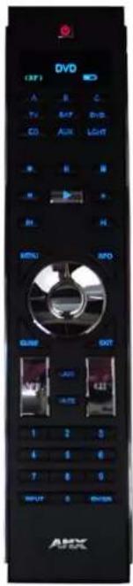
The Mio Modero® R-2 remote provides custom control features, contained in an elegant handheld rechargeable device. The Mio R-2 controls 6 different device modes, supports 3 macro functions, and is capable of executing 219 functions. The Mio R-2 can transmit in 38 KHz IR, 455 KHz IR, 418 RF (1-way) (FG147-418), 433 RF (1-way) (FG147-433), or 38 KHz and one of the RF frequencies.
Selecting a source device sends a command to the master and runs predetermined events associated with that source. Selecting a macro will run predefined events, which might not be associated with sources listed, then return the device to its previous mode.
You need KeypadBuilder to properly program this device. The application and documentation are available from www.amx.com.
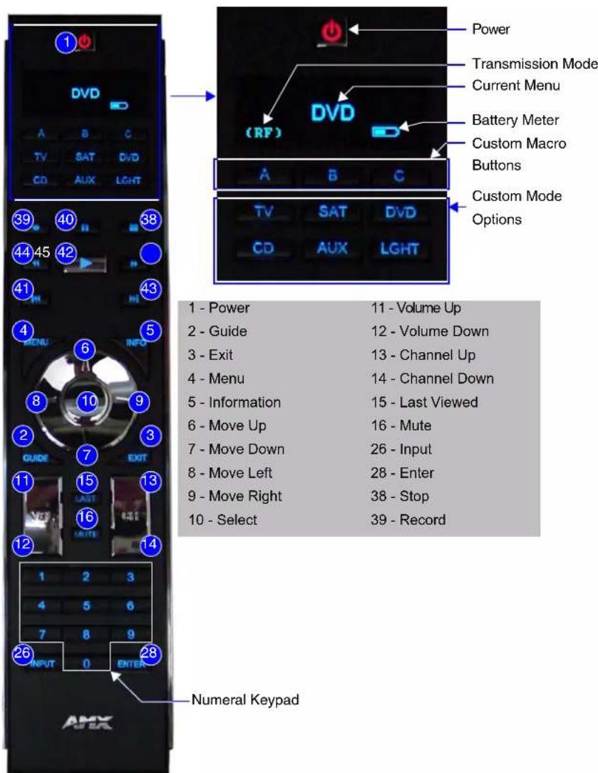
FIG. 1 The Mio R-2 Device
Touch And Tilt Sensor
The Mio R-2 wakes up upon touching either the chrome side rails or pressing a button. When holding the remote and it times out, you can reawaken the device by tilting it. Errant jostling such as a bumped table will not wake the device unless you are holding it.
Specifications
The Mio R-2 device specifications are as follows:
| Mio R-2 (FG147-418/433) Specifications | |
| Battery 4 AAA Alkaline Batteries (5 hours battery life) | |
| Transmission Frequencies | • AMX 38 KHz/455 KHz IR• 418 RF (1-way) (FG147-418)• 433 RF (1-way) (FG147-433) |
| Transmission Range (distance) with Mio IR Receiver | • 100 feet at 38KHz (IR)• 50 feet at 455KHz (IR)• 300 feet at 418 (RF)• 200 feet at 433 (RF) |
| Transmission Range (angle) | • 140 degrees (+/-70° from perpendicular) horizontally from an axis extending from the end of the remote. (IR)• 40 degrees (+/-20° from perpendicular) vertically from an axis extending from the end of the remote. (IR) |
| Top Components • LED | blue backlit buttons indicate device is awake• Display (OLED) - 128 x 32 pixels, active area is 29.42mm x 7.98mm• Pushbuttons - the power button is red backlit; the rest are blue backlit buttons. 45 buttons; 9 custom buttons (3 macro and 6 device). |
| Rear Component • Programming Port - 2.5 mm stereo female conductor jack• Battery Door• Rechargeable Battery Connection | |
| Dimensions (HWD) 9.50 x 2.00 x .74 (241.3 mm x 50.8 mm x 18.80 mm) | |
| Supported Languages: • English • Korean• French • Mandarin Chinese• German • Portuguese• Greek • Russian• Italian • Spanish• Japanese | |
| Weight • .45 lbs (20 kg) without batteries• .55 lbs (25 kg) with batteries | |
| Operating Environment: • Operating Temperature: 0° to 50° C (32° to 122° F)• Storage Temperature: -10° to 70° C (14° to 158° F) | |
| Other AMX Equipment • DB-9 extension cable (FG10-727)• Programming Cable - a 3 wire, 2.5 mm stereo jack (FG10-817)• Custom engraving (FG147-01)• Mio-RCC Kit (FG147-03K)• Mio-RCC Charging Base (FG147-02)• Mio-RBP Rechargeable Lithium Ion Battery (FG147-10)• AXR-RF 418 MHZ RF Receiver (FG782-418)• AXR-RF 433 MHZ RF Receiver (FG782-433) | |
FCC compliance
This device complies with Part 15 of the FCC rules. Subject to the following two conditions:
- This device must not cause harmful interference and
- This device must accept all interference, including interference that interferes with the operation of this device.
Changes or modifications not expressly approved by the party responsible for compliance could void the user's authority to operate the equipment.
Overview
Mio R-2 Setup
Installing Your Custom Buttons
-
Flip and turn the Mio R-2 device so that the buttons are facing away from you and the device is upside down.
-
Holding the device in both hands, place your thumbs on the battery door and push up to slide the battery door free.
-
Unscrew the 6 screw points indicated in FIG. 2.
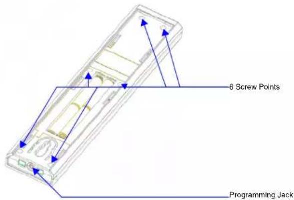
FIG. 2 Internal Mio R-2 Components
- Turn the unit over so the buttons are facing you.
- Lift the top assembly away from the PCB.
- If necessary, push out the standard buttons from the front of the top assembly.
- Drop on your custom button pad and verify the alignment with the guide posts on the PCB.
- Place the top assembly back down on the PCB and return the unit over, exposing the 6 screw points.
- Tighten the 6 screw points.
- Place the battery door back on the device, slide to lock it in place.
Inserting Batteries into The Mio R-2
To install your 4 AAA batteries into the Mio R-2 device:
- Flip and turn the Mio R-2 device so that the buttons are facing away from you and the device is upside down.
- Holding the device in both hands, place your thumbs on the battery door and slide the battery door free.
- Insert the batteries as indicated inside the battery compartment.
- Place the battery door back on the device, slide to lock it in place.
Battery Low Indicator
When the battery charge level is too low to sustain continuous operation, the LCD flashes, "Battery Low" and the device shuts down.
Mio R-2 Setup
Programming The Mio R-2
Most functionality of the Mio R-2 is handled using the application, KeypadBuilder. Go to www.amx.com for the KeypadBuilder Instruction Manual.
The Mio R-2 recognizes a select number of Serial Commands. For a full list and descriptions, consult the Persistent Serial Commands section on page 12.
Using Connector Ports on The Mio R-2
The programming jack is used for communication between the device and KeypadBuilder. The programming jack uses a three-wire, 2.5 mm stereo jack, you can order the programming cable (FG10-817) from AMX if you do not currently possess one. While loading your configuration file make sure the device is situated as such that the batteries will not fall out. The load will fail if your batteries fall out during the process. The Mio communicates at 115200 baud rate.
To download KeypadBuilder Configuration Files:
- Set the Mio R-2 Download mode to ON. See the Configuration Mode section for details.
- Flip and turn the Mio R-2 device so that the buttons are facing away from you and the device is upside down.
- Holding the device in both hands, place your thumbs on the battery door and slide the battery door free.
- Connect the 2.5 mm stereo plug (male) end of the programming cable (FG10-817) into the programming jack on the bottom side of the remote device.
- If necessary, connect the DB-9 end of the programming cable to the female DB-9 connector on the DB-9 extension cable (FG10-727).
-
Connect the female DB-9 terminal end of the extension cable to the port on the back of your computer.
-
Configure the communication parameters in KeypadBuilder.
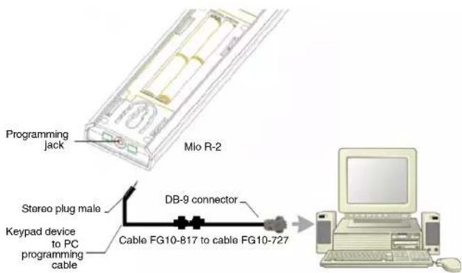
FIG. 3 Connecting The Keypad Device to Your PC
IR/RF Code Matrix
The IR/RF Code emitted depends upon which of the 6 configurable modes is selected. Below is the list of codes for each button within each mode.
IR/RF Code Matrix
| Button Label Mode | 1 | Mode 2 | Mode 3 | Mode 4 | Mode 5 | Mode 6 | |
| 1 Power Symbol 9 49 89 129 | 169 209 | ||||||
| 2 GUIDE 38 78 118 158 198 | 238 | ||||||
| 3 EXIT 37 77 117 157 197 237 | |||||||
| 4 MENU 31 71 111 151 191 | 231 | ||||||
| 5 INFO 39 79 119 159 199 239 | |||||||
| 6 ▲ | 32 72 112 152 192 | 232 | |||||
| 7 ▼ | 33 73 113 153 193 | 233 | |||||
| 8 ◀ | 34 74 114 154 194 | 234 | |||||
| 9 ▶ | 35 75 115 155 195 | 235 | |||||
| 10 | SELECT | 36 76 116 156 196 | 236 | ||||
| 11 | VOL + | 24 64 104 144 184 | 224 | ||||
| 12 | VOL - | 25 65 105 145 185 | 225 | ||||
| 13 | CH + | 22 62 102 142 182 | 222 | ||||
| 14 | CH - | 23 63 103 143 183 | 223 | ||||
| 15 | LAST | 40 80 120 160 200 | 240 | ||||
| 16 | MUTE | 26 66 106 146 186 | 226 | ||||
| 17 | 1 | 11 | 51 91 131 | 171 211 | |||
| 18 | 2 | 12 52 92 | 132 172 | 212 | |||
| 19 | 3 | 13 53 93 | 133 173 | 213 | |||
| 20 | 4 | 14 54 94 | 134 174 | 214 | |||
| 21 | 5 | 15 55 95 | 135 175 | 215 | |||
| 22 | 6 | 16 56 96 | 136 176 | 216 | |||
| 23 | 7 | 17 57 97 | 137 177 | 217 | |||
| 24 | 8 | 18 58 98 | 138 178 | 218 | |||
| 25 | 9 | 19 59 99 | 139 179 | 219 | |||
| 26 | INPUT 29 69 109 | 149 189 | 229 | ||||
| 27 | 0 | 10 50 90 | 130 170 | 210 | |||
| 28 | ENTER | 21 61 101 | 141 181 | 221 | |||
| 29 | A (Macro 1) | 250 250 | 250 250 | 250 250 | |||
| 30 | B (Macro 2) | 251 251 | 251 251 | 251 251 | |||
| 31 | C (Macro 3) | 252 252 | 252 252 | 252 252 | |||
| 32 | TV (Mode 1) | 241 241 | 241 241 | 241 241 | |||
| 33 | SAT (Mode 2) | 242 242 | 242 242 | 242 242 | |||
| 34 | DVD (Mode 3) | 243 243 | 243 243 | 243 243 | |||
| 35 | CD (Mode 4) | 244 244 | 244 244 | 244 244 | |||
| 36 | AUX (Mode 5) 245 | 245 245 245 | 245 245 | 245 | |||
| 37 | LIGHT (Mode 6) | 246 246 | 246 246 | 246 246 | |||
| 38 | STOP ■ | 2 | 42 | 82 | 122 | 162 | 202 |
| 39 | REC ● | 8 48 88 | 28 168 208 | ||||
| 40 | PAUSE II | 3 | 43 | 83 | 123 | 163 | 203 |
| IR/RF Code Matrix (Cont.) | |||||||
| Button Label Mode | 1 | Mode 2 | Mode 3 | Mode 4 | Mode 5 | Mode 6 | |
| 41 S. REV | ↔7 47 87 127 167 207 | ||||||
| 42 PLAY | ▶1 41 81 121 161 201 | ||||||
| 43 S. FWD | ↔6 46 86 126 166 206 | ||||||
| 44 REW | ↔5 45 85 125 165 205 | ||||||
| 45 FWD | ↔4 44 84 124 164 204 | ||||||
Configuration Mode
The configuration mode allows you to set the following device features:
- IR Transmit Mode (38 KHz, 455 KHz or both 38 KHz IR and RF)
- Timeout Adjustment
- Download Mode
- Debug Mode
- Battery Type
- LED Awake Brightness
- LED Sleep Brightness
To enter configuration Mode:
- Press and hold the STOP button and the INPUT button. The two buttons must be pressed within 0.1 seconds of each other and held down for 2 seconds. The device indicates you are now in configuration mode. See below for available modes.
- Press the EXIT key when you are finished.
Your settings will not be lost in the event your batteries die or are removed.
IR Transmit Mode
Pressing button "1" on the remote toggles the IR transmission mode between 38KHz, 455KHz, RF, and both 38KHz IR and RF. The display indicates the current mode.
Timeout Adjustment
Press button "2" on the remote to change the sleep timeout from the default. Each time "2" is pressed, the sleep timeout raises incrementally. The pre-determined sleep timeouts are:
- 3 seconds
- 6 seconds
- 9 seconds
• 12 seconds
The display indicates the selected sleep timeout.

Download Mode
Pressing "3" on the remote toggles the Download mode OFF and ON. The Download mode must be ON before you can download a file to the Mio R-2 device. While the Download mode is ON the device will not go to sleep. A power cycle will return the device to Download OFF.
Debug Mode
Pressing button "4" on the remote toggles development mode between ON and OFF. The display indicates the selected mode. In development mode, the display shows the IR code assigned to buttons when pressed.
This mode is useful to the programmer when determining what IR codes are associated to each mode.
Battery Type
Pressing button "6" on the remote toggles the battery type between Normal and Recharge. The display indicates the selected type. The type of battery in the Mio R-2 dictates the battery type you need to set.
LED Awake Brightness
Pressing button "7" on the remote toggles the Power LED brightness mode from LOW to MED and then HIGH. The display indicates the selected mode.
LED Sleep Mode Brightness
Pressing button "8" on the remote toggles the Sleep brightness mode from OFF to LOW and then MED. The Sleep brightness is the state the Mio R-2 assumes while in the charging cradle.
TeleText Mode
For various reasons, the standard numeric keypad for the Mio R-2 may be bypassed in favor of using the TeleText mode. This mode allows the central toggle wheel to be used to enter alphanumeric information, such as passwords, much like the toggle wheel on a phone.
Pressing button "9" puts the central toggle wheel into TeleText mode. Press "9" again to leave TeleText mode.
| TeleText button functions | |
| Toggle Wheel up/down Scrolls character up/down | |
| Toggle Wheel left/right Moves cursor left/right between | |
| Last button | Backspace (moves cursor back one space and erases previous character) |
| Exit button Abort (erases previously selected information without entering it) | |
| Enter button Done (submits information) | |
Updating Mio R-2 Firmware
Updating firmware in the Mio R-2 is also done through the programming jack. To update the main firmware for the Mio R-2:
- Connect the Mio R-2 to your computer via the programming jack (FIG. 3).
- Put the device into Download mode, as shown on page 10.
- Open NetLinx Studio.
- Set the Master Communication Settings to Axcess Master and set the baud rate to 115200.
- Go to Tools > Firmware Transfers > Send to Axcess Device... This opens the Send to Axcess Dialog Window(FIG. 4).
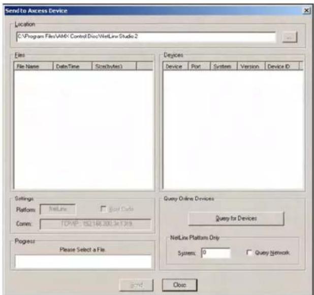
FIG. 4 Send to Axcess Dialog Window
- Browse to the location of the firmware file.
- Select the file within the Files frame.
-
Click Query for Devices.
-
The Query For Devices field will display a complete list of all devices currently connected to NetLinx Studio capable of accepting the firmware file selected. Select the Mio R-2.

In most cases, the Mio R-2 is the only device on the list.
- Click Send.
- After device firmware download, check one more time to verify the firmware version change.
- Click Close.
- Upon confirmation of a successful send, you can exit NetLinx Studio and disconnect the programming jack.
Persistent Serial Commands
There are a select number of persistent commands the Mio R-2 recognizes. Establish a HyperTerminal session with your device to use the following commands:
| Serial Commands | |
| @BRT Set Brightness level | Syntax:" 'BRIT-,,,''Variables:brightness level # = a value from 0 - 32.""@BRT-#" (Set LED Awake brightness level)"@BRT-#," (Set LED Awake brightness level, sleep brightness level)Example:(1) '' '@BRT-16'"Sets the awake brightness level to 50%. (2) '' '@BRT-32,5'"Sets the awake brightness level to 100% and sleep brightness level to approximately 15% |
| IRMODE # | Sets the IR transmission frequency to either 455KHz or 38KHzSyntax:"IRMODE #"Variables:# = 455 or 38Example:"IRMODE 455"Sets the IR transmission frequency to 455KHz. |
| SLEEP-# Force the device into | screen saver modeSyntax:" 'SLEEP-#' " (timed sleep; a persistent command)Variables:# = 0 - 60 in seconds; time to wait before going to sleep. Default is 30. 0 sets the device to never sleep.Example:SEND_COMMAND Panel, '' 'SLEEP-45'"Forces the device into screen saver mode after 45 seconds. |
Mio Remote Charging Base
The Mio remotes are complemented either with a Mio-RCC charging base (FG147-02) or the Mio-RCC rechargeable upgrade kit (FG147-03K). One charging base, a new back housing and a Mio-RBP rechargeable lithium ion battery (FG147-10) are included with the rechargeable upgrade kit. The charging base upgrade kit transforms the Mio R-1, R-2 and R-3 into a rechargeable device.
Begin with Installing The Rechargeable Battery for the Mio-RCC rechargeable upgrade kit (FG147-03K) or Charging The Mio Remote with Charging Base for the Mio-RCC charging base (FG147-02).
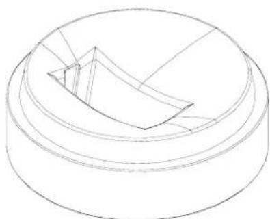
natural_image
Pure technical line drawing of a mechanical component with layered structure (no text or symbols)FIG. 5 Mio-RCC Charging Base
Specifications
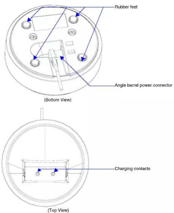
FIG. 6 Mio Remote Charging Base (Top and Bottom view)
The specifications for the Mio remote charging base and kit are as follows:
| Mio-RCC Remote Charging Kit (FG147-03K) with Base (FG147-02) Specifications | |
| Dimensions (HWD) Charging Base - 1.61 (4.09 cm) (height); 4.25 (10.80 cm) (diameter)Lithium Ion Battery - 2.13" x 1.38" x .28" (5.41 cm x 3.45 cm x .71 cm) | |
| Weight • 1.15 lbs (.52 kg) - Remote Charging Cradle• .15 lbs (.07 kg) - Power Supply• .06 lbs (.027 kg) - Rechargeable Lithium Battery | |
| Included Items: • Rechargeable Lithium Ion battery (4 hours battery life) Kit only• Back housing Kit only• Mio-RCC Charging base (FG147-02) with Power Supply• Power supply Kit only | |
| Other AMX Equipment: | • Mio-RCC Charging Base (FG147-02) with Power Supply• Mio R - 1 ( FG147)• Mio R-2 RF 418 (FG147-418)• Mio R-2 RF 433 (FG147-433)• Mio-RBP Rechargeable Lithium Ion Battery (FG147-10)• AXR-RF 418 MHZ RF Receiver (FG782-418)• AXR-RF 433 MHZ RF Receiver (FG782-433)• Mio Modero IR Receiver (FG5797-01xx; xx indicates color) |
Installing The Rechargeable Battery
- Flip and turn the Mio R-2 so that the buttons are facing away from you and the device is upside down.
- Holding the device in both hands, place your thumbs on the battery door and push up to slide the battery door free.
- If present, remove AAA batteries.
- Remove the 6 screws shown in FIG. 7.
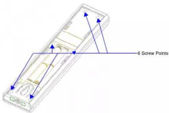
FIG. 7 6 Screw Points of The Back Housing
- Remove the back housing.
- Place the new housing on the device so that the rechargeable battery port connection is now accessible. See FIG. 8.
- Replace the 6 screws.
- Connect the terminal end of the Lithium Ion battery to the port shown in FIG. 8. It may be necessary to use a thin, blunt object to fully seat the battery connector within its port.
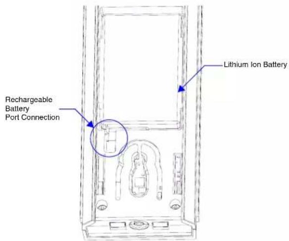
FIG. 8 Rechargeable Battery Port on The Mio Remote
- Press the battery between the rubber pads, with sticker showing, in the housing area of the Mio remote. Confirm battery is flush with bottom of battery enclosure on bottom housing.
- Replace the battery door and slide to lock it in place.
- Begin charging the battery.
Charging The Mio Remote with Charging Base
The Mio remotes receive power for charging from a charging base.
- Connect the terminal end of the power supply to the bottom external power port on the Mio remote charging base. See FIG. 6 for location.
-
Route the cable through the provided channel so that it comes out the side of the base.
-
Connect the power cord to an external power source.
-
Place the bottom of the Mio remote into the charging base so the contacts on the device are on top of the charging contacts inside the charging base. The Power LED on the Mio remote blinks red to indicate it is charging and illuminates solid red when it is done. Full charge cycle for a depleted battery is approximately 3 hours.
Avoid placing units equipped with AAA batteries in the charging base.
Changing Battery Modes
Configuration Mode
The configuration mode allows you to set the battery type. To enter configuration Mode:
- Press and hold the STOP button and the INPUT button simultaneously. The two buttons must be pressed within 0.1 seconds of each other and held down for 2 seconds. The device indicates you are now in configuration mode. See below for available modes.
Battery Type
- Pressing button "6" on the remote toggles the battery type between Normal and Recharge. The display indicates the selected type. The type of battery in the Mio R-1 dictates the battery type you need to set.
- Press the EXIT key when you are finished.
Your settings will not be lost in the event your batteries die or are removed.

Mio Remote Charging Base

It's Your World - Take Control™