Kon-Tiki E700 (2011) - Motorhome Swift - Free user manual and instructions
Find the device manual for free Kon-Tiki E700 (2011) Swift in PDF.

User questions about Kon-Tiki E700 (2011) Swift
0 question about this device. Answer the ones you know or ask your own.
Ask a new question about this device
Download the instructions for your Motorhome in PDF format for free! Find your manual Kon-Tiki E700 (2011) - Swift and take your electronic device back in hand. On this page are published all the documents necessary for the use of your device. Kon-Tiki E700 (2011) by Swift.
USER MANUAL Kon-Tiki E700 (2011) Swift
Swift Group, Dunswell Road, Cottingham, East Yorkshire | IU16 4JS.
Tel: 01482 875740 Fax: 01482 840082
email: enquiry@swiftgroup.co.uk
www.swiftgroup.co.uk
1091961
Issued February 2011
natural_image
Black-and-white landscape photo of a winding road leading toward a body of water with distant mountains under a clear sky (no text or symbols visible)Kon-Tiki / E700 Series
Specification, wiring diagrams and bulb chart


natural_image
Plain gray square with a white rounded border (no text or symbols)contents
Standard Specifications 2
Optional Specifications 3
Capacities 5
Towing Capabilities 6
Jacking 7
Wiring Diagrams 8
Bulb Replacement 15
Standard Specifications
| Model | Kon-Tiki 659 / E749 | Kon-Tiki 669 / E769 | Kon-Tiki 669 / E769 | Kon-Tiki 679 / E789 | Kon-Tiki 679 / E789 | Kon-Tiki 649 / E799 | Kon-Tiki 649 / E799 |
| Roof Profile Low Line Low Line High Line Low Line High Line Low Line High Line | |||||||
| Engine | Flat '160 MultiJet' diesel | Flat '160 MultiJet' diesel | Flat '160 MultiJet' diesel | Flat '160 MultiJet' diesel | Flat '160 MultiJet' diesel | Flat '160 MultiJet' diesel | Flat '160 MultiJet' diesel |
| Engine Capacity 2999cc 2999cc 2999cc 2999cc 2999cc 2999cc | |||||||
| Engine Power | 157bhp | 157bhp | 157bhp | 157bhp | 157bhp | 157bhp | 157bhp |
| Torque | 400Nm | 400Nm | 400Nm | 400Nm | 400Nm | 400Nm | 400Nm |
| Chassis | Flat AL-KD low line | Flat AL-KD low line | Flat AL-KD low line | Flat AL-KD low line | Flat AL-KD low line | Flat AL-KD low line | Flat AL-KD low line |
| Wheel base | 4.60m/15' 1"-0.80m/2' 7" | 4.60m/15' 1"-0.80m/2' 7" | 4.60m/15' 1"-0.80m/2' 7" | 4.60m/15' 1"-0.80m/2' 7" | 4.60m/15' 1"-0.80m/2' 7" | 4.80m/15' 1"-0.80m/2' 7" | 4.60m/15' 1"-0.80m/2' 7" |
| Designated Passenger Seats | 1 | 3 | 3 | 3 | 3 | 3 | 3 |
| Berths (sleeping positions) | 4 | 4 | 6 | 4 | 6 | 4 | 6 |
| Overall Length | 8.67m/ 28' 5" | 8.67m/ 28' 5" | 8.67m/ 28' 5" | 8.67m/ 28' 5" | 8.67m/ 28' 5" | 8.67m/ 28' 5" | 8.67m/ 28' 5" |
| Overall Width (mirrors folded) | 2.35m/ 7' 8" | 2.35m/ 7' 8" | 2.35m/ 7' 8" | 2.35m/ 7' 8" | 2.35m/ 7' 8" | 2.35m/ 7' 8" | 2.35m/ 7' 8" |
| Overall Height | 3.09m/ 10' 2" | 3.09m/ 10' 2" | 3.09m/ 10' 2" | 3.09m/ 10' 2" | 3.09m/ 10' 2" | 3.09m/ 10' 2" | 3.09m/ 10' 2" |
| Maximum Technical Permissible Laden Mass (A) | 5000kg | 5000kg | 5000kg | 5000kg | 5000kg | 5000kg | 5000kg |
| Mass in Running Order (3)† | 4085kg | 4228kg | 4288kg | 4293kg | 4353kg | 4320kg | 4380kg |
| Maximum User Payload (A-B) | 915kg | 772kg | 712kg | 707kg | 647kg | 680kg | 620kg |
| Unlodon Weight | 3766kg | 3909kg | 3969kg | 3974kg | 4034kg | 4001kg | 4061kg |
| Essential Habitation Equipment | 17kg | 17kg | 17kg | 17kg | 17kg | 17kg | 17kg |
| Thermal Insulation Grade | THREE | THREE | THREE | THREE | THREE | THREE | THREE |
| Bed Sizes | |||||||
| Front Double | 2.13m x 1.38m/ 7'0" x 4'6" | 2.13m x 1.38cm/ 7'0" x 4'6" | 2.13m x 1.38cm/ 7'0" x 4'6" | 2.13m x 1.38cm/ 7'0" x 4'6" | 2.13m x 1.38cm/ 7'0" x 4'6" | 2.13m x 1.38 cm/ 7'0" x 4'6" | 2.13m x 1.38cm/ 7'0" x 4'6" |
| Front Offside Single | 1.80m x 0.67m/ 5'11 x 2'2" | 1.80m x 0.67m/ 5'11 x 2'2" | 1.80m x 0.67m/ 5'11 x 2'2" | 1.80m x 0.67m/ 5'11 x 2'2" | 1.90m x 1.02m/ 6'3" x 3'4" | 1.90m x 1.02m/ 6'3" x 3'4" | |
| Rear Double | 1.89m x 1.35m/ 6'2" x 4'5" | 1.86m x 1.32m/ 6'1" x 4'4" | 1.86m x 1.32m/ 6'1" x 4'4" | 2.13m x 1.30m/ 7'0" x 4'3" | 2.13m x 1.30m/ 7'0" x 4'3" | 2.13m x 1.45m/ 7'0" x 4'7" | 2.13m x 1.45m/ 7'0" x 4'7" |
| Rear Offside Single | 1.88m x 0.73m/ 6'2" x 2'5" | 1.88m x 0.73m/ 6'2" x 2'5" | |||||
| Rear Neanside Single | 1.93m x 0.73m/ 6'4" x 2'5" | 1.93m x 0.73m/ 6'4" x 2'5" | |||||
| Overcab Bed | 1.91m x 1.37m/ 6'3" x 4'6" | 1.91m x 1.37m/ 6'3" x 4'6" | 1.91m x 1.37m/ 6'3" x 4'6" |
NOTE: 1. The Maximum User Payload includes: a) the conventional load (this is the allowance for passengers)
b) essential habitation equipment (items and fluids required for safe and proper functioning of habitation equipment)
c) optional equipment (items available from the manufacturer over and above the standard specification)
d) personal effects (those items not covered by the above)
2. The Mass in Running Order is the mass of the unladen vehicle including a 75kg allowance for the driver plus engine coolants and 90% of the fuel tank, water tank and gas capacity.
3. PLEASE TAKE CARE TO ENSURE THAT YOU HAVE ALLOWED FOR THE MASSES OF ALL ITEMS YOU INTEND TO CARRY IN THE MOTOR CARWAN,
e.g. passengers, optional equipment, essential habitation equipment and personal effects, such as clothing, food, pets, bicycles, sailboards, sports equipment etc.
4. WARNING - UNDER NO CIRCUMSTANCES SHOULD THE MAXIMUM TECHNICAL PERMISSIBLE LADEN MASS OF THIS MOTOR CARAVAN BE EXCEEDED.
* For optional roof ladder (add 200mm)
Optional Specifications
| Model Kon-Tiki 659 / E749 Kon-Tiki 669 / E769 Kon-Tiki 669 / E769 | |||
| Roof Profile Low Line Low Line High Line | |||
| Engine Flat '160 MultUet' diesel Auto Flat '160 MultUet' diesel Auto Flat '160 MultUet' diesel Auto | |||
| Engine Capacity 2993cc 2993cc 2993cc | |||
| Engine Power 157chp 157bhp 157chp | |||
| Torque 400Nm 400Nm 400Nm | |||
| Chassis Flat AL-KD low line Flat AL-KD low line Flat AL-KD low line | |||
| Wheel base | 4.60m/15' 1"- 0.80m/2' 7" | 4.60m/15' 1"- 0.80m/2' 7" | 4.60m/15' 1"- 0.80m/2' 7" |
| Designated Passenger Seats | 1 | 3 | 3 |
| Berths (sleeping positions) | 4 | 4 | 6 |
| Overall Length | 8.67m/ 28' 5" | 8.67m/ 28' 5" | 8.67m/ 28' 5" |
| Overall Width (mirrors folded) | 2.35m/ 7' 8" | 2.35m/ 7' 8" | 2.35m/ 7' 8" |
| Overall Height | 3.09m/ 10' 2" | 3.09m/ 10' 2" | 3.09m/ 10' 2" |
| Maximum Technical Penmissible Laden Mass (A) | 5000kg 5000kg 5000kg | ||
| Mass in Running Order (3)† | 4102kg 4245kg 4305kg | ||
| Maximum User Payload (A-B) | 898kg | 755kg | 695kg |
| Unlodon Weight | 3783kg 3926kg 3986kg | ||
| Essential Habitation Equipment | 17kg | 17kg | 17kg |
| Thermal Insulation Grade | THREE | THREE | THREE |
| Bed Sizes | |||
| Front Double | 2.13m x 1.38m/ 7'0" x 4'5" | 2.13m x 1.38cm/ 7'0" x 4'6" | 2.13m x 1.38cm/ 7'0" x 4'6" |
| Front Offside Single | 1.80m x 0.67m/ 5'11 x 2'2" | 1.80m x 0.67m/ 5'11 x 2'2" | |
| Rear Double | 1.89m x 1.35m/ 6'2" x 4'5" | 1.86m x 1.32m/ 6'1" x 4'4" | 1.86m x 1.32m/ 6'1" x 4'4" |
| Rear Offside Single | |||
| Rear Neanside Single | |||
| Overcab Bed | 1.91m x 1.37m/ 6'3" x 4'6" |
NOTE: 1. The Maximum User Payload includes: a) the conventional load (this is the allowance for passengers)
b) essential habitation equipment (items and fluids required for safe and proper functioning of habitation equipment)
c) optional equipment (items available from the manufacturer over and above the standard specification)
df personal effects (those items not covered by the above)
2. The Mass in Running Order is the mass of the unladen vehicle including a 75kg allowance for the driver plus engine coolants and 90% of the fuel tank, water tank and gas capacity.
3. PLEASE TAKE CARE TO ENSURE THAT YOU HAVE ALLOWED FOR THE MASSES OF ALL ITEMS YOU INTEND TO CARRY IN THE MOTOR CARWAN.
e.g. passengers, optional equipment, essential habitation equipment and personal effects, such as clothing, food, pets, bicycles, sailboards, sports equipment etc.
4. WARNING - UNDER NO CIRCUMSTANCES SHOULD THE MAXIMUM TECHNICAL PERMISSIBLE LADEN MASS OF THIS MOTOR CARAVAN BE EXCEEDED.
Optional Specifications
| Model Kon-Tiki 679 / E789 Kon-Tiki 679 / E789 Kon-Tiki 649 / E799 Kon-Tiki 649 / E799 | ||||
| Roof Profile Low Line High Line Low Line High Line | ||||
| Engine | Flat '160 MultiJet' diesel Auto | Flat '160 MultiJet' diesel Auto | Flat '160 MultiJet' diesel Auto | Flat '160 MultiJet' diesel Auto |
| Engine Capacity 2999cc 2999cc 2999cc 2999cc | ||||
| Engine Power 157chp 157bhp 157chp 157bhp | ||||
| Torque | 400Nm | 400Nm | 400Nm | 400Nm |
| Chassis | Flat AL KO low line | Flat AL KO low line | Flat AL KO low line | Flat AL KO low line |
| Wheel base | 4.60m/15' 1"-0.80m/2' 7" | 4.60m/15' 1"-0.80m/2' 7" | 4.60m/15' 1"-0.80m/2' 7" | 4.60m/15' 1"-0.80m/2' 7" |
| Designated Passenger Seats | 3 | 3 | 3 | 3 |
| Berths (sleeping positions) | 4 | 6 | 4 | 6 |
| Overall Length | 8.67m/ 28' 5" | 8.67m/ 28' 5" | 8.67m/ 28' 5" | 8.67m/ 28' 5" |
| Overall Width (mirrors folded) | 2.35m/ 7' 8" | 2.35m/ 7' 8" | 2.35m/ 7' 8" | 2.35m/ 7' 8" |
| Overall Height | 3.09m/ 10' 2" | 3.09m/ 10' 2" | 3.09m/ 10' 2" | 3.09m/ 10' 2" |
| Maximum Technical Permissible Laden Mass (A) | 5000kg | 5000kg | 5000kg | 5000kg |
| Mass in Running Order (3)† | 4310kg 4370kg 4337kg 4397kg | |||
| Maximum User Payload (A-B) | 690kg | 630kg | 663kg | 603kg |
| Unlodon Weight | 3991kg 4051kg 4018kg 4078kg | |||
| Essential Habitation Equipment | 17kg | 17kg | 17kg | 17kg |
| Thermal Insulation Grade | THREE | THREE | THREE | THREE |
| Bed Sizes | ||||
| Front Double | 2.13m x 1.38cm/ 7'0" x 4'6" | 2.13m x 1.38cm/ 7'0" x 4'6" | 2.13m x 1.38cm/ 7'0" x 4'6" | 2.13m x 1.38cm/ 7'0" x 4'6" |
| Front Offside Single | 1.80m x 0.67m/ 5'11 x 2'2" | 1.80m x 0.67m/ 5'11 x 2'2" | 1.90m x 1.02m/ 8'3" x 3'4" | 1.90m x 1.02m/ 6'3" x 3'4" |
| Rear Double | 2.13m x 1.30m/ 7'0" x 4'3" | 2.13m x 1.30m/ 7'0" x 4'3" | 2.13m x 1.40m/ 7'0" x 4'7" | 2.13m x 1.40m/ 7'0" x 4'7" |
| Rear Offside Single | 1.88m x 0.73m/ 6'2" x 2'5" | 1.88m x 0.73m/ 6'2" x 2'5" | ||
| Rear Neanside Single | 1.93m x 0.73m/ 8'4" x 2'5" | 1.93m x 0.73m/ 6'4" x 2'5" | ||
| Overcab Bed | 1.91m x 1.37m/ 6'3" x 4'6" | 1.91m x 1.37m/ 6'3" x 4'6" | ||
NOTE: 1. The Maximum User Payload Includes: a) the conventional load (this is the allowance for passengers)
b) essential habitation equipment (items and fluids required for safe and proper functioning of habitation equipment)
c) optional equipment (items available from the manufacturer over and above the standard specification)
d) personal effects (those items not covered by the above)
2. The Mass in Running Order is the mass of the unladen vehicle including a 75kg allowance for the driver plus engine coolants and 90% of the fuel tank, water tank and gas capacity.
3. PLEASE TAKE CARE TO ENSURE THAT YOU HAVE ALLOWED FOR THE MASSES OF ALL ITEMS YOU INTEND TO CARRY IN THE MOTOR CARWAN,
e.g. passengers, optional equipment, essential habitation equipment and personal effects, such as clothing, food, pets, bicycles, sailboards, sports equipment etc.
4. WARNING - UNDER NO CIRCUMSTANCES SHOULD THE MAXIMUM TECHNICAL PERMISSIBLE LADEN MASS OF THIS MOTOR CARAVAN BE EXCEEDED.
Capacities
Water Tank Capacities
| Fresh Water Tank | Waste Water Tank | Water Heater | Toilet Tank (Flushing) | |
| Kon-Tiki / E700 Series 125 litre 100 litre 12 litre 7 litre |
Gas Capacities
| Capacity | |
| Kon-Tiki / E700 Series | 2 x 13kg |
The above are recommended gas bottle sizes
NOTICE
For technical data on the base vehicle please refer to manufacturer's handbook
Towing Capabilities
Swift Kon-Tiki / E700 Series Towing Capabilities
The maximum trailer weight is limited by the Gross Train Weight which must not be exceeded. For example, if the vehicle is at the maximum MTPLM of 5000kg, then the maximum trailer weight possible is 1000kg. Reducing the weight of the vehicle by removing payload, will allow you to increase the trailer weight up to a maximum of 1600kg.
To ensure adequate road holding, the load on the front axle, under all conditions, must not be less than 40% or more than 70% of the total weight.
Care must be taken when distributing loads. The loadings and weights above are maximums and must not be exceeded under any circumstances.
CAUTION: When fitting a towbar, it must meet certain minimum requirements as specified by Type Approval Regulations. The bar will have marked on it the approval standard (94/20/EC) and the maximum download, or noseweight, that it can accept. It must fit the manufacturer's approved mounting points and must not obscure the towing vehicle's number plate.
sWIFt Kon-tIKI / e700 seRles
natural_image
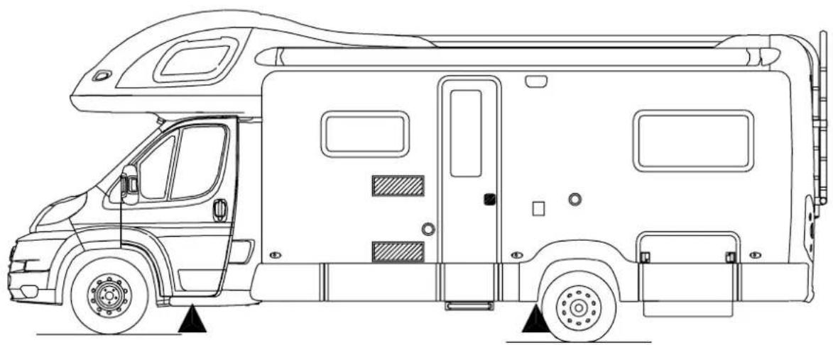
Line drawing of a two-wheeled vehicle with front and side views, no text or symbols presentJacking Points for High-Line and Low-Line: ▲
Wiring Diagrams
RoAd IIGHtInG
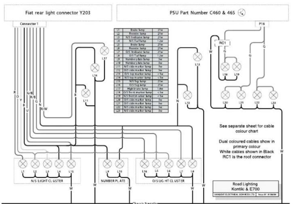
Copyright Sargent Electrical Services Ltd, 1998 all rights reserved. Subject to change without prior notice,
Wiring Diagrams
consUmeR cIRcUlts - RooF
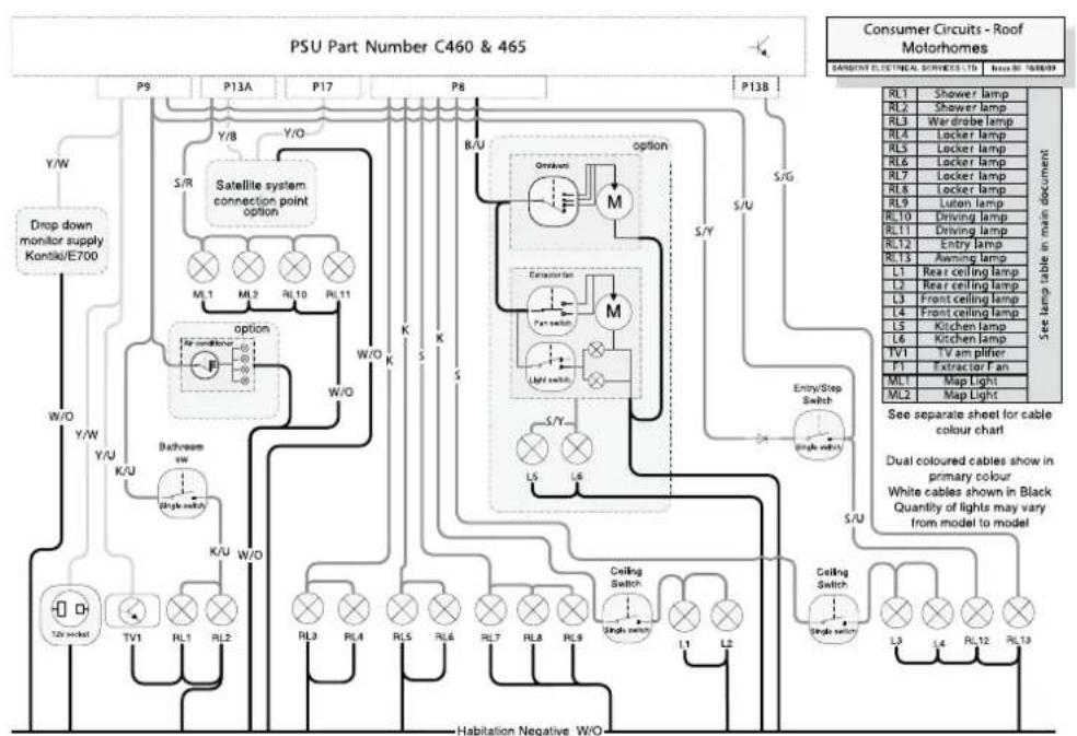
flowchart
graph TD
    A["PSU Part Number C460 & 465"] --> B["P9"]
    A --> C["P13A"]
    A --> D["P17"]
    A --> E["P8"]
    A --> F["P13B"]
    B --> G["Y/W"]
    C --> H["Y/B"]
    D --> I["Y/O"]
    E --> J["R/U"]
    F --> K["S/G"]
    G --> L["Drop down monitor supply\nKontiko/E700"]
    H --> M["S/R"]
    I --> N["S/R"]
    J --> O["Satellite system connection point option"]
    K --> P["Option"]
    L --> Q["Induction"]
    M --> R["Operation"]
    N --> S["Light switch"]
    O --> T["Entry/Step Switch"]
    P --> U["Drain lamp"]
    Q --> V["Entry lamp"]
    R --> W["Drain lamp"]
    S --> X["Drain lamp"]
    T --> Y["Drain lamp"]
    U --> Z["Drain lamp"]
    V --> AA["Drain lamp"]
    W --> AB["Drain lamp"]
    X --> AC["Drain lamp"]
    Y --> AD["Drain lamp"]
    Z --> AE["Drain lamp"]
    AA --> AF["Drain lamp"]
    AB --> AG["Drain lamp"]
    AC --> AH["Drain lamp"]
    AD --> AI["Drain lamp"]
    AE --> AJ["Drain lamp"]
    AF --> AK["Drain lamp"]
    AG --> AL["Drain lamp"]
    AH --> AM["Drain lamp"]
    AI --> AN["Drain lamp"]
    AJ --> AO["Drain lamp"]
    AK --> AP["Drain lamp"]
    AL --> AQ["Drain lamp"]
    AM --> AR["Drain lamp"]
    AN --> AS["Drain lamp"]
    AO --> AT["Drain lamp"]
    AP --> AU["Drain lamp"]
    AQ --> AV["Drain lamp"]
    AR --> AW["Drain lamp"]
    AS --> AX["Drain lamp"]
    AT --> AY["Drain lamp"]
    AU --> AZ["Drain lamp"]
    AV --> BA["Drain lamp"]
    AW --> BB["Dual coloured cables show in primary colour\nWhite cables shown in Black\nQuantity of lights may vary from model to model"]
    AX --> BC["Habitation Negative W/O"]
    AY --> BD["T2N socket"]
    AY --> BE["TV1"]
    AY --> BF["RL1"]
    AY --> BG["RL2"]
    AY --> BH["K/U"]
    AY --> BI["W/O"]
    B --> BJ["M1.1 ML2 RL10 RL11"]
    B --> BK["K/U W/O K/S"]
    B --> BL["M1.2 ML2 RL10 RL11"]
    B --> BM["K/U W/O K/S"]
    B --> BN["M1.3 ML2 RL10 RL11"]
    B --> BO["K/U W/O K/S"]
    B --> BP["M1.4 ML2 RL10 RL11"]
    B --> BQ["K/U W/O K/S"]
    BQ --> BR["M1.5 ML2 RL10 RL11"]
    BQ --> BS["K/U W/O K/S"]
    BQ --> BT["M1.6 ML2 RL10 RL11"]
    BQ --> BU["K/U W/O K/S"]
    BQ --> BV["M1.7 ML2 RL10 RL11"]
    BQ --> BW["K/U W/O K/S"]
    BQ --> BX["M1.8 ML2 RL10 RL11"]
    BQ --> BY["K/U W/O K/S"]
    BQ --> BZ["M1.9 ML2 RL10 RL11"]
Copyright: Sappett Electrical Services Ltd, 2008 and rights reserved. Subject to changes without prior notice.
Wiring Diagrams
poWeR cIRcUlts
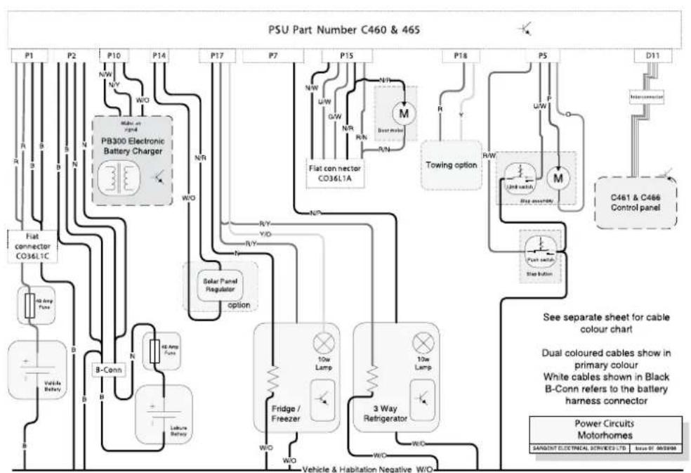
Copyright: Sargent Electrical Between Ltd., 2009 all rights reserved. Subject to charge without prior notice.
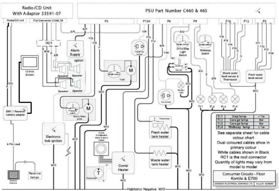
Wiring Diagrams
consUmeR cIRcUlts - FlooR
flowchart
graph TD
    A["Radio/CD Unit With Adaptor 33591-07"] --> B["RSU Part Number C460 & 465"]
    B --> C["RSU Part Number C460 & 465"]
    C --> D["RSU Part Number C460 & 465"]
    D --> E["RSU Part Number C460 & 465"]
    E --> F["RSU Part Number C460 & 465"]
    F --> G["RSU Part Number C460 & 465"]
    G --> H["RSU Part Number C460 & 465"]
    H --> I["RSU Part Number C460 & 465"]
    I --> J["RSU Part Number C460 & 465"]
    J --> K["RSU Part Number C460 & 465"]
    K --> L["RSU Part Number C460 & 465"]
    L --> M["RSU Part Number C460 & 465"]
    M --> N["RSU Part Number C460 & 465"]
    N --> O["RSU Part Number C460 & 465"]
    O --> P["RSU Part Number C460 & 465"]
    P --> Q["RSU Part Number C460 & 465"]
    Q --> R["RSU Part Number C460 & 465"]
    R --> S["RSU Part Number C460 & 465"]
    S --> T["RSU Part Number C460 & 465"]
    T --> U["RSU Part Number C460 & 465"]
    U --> V["RSU Part Number C460 & 465"]
    V --> W["RSU Part Number C460 & 465"]
    W --> X["RSU Part Number C460 & 465"]
    X --> Y["RSU Part Number C460 & 465"]
    Y --> Z["RSU Part Number C460 & 465"]
    Z --> AA["RSU Part Number C460 & 465"]
    AA --> AB["RSU Part Number C460 & 465"]
    AB --> AC["RSU Part Number C460 & 465"]
    AC --> AD["RSU Part Number C460 & 465"]
    AD --> AE["RSU Part Number C460 & 465"]
    AE --> AF["RSU Part Number C460 & 465"]
    AF --> AG["RSU Part Number C460 & 465"]
    AG --> AH["RSU Part Number C460 & 465"]
    AH --> AI["RSU Part Number C460 & 465"]
    AI --> AJ["RSU Part Number C460 & 465"]
    AJ --> AK["RSU Part Number C460 & 465"]
    AK --> AL["RSU Part Number C460 & 465"]
    AL --> AM["RSU Part Number C460 & 465"]
    AM --> AN["RSU Part Number C460 & 465"]
    AN --> AO["RSU Part Number C460 & 465"]
    AO --> AP["RSU Part Number C460 & 465"]
    AP --> AQ["RSU Part Number C460 & 465"]
    AQ --> AR["RSU Part Number C460 & 465"]
    AR --> AS["RSU Part Number C460 & 465"]
    AS --> AT["RSU Part Number C460 & 465"]
    AT --> AU["RSU Part Number C460 & 465"]
    AU --> AV["RSU Part Number C460 & 465"]
    AV --> AW["RSU Part Number C460 & 465"]
    AW --> AX["RSU Part Number C460 & 465"]
    AX --> AY["RSU Part Number C460 & 465"]
    AY --> AZ["RSU Part Number C460 & 465"]
    AZ --> BA["RSU Part Number C460 & 465"]
    BA --> BB["RSU Part Number C460 & 465"]
    BB --> BC["RSU Part Number C460 & 465"]
    BC --> BD["RSU Part Number C460 & 465"]
    BD --> BE["RSU Part Number C460 & 465"]
    BE --> BF["RSU Part Number C460 & 465"]
    BF --> BG["RSU Part Number C460 & 465"]
    BG --> BH["RSU Part Number C460 & 465"]
    BH --> BI["RSU Part Number C460 & 465"]
    BI --> BJ["RSU Part Number C460 & 465"]
    BJ --> BK["RSU Part Number C460 & 465"]
    BK --> BL["RSU Part Number C460 & 465"]
    BL --> BM["RSU Part Number C460 & 465"]
    BM --> BN["RSU Part Number C460 & 465"]
    BN --> BO["RSU Part Number C460 & 465"]
    BO --> BP["RSU Part Number C460 & 465"]
    BP --> BQ["RSU Part Number C460 & 465"]
    BQ --> BR["RSU Part Number C460 & 465"]
    BR --> BS["RSU Part Number C460 & 465"]
    BS --> BT["RSU Part Number C460 & 465"]
    BT --> BU["RSU Part Number C460 & 465"]
    BU --> BV["RSU Part Number C460 & 465"]
    BV --> BW["RSU Part Number C460 & 465"]
    BW --> BX["RSU Part Number C460 & 465"]
    BX --> BY["RSU Part Number C460 & 465"]
    BY --> BZ["RSU Part Number C460 & 465"]
    BZ --> CA["RSU Part Number C460 & 465"]
    CA --> CB["RSU Part Number C460 & 465"]
    CB --> CC["RSU Part Number C460 & 465"]
    CC --> CD["RSU Part Number C460 & 465"]
    AD --> CE["PSU Part Number C398L1B"]
    AE --> CF["PSU Part Number C398L1B"]
    AF --> CG["PSU Part Number C398L1B"]
    AG --> CH["PSU Part Number C398L1B"]
    AH --> CI["PSU Part Number C398L1B"]
    AI --> CJ["PSU Part Number C398L1B"]
    AJ --> CK["PSU Part Number C398L1B"]
    AK --> CL["PSU Part Number C398L1B"]
    AL --> CM["PSU Part Number C398L1B"]
    AM --> CN["PSU Part Number C398L1B"]
    AO --> CO["PSU Part Number C398L1B"]
    CP --> CP1["Pump Control System with Sensor and Cable"]
Copyright Sargent Electrical Services Ltd, 2008 all rights reserved. Subject to charge without prior notice.
Wiring Diagrams
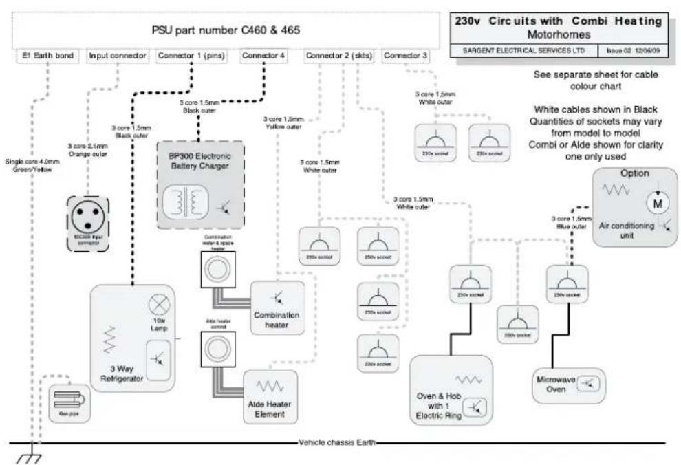
230v cIRcUlts
flowchart
graph TD
    A["PSU part number C460 & 465"] --> B["E1 Earth bond"]
    A --> C["Input connector"]
    A --> D["Connector 1 (pins)"]
    A --> E["Connector 4"]
    A --> F["Connector 2 (skts)"]
    A --> G["Connector 3"]
    B --> H["BC300 Input connector"]
    C --> I["BP300 Electronic Battery Charger"]
    D --> I
    E --> I
    F --> I
    G --> I
    H --> J["3 Way Refrigerator"]
    I --> K["Combination heater & space heater"]
    I --> L["Aide Heater Element"]
    J --> M["10w Lamp"]
    K --> N["Aide Heater Control"]
    L --> O["Aide Heater Control"]
    M --> P["Aided Heater Element"]
    N --> Q["Aided Heater Control"]
    P --> R["Aided Heater Control"]
    Q --> S["Aided Heater Control"]
    R --> T["Aided Heater Control"]
    S --> U["Aided Heater Control"]
    T --> V["Aided Heater Control"]
    U --> W["Aided Heater Control"]
    V --> X["Aided Heater Control"]
    W --> Y["Aided Heater Control"]
    X --> Z["Aided Heater Control"]
    Y --> AA["Aided Heater Control"]
    Z --> AB["Aided Heater Control"]
    AA --> AC["Aided Heater Control"]
    AB --> AD["Aided Heater Control"]
    AC --> AE["Aided Heater Control"]
    AD --> AF["Aided Heater Control"]
    AE --> AG["Aided Heater Control"]
    AF --> AH["Aided Heater Control"]
Copyright: Sargent Electrical Services Ltd, 2008 all rights reserved. Subject to change without prior notice.
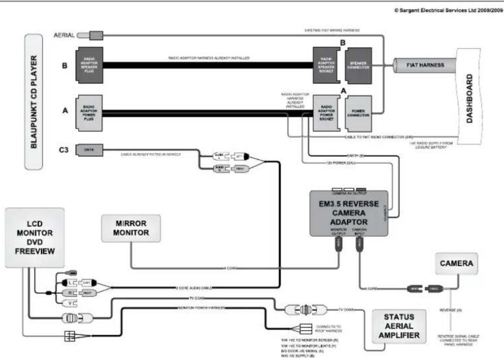
Wiring Diagrams
Av eqUIpment
flowchart
graph TD
    A["BLAUPUNKT CD PLAYER"] --> B["AERIAL"]
    B --> C["B"]
    C --> D["A"]
    D --> E["C3"]
    E --> F["LCD MONITOR DVD FREEVIEW"]
    F --> G["MIRROR MONITOR"]
    G --> H["EM3.5 REVERSE CAMERA ADAPTOR"]
    H --> I["CAMERA"]
    I --> J["STATUS AERIAL AMPLIFIER"]
    J --> K["REVERSE (R)"]
    K --> L["CAMERA"]
    L --> M["REVERSE SIGNAL CABLE CONNECTED TO REAR PANEL HORNES"]
    H --> N["CONNECT TO ROOT HORNES"]
    H --> O["TV DOWN"]
    H --> P["TV DOWN"]
    H --> Q["2000+ MODE AUDIO CABLE"]
    H --> R["MONITOR POWER HORNES"]
    H --> S["CONNECT TO ROOT HORNES"]
    H --> T["TV DOWN"]
    H --> U["YTW -VS TO MONITOR SCREEN (R)"]
    H --> V["YTW -VS TO MONITOR LIGHTS (R)"]
    H --> W["NO DOOR, VS SIGNAL (R)"]
    H --> X["NO -VS SUPPLY (R)"]
    H --> Y["COMPS 10000"]
    H --> Z["COMPS 10000"]
    H --> AA["COMPS 10000"]
    H --> AB["CABLE ALREADY FITTED IN MODELS"]
    AB --> AC["CABLE ALREADY FITTED IN MODELS"]
    AC --> AD["AIRIOR POWER PLUG"]
    AD --> AE["AIRIOR ADAPTOR SPEAKER PLUG"]
    AE --> AF["RADIO ADAPTOR HORNES ALREADY INSTALLED"]
    AF --> AG["RADIO ADAPTOR STEAKER SOCKET"]
    AG --> AH["FIAT HARNESS"]
    AH --> AI["DASHBOARD"]
    AI --> AJ["EXISTING FAT WRIND HARNESS"]
Wiring Diagrams
cAble coloUR cHART
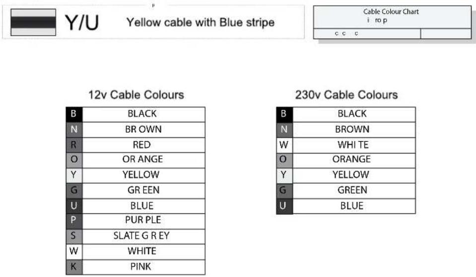
Y/U
Yellow cable with Blue stripe
| Cable Colour Charti ro p | |
| c c c | |
12v Cable Colours
| B | BLACK |
| N | BR OWN |
| R | RED |
| O | OR ANGE |
| Y | YELLOW |
| G | GREEN |
| U | BLUE |
| P | PUR PLE |
| S | SLATE G REY |
| W | WHITE |
| K | PINK |
230v Cable Colours
| B | BLACK |
| N | BROWN |
| W | WHI TE |
| O | ORANGE |
| Y | YELLOW |
| G | GREEN |
| U | BLUE |
Capey y n 11 12 13 14 15
Bulb Replacement
| Road Lights | ||
| Application Bulb Reference Bulb Rating | ||
| Front marker light LED complete lamp 12v <1w | ||
| Side marker light W5W 12v 5w | ||
| Rear high level marker light LED complete lamp 12v <1w | ||
| High level stop lamp T5/13.5 12v 2.3w | ||
| Rear indicator lamp PY21 Orange 12v 21w | ||
| Rear Tail lamp LED complete lamp 12v 1.2w | ||
| Rear Stop lamp P21 12v 21w | ||
| Rear reverse lamp P21 12v 21w | ||
| Rear fog lamp | P21 12v 21w | |
| Number plate light | C5W | 12v 5w |
| Interior / Other | ||
| Downlighters Halogen capsule bulb G4 12v 10w | ||
| Downlighters, LED, main habitation (dry) areas | FEM0470 complete lamp | 12v LE |
| Downlighters, LED, shower (wet) areas | FEM0441 complete lamp | 12v LED |
| Locker spotlights, LED | FEM0440 complete lamp | 12v LED |
| Cooker hood mounted lamps | GU4/MR11 Dichroic bulb | GU4 12v 10w |
| Panel mounted fluorescent lamps | 300mm Fluorescent bulb 12v 8w | |
| Panel mounted fluorescent lamps | 600mm Fluorescent bulb | 12v 13w |
| Furniture mounted cold cathode fluorescent lamps | 530mm complete lamp, front fixed | 12v 5w CCFL |
| Underfloor mounted cold cathode fluorescent lamps | 530mm complete lamp, rear fixed | 12v 5w CCFL |
| Garage strip lamps | 500mm LED complete unit | 12v 2.2w LED |
| Garage round lamps | 21 LED complete unit | 12v LED |
| Skylight surround fluorescent lamps | 300mm Fluorescent bulb 12v 8w | |
| Luton Fluorescent lamps | 300mm Fluorescent bulb 12v 8w | |
| B-pillar map reading lamps | GU4/MR11 Dichroic bulb | GU4 12v 10w |
| Low level walkway lamps | Small diameter LED complete lamp | 12v 3w LED |
| Entrance step lamp | LED complete lamp | 12v LED |
| Wardrobe lamp Halogen capsule bulb GU4 12v 5w | ||
| Awning lamp, LED | 500mm LED complete unit | 12v 2.2w LED |
Note: Not all lights feature on all models within a range
Replacement instructions
Kon tIKI / e700 seRles RoAd IIGHt bUIb Access
ReAR IIGHT cIUsteR:
To access the tail lamp, indicator lamp or low level brake lamps, the silver trim panel must first be removed. The trim panel is secured with a combination of plastic Velcro and stud fixings. To remove, apply pressure to the top corner and pull. Working downwards, release all the fixings
Below the trim panel is a black light carrier panel, housing the lamps. Release the three screws located close to the corners of each carrier, and then this too can be pulled directly away from the rear of the vehicle.
To replace the light carrier align the screw holes and replace fixing screws at each corner of carrier.
Align the silver trim piece and push firmly against rear of vehicle to ensure the plastic Velcro is fully engaged.
IndlcAtoR |Amps - ReplAcInG
Bulb access is from rear of lamp.
Remove the trim panel and light carrier as described previously.
At the rear of the lamp, twist the bulb holder relative to the lamp body to release, and withdraw the bulb holder and bulb.
Bulbs are a bayonet fitting – apply slight pressure on bulb towards light fitting, and twist to release.
Re-position the bulb holder into the lamp and twist to lock in place.
Replace the light carrier and trim piece as described above.
ReveRse |Amps - ReplAcInG
Bulb access is from rear of lamp.
Remove the trim panel and light carrier as described previously.
At the rear of the lamp, twist the bulb holder relative to the lamp body to release, and withdraw the bulb holder and bulb.
Bulbs are a bayonet fitting – apply slight pressure on bulb towards light fitting, and twist to release.
Re-position the bulb holder into the lamp and twist to lock in place.
Replace the light carrier and trim piece as described above.
tAll Iamps - ReplAclnG
The tail lamp is a LED cluster and has no user serviceable parts inside.
Only replacement of the whole lamp is possible – first remove the Silver trim piece and light carrier as described previously.
Unplug the lamp from the harness, by squeezing the small tab on the side of the connector, and pulling the two halves away from each other.
Remove the reverse lamp as described above.
Remove the three screws securing tail lamp LED ring to the black carrier
Replace lamp ensuring correct screws are used to secure and reverse procedure to re-fit lamp, reverse lamp, light carrier and trim piece.
IoW level stop Iamps
Bulb access is from rear of lamp.
Remove the trim panel and light carrier as described above.
At the rear of the lamp, twist the bulb holder relative to the lamp body to release, and withdraw the bulb holder and bulb.
Bulbs are a bayonet fitting – apply slight pressure on bulb towards light fitting, and twist to release.
Re-position the bulb holder into the lamp and twist to lock in place
Replace the light carrier and trim piece as described above.
ReAR FoG IIGHts
Bulb access is from rear of lamp.
The light fitting can be accessed from underneath the rear of the vehicle.
At the rear of the lamp, twist the bulb holder relative to the lamp body to release, and withdraw the bulb holder and bulb.
Please note: The visible rubber terminal cover is not fixed to the bulb holder, and it may be easier to grip the bulb holder with this removed.
Bulbs are a bayonet fitting – apply slight pressure on bulb towards light fitting, and twist to release.
Re-position the bulb holder into the lamp and twist to lock in place.
FRont oR ReAR HIGH level mARKeR / position Iamps (Red / cleAR lense)
These lamps are LED and have no user serviceable parts inside.
Replacements should be undertaken by your dealer, as the lamps are sealed onto the mounting panel.
HIGH level bRAKe Iamp
This lamp is single piece and has no user serviceable parts inside.
Remove the screw at both ends of lamp, and withdraw whole fitting away from rear panel of motorhome.
Please note: The screws which retain the lamp also retain the reverse camera housing.
Unplug the lamp from the harness, by squeezing the small tab on the side of the connector, and pulling the connector away from the lamp.
Re-connect the new lamp to harness, and secure with the original two screws.
Lamp retaining screws are fixed into a rubber sleeve with a threaded insert, often known as a rawlnut. If lamp has been removed and re-fitted several times the rubber sleeve may need replacing, these are available through your dealer.
nUmbeR plAte lAmps
Bulb access is from via the front lense of each lamp
Remove the two screws in the lens of the lamp, and remove
Lever the bulb out of retaining clips
Reverse the procedure to re-fit a new bulb and the light lens
Replacement instructions
slide mARKeR / position Iamps
Bulb access is from rear of lamp
If rear of lamp is visible from inside the vehicle:
Depending on the location, a small brown plastic cover may be present covering the connections to the lamp. Remove the screws in the cover to release and access the rear of the lamp.
The harness plugs directly into the bulb holder – twist the bulb holder relative to the lamp body to release, and withdraw the bulb holder and bulb.
Bulbs are push fit into bulb holder – pull bulb directly away from holder to release
Reverse the procedure to replace the bulb in the holder, holder in the lamp and the lamp onto the motorhome body. Replace plastic cover.
If rear of lamp is not visible from inside the vehicle:
Remove the 2 screws from the front of the light fitting, and withdraw the whole fitting from motorhome body.
The harness plugs directly into the bulb holder – twist the bulb holder relative to the lamp body to release, and withdraw the bulb holder and bulb.
Bulbs are push fit into bulb holder – pull bulb directly away from holder to release.
Reverse the procedure to replace the bulb in the holder, holder in the lamp and the lamp onto the motorhome body.