RPM1521E - Uncategorized Minuteman - Free user manual and instructions
Find the device manual for free RPM1521E Minuteman in PDF.

User questions about RPM1521E Minuteman
0 question about this device. Answer the ones you know or ask your own.
Ask a new question about this device
Download the instructions for your Uncategorized in PDF format for free! Find your manual RPM1521E - Minuteman and take your electronic device back in hand. On this page are published all the documents necessary for the use of your device. RPM1521E by Minuteman.
USER MANUAL RPM1521E Minuteman
by Para Systems, Inc.
Remote Power Manager RPM1521E
User's Manual
natural_image
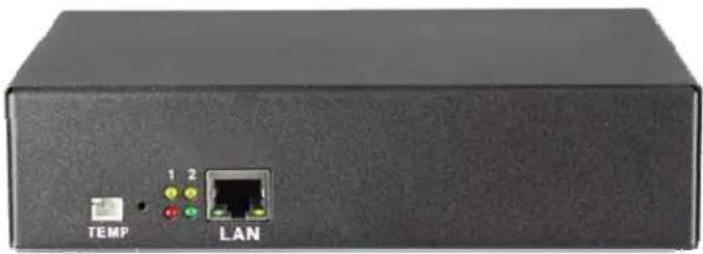
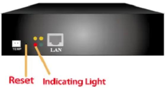
Front view of a black electronic device with labeled ports (TEMP and LAN) and colored indicators (1, 2)Table of Contents
1. Product Introduction ......4
1-1 Applications ....4
1-2 Product Features....5
1-3 Control and Indicators 6
1-4 Specifications ....7
1-5 Package Contents 8
1-6 Receiving Inspection 8
2. Installation and Setup....9
2-1 Hardware Installation 9
2-2 Setup Procedure 11
3. Web Operation ....16
3-1 System Login....16
3-2 Monitor Tab....17
3-2-1 Power Switch Operation....18
3-2-2 Power 19
3-2-3 Safety Shutdown 19
3-2-4 Schedule 20
3-2-5 Auto-Ping....20
3-2-6 Peripheral....21
3-2-7 Copy 22
3-2-8 Temperature 22
3-3 System Tab....23
3-3-1 Network....23
3-3-2 Mail Server....24
3-3-3 SMS Server 25
3-3-4 SNMP 26
3-3-5 Syslog 27
3-3-6 Peripheral 27
3-3-7 Other....28
3-4 Firewall Tab....29
3-4-1 IP Filter....29
3-4-2 MAC Filter 30
3-5 Account Tab....31
3-6 TimeSync Tab....34
3-7 Chart 35
3-8 Event Tab 36
3-9 Upgrade Tab....37
Appendix 39
A1 Shutdown Agent Installation....39
A2 Reset to Default 45
A3 Obtaining Technical Support 46
A4 Limited Product Warranty 47
© COPYRIGHT 2015 BY PARA SYSTEMS, INC.
All Rights Reserved. All rights of this User Manual (“Manual”), including but not limited to the content, information, and figures are solely owned and reserved by Para Systems, Inc. (“Para Systems”). The Manual can only be applied to the operation or the use of this product. Any disposition, duplication, dissemination, reproduction, modification, translation, extraction, or usage of this Manual in whole or in part is prohibited without the prior written permission of Para Systems. Given that Para Systems will continuously improve and develop the product, changes may be made to the information in this Manual at any time without obligation to notify any person of such revision or changes. Para Systems will make all possible efforts to secure the accuracy and the integrity of this Manual. Para Systems disclaims any kinds or forms of warranty, guarantee, or undertaking, either expressly or implicitly, including but not limited to the completeness, faultlessness, accuracy, non-infringement, merchantability or fitness for a particular purpose of the Manual.
An Important Notice
This manual contains important safety instructions that should be followed during the installation and the operation of the Remote Power Manager (RPM).
SAVE THESE INSTRUCTIONS
• To ensure safety in all applications ensure that a Qualified Service Personnel installs the system.
- Make sure that the AC Utility outlet is properly grounded.
- Do not open the unit there are no user serviceable parts inside. Servicing of RPM should be performed by Qualified Service Personnel Only.
- Please make sure that the input voltage of the RPM matches the supply voltage.
- Make sure the RPM is installed in the proper environment as specified.
- This RPM series is ONLY intended to be installed in an indoor temperature controlled environment that is free of conductive contaminants.
- Do not operate the RPM in: extremely dusty and/or unclean areas, locations near heating devices, water or excessive humidity, or where the RPM is exposed to direct sunlight.
- Select a location, which will provide good air circulation for the RPM at all times.
- CAUTION – To reduce the risk of fire, connect only to a branch circuit with over current protection in accordance with the National Electric Code.
- CAUTION - Connect the RPM to a two pole, three wire grounding AC wall outlet. The receptacle must be connected to the appropriate branch protection (circuit breaker or fuse). Connection to any other type of receptacle may result in a shock hazard and violate local electrical codes. Do not use extension cords, adapter plugs, or surge strips.
- Route power cords so they cannot be walked on or damaged.
- CAUTION - To reduce the risk of electrical shock with the installation of this RPM equipment and the connected equipment, the user must ensure that the combined sum of the AC leakage current does not exceed 3.5mA.
- CAUTION - To de-energize the outputs of the RPM: Disconnect the RPM from the AC wall outlet.
Para Systems Life Support Policy
As a general policy, Para Systems Inc. (Para Systems) does not recommend the use of any of its products in life support applications where failure or malfunction of the Para Systems product can be reasonably expected to cause failure of the life support device or to significantly affect its safety or effectiveness. Para Systems does not recommend the use of any of its products in direct patient care. Para Systems will not knowingly sell its products for use in such applications unless it receives in writing assurances satisfactory to Para Systems that (a) the risks of injury or damage have been minimized, (b) the customer assumes all such risks, and (c) the liability of Para Systems Inc. is adequately protected under the circumstances.
1. Product Introduction
The RPM1521E is an Internet ready SNMP device designed with integrated versatile functions including power control, temperature monitoring, and remote web administration, event alerts, which helps system administrators or IT personnel to monitor and control their connected equipment and take preventive measures when needed. Allows an administrator to remotely control the AC power for two connected devices, such as: servers, routers, modems, DVRs, security and telephone equipment.
The RPM1521E offers easy setup, user-friendly communications and control methods. Easily connects to the LAN using normal Ethernet connection. Once connected and properly set up, the administrator can manage the AC power of the devices from anywhere in the world via a web browser, which greatly reduces the need for on-site service.
Additional benefits of the RPM1521E:
- Improves administrative efficiencies with remote power monitoring and control
- Reduces system down time without dispatching service personnel to remote locations
• Monitoring and management from anywhere in the world - Surge protection for the connected equipment
• Temperature monitoring
• Supports secure email (TLS) such as Gmail - Notification via email, SNMP trap, SMS text messaging
1-1 Applications
• Monitoring and management of computer equipment rooms.
• Intelligent power management of data center and networking equipment.
- Power scheduling of machinery equipment for the factory building.
- Power control and monitoring for home appliances.
- Other power equipment management, scheduling and monitoring.
1-2 Product Features
- IP-addressable Remote Power Manager with built-in web server and 2 power outlets.
- Control power equipment remotely via the Internet without the presence of service personnel.
- The power switch is used to completely power down the RPM1521E.
- Each AC power outlet can be independently switched ON/OFF, power cycled for immediate reboots or rebooted with timed delays, power cycle sequencing with assigned priority and power event scheduling.
• LEDs for power status and control mode indication. - Supports Power Start sequencing to prevent all of the connected devices from starting simultaneously to limit the in-rush current to the RPM.
- Easy web setup for scheduling daily, weekly, monthly and yearly power operations on a specific outlet.
- The Auto-Ping feature will monitor and auto detect any failed network equipment and perform a timed reboot.
- IP filter/mask function helps manage user privileges and prevent unauthorized access to the control menu through the network.
- Instant email, SMS text messages and SNMP trap notification will be generated when power events occurred.
- Provides multi-group accounts (administrator/manager/general) to let different users control different power outlets.
• Supports SYSLOG.
• Supports Web API function. - Supports SSL.
• Overload and connected equipment protection via the input circuit breaker. - Rack mountable design with holes on the side of the metal enclosure for an optional rack-mounting kit.
- Provides Surge protection to eliminate disrupting and damaging effects of momentary voltage spikes or impulses from other power transients.
- Optional temperature probe.
• Supports downloading and uploading configuration files
1-3 Control and Indicators


| 1 | LED #1 is illuminated when output receptacle #1 is ON.LED #2 is illuminated when output receptacle #2 is ON. |
| 2 | Reset LED will flash when the Reset function is being performed. |
| 3 | Utility Power LED is illuminated when there is an acceptable AC voltage present. |
| 4 | RJ45 Ethernet Port for connecting to the network. |
| 5 | Temperature probe connection. |
| 6 | Power Switch / Circuit Breaker Protection. |
| 7 | NEMA 5-15R Output Receptacles. |
1-4 Specifications
| Number of Phase Single (1∅ 2 W + G) | |
| Input & Output Voltage 100 - 120VAC | |
| Input & Output Frequency 47 - 63Hz | |
| Total Output Current (max) 12 Amp (at 120V) | |
| Surge Energy Rating 800 J | |
| Input Protection Re-settable Power Switch/Breaker | |
| Operating Temperature 0 – 60°C (+32 - +140°F) | |
| Storage Temperature -15 to +60°C (+5 to +140°F) | |
| Operating/Storage Humidity 0 - 95% Non-Condensing | |
| Operating Elevation 0 to 3,000m (0 to +10,000 ft) | |
| Storage Elevation 0 to 15,000m (0 to +50,000 ft) | |
| Utility Power Inlet IEC 320 C14 | |
| Power Cord | IEC 320 C13 to NEMA 5-15P (6ft) |
| Output Receptacles | NEMA 5-15R |
| Net Dimensions(W x D x H) | 7.17 x 4.90 x 1.70”182 x 125 x 44mm |
| Net Weight | 1.78 lbs0.806 kgs |
| Shipping Dimensions(W x D x H) | 9.6 x 8.5 x 3.1”245 x 217 x 80mm |
| Shipping Weight | 2.78 lbs1.26 kgs |
| Regulatory | cTUVus, CE Certified |
1-5 Package Contents
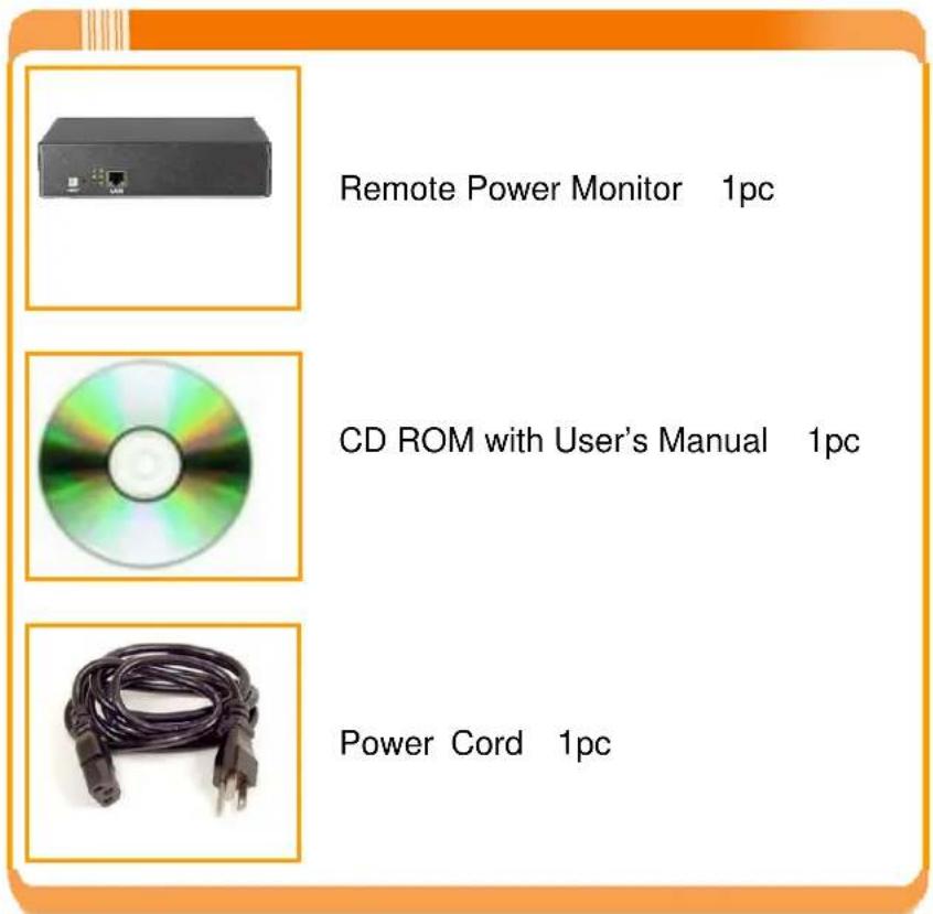
1-6 Receiving Inspection
After removing your RPM from its carton, it should be inspected for damage that may have occurred in shipping. Immediately notify the carrier and place of purchase if any damage is found. Warranty claims for damage caused by the carrier will not be honored. The packing materials that your RPM was shipped in are carefully designed to minimize any shipping damage. In the unlikely case that the RPM needs to be returned to MINUTEMAN, please use the original packing material. Since MINUTEMAN is not responsible for shipping damage incurred when the system is returned, the original packing material is inexpensive insurance.
PLEASE SAVE THE PACKING MATERIALS!
2. Installation and Setup
2-1 Hardware Installation
The RPM1521E is intended to be installed in a temperature controlled environment that is free of conductive contaminants. Select a location, which will provide good air circulation for the RPM1521E at all times. Avoid locations near heating devices, water or excessive humidity, or where the RPM1521E is exposed to direct sunlight. Route power cords so they cannot be walked on or damaged.
CONNECTING THE RPM1521E TO AN AC SOURCE
CAUTION - To reduce the risk of fire, connect only to a circuit provided with 20 amperes maximum branch circuit over-current protection in accordance with the National Electric Code, ANSI/NFPA 70. Plug the RPM1521E into a two pole, three wire, grounded receptacle only. Do not use extension cords, adapter plugs, or surge strips. Do not plug the RPM1521E to the output of a Simulated Sine Wave UPS.
- Connect the power cord to the power inlet on the RPM and to the utility service.
- Plug the equipment into the output receptacles.
- Connect the Ethernet cable to the Ethernet port.
- Connect the Temperature probe (optional)
- Turn the power switch to the ON position.
This is a typical application for the RPM1521E.
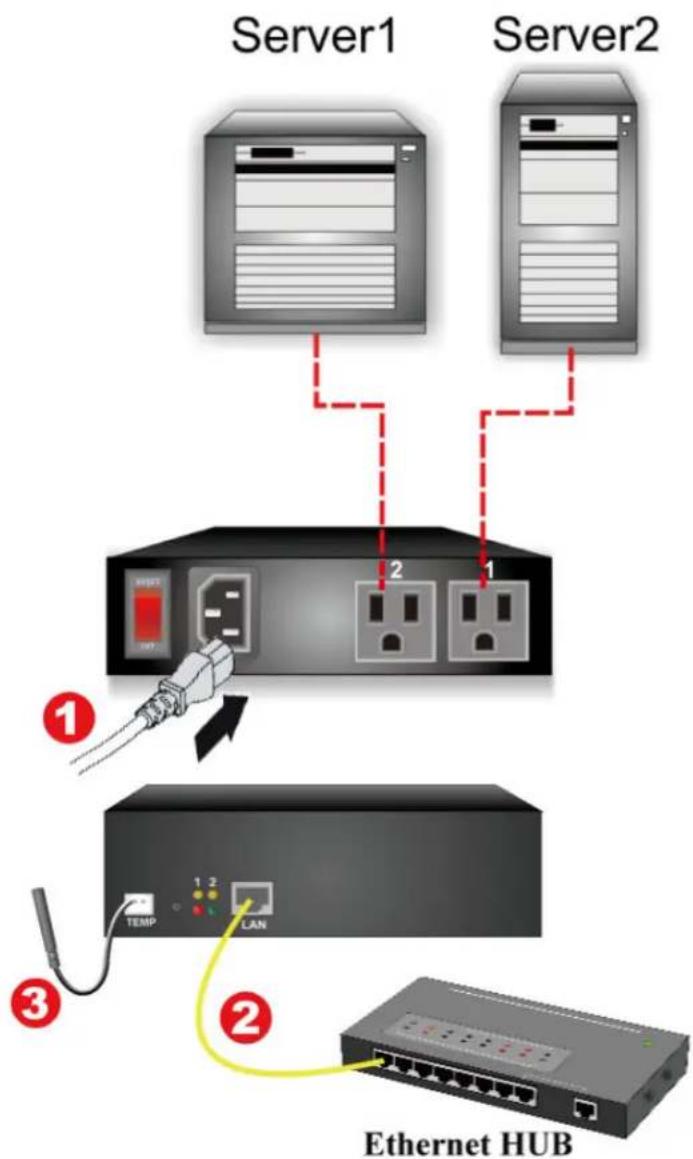
| 1 | Input utility power |
| 2 | LAN / WAN connection |
| 3 | Temperature Probe (optional) |
2-2 Setup-Procedure
The minimum requirement to operate the RPM1521E is to setup the IP Address, subnet mask, and the gateway. DHCP is enabled as the default. Contact your system administrator or use the IP Search Utility program (on the CD) to obtain the IP address. If there is no DHCP server the default settings are as follows:
The default settings are:
IP address: 192.168.1.10
Subnet mask: 255.255.255.0
Gateway address: 192.168.1.1
Account name: admin (lower case)
Password: admin (lower case)
There are two ways to perform the Setup-Procedure:
-
Open a web browser and input either the default IP address or the IP address obtain from DHCP. Then Setup Wizard will open. Follow the steps to setup the RPM1521E.
-
Use the IP Search Utility program (on the CD). The IP Search Utility program supports most Windows Operating Systems.
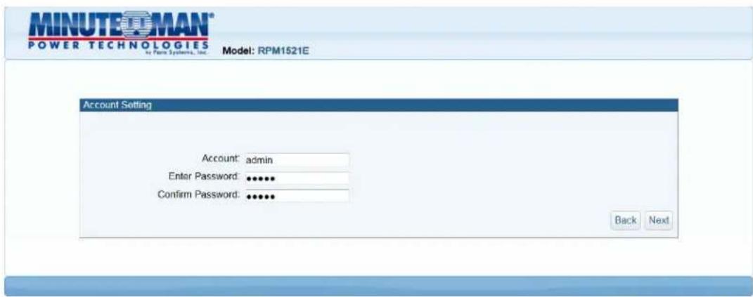
Setup Procedure using the Setup Wizard
-
Open a Web browser and input the IP address for the RPM1521E.
-
The Setup Wizard will open.
-
Enter the default Account Name (admin). Enter the default Password (admin). Confirm the Password and then click on the Next button. The Password can be changed now or later under the Account tab.
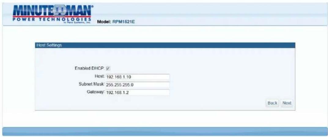
- Configure the Host settings and the click on the Next button.
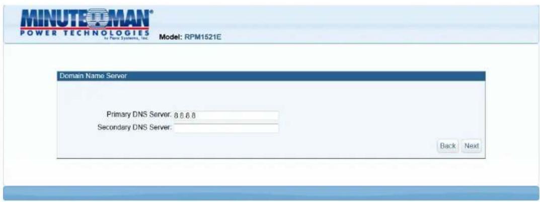
- Configure the DNS setting and then click on the Next button.
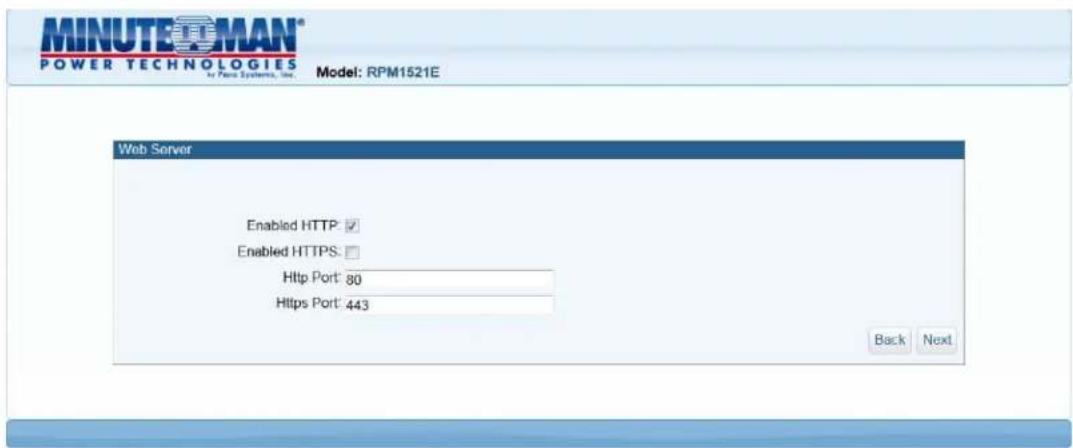
- Configure the Web Server setting and then click on the Next button.
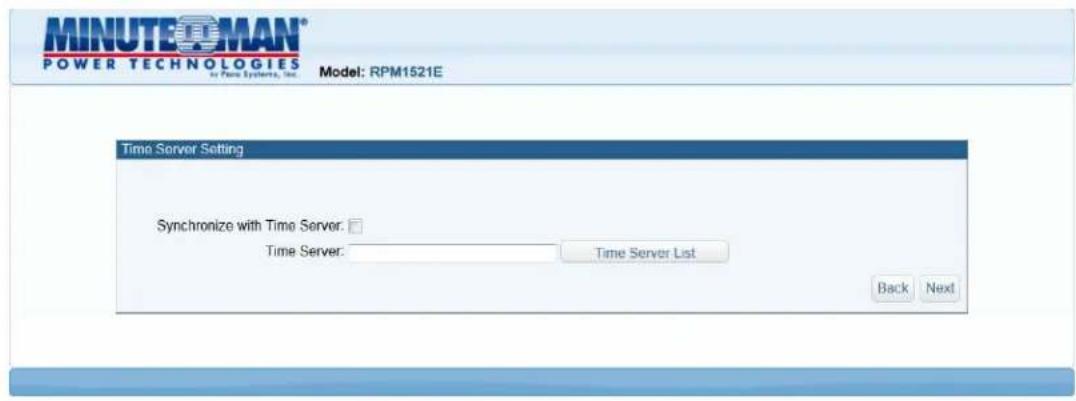
- Configure the Time Server setting and then click on the Next button.
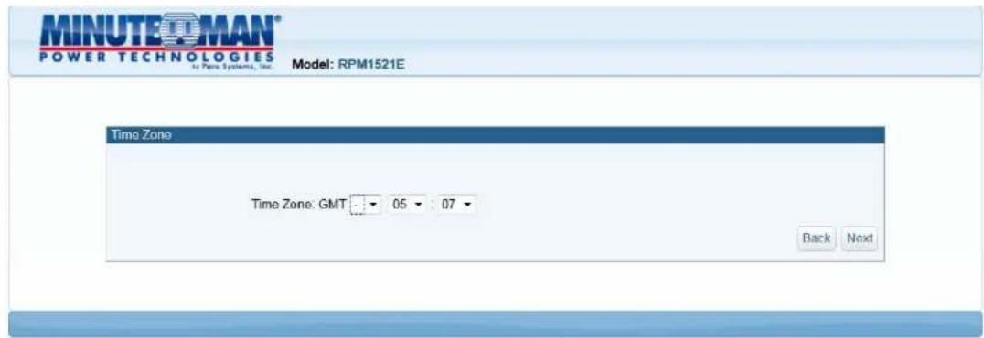
- Configure the Time Zone setting and then click on the Next button.
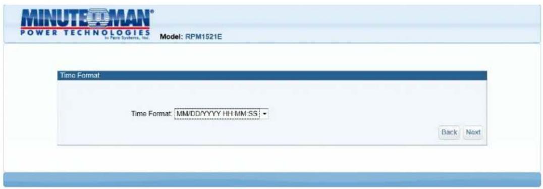
- Select the Date and Time format and then click on the Next button.
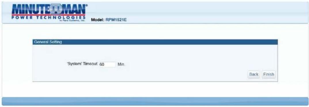
- Configure the System Timeout time and then click on the Next button. The system will reboot to save all of the changes. Once the system is finished rebooting the Login screen will open.
- This completes the initial Setup-Procedure of the RPM1521E.
- Now you are able to monitor and control the RPM1521E via a Web browser. See Section 3 for the Web Operation.
Setup Procedure using the IP Search Utility program
- The workstation and the RPM1521E must be in the same LAN to perform the Setup-Procedure.
- The Windows Firewall must be turned off to operate the IP Search Utility program.
- From the Start menu select the Control Panel.
- Select the Windows Firewall.
- Select Off and then click the OK button.
- Put the RPM1521E's CD (provided) in the CD-ROM drive.
- Launch the IP Search Utility program.
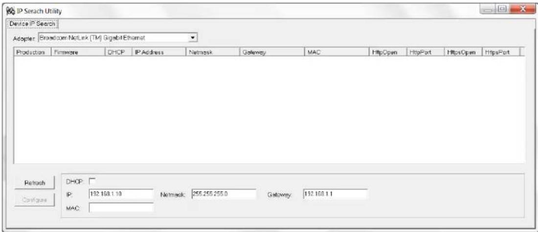
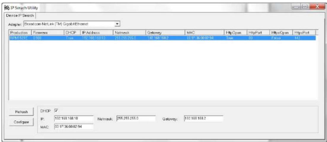
- Click on the Refresh button to search for all of the RPM1521E's in the LAN. A list of the RPM1521Es will be displayed.
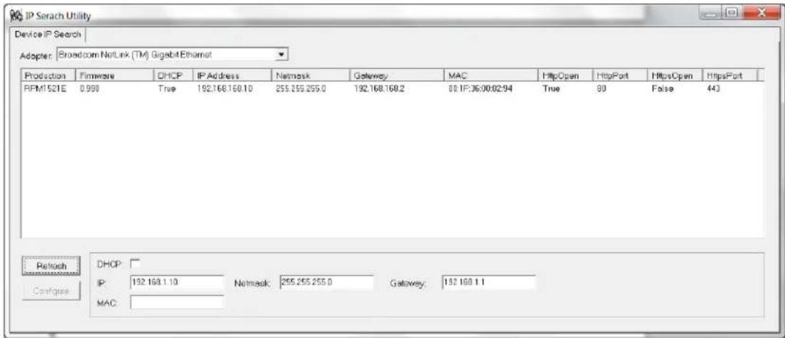
- Select an RPM1521E from the list that you want to configure. Make the changes to the IP address, the Gateway and the NetMask (Subnet) and then click on the Configure button. Click on the Refresh button and verify the changes.
- Repeat Step number 8 and 9 for all of the RPM1521Es in the list.
- Once all of the RPM1521Es are configured, close the IP Search Utility program and turn the Windows Firewall back on.
- This completes the initial Setup-Procedure of the RPM1521E.
- Now you are able to monitor and control the RPM1521E via a Web Browser.
3. Web Operation
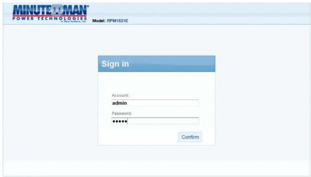
3-1 System Login
- Open a Web Browser (Internet Explorer, Firefox, etc.).
- Enter the RPM1521E's IP Address.
- Enter the Account name (admin) and Password (admin).
NOTE: The Account name and the Password are lower case.
3-2 Monitor Tab
The Monitor tab allows the user to monitor and configure the outlets and the external temperature probe.
3-2-1 Power Switch Operation

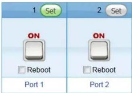
Clicking on the ALL ON button will turn ON both of the outlets. Clicking on the ALL OFF button will turn OFF both of the outlets.
Clicking on one of the bottom buttons will turn ON that individual outlet or turn OFF that individual outlet. If you want to reboot the individual outlet check the Reboot box and then single click with the left mouse button on the bottom button to reboot the outlet.
Set Button: Click on the Set button located on the top corner of the outlet to setup that individual outlet. When the Set button is green, the outlet is ready to be configured.
NOTE: Each outlet must be individually configured.
Button Illustration:

ON

OFF

Not Authorized

No Power
3-2-2 Power
The Power tab allows the user to configure the power ON/OFF delay time.
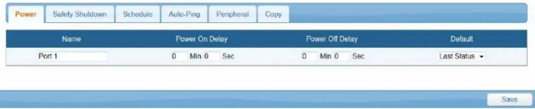
Name: The users can assign a name to each individual outlet. This allows the system administrator and/or manager to easily distinguish between the equipment that is connected to the outlets.
Power On Delay: Each outlet can be programmed to startup at different time intervals instead of both of them starting up at the same time.
Power Off Delay: Each outlet can be programmed to shutdown at different time intervals instead of shutting both of them down at the same time.
Default: The default status of the each outlet can be configured.
Save: Once the setup is complete click the Save button to save all of the changes.
3-2-3 Safety Shutdown
This tab is for setting up the RPM1521E to send the shutdown command to the Shutdown Agent software on the computer.

MAC: Enter the computer's MAC address that you want to shutdown.
Delay Delivery: After delay delivery time, the WOL command will be sent to the computer based on one of the Actions configured in Power Tab, Schedule Tab, or the Auto-Ping Tab.
Computer Name: Prior to the execution of safety shutdown, the RPM1521EShutDownService-2020-windows-installer program must be installed on the computer. Once in installed, select the computer to be shutdown from the drop-down list. See Appendix A1 for Shutdown Agent Installation.
3-2-4 Schedule
Schedule the outlet to turn ON/OFF or Reboot on a certain day at a specific time.

Period: An Action can be schedule to occur yearly, monthly, weekly or daily at a specific time for each individual outlet.
Time: Set the time (hours and minutes) when you want the Action to occur.
Action: Set the action you want the outlet to perform, ON, OFF or Reboot.
Delete: To delete a schedule, double-click on the "X".
Add: Click the ADD button to add this action.
Save: Once the setup is complete click the Save button to save all of the changes.
3-2-5 Auto-Ping
The RPM1521E can be setup to ping an IP-addressable device and detect when that device has stopped communicating. If the Reboot action is selected the power to the connected device will be cycled OFF and then ON. After the preset time the Auto-Ping function will restart.
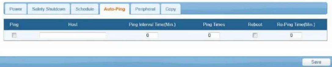
Ping: Check this box to enable the Auto-Ping function.
Host: Enter the IP address of the device to ping.
Ping Interval Time: Set the time Interval to PING the connected device.
Ping Times: If a device fails to respond to a ping continuously and exceeds the preset time, the RPM1521E will notify the selected personnel via email or SMS.
Reboot: Check this box to reboot the outlet for the failed connected device.
Re-Ping Time: The time interval before restarting the Auto-Ping function after the connected device has been rebooted.
Save: Once the setup is complete click the Save button to save all of the changes.
3-2-6 Peripheral
This tab is for setting up an action based on the temperature of the Device and/or the External Temperature Probe.
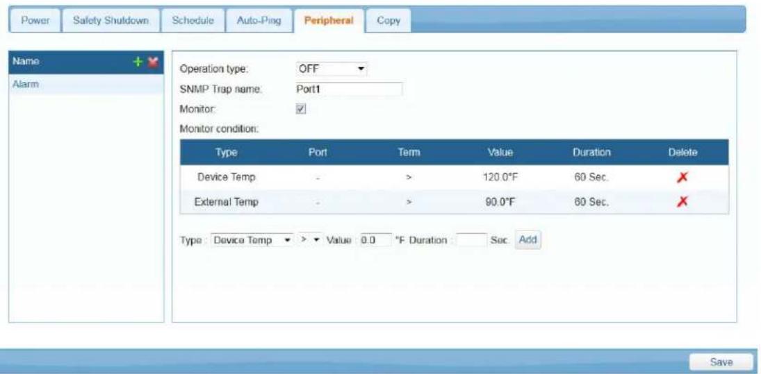
Name: Add a command name. Clicking on the green plus sign next to the name will open a pop up menu to enter the name.
Operation type: Choose the action for the specific output, Off, Reboot or Short on.
SNMP Trap name: The specify name of the alarm.
Monitor: Check to enable the commands and monitoring.
Monitor condition
Type: Use drop down list to select the Device Temperature or External Temperature.
Port: Select which Port of the RPM1521E to monitor and control.
Term: You may choose the terms of >, < or =.
Value: Set the temperature threshold to trigger the command.
Duration: Set the time for the RPM1521E to wait before issuing the command.
ADD: Click the ADD button to add this action.
Delete: Clicking the 'X' icon will delete the command.
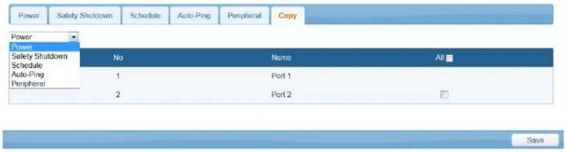
3-2-7 Copy
After configuring one of the outlets you can copy the same configuration to the other outlet.
3-2-8 Temperature
The RPM1521E has an optional External Temperature Probe and it also reports its internal (Device) temperature.
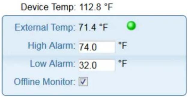
Device Temp: Internal temperature of the RPM1521E.
External Temp: When External Temperature Probe is connected, it will display the temperature.
High Alarm: When the external temperature exceeds this value, an alarm (email, SMS, Trap) will occur. Only applies to the External Temperature Probe.
Low Alarm: When the external temperature is lower than this value, an alarm (email, SMS, Trap) will occur. Only applies to the External Temperature Probe.
Offline Monitor: When Enabled, verifies the Temperature Probe is connected.
Probe state: External Temperature Probe has 3 states:
Monitor Normal: The "Offline Monitor" is checked. The external temperature is not higher than the "High Alarm" setting or is not lower than the "Low Alarm" setting.
Monitor Alert: The "Offline Monitor" is checked. The external temperature is higher than the "High Alarm" setting or is lower than the "Low Alarm" setting.
Monitor Off-line: The "Offline Monitor" is checked. The temperature probe is not connected to the RPM.
3-3 System Tab
3-3-1 Network
The RPM1521E can be configured with a Static IP address or setup to use DHCP. The default setting is DHCP Enabled. If there is no DHCP service then the following Static addresses are the default settings:
Static IP address: 192.168.1.10
Subnet mask: 255.255.255.0
Gateway address: 192.168.1.1
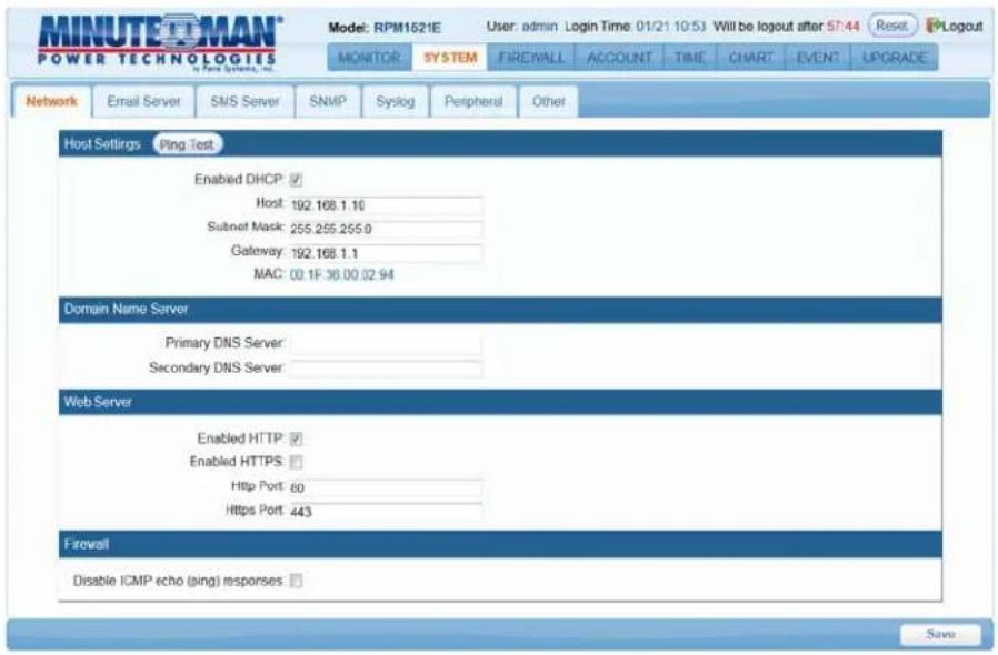
Ping Test: This will validate the network connection.
Host: Enter the IP address.
Subnet Mask: Enter the Subnet Mask.
Gateway: Enter the Gateway address.
Primary DNS Server: Enter your primary DNS server.
Secondary DNS Server: Enter your secondary DNS server (if required).
HTTP: Enabling or disabling the HTTP connection with the RPM1521E.
HTTPS: Enabling or disabling the HTTPS connection with the RPM1521E.
HTTP Port: The user may change HTTP port to use a port number other than standard HTTP port (80).
HTTPS Port: The user may change HTTPS port to use a port number other than standard HTTPS port (443).
Disable ICMP echo (ping) responses: When disabled (checked) the RPM1521E will not respond to ping request.
Save: Once the setup is complete click the Save button to save all of the changes.
3-3-2 Mail Server
This menu allows the administrator to configure the email setting to send notifications once an event has occurred. The RPM1521E does support secure email (TLS) such as Gmail.
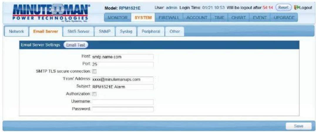
Email Test: This is used to verify that the email works properly.
Host: Enter the Hostname or IP address of the SMTP Mail Server that will be used to send emails. If entering a Hostname, you are also required to enter the DNS Address.
Port: Enter the port number for the SMTP server. The default port is 25.
SMTP TLS secure connection: Check this box if using secure email.
From Address: This must be a legitimate email address.
Subject: When an event occurs the RPM1521E will send an email notification. The subject line can be setup to easily identify that device.
Authorization: Check this box if the Mail Server requires authentication to send emails.
Username: Enter the account name if SMTP authentication is required.
Password: Enter the password if SMTP authentication is required.
Save: Once the setup is complete click the Save button to save all of the changes.
NOTE: The email recipient's email address must be entered in the Account Tab. See section '3-5 Account Tab'.
3-3-3 SMS Server
This menu allows the administrator to configure the SMS setting to send notifications once an event has occurred.
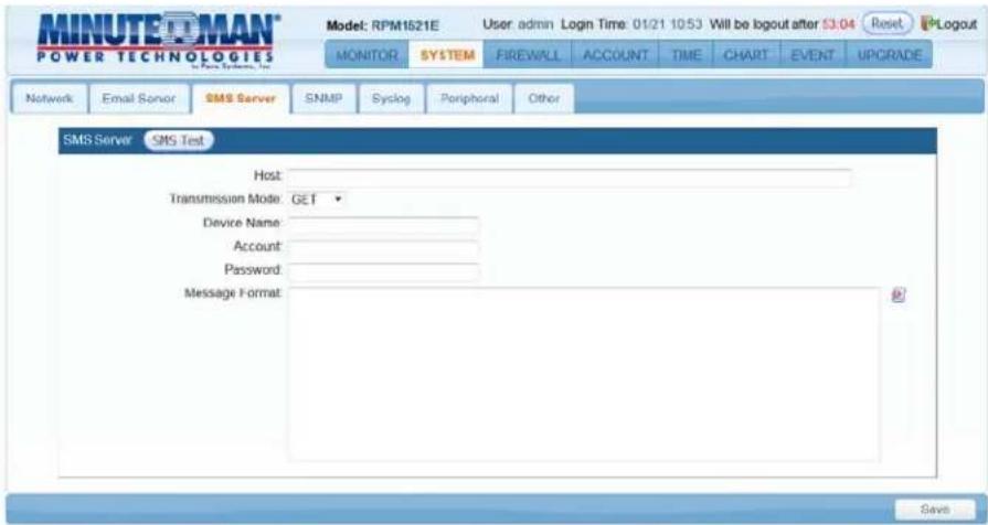
SMS Test: This is used to verify that the SMS works properly.
Host: Enter the SMS server IP address or the host name.
Transmission Mode: Select the correct protocol based on your specific ISP to transmit the SMS message.
Device Name: When an event occurs the RPM1521E will send an SMS notification. The device name will identify the device.
Account: Enter the account name if required.
Password: Enter the password if required.
Message Format: The RPM1521E will auto load the following information username, password, number, main host and message content based on the commands enter into the message format box. Clicking on the icon to the right of the message format box shows the options for the message format.
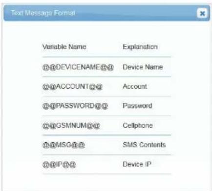
Save: Once the setup is complete click the Save button to save all of the changes.
NOTE: The SMS recipient's cell phone number must be entered in the Account Tab. See section '3-5 Account Tab'.
3-3-4 SNMP
This menu allows the administrator to configure the RPM1521E to send SNMP Traps to Network Management Stations (NMS).
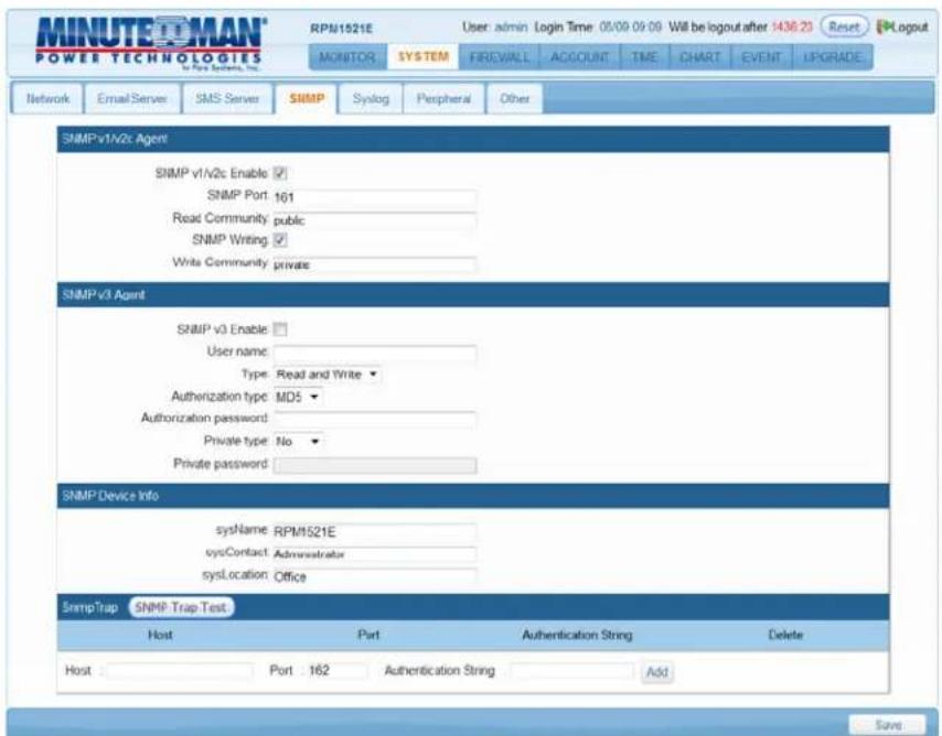
SNMP v1-v2c Enable: Check the box to enable SNMP v1 & v2c Traps.
SNMP Port: Set the SNMP Access port. The default is 161.
Read Community: A low-level password to restrict SNMP access.
SNMP Writing: Enables the Write Community
Write Community: A high-level password to restrict SNMP access.
SNMP v3 Enable: Check the box to enable SNMP v3 Traps.
Username: Enter the username.
Type: Enter the access type.
Authorization type: Select the authentication type.
Authorization password: Enter the password.
Private type: Select if private type or not private type.
Private password: Enter the password, if required.
SysName: Enter the name of the SNMP device.
SysContact: Enter the name of the System Contact.
SysLocation: Enter the location of the SNMP device.
SNMP Test: This is used to verify that the SNMP Trap notification works properly.
Host: The IP address of the NMS where the SNMP Traps should be sent.
Port: The port that the NMS will use to receive the SNMP Traps. The default value is 162.
Authentication string: Enter the authentication string to access SNMP Trap, if required.
ADD: Click the ADD button to add this action.
Save: Once the setup is complete click the Save button to save all of the changes.
3-3-5 Syslog
This menu allows the administrator to configure the RPM1521E to send Systems logs.
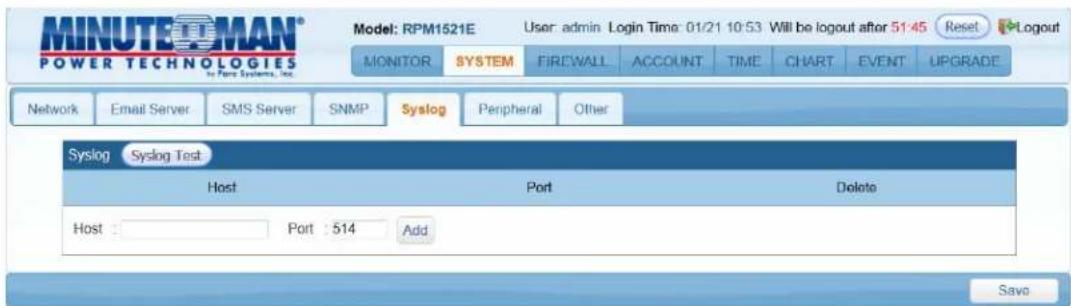
SYSLOG Test: This is used to verify that the SYSLOG works properly.
Host: The IP address of the Server where the System Logs should be sent.
Port: The port that the Server will use to receive the System Logs. The default port is 514.
ADD: Click the ADD button to add this action.
Save: Once the setup is complete click the Save button to save all of the changes.
3-3-6 Peripheral
This menu allows the administrator to configure the temperature scale for the Device and the External Temperature Probe.
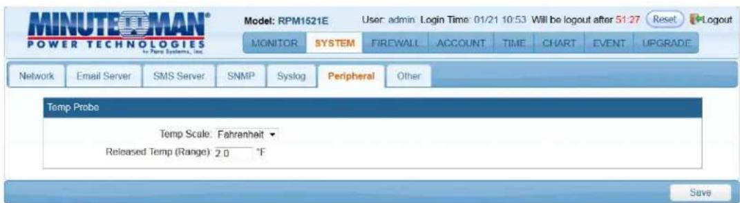
Temp Scale: Choose either Celsius or Fahrenheit for the Device and External temperature probe to report.
Released Temp (Range): Once the External temperature drops below the High Alarm setting by the amount in the Released Temp (Range) the alarm will be cancelled. Once the External temperature rises above the Low Alarm setting by the amount in the Released Temp (Range) the warning will be cancelled. This only applies to the External Temperature Probe.
3-3-7 Other
This menu allows the administrator to configure the General and Security settings.
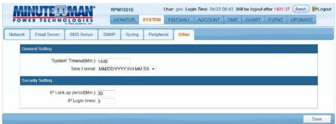
System Timeout (Min): The time interval between no activity and when the user will be logged out.
Time Format: There are three choices for the time and date format:
YYYY/MM/DD/HH/MM/SS
MM/DD/YYYY/HH/MM/SS
DD/MM/YYYY/HH/MM/SS
IP Lock-up period (Min): The amount of time the user will be locked out before being able to login again.
IP Login times: The number of attempts logging in (incorrectly) before the system locks you out.
Save: Once the setup is complete click the Save button to save all of the changes.
3-4 Firewall Tab
3-4-1 IP Filter
This menu allows the administrator to configure the user's privileges and prevent unauthorized access to the RPM1521E through the network.
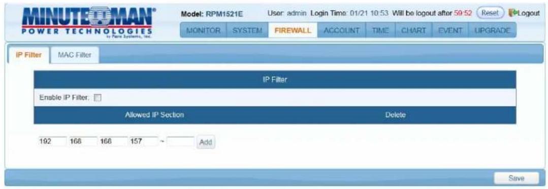
Enable IP Filter: Check the box to enable the IP filter.
Allowed IP Section: The first four sections are the beginning of the IP range. The last section is the ending of the IP range, which the administrator has given specific rights to certain users to access the RPM1521E. Example to authorize the IP ranges of 192.168.1.100 to 192.168.1.200, input 192.168.1.100 in the first four sections and then input 200 in the last section. If you only want to authorize one IP address, then input 192.168.1.100 in the first four sections and then input 100 in the last section. The default IP address range is the IP address of the computer that you initially use to view the RPM1521E.
ADD: Click the ADD button to add this action.
Delete: To delete a specific IP address click on the "X".
Save: Once the setup is complete click the Save button to save all of the changes.
3-4-2 MAC Filter
This menu allows the administrator to configure the user's privileges and prevent unauthorized access to the RPM1521E through the network.
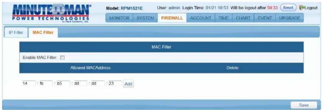
Enable MAC Filter: Check the box to enable the MAC filter.
Allowed MAC Address: The administrator can give specific rights to certain users to access the RPM1521E. Enter the MAC address of the user that you want to have access to the RPM1521E. The default MAC address is the MAC address of the computer that you initially use to setup the RPM1521E.
ADD: Click the ADD button to add this action.
Delete: To delete a specific MAC address click on the "X".
Save: Once the setup is complete click the Save button to save all of the changes.
3-5 Account Tab
This menu allows the administrator to setup authorized user accounts and other privileges. The administrator can assign specific access levels for each user account. Example: The administrator can assign user "A" to have access to outlet number 1 and receive email notifications when an event occurs to that specific outlet.

Modify: Click on the Modify button to make changes to a specific account.
Delete: To delete a specific account click on the "X".
Add: Click on the Add button to add additional users.
Basic Info Tab
This menu allows the administrator to setup the account names and the passwords for each authorized user. The administrator can assign specific access levels for each user account.
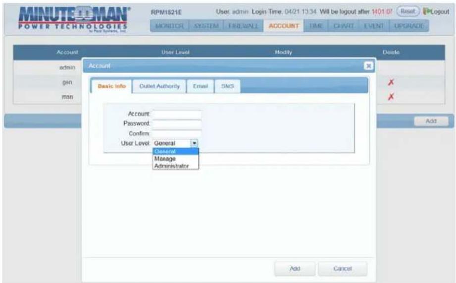
Account: Enter the account name for the user.
Password: Enter the password for the user.
Confirm: Confirm password for the user.
User Level: There are three different user levels:
- Administrator: Highest level of authority. Can change System and Parameter settings and has outlet control.
- Manage: Second level of authority. Can change Parameter settings and has outlet control.
- General: Outlet control only.
ADD: Once the setup is complete click the ADD button to save all of the changes.
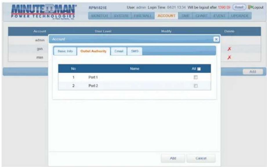
Outlet Authority Tab
This menu allows the administrator to setup the outlet authority for each account.
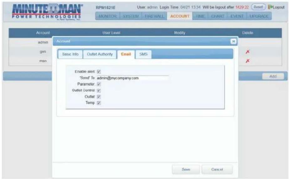
Email Tab
This menu allows the administrator to setup the email recipient for each account and which alert they will receive.
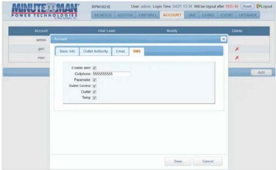
SMS Tab
This menu allows the administrator to setup the SMS recipient for each account and which alert they will receive.
3-6 TimeSync Tab
This menu allows the administrator to set the date and time for the RPM1521E.
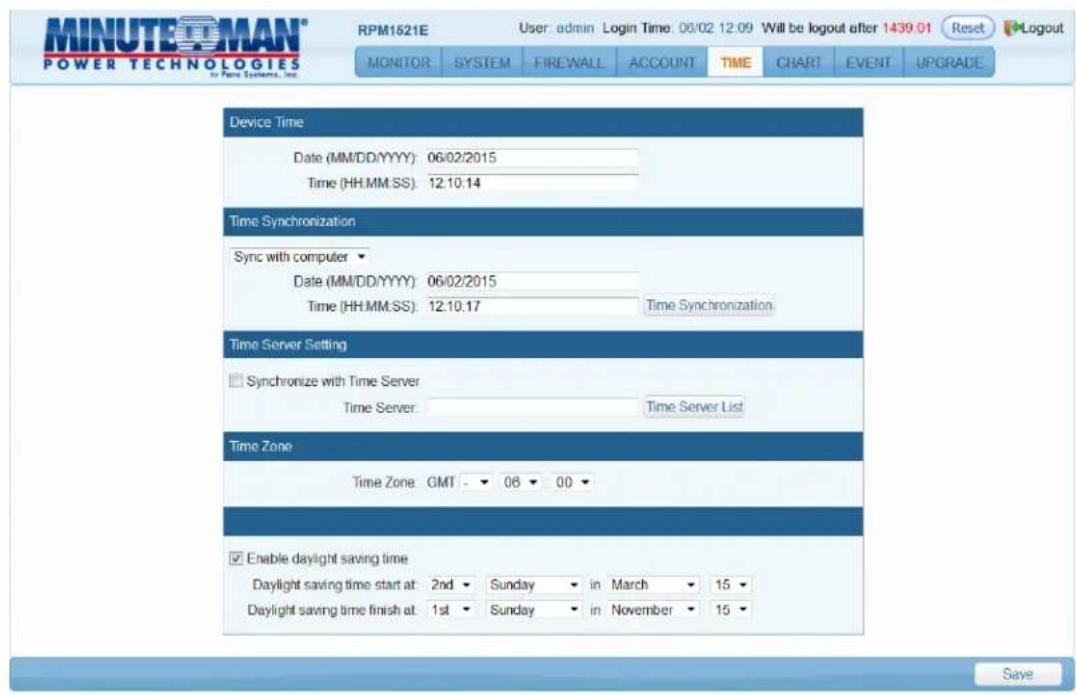
Device Time:
The device time cannot be manually changed. The device time will be automatically changed when using the Time Synchronization or a Time Server.
Time Synchronization:
Sync with computer: Select Sync with computer to synchronize the RPM1521E's date and time with the computer.
Date: The current PC system date.
Time: The current PC system time.
Time Synchronization Button: Once you select Sync with computer click on the Time Synchronization button.
Manual Setting: Set the date and time manually.
Time Server Setting:
Check the Synchronize with time Server button. Then manually enter the time server IP address or make a selection from the Time Server List.
Time Zone: Set the GMT time zone for your specific area so that the date and time will display correctly.
Enable daylight saving time: This option is used to setup daylight saving time. During the period of daylight saving time, the time will be automatically adjusted.
Save: Once the setup is complete click the Save button to save all of the changes.
3-7 Chart
This menu allows you to see the Device and External Temperature in a graphical format. Moving the cursor over the chart will display the date, time and the temperature in a text box.
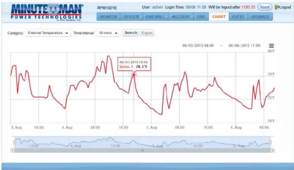
line
| Time | Value | | ---------- | ------- | | 08/04/2015 | 78.1°F |Category: Select either the Device temperature or the External temperature to view.
Time Interval: Select the time interval to view and log the temperature.
Search: Once the category selection has been made click on the Search button to load the graph.
Export: The data for each category can be exported. The data is exported in csv format.
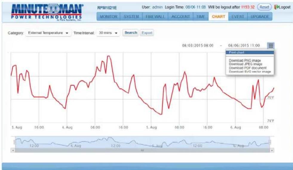
line
| Date | Price | | ---------- | ----- | | 08/03/2015 | 74°F |Print Chart: The chart can be printed or downloaded as an image by using the print icon on the right hand side.
3-8 Event Tab
This menu displays the events that have occurred with the RPM1521E.
![MINUTEOMAN® POWER TECHNOLOGIES To Pure Systems, Inc. Model: RPM1521E User: admin Login Time: 01/21 15:10 Will be logout after 57:04 Reset Logout MONITOR SYSTEM FIREWALL ACCOUNT TIME CHART EVENT UPGRADE Event Record Time Type Message 1 01/21/2015 15:10:18 User[admin][192.168.168.157]login 2 01/21/2015 14:54:35 User[admin][192.168.168.157]logout 3 01/21/2015 13:46:37 User[admin][192.168.168.157]login 4 01/21/2015 12:33:50 User[admin][192.168.168.157]logout 5 01/21/2015 12:32:33 User[admin][192.168.168.157]login 6 01/21/2015 12:32:17 Reboot software Page 1 of 1 View 1 - 50 of 0](/content/2026/05/1128219/images/85a8869d7d47b9983a1d37e31699dd2e02a91c4159705387329f6419190300e2.jpg)
Refresh: Click on the Refresh icon to refresh the screen.
Download: Click on the Download icon to save the event log information. The event log is saved in .txt format.
Delete: Click on the Delete icon to delete the Event logs.
3-9 Upgrade Tab
This menu allows the administrator to upgrade the firmware and download the configuration (settings) file of one RPM1521E and then upload it to another RPM1521E.
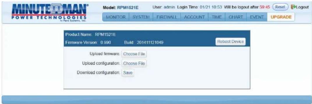
Upload firmware: Click on Choose File and select the proper firmware file. The firmware file is in .bin format. Once the correct firmware file has been selected the Choose File button will change to Upload. Click on the Upload button to start the firmware upgrade process, this will take approximately two minutes to complete. Once the upgrade is complete the RPM1521E will reboot to save the changes.
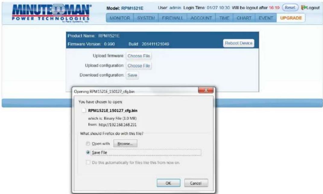
Download configuration: Click on the Save button. Select the location to save the file. The file is saved as cfg.bin
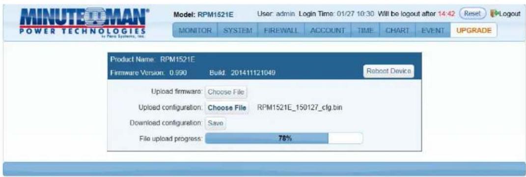
Upload configuration: Open the RPM1521E that you want to configure. Click on the Choose File button. Select the proper configuration file (cfg.bin). Click the Open button and the uploading process will start. Once the upload is complete the RPM1521E will reboot to save the changes.
Appendix
A1 Shutdown Agent Installation
The Shutdown Agent is a service that runs in the background. Installing the Shutdown Agent software is optional. The Shutdown Agent is installed on the computer that you want the RPM1521E to shutdown based on a specified event. The WOL command will be sent to the computer based on one of the Actions configured in Power Tab, Schedule Tab, or the Auto-Ping Tab.
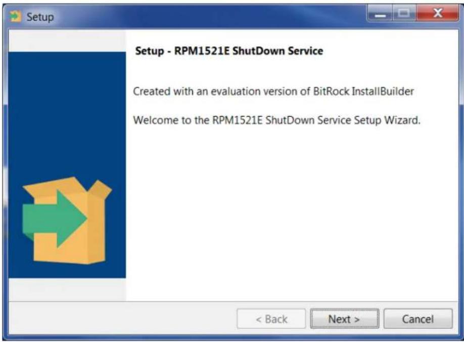
- Execute the RPM1521EShutDownService-2020-windows-installer.exe to run the setup program.
- Click on the "Next" button to continue with the installation or click on the "Cancel" button to stop the installation.
- The destination location can be changed by clicking on the "Browse" button or click on the "Next" button to install the software in the default location.
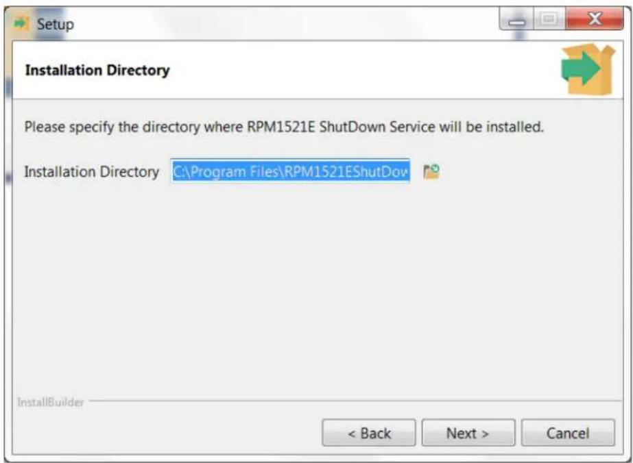
- Click on the "Next" button to continue with the installation.
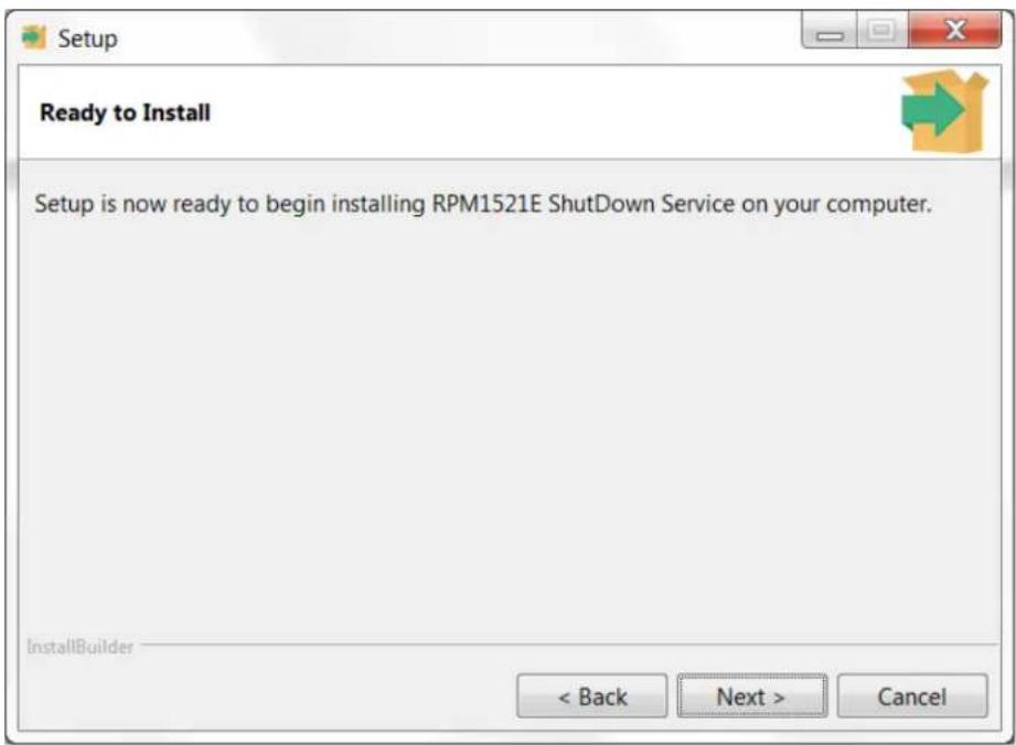
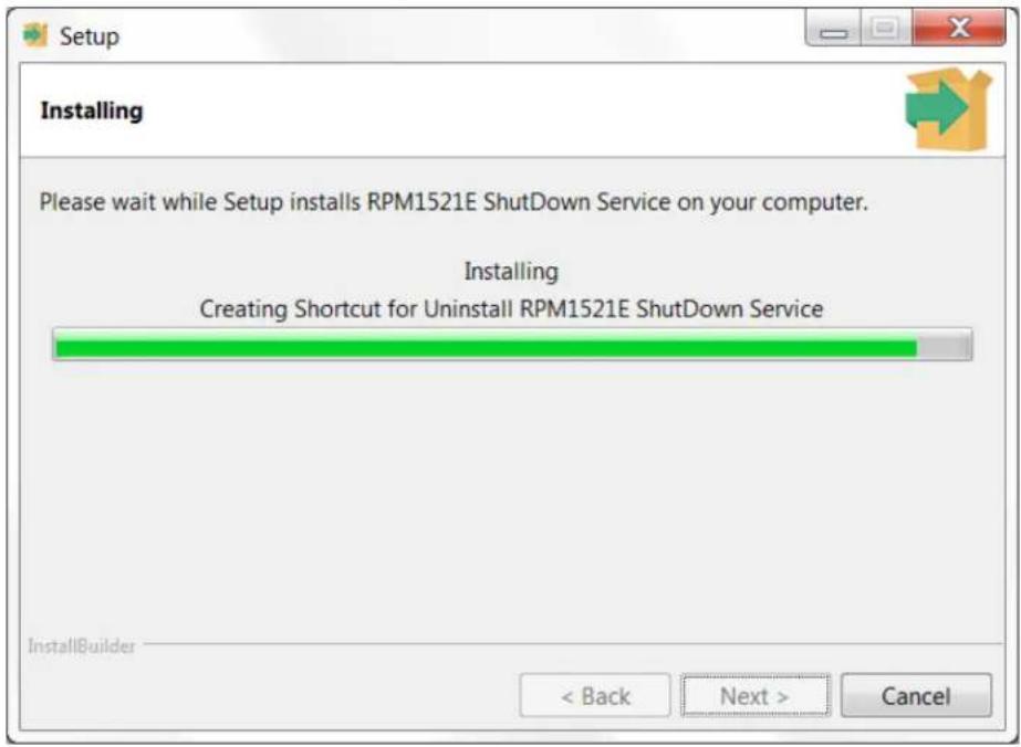
- The Shutdown Agent is being installed.
- Click on the "Finish" button to complete the installation
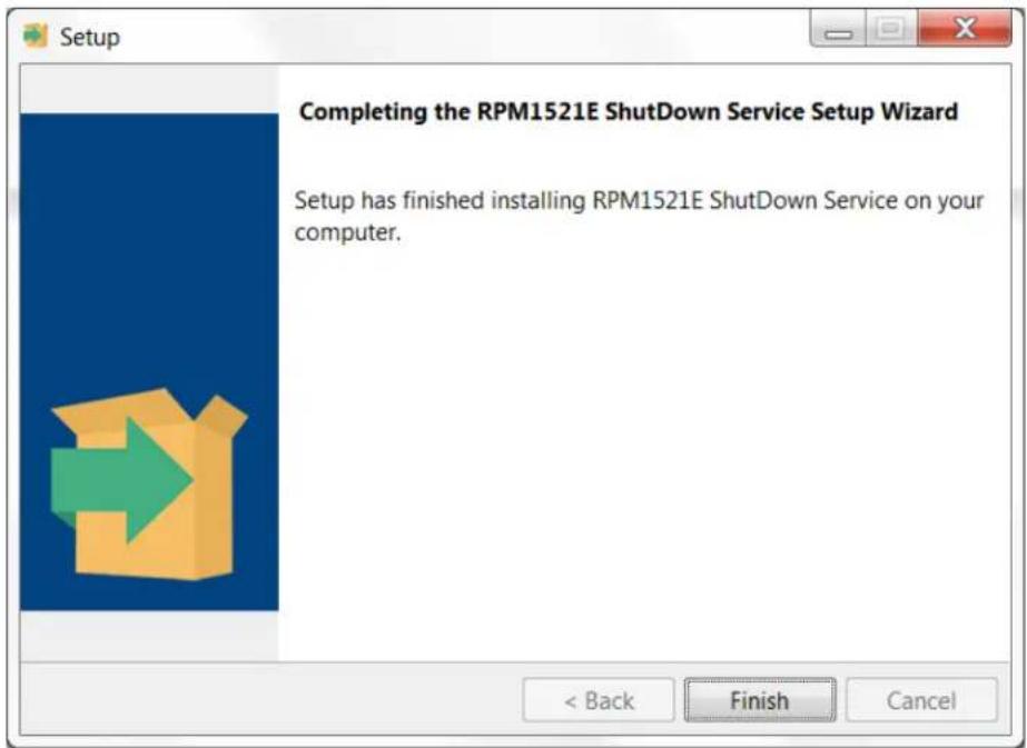
- The computer must be restarted to save all of the changes. The Shutdown Agent will automatically startup once the computer restarts and on all future startups.

- After the installation is complete, in the lower right-hand corner of the taskbar the icon for the Shutdown Agent will be displayed.

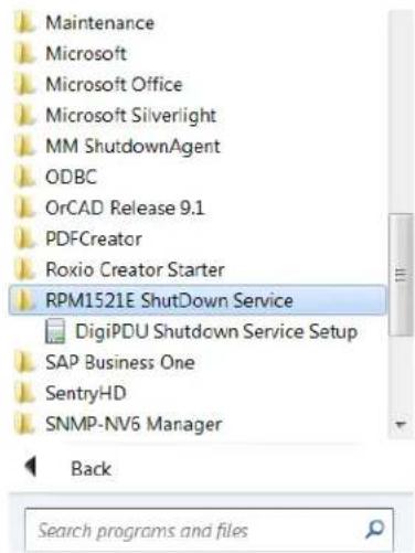
You can also start the program by going to the Start menu.
Start -> All Programs -> RPM1521E ShutDown Service (folder) -> Shutdown Service
As shown below,
- Right click on the Shutdown Agent icon and then select "Setup(s)" in the menu.

- After selecting "Setup(s)", the following screen will open.
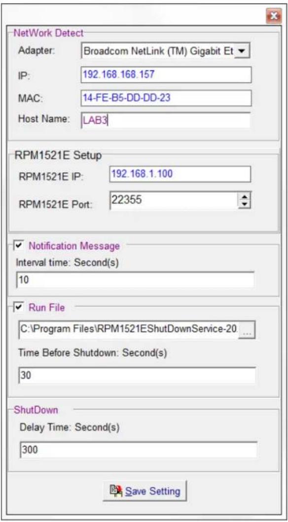
Network Detect
Adaptor: Select the computer that will that receive the shutdown command.
IP: The IP address of computer that will that receive the shutdown command.
MAC: The MAC address of computer that will that receive the shutdown command.
Host Name: The host name of the computer that will receive the shutdown command.
RPM1521E Setup
RPM1521E IP: The IP address of the RPM1521E that will trigger the Shutdown Agent.
RPM1521E Port: The port used for the communication between the RPM1521E and the computer with the Shutdown Agent. The default port is 22355.
Notification messages: A window will pop up to notify the user of the Shutdown Action.
Delay Time: The amount of time before the pop up window will open after receiving the Shutdown command.
Run File: The user can create a batch file to run before the computer shuts down. The batch file will be triggered once the Shutdown command from the RPM1521E has been received.
Delay Time: The amount of time before running the batch file.
Save Setting: Click on the "Save Settings" button to save all of the settings. The Setup menu will close. The icon for the Shutdown Agent will be in the lower right-hand corner of the taskbar.
NOTE: Once the installation and configuration of the Shutdown Agent is complete; open the RPM1521E to configure the Safety Shutdown settings. See section 3-2-3 Safety Shutdown.
A2 Reset to Default
If you forgot the password and/or the user name the RPM1521E can be reset back to the factory default settings.
The reset button is located in the small hole next to the reset Red LED. Insert a pointed object like a paper clip into this hole. Gently push and hold the reset button for at least 3-seconds, but less than 10-seconds, the Red LED will start flashing, and then release the reset button.
DHCP will be enabled and the static IP address will be reset back to 192.168.1.10 The user name and password will be reset back to admin.
All of the other setting will be unchanged.
To clear all setting press and hold the reset button for more than 10-seconds, the Red LED will turn on solid, and then release the reset button.
A3 Obtaining Service
For Technical Support on the Web, please visit the Support section of our Web site or visit our online Discussion Forum.
-
Verify there are no tripped circuit breakers. A tripped circuit breaker is the most common issue.
-
Call your dealer for assistance. If you cannot reach your dealer, or if they cannot resolve the issue call or fax the Technical Support department at the following numbers; Voice phone (972) 446-7363, FAX line (972) 446-9011 or visit our Web site at www.minutemanups.com the "Discussion Board". Before calling the Technical Support Department have the following information available:
a) Contact name and address.
b) Where and when the unit was purchased.
c) All of the model information about your unit.
d) The serial number of your unit.
e) Any information on the failure, including LEDs that may be illuminated or error codes displayed.
f) A description of the protected equipment including model numbers, if possible.
g) A technician will ask you for the above information and if possible, help solve the issue over the phone. In the event that the unit requires factory service, the technician will issue you a Return Material Authorization Number (RMA #). NOTE: We must have the model number and the serial number of the product to issue the RMA #.
h) If the unit is under warranty, the repairs will be done at no charge. If the unit is not under warranty there will be a charge for the repair.
- Pack the unit in its original packaging. If the original packaging is no longer available, ask the Technical Support Technician about obtaining a new set. It is important to pack the unit properly in order to avoid damage in transit. Never use Styrofoam beads for a packing material.
a) Include a letter with your name, address, day time phone number, RMA number, a copy of your original sales receipt, and a brief description of the problem.
-
Mark the RMA # on the outside of all packages. The factory cannot accept any package without the RMA # marked on the outside.
-
Return the unit by insured, prepaid carrier to:
Para Systems Inc.
MINUTEMAN UPS
1809 W. Frankford Road, Suite 150
Carrollton, TX 75007
ATTN: RMA #
A4 Limited Product Warranty
Para Systems, Inc. (Para Systems) warrants this equipment, when properly applied and operated within specified conditions, against faulty materials or workmanship for a period of three years from the date of purchase. For equipment sites within the United States and Canada, this warranty covers depot repair or replacement of defective equipment at the discretion of Para Systems. Depot repair will be from the nearest authorized service center. The customer pays for shipping the product to Para Systems. Para Systems pays ground freight to ship the product back to the customer. Replacement parts and warranty labor will be borne by Para Systems. For equipment located outside of the United States and Canada, Para Systems only covers faulty parts. Para Systems products that are depot repaired or replaced pursuant to this warranty shall only be warranted for the unexpired portion of the warranty applying to the original product. This warranty applies only to the original purchaser who must have properly registered the product within 10 days of purchase.
The warranty shall be void if (a) the equipment is damaged by the customer, is improperly used, is subjected to an adverse operating environment, or is operated outside the limits of its electrical specifications; (b) the equipment is repaired or modified by anyone other than Para Systems or Para Systems approved personnel; or (c) has been used in a manner contrary to the product's User's Manual or other written instructions.
Any technical advice furnished before or after delivery in regard to use or application of Para Systems' equipment is furnished without charge and on the basis that it represents Para Systems' best judgment under the circumstances, but it is used at the recipient's sole risk.
EXCEPT AS PROVIDED HEREIN, PARA SYSTEMS MAKES NO WARRANTIES, EXPRESSED OR IMPLIED, INCLUDING WARRANTIES OF MERCHANTABILITY AND FITNESS FOR A PARTICULAR PURPOSE. Some states do not permit limitation of implied warranties; therefore, the aforesaid limitation(s) may not apply to the purchaser.
EXCEPT AS PROVIDED ABOVE, IN NO EVENT WILL PARA SYSTEMS BE LIABLE FOR DIRECT, INDIRECT, SPECIAL, INCIDENTAL, OR CONSEQUENTIAL DAMAGES ARISING OUT OF THE USE OF THIS PRODUCT, EVEN IF ADVISED OF THE POSSIBILITY OF SUCH DAMAGE. Specifically, Para Systems is not liable for any costs, such as; labor for on-site installation, on-site maintenance or on-site service, lost profits or revenue, loss of equipment, loss of use of equipment, loss of software, loss of data, cost of substitutes, claims by third parties, or otherwise. The sole and exclusive remedy for breach of any warranty, expressed or implied, concerning Para Systems' products and the only obligation of Para Systems hereunder, shall be depot repair or replacement of defective equipment, components, or parts; or, at Para Systems' option, refund of the purchase price or substitution with an equivalent replacement product. This warranty gives you specific legal rights and you may also have other rights which vary from state to state.
No employee, salesman, or agent of Para Systems is authorized to add to or vary the terms of this warranty.