ALF-MMX3232A-N - Router Alfatron - Free user manual and instructions
Find the device manual for free ALF-MMX3232A-N Alfatron in PDF.

User questions about ALF-MMX3232A-N Alfatron
0 question about this device. Answer the ones you know or ask your own.
Ask a new question about this device
Download the instructions for your Router in PDF format for free! Find your manual ALF-MMX3232A-N - Alfatron and take your electronic device back in hand. On this page are published all the documents necessary for the use of your device. ALF-MMX3232A-N by Alfatron.
USER MANUAL ALF-MMX3232A-N Alfatron
text_image
ALKATION Control Panel Control Panel Control Panel Control Panel Control Panel Control Panel Control Panel Control Panel Control Panel Control Panel Control Panel Control Panel Control Panel Control Panel Control Panel Control Panel Control Panel Control Panel Control Panel Control Panel Control Panel Control Panel Control Panel Control Panel Control Panel Control Panel Control Panel Control Panel Control Panel Control Panel Control Panel Control Panel Control Panel Control Panel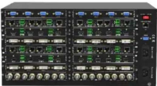
natural_image
Front view of a black network equipment rack with multiple Ethernet ports and indicator lights (no visible text or labels)All Rights Reserved
Version: ALF-MMX3232A-N 2021V3.2
Preface
Read this user manual carefully before using the product. Pictures are shown in this manual for reference only. Different models and specifications are subject to real product.
This manual is only for operation instruction, please contact the local distributor for maintenance assistance. The functions described in this version is updated as of December, 2019. In the constant effort to improve the product, we reserve the right to make functions or parameters changes without notice or obligation. Please refer to the dealers for the latest details.
FCC Statement
This equipment generates, uses, and can radiate radio frequency energy and, if not installed and used in accordance with the instructions, may cause harmful interference to radio communications. It has been tested and found to comply with the limits for a Class B digital device, pursuant to part 15 of the FCC Rules. These limits are designed to provide reasonable protection against harmful interference in a commercial installation.
Operation of this equipment in a residential area is likely to cause interference, in which case the user at their own expense will be required to take whatever measures may be necessary to correct the interference.
Any changes or modifications not expressly approved by the manufacture would void the user's authority to operate the equipment.

text_image
CE FC √ ×Do not dispose of this product with the normal household waste at the end of its life cycle. Return it to a collection point for the recycling of electrical and electronic devices. This is indicated by the symbol on the product, user manual or packaging. The materials are reusable according to their markings. By reusing, recycling or other forms of utilisation of old devices you make an important contribution to the protection of our environment. Please contact your local authorities for details about collection points.
SAFETY PRECAUTIONS
To ensure the best from the product, please read all instructions carefully before using the device. Save this manual for further reference.
- Unpack the equipment carefully and save the original box and packing material for possible future shipment.
- Follow basic safety precautions to reduce the risk of fire, electrical shock, and injury to persons.
- Do not dismantle the housing or modify the module. It may result in electrical shock or burn.
- Using supplies or parts not meeting the products' specifications may cause damage, deterioration, or malfunction.
• Refer all servicing to qualified service personnel.
- To prevent fire or shock hazard, do not expose the unit to rain, moisture or install this product near liquid.
- Do not put any heavy items on the extension cable in case of extrusion.
- Do not remove the housing of the device as opening or removing housing may expose you to dangerous voltage or other hazards.
- Install the device in a place with fine ventilation to avoid damage caused by overheat.
- Keep the module away from liquids.
- Spillage into the housing may result in fire, electrical shock, or equipment damage. If an object or liquid falls or spills on to the housing, unplug the module immediately.
- Do not twist or forcefully pull the ends of the optical cable. It can cause malfunction.
- Do not use liquid or aerosol cleaners to clean this unit. Always unplug the power to the device before cleaning.
- Unplug the power cord when left unused for a long period of time.
- Information on disposal for scrapped devices: do not burn or mix with general household waste, please treat them as normal electrical wastes.
Table of Contents
1. Product Introduction....3
1.1. Features .... 3
1.2. Signal Card....4
1.3. Package List....5
2. Panel Description....5
2.1.Matrix Front Panel 6
2.2. Matrix Rear Panel....7
2.3. Signal Card....8
2.3.1.4I-VA....8
2.3.2. 4I-UH & 4O-UH....10
2.3.3. 4I-UHS & 4O-UHS....11
2.3.4. 4I-BT & 4O-BT....12
3. System Connection....14
3.1. Usage Precaution....14
3.2. Connection Diagram....14
4. Button Control....15
5. IR Remote Control....16
6. RS232 Control 17
6.1.RS232 Communication Port 17
6.2.RS232 Control Software 17
6.3.RS232 Communication Command 19
6.3.1. System Control Command....20
6.3.2. Signal Switching Command....20
6.3.3. Preset Command....21
6.3.4. EDID Management Command....21
6.3.5. 4I-VA Input Card Command....22
6.3.6. 4I-UH Input Card Command....23
6.3.7. 4I-UHS Input Card Command....23
6.3.8. 4O-UHS Output Card Command....24
6.3.9. 4I-BT Input Card Command....25
- TCP/IP Control (Optional) 27
7.1. Control Mode....27
7.2. TCP/IP Communication Software 29
7.3. TCP/IP Configuration....30
- Specification ....31
8.1.Main Unit 31
8.2. Signal Card....31
8.2.1.4I-VA....31
8.2.2. 4I-UH & 4O-UH....32
8.2.3. 4I-UHS & 4O-UHS....32
8.2.4. 4I-BT & 4O-BT 33
-
Troubleshooting & Maintenance ....35
-
After-Sales Service ...... 37
-
Warranty ....38
1. Product Introduction
The Alfatron ALF-MMX3232 is a high-performance video and audio modular matrix switcher supporting a maximum of 32 input sources and 32 output displays synchronously. It supports different video signals with cross switching. Every video or audio signal is transmitted and switched independently to decrease signal attenuation. The ALF-MMX3232 matrix supports various changeable cards including HMDI, VGA, and HDBaseT. Users can choose to insert different signal cards for different applications.
The matrix has a power failure memory function and audio can break away from or follow the video switching. The matrix has an RS232 port for serial control and an optional IP port for TCP/IP control, which can be easily controlled via third-party devices.
With its flexible design, the ALF-MMX3232 matrix can be used for an array of different projects and tend to be an all-in-one solution. It is the combination solution for multimedia conference rooms, control rooms, broadcasting rooms, shopping center, etc. It will handle all the audiovisual management, including the switching, driving, scaling, etc.
1.1. Features
- Modular chassis with configurable I/O slots, ranging from 4x4 to 32x32.
- Various I/O cards, includes HDMI, HDBaseT, and VGA cards (Compatible with YUV, YC & CVBC.) to configure any matrix.
- Truly cross-point switching, any input to any output, regardless signal format.
• Supports HDMI1.4 and 1080P 3D. - Integrated HDBaseT technology.
- Controllable via front panel buttons, RS232, and optional TCP/IP, also compatible with third party control.
- HDCP compliant.
- LCD display.
1.2. Signal Card
The matrix supports multiple signal cards as listed in the following charts:
| Signal | Model | Description |
| VGA 4I-VA | 1080P seamless VGA input card with 4 VGA and 4 external L+R audio ports. | |
| HDMI | 4I-UH | 4K HDMI input card with 4 HDMI, and 4 external L+R audio ports. |
| 4O-UH | 4K HDMI output card with 4 HDMI and 4 external L+R audio ports. | |
| 4I-UHS | 4K seamless HDMI input card with 4 HDMI and 4 external stereo audio ports. | |
| 4O-UHS | 4K seamless HDMI output card with 4 HDMI and 4 external stereo audio ports. | |
| HDBaseT | 4I-BT | 4K HDBaseT input card with 4 HDBT, 4 RS232 and 4 external stereo audio ports. |
| 4O-BT | 4K HDBaseT output card with 4 HDBT, 4 RS232 and 4 external stereo audio ports. |
1.3. Package List
• 1x ALF-MMX3232 Modular Matrix Switcher
- 1x IR Remote
- 1x RS232 Cable
• 4x Plastic Cushions
- 1x Power Cord
- 1 x User Manual
Note: Please contact your distributor immediately if any damage or defect in the components is found.
2. Panel Description
2.1. Matrix Front Panel

text_image
1 3 4 6 SYSTEM MONITOR INPUTS MENU 1 2 3 4 5 6 7 9 0 1 2 3 4 5 6 7 9 0 OUTPUTS AV 1 Undo Close All P-FF ← 2 5| No. | Name | Description |
| 1 | IR | Built-in IR sensor to receive IR signal sent from IR remote. |
| 2 | Power LED | The LED illuminates red when power is applied. |
| 3 | LCD Screen | Shows real-time operation status. |
| 4 | INPUTS | Back-lit buttons for input selection, ranges from 0 ~ 9, 32 selectable channels in total. |
| 5 | OUTPUTS | Back-lit buttons for output selection, ranges from 0 ~ 9, 32 selectable channels in total. |
| 6 | MENU | AV: Switch video and audio signal synchronously. |
| ,: Division button, to divide the output channels when switching to more than one channel. | ||
| ENTER: Confirm switching operation. Switching will not be executed by the matrix without confirmation. | ||
| ALL: To transfer an input channel to all output channels. | ||
| THROUGH: To transfer the signals directly to the corresponding output channels. | ||
| UNDO: Undo button, to resume to the status before the command just performed. | ||
| ←: Backspace button, to backspace the last button pressed. |
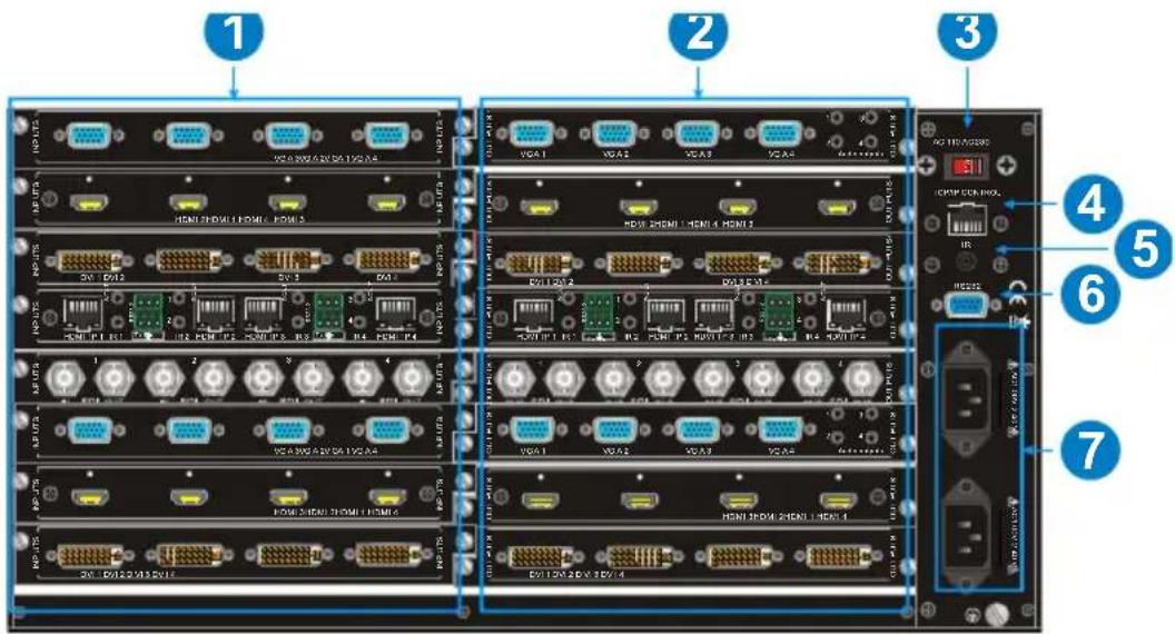
2.2. Matrix Rear Panel
text_image
1 2 3 4 5 6 7 HDMI 2000.6.2V/SA 1VGA-1A HDMI 2000.6.2V/SA 1VGA-1B HDMI 2000.6.2V/SA 1VGA-1C HDMI 2000.6.2V/SA 1VGA-1D HDMI 2000.6.2V/SA 1VGA-1E HDMI 2000.6.2V/SA 1VGA-1F HDMI 2000.6.2V/SA 1VGA-1G HDMI 2000.6.2V/SA 1VGA-1H HDMI 2000.6.2V/SA 1VGA-1I HDMI 2000.6.2V/SA 1VGA-1J HDMI 2000.6.2V/SA 1VGA-1K HDMI 2000.6.2V/SA 1VGA-1L HDMI 2000.6.2V/SA 1VGA-1M HDMI 2000.6.2V/SA 1VGA-1N HDMI 2000.6.2V/SA 1VGA-1O HDMI 2000.6.2V/SA 1VGA-1P HDMI 2000.6.2V/SA 1VGA-1Q HDMI 2000.6.2V/SA 1VGA-1R HDMI 2000.6.2V/SA 1VGA-1S HDMI 2000.6.2V/SA 1VGA-1T HDMI 2000.6.2V/SA 1VGA-1U HDMI 2000.6.2V/SA 1VGA-1V HDMI 2000.6.2V/SA 1VGA-1W HDMI 2000.6.2V/SA 1VGA-1X HDMI 2000.6.2V/SA 1VGA-1Y HDMI 2000.6.2V/SA 1VGA-1Z HDMI 2000.6.2V/SA 1VGA-1A HDMI 2000.6.2V/SA 1VGA-1B HDMI 2000.6.2V/SA 1VGA-1C HDMI 2000.6.2V/SA 1VGA-1D HDMI 2000.6.3V/SA 1VGA-1E HDMI 2000.6.3V/SA 1VGA-1F HDMI 2000.6.3V/SA 1VGA-1G HDMI 2000.6.3V/SA 1VGA-1H HDMI 2000.6.3V/SA 1VGA-1I HDMI 2000.6.3V/SA 1VGA-1J HDMI 2000.6.3V/SA 1VGA-1K HDMI 2000.6.3V/SA 1VGA-1L HDMI 2000.6.3V/SA 1VGA-1M HDMI 2000.6.3V/SA 1VGA-1N HDMI 2000.6.3V/SA 1VGA-1O HDMI 2000.6.3V/SA 1VGA-1P HDMI 2000.6.3V/SA 1VGA-1Q HDMI 2000.6.3V/SA 1VGA-1R HDMI 2000.6.3V/SA 1VGA-1S HDMI 2000.6.3V/SA 1VGA-1T HDMI 2000.6.3V/SA 1VGA-1U HDMI 2000.6.3V/SA 1VGA-1U| No. | Name | Description |
| 1 | INPUTS | Signal card slots to insert required input cards. |
| 2 | OUTPUTS | Signal card slots to insert required output cards. |
| 3 | Power Switch | Switch between AC110V and AC230V to access different power. |
| 4 | TCP/IP | (Optional) Used for TCP/IP control port. |
| 5 | IR | IR input to connect IR receiver. |
| 6 | RS232 | Serial control port, connect with RS232 port of control device. |
| 7 | Power Ports | Connect with household alternating current power, including one redundant power. |
Note: There are only eight input and eight output slots for the matrix, which enables only eight input cards and eight output cards to be installed. The input / output cards can be changed based on your requirements and supports hot plug and play.
2.3. Signal Card
The ALF-MMX3232 matrix supports expansion through various changeable input / output cards of different signals including HDMI, VGA, and HDBaseT.
Below is a brief introduction to the changeable cards.
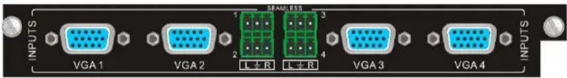
2.3.1. 4I-VA
1080P seamless VGA input card with 4 VGA and 4 external L+R audio ports.
text_image
INPUTS VGA 1 VGA 2 1 L ± R 2 BEAMLESS L ± R 3 4 VGA 3 VGA 4 INPUTS4I-VA
- Supports seamless switching, it can be used in combination with other seamless output signal card.
• Supports video upscaling, converting input video to 1080P or 1920x1200P.
• Supports input resolution selection. - Manually select VGA (RGBHV), YPbPr, S-VIDEO or C-VIDEO signal format.
- Compatible with HDMI and DVI signal input.
• Supports YCBCR or RGB chrominance space.
• Supports VGA input signal auto correction.
• Supports 4 external L+R audio inputs and audio channel control.
Pin layout of female VGA connector:

text_image
5 4 3 2 1 10 9 8 7 6 15 14 15 12 11| Pin | Signal | Pin | Signal |
| 1 | RED | 9 | KEY/PWR |
| 2 | GREEN | 10 | GND |
| 3 | BLUE | 11 | ID0/RES |
| 4 | ID2/RES | 12 | ID1/SDA |
| 5 | GND | 13 | HSync |
| 6 | RED_RTN | 14 | VSync |
| 7 | GREEN_RTN | 15 | ID3/SCL |
| 8 | BLUE_RTN |
When connecting to YPbPr or C-VIDEO signal, insert converting cables according to specific pin definitions (see the figures below):
VGA- YPbPr:
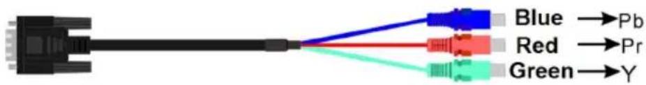
text_image
Blue →Pb Red →Pr Green →Y| Pin | Signal | Pin | Signal |
| 1 | RED | 6 | GND |
| 2 | GREEN | 7 | GND |
| 3 | BLUE | 8 | GND |
| Other pins are not used. | |||
VGA-C-VIDEO:

text_image
Blue Red → C-VIDEO Green| Pin | Signal | Pin | Signal |
| 1 | RED | 6 | GND |
| 7 | GND | 8 | GND |
| Other pins are not used. | |||
2.3.2. 4I-UH & 4O-UH
4K HDMI input card with 4 HDMI, and 4 external L+R audio ports.
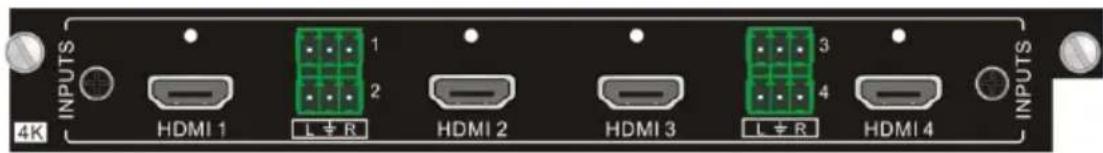
text_image
4K INPUTS HDMI 1 L ± R 1 2 HDMI 2 HDMI 3 L ± R 3 4 HDMI 4 INPUTS4I-UH
• Supports HDMI 1.4 and HDCP 1.4.
- Compatible with DVI signal.
- Input resolution is up to 4Kx2K and supports 1080P 3D.
• Synchronously switch audio and video.
• Supports 4 external L+R audio inputs and audio channel control.
4K HDMI output card with 4 HDMI, and 4 external L+R audio ports.
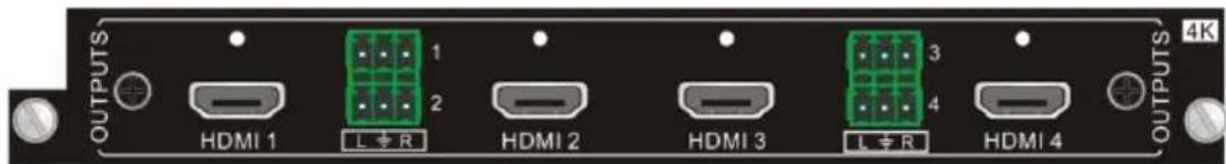
text_image
OUTPUTS HDMI 1 L ≠ R HDMI 2 HDMI 3 L ≠ R HDMI 4 OUTPUTS 4K40-UH
• Supports HDMI 1.4 and HDCP 1.4.
- Compatible with DVI signal.
- Output resolution is up to 4Kx2K and supports 1080P 3D.
- Synchronously switch audio and video.
• Supports 4 external L+R audio outputs.
2.3.3. 4I-UHS & 4O-UHS
4K seamless HDMI input card with 4 HDMI and 4 external stereo audio ports.

text_image
SEAMLESS INPUTS HDMI 1 Audio 1 2 HDMI 2 Audio 3 4 HDMI 3 HDMI 4 INPUTS 4K4I-UHS
• Supports HDMI 1.4 and HDCP 2.2.
- Compatible with DVI-D signal.
• Resolution is up to 4096x2160@60Hz 4:2:2.
- Input signal card has character overlay function, and character can be changed to relative attribute via the commands.
• Supports audio embedded function.
- Input card supports OSD menu function.
4K seamless HDMI output card with 4 HDMI and 4 external stereo audio ports.
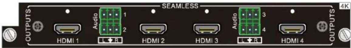
text_image
SEAMLESS OUTPUTS HDMI 1 Audio 1 2 HDMI 2 HDMI 3 Audio 3 4 L R L R HDMI 4 OUTPUTS 4K40-UHS
• Supports HDMI 1.4 and HDCP 2.2.
- Compatible with DVI-D signal.
• Resolution is up to 4096x2160@60Hz 4:2:2.
- Supports various output resolutions: 1024x768@60Hz, 1360x768@60Hz, 1280x720@60Hz, 1920x1080@30Hz, 1920x1080@60Hz, 3840x2160@30Hz, 4096x2160@30Hz.
• Supports audio de-embedded function.
- Output card supports simple view splicing function.
2.3.4. 4I-BT & 4O-BT
4K HDBaseT input card with 4 HDBT, 4 RS232 and 4 external stereo audio ports.
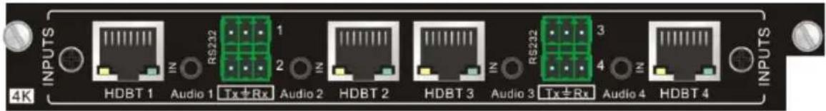
text_image
4K INPUTS HDBT 1 Audio 1 Tx ± Rx Audio 2 HDBT 2 HDBT 3 Audio 3 Tx ± Rx Audio 4 HDBT 4 RS232 1 2 3 4 INPUTS4I-BT
• Supports HDBT 1.0, HDMI 1.4 and HDCP 1.4.
- Input resolution is up to 4Kx2K and supports 1080P 3D.
- It is used with HDBaseT transmitter to extend video signal up to 70 meters for 1080P, or 40 meters for 4Kx2K.
- Features four RS232 ports for two-way RS232 pass-through.
- The RS232 baud rate supports 2400, 4800, 9600, 19200, 38400, 57600, 115200.
• Supports four external stereo audio inputs and audio channel control.
4K HDBaseT output card with 4 HDBT, 4 RS232 and 4 external stereo audio ports.

text_image
OUTPUTS HDBT 1 RS232 1 RS232 Audio 1 Tx + Rx Audio 2 HDBT 2 HDBT 3 RS232 3 4 4K Audio 3 Tx + Rx Audio 4 HDBT 4 OUTPUTS 4K40-BT
• Supports HDBT 1.0 and HDCP 1.4.
- Output resolution is up to 4Kx2K and supports 1080P 3D.
- It is used with HDBaseT receiver to extend video signal up to 70 meters for 1080P, or 40 meters for 4Kx2K.
- Features four RS232 ports for two-way RS232 pass-through.
- The RS232 baud rate supports 2400, 4800, 9600, 19200, 38400, 57600, 115200.
• Supports four external stereo audio outputs and audio channel control.
How the indicators work:
| Color | Definition | Status |
| Yellow Power LED | The LED illuminates yellow when power is applied. | |
| Green Link | LED | The LED illuminates green when the port is successfully connected to other device via CAT6 / 6a / 7 cable. |
Pin layout of the HDBT connector:
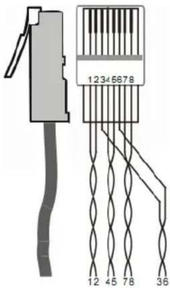
text_image
12345678 12 45 78 36| Pin | Color |
| 1 | orange white |
| 2 | orange |
| 3 | green white |
| 4 | blue |
| 5 | blue white |
| 6 | green |
| 7 | brown white |
| 8 | brown |
| 1st Group | 4--5 |
| 2nd Group | 1--2 |
| 3rd Group | 3--6 |
| 4th Group | 7--8 |
Note: Cable RJ45 connectors MUST be metal, and the shielded layer of cable MUST be connected to the connector's metal shell, to ensure sufficient grounding.
3. System Connection
3.1. Usage Precaution
- Ensure all components and accessories are included before installation.
- System should be installed in a clean environment with adequate temperature and humidity.
- All of the power switches, plugs, sockets, and power cords should be insulated and safe.
- All devices should be connected before powering on.
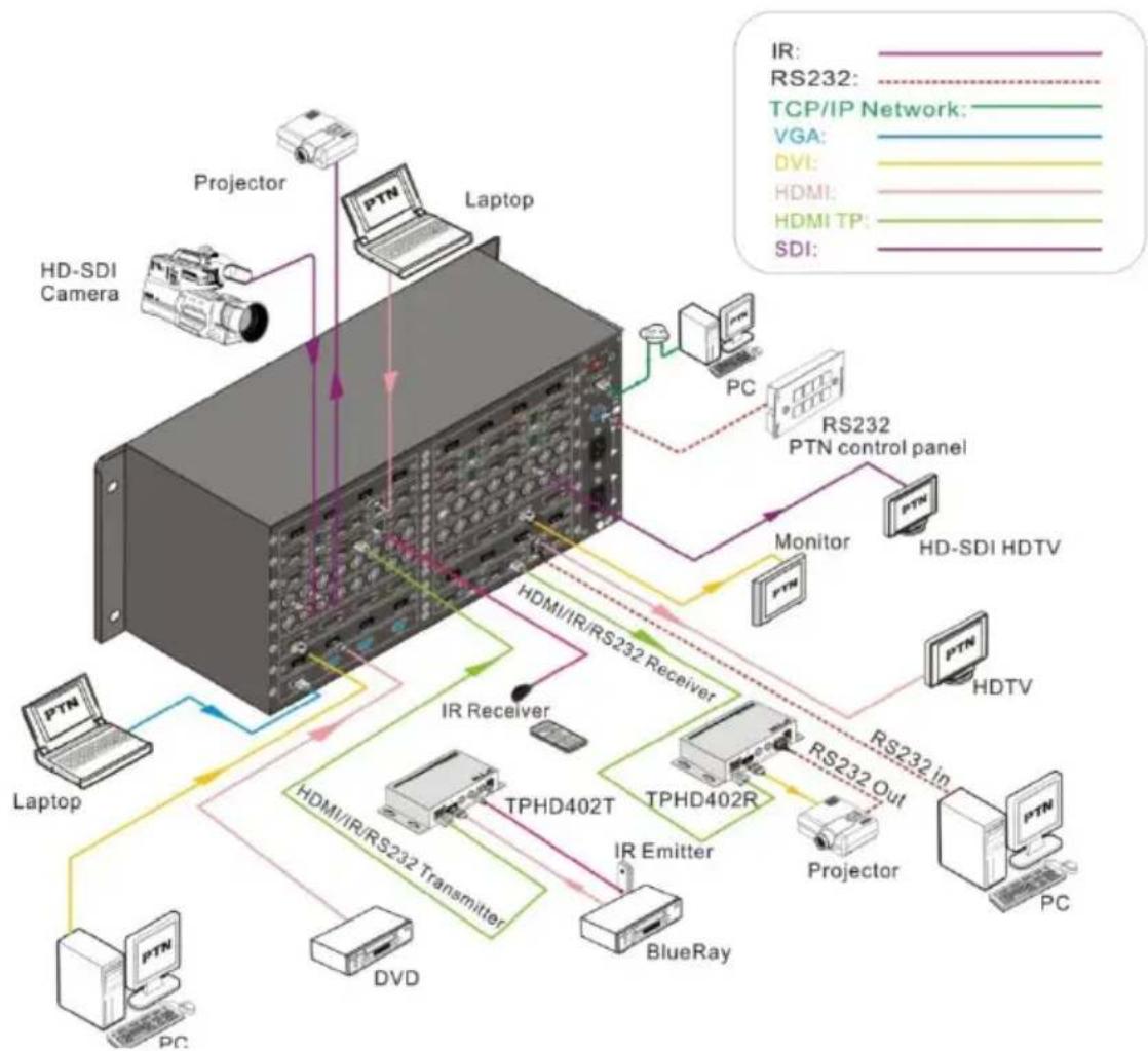
3.2. Connection Diagram
flowchart
graph TD
    A["HD-SDI Camera"] -->|IR| B["Laptop"]
    C["Projector"] -->|IR| B
    D["PTN"] -->|IR| B
    E["PC"] -->|IR| B
    F["Monitor"] -->|IR| G["HD-SDI HDTV"]
    H["PTN"] -->|IR| I["HDTV"]
    J["PTN"] -->|IR| K["PTN"]
    L["PTN"] -->|IR| M["PTN"]
    N["PTN"] -->|IR| O["PTN"]
    P["PTN"] -->|IR| Q["PTN"]
    R["PTN"] -->|IR| S["PTN"]
    T["PTN"] -->|IR| U["PTN"]
    V["PTN"] -->|IR| W["PTN"]
    X["PTN"] -->|IR| Y["PTN"]
    Z["PTN"] -->|IR| AA["PTN"]
    AB["Laptop"] --> AC["HDMI/IR/RS232 Transmitter"]
    AD["DVD"] --> AE["BlueRay"]
    AF["IR Receiver"] --> AG["TPHD402T"]
    AH["IR Emitter"] --> AI["TPHD402R"]
    AJ["MTN"] --> AK["RD1000"]
    AL["MDI"] --> AM["MDI TP"]
    AN["MDI"] --> AO["MDI TP"]
    AP["MDI"] --> AQ["MDI TP"]
    AR["MDI"] --> AS["MDI TP"]
    AT["MDI"] --> AU["MDI TP"]
    AV["MDI"] --> AW["MDI TP"]
    AX["MDI"] --> AY["MDI TP"]
    AZ["MDI"] --> BA["MDI TP"]
    BB["MDI"] --> BC["MDI TP"]
    BD["MDI"] --> BE["MDI TP"]
    BF["MDI"] --> BG["MDI TP"]
    BH["MDI"] --> BI["MDI TP"]
    BJ["MDI"] --> BK["MDI TP"]
    BL["MDI"] --> BM["MDI TP"]
    BN["MDI"] --> BO["MDI TP"]
    BP["MDI"] --> BQ["MDI TP"]
    BR["MDI"] --> BS["MDI TP"]
    BT["MDI"] --> BU["MDI TP"]
    BV["MDI"] --> BW["MDI TP"]
    BX["MDI"] --> BY["MDI TP"]
    BZ["MDI"] --> CA["MDI TP"]
    CB["MDI"] --> CC["MDI TP"]
    CD["MDI"] --> CE["MDI TP"]
    CF["MDI"] --> CG["MDI TP"]
    CH["MDI"] --> CI["MDI TP"]
    CJ["MDI"] --> CK["MDI TP"]
    CL["MDI"] --> CM["MDI TP"]
    CN["MDI"] --> CO["MDI TP"]
    CP["MDI"] --> CQ["MDI TP"]
    CR["MDI"] --> CS["MDI TP"]
    CT["MDI"] --> CU["MDI TP"]
    CV["MDI"] --> CW["MDI TP"]
Note: All the input and output signal cards don't support hot-plug, but the input and output ports on the signal cards support.
4. Button Control
The matrix can be controlled via the front panel buttons. To switch AV signal, please operate the buttons using the following order:
Order: "Input Channel" + "AV" + "Output Channel" + "Enter"
Note:
- Input Channel: Fill with the number of the input channel to be controlled.
- Output Channel: Fill with the number of output channels to be controlled. Press "All" to select all the outputs.
- Use “,” button to separate multiple I/O channels, and press “ENTER” button to confirm the operation.
- The input/output channels on the rear panel are counted from left to right, top to bottom.
- The input delay time between two numbers of every input & output channel must be less than 5 seconds; if not, the operation will be cancelled.
- Example: To transfer input 1 to output 11, press input "1", output "1" "1" and "Enter".
To transfer signals from input 1 to all output channels, press buttons in this order: "1", "All".
Other Functional Buttons:
| Buttons | Description | Operation |
| UNDO | Return to the previous status | Status 1: Input 6 -> output 6Press input “6” + “AV” + output 4 to change the connection. Press “Undo” to return to Status 1. |
| ← | Backspace the last operation | If you press buttons “1”, “AV”, “2”, “←” in order, then “2” will be canceled. |
| THROUGH | Get straight I/O connection, e.g., input 1-> output 1, input 2-> output 2. | Format: “Input Channel” + “Through”If you press buttons “ALL”, “THROUGH” in order, then the result will be like input 1→ output 1, input 2 → output 2, input 3 → output 3 ... input 16 → output 16. |
5. IR Remote Control
The ALF-MMX3232 matrix can be controlled via the remote. As the function buttons on the IR remote are the same with the ones on the front panel, the IR remote shares the same operations and commands with the control panel.
Press the buttons under below format:
"Input Channel" + "Switch Mode" + "Output Channel"

text_image
INPUTS 1 2 3 4 5 6 7 8 9 0 10+ AV VIDEO AUDIO ALL THROUGH UNDO ← 1 2 3 4 5 6 7 8 9 0 10+ OUTPUTS Professional Audio/Video Matrix Switcher
text_image
INPUTS 1 2 3 4 5 6 7 8 9 0 10+Input channel buttons, including 1\~10+
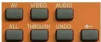
text_image
AV VIDEO AUDIO ALL THROUGH UNDOMenu buttons, buttons VIDEO and AUDIO are not available.
text_image
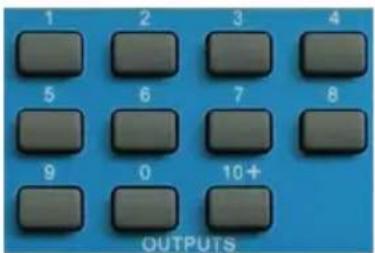
1 2 3 4 5 6 7 8 9 0 10+ OUTPUTSOutput channel buttons, including 1\~10+
6. RS232 Control
6.1. RS232 Communication Port
Apart from the front control panel and IR remote, the ALF-MMX3232 matrix can be controlled by a far-end control system or through the Ethernet control via the RS-232 communication port.
This RS-232 communication port is a female 9-D connector. The definition of its pin layout is shown in the table below:

text_image
5 1 9 6 Female| No. | Pin | Function |
| 1 | N/u | Unused |
| 2 | Tx | Transmit |
| 3 | Rx | Receive |
| 4 | N/u | Unused |
| 5 | Gnd | Ground |
| 6 | N/u | Unused |
| 7 | N/u | Unused |
| 8 | N/u | Unused |
| 9 | N/u | Unused |
6.2. RS232 Control Software
When the ALF-MMX3232 matrix connects to the RS232 port of a computer with control software, users can control it via that computer. To control the switcher, users need to use an RS232 control software.
- Installation: Copy the control software file to the computer connected to the Transmitter.
- Uninstallation: Delete all the control software files in corresponding file path.
- Basic Setting
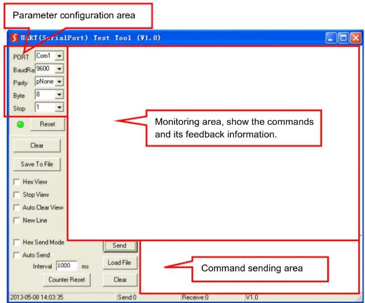
Connect the matrix to all input devices and output devices required, then connect it to a PC which has the RS232 control software installed. Double-click the software icon to run this software. Please refer the software CommWatch.exe as example. The icon is shown below:

CommWatch.exe
The interface of the control software is shown below:
text_image
Parameter configuration area UART(SerialPort) Test Tool (V1.0) PORT Com1 BaudRa 9600 Parity pNone Byte 8 Stop 1 Reset Clear Save To File Hex View Stop View Auto Clear View New Line Hex Send Mode Send Auto Send Interval 1000 ms Load File Counter Reset Clear 2013-05-08 14:03:35 Send:0 Receive:0 V1.0 Monitoring area, show the commands and its feedback information. Command sending areaPlease set the parameters of COM number, baud rate, data bit, stop bit and the parity bit correctly, only then can the RS232 commands be sent in the Command Sending Area.
6.3. RS232 Communication Command
With this command system, users are able to control and operate the ALF-MMX3232 matrix with RS232 software remotely.
Note:
- Please disconnect all the twisted pairs before sending command EDIDUpgrade[X].
- In the commands, “[” and “]” are symbols for easy reading and do not need to be typed in actual operation.
- Please remember to end the commands with the ending symbols “.” or “.”
• Type the command carefully, it is case-sensitive. - Commands pertaining to EDID is only for signal cards that support EDID management.
- The matrix boasts 6 in-built EDID data, the chart below illustrates the detailed information:
| No. | Detailed Information |
| 1 | 1080P 2D 5.1CH |
| 2 | 1080P 2D 2.0CH |
| 3 | 720P 2D 5.1CH |
| 4 | 720P 2D 2.0CH |
| 5 | 4kx2k 2D 5.1CH |
| 6 | 4kx2k 2D 2.0CH |
Update in-built EDID data by sending the command: UpgradeIntEDID[x].
Communication protocol:
Baud rate: 9600;
Data bit: 8;
Stop bit: 1;
Parity bit: none.
6.3.1. System Control Command
| Command | Description | Feedback |
| /*Type; | Get the system model. | xxxxx |
| /%Lock; | Lock front panel buttons. | System Locked! |
| /%Unlock; | Unlock front panel buttons. | System Unlock! |
| /^Version; | Get the firmware version. | Vx.x.x |
| /:MessageOff; | Disable feedback message | Closed The Message Return. |
| /:MessageOn; | Enable feedback message (Default) | Enabled The Message Return. |
| Undo. | Cancel the previous operation | Undo |
| Demo. | Switch to testing mode, switch AV 1>1, 2>2 and so on... | Demo Mode AV: 01->001 ... ... |
| PWON. | Power on the system. | PWON |
| PWOFF. | Turn the system to standby mode. | PWOFF |
| /V00. | Get the backboard software version. | Vx.x.x |
| %0911. | Restore factory default.All I/O connection will be restored to straight through: 1->1, 2->2... saved operation status will remain the same. |
6.3.2. Signal Switching Command
| Command | Description | Feedback |
| [x]All. | Switch input [x] AV to all outputs. | 01 To All |
| All#. | Switch all input signal to the corresponding output channel | All Through. |
| All. | Switch off all outputs. | All Closed. |
| [x]#. | Switch input [x] to output [x]. | 01 Through. |
| [x] . | Switch off the output [x]. | AV: 01 Closed. |
| All@ . | Switch on all outputs. | All Open. |
| [x]@ . | Switch on the output [x]. | 01 Open. |
| [x]V[y1](&[y2]....). | Switch input [x] only video to output [y1] (and all target output in [y2] and so on). | V: 01->001 |
| [x1]B[y1](&[y2]....). | Switch input [x] AV signal to output [y1] (and all target output in [y2] and so on). | AV: 01->001 |
| Status[x]. | Get the input channel on output [x]. | V: 01->001A: 01->001 |
| Status. | Get the input channel on output channelone by one. A: 01->001 | V: 01->001... ...C |
6.3.3. Preset Command
| Command | Description | Feedback |
| Save[Y]. | Store the current status to preset [Y].[Y] ranges from 1 to 9. | Save To F8 |
| Recall[Y]. | Recall preset [Y] | Recall From F8V: 01->001A: 01->001... ... |
| Clear[Y]. | Clear the preset [Y] | Clear F8 |
6.3.4. EDID Management Command
| Command | Description | Feedback |
| UpgradeIntEDI D[x]. | Upgrade built-in EDID data. When the command applied, system prompts to upload the EDID file (.bin). [x] ranges 1 – 6. | Prompt to upload EDID file......Upload EDID to system completed |
| EDIDUpgrade[x]. | Upgrade the EDID data of the input port [x]. When the command applied, system prompts to upload the EDID file (.bin). Operation will be cancelled in 10 seconds. | Prompt to upload EDID file......Upload EDID to input card completed |
| EDID/[x]/[y]. | Set the built-in EDID data type [y] to input port [x]. [y]= 1~6. | Set system EDID[y] to input [x] |
| EDIDG[x]. | Get the EDID data from output port [x] and display on serial port. | |
| EDIDMInit. | Reset all input card EDID to all input card | EDIDMInit |
| EDIDM[x]B[y]. | Set the EDID data of output [x] on input [y]. | EDIDM2B1 |
6.3.5. 4I-VA Input Card Command
| Command | Description | Feedback |
| USER/I/[x]:0622%; | Set the input [x] to VGA signal. | 0622% |
| USER/I/[x]:0623%; | Set the input [x] to YPbPr signal. | 0623% |
| USER/I/[x]:0624%; | Set the input [x] to S-VIDEO signal. | 0624% |
| USER/I/[x]:0625%; | Set the input [x] to C-VIDEO signal. | 0625% |
| USER/I/[x]:0648%; | Switch on audio of input [x]. | 0648% |
| USER/I/[x]:0649%; | Switch off audio of input [x]. | 0649% |
| USER/I/[x]:0684%; | Set the color space of of input [x] to YCBCR. | 0684% |
| USER/I/[x]:0685%; | Set the color space of of input [x] to RGB. | 0685% |
| USER/I/[x]:0686%; | Set the signal format of input [x] to HDMI. | 0686% |
| USER/I/[x]:0687%; | Set the signal format of input [x] to DVI. | 0687% |
| USER/I/[x]:0626%; | Set the resolution of input [x] to 1024x768p@60Hz. | 0626% |
| USER/I/[x]:0627%; | Set the resolution of input [x] to 1280x720P@60Hz. | 0627% |
| USER/I/[x]:0628%; | Set the resolution of input [x] to 1280x800P@60Hz. | 0628% |
| USER/I/[x]:0619%; | Set the resolution of input [x] to 1360x768p@60Hz. | 0619% |
| USER/I/[x]:0621%; | Set the resolution of input [x] to 1600x1200P@60Hz. | 0621% |
| USER/I/[x]:0629%; | Set the resolution of input [x] to 1920x1080P@60Hz. | 0629% |
| USER/I/[x]:0620%; | Set the resolution of input [x] to 1920x1200P@60Hz. | 0620% |
| USER/I/[x]:0617%; | Restore the input [x] signal card to factory default. | 0617% |
| USER/I/[x]:0606%; | Automatically calibrate the VGA signal of input [x]. | 0606% |
| USER/I/[x]:0698%; | Upgrade the software of input [x]. | 0698% |
6.3.6. 4I-UH Input Card Command
| Command | Description | Feedback |
| AUDIO[x]l[z]. | Select audio source for input [x][x] is port number; [z] stands for audio source, it can be 0 (embedded HDMI audio) or 1 (analog audio) | AUDIO1I0. |
6.3.7. 4I-UHS Input Card Command
| Command | Description | Feedback |
| AUDIO[x]l[z]. | Select audio source for input [x][x] is port number; [z] stands for audio source, it can be 0 (embedded HDMI audio) or 1 (analog audio) | AUDIO110. |
| USER/I/[x]:<<*******>>%; | Add the characters <<*******>, [x] is for port number. Up to 10 characters. | < |
| USER/I/[x]:0900%; | Disable character overlay function. | 0900% |
| USER/I/[x]:0901%; | Enable character overlay function. | 0901% |
| USER/I/[x]:0902%; | Show characters in the top left corner. | 0902% |
| USER/I/[x]:0903%; | Show characters in the top right corner. | 0903% |
| USER/I/[x]:0904%; | Show characters in the bottom-left corner. | 0904% |
| USER/I/[x]:0905%; | Show characters in the bottom-right corner. | 0905% |
| USER/I/x:0906%; | Set the color of characters to white. | 0906% |
| USER/I/x:0907%; | Set the color of characters to red. | 0907% |
| USER/I/x:0908%; | Set the color of characters to green. | 0908% |
| USER/I/x:0909%; | Set the color of characters to blue. | 0909% |
| USER/I/x:0911%; | Set the character font to small. | 0911% |
| USER/I/x:0912%; | Set the character font to large. | 0912% |
| USER/I/x:0617%; | Restore the output [x] signal card to factory default. | 0617% |
| USER/I/[x]:02xx%; | Set the image brightness of input [x] to xx, xx=00~99. | 02xx% |
| USER/I/[x]:03xx%; | Set the image contrast of input [x] toxx, xx=00~99. | 03xx% |
| USER/I/[x]:04xx%; | Set the image saturation of input [x] to xx, xx=00~99. | 04xx% |
| USER/I/[x]:05xx%; | Set the image sharpness of input [x] to xx, xx=00~99. | 05xx% |
| USER/I/[x]:0607%; | Set the image color temperature of input [x] to user/cool/medium/warm. | 0607% |
| USER/I/[x]:0608%; | Set the image aspect ratio of input [x] to 16:9/4:3/Auto/Panorama/Just scan/Zoom2/Zoom1. | 0608% |
| USER/I/[x]:0614%; | Set the image mode of input [x] to user/Dynamic/Standard/mild. | 0614% |
| USER/I/[x]:0698% | Upgrade the software of input [x]. | 0698% |
6.3.8. 4O-UHS Output Card Command
| Command | Description | Feedback |
| USER/O/[x]:0804%; | Set the resolution of output [x] to 1280x720P@60Hz. | ResolutionOut02 1280x720 P |
| USER/O/[x]:0813%; | Set the resolution of output [x] to1920x1080P@60Hz. | ResolutionOut02 1920x1080P |
| USER/O/[x]:0824%; | Set the resolution of output [x] to 1024x768p@60Hz. | ResolutionOut02 1024*768 60HZ |
| USER/O/x:0828%; | Set the resolution of output [x] to 1360x768p@60Hz. | ResolutionOut02 1360*768 60HZ |
| USER/O/[x]:0840%; | Set the resolution of output [x] to 3840x2160@30Hz. | ResolutionOut02 4K*2K 30HZ |
| USER/O/[x]:0841%; | Set the resolution of output [x] to 3840x2160@60Hz | ResolutionOut02 4K*2K 60HZ |
| USER/O/[x]:0844%; | Set the resolution of output [x] to 4096x2160@30Hz. | ResolutionOut02 4K*2K30HZ |
| USER/O/[x]:0845%; | Set the resolution of output [x] to 4096x2160@60Hz. | ResolutionOut02 4K*2K 60HZ |
| GetResolution[x]. | Get the resolution of output [x]. | ResolutionOu001 3840x216030Hz |
| USER/O/x:0617%; | Restore the output [x] signal card to factory default. | 0617% |
| USER/O/[x]:24XX%; | The horizon direction of the output [x] signal is divided into XX blocks. The value of XX should be less than 9. | 24xx% |
| USER/O/[x]:25XX%; | The vertical direction of the output [x] signal is divided into XX blocks. The value of XX should be less than 9. | 25xx% |
| USER/O/[x]:26XX%; | Set the horizon direction of the output [x] signal to show block XX. | 26xx% |
| USER/O/[x]:27XX%; | Set the vertical direction of the output [x] signal to show block XX. | 27xx% |
| USER/O/[x]:0110%; | Enable the analog audio output [x]. | 0110% |
| USER/O/[x]:0111%; | Disable the analog audio output [x]. | 0111% |
| USER/O/[x]:0103%; | Set the signal format of output [x] to HDMI. The command is invalid when the output resolution is 4K@60Hz. | 0103% |
| USER/O/[x]:0104%; | Set the signal format of output [x] to DVI. The command is invalid when the output resolution is 4K@60Hz. | 0104% |
6.3.9. 4I-BT Input Card Command
| Command | Description | Feedback |
| AUDIO[x]l[z]. | Select audio source for input [x][x] is port number; [z] stands for audio source, it can be 0 (embedded HDMI audio) or 1 (analog audio) | AUDIO1I0. |
Examples:
- Switch signal from an input channel to all output channels: [x]All.
Example: Send "3All." to transfer signal from input 3 to all the output channels. - Switch all input signals to corresponding output channels respectively: All#.
Example: If this command is carried out, the status of matrix will be: 1->1, 2->2, 3->3, 4->4..... 8->8.... - Switch off all the output channels: All\$.
Example: After executing this command, there will be no signal on any of the outputs. - Switch off the detailed feedback command from the COM port: /::MessageOff; It will leave the "switch OK" as the feedback when you switch the matrix.
- Switch on the detailed feedback command from the COM port:/:MessageOn; It will show the detailed switching information when it is switched. Example: when switch 1->2, it will feedback "AV01 to 02".
- Switch signal from an input channel to corresponding output channel: [x]#.
Example: "5#." to transfer signals from input 5 to output 5. - Switch off an output channel: [x]\$
Example: "5\$." to switch off the output 5. - Switch signal: [x1] B[x2].
Example: “12B12,13,15.” to transfer signal from the input 12 to the output No. 12, 13, 15. - Inquire which input channel is routed to the output channel [x]: Status[x].
Example: Send "Status3." to inquire which input channel is routed to output 3. - Inquire which input channel is routed to which output channels individually:
Example: "Status." to inquire which input channel is routed to which output channels individually. - Save the present operation to the preset command [Y]: Save[Y].
Example: "Save7." to save the present operation to the preset command No.7. - Recall the preset command [Y]: Recall[Y].
Example: "Recall5." to recall the preset command No.5. - Clear the preset command [Y]: Clear[Y].
Example: "Clear5." to clear the preset command No.5. - EDID management command: EDIDM[X]B[Y].
Example: "EDIDM5B3." to enable input 3 to learn the EDID data of output 5.
Status.
15. Command for signal cards: USER/[Y]/[X]\*\*\*\*\*
Example: "USER/I/7:0623%;" to set the input 7 to support YPbPr signal, the card is plugged in the second input slot of the matrix.
7. TCP/IP Control (Optional)
7.1. Control Mode
TCP/IP default settings:
IP: 192.168.0.178
Gateway is 192.168.0.1
Serial Port: 4001
IP and Gateway can be changed as you require, Serial Port cannot be changed.
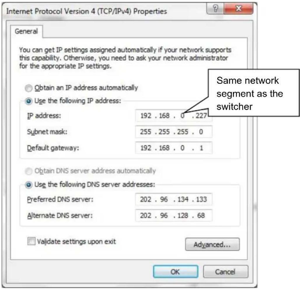
• Controlled by Single PC
Connect a computer to the TCP/IP port of the matrix and set its network segment to the same as the default IP of the matrix (192.168.0.178).
text_image
Internet Protocol Version 4 (TCP/IPv4) Properties General You can get IP settings assigned automatically if your network supports this capability. Otherwise, you need to ask your network administrator for the appropriate IP settings. Obtain an IP address automatically Use the following IP address: IP address: 192 . 168 . 0 . 227 Subnet mask: 255 . 255 . 255 . 0 Default gateway: 192 . 168 . 0 . 1 Obtain DNS server address automatically Use the following DNS server addresses: Preferred DNS server: 202 . 96 . 134 . 133 Alternate DNS server: 202 . 96 . 128 . 68 Validate settings upon exit Advanced... OK Cancel Same network segment as the switcher• Controlled by PC(s) in LAN
The matrix can be connected to a router to make up a LAN with the PC(s); this ensures it is able to be controlled in a LAN. When controlling, ensure the matrix's network segment is the same with the router. Connection diagram for LAN control below:

flowchart
graph TD
    A["TCP/IP"] -->|TCP/IP| B["Router"]
    B --> C["PC"]
    B -->|CAT5e| C
    B --> D["Internet"]
Step1. Connect the TCP/IP port of the matrix to the Ethernet port of the PC with a twisted pair CAT cable.
Step2. Set the PC's network segment to the same as the matrix. Do please remember the PC's original network segment.
Step3. Set the matrix's network segment to the same as the router.
Step4. Set the PC's network segment to the original one.
Step5. Connect the matrix and PC(s) to the router. In the same LAN, each PC is able to control the matrix synchronously.
The PC(s) are now able to control the device via a TCP/IP communication software.
7.2. TCP/IP Communication Software
(Exampled by TCPUDP software)
1) Connect a computer and the matrix to the same network. Open the TCPUDP software (or any other TCP/IP communication software) and create a connection, enter the IP address and port of the matrix (default IP: 192.168.0.178, port:4001):

text_image
Operate(O) View(V) Windows(W) Help(H) Language CreateConn CreateServer StartServer Connect DisconnectAll DeleteConn Properties 4 X Client Mode Server Mode Create Connection Type: ICP DustIP: 102.368.0.178 Port: 4001 LocalPort Auto Specis 4001 AutoConn: Eve 0 x Send View Type Eve ns Create Cancel2) After successful connection, the commands can be entered to control the matrix, as below:

text_image
192.168.0.178:4001 Send AtuoSend Eve 100 ms Send Stop Send Max Send File Sand Received Clear Option BroadOption 0701% Enter your command here. Commands are the same with RS232 commands listed in 6.3 RS232 Communication Commands Ree StopShow Clear Save Option ShowHex Save (In Time) Count Send 0 Recv 0 Clear Here you will receive the feedback when a command is sent.7.3. TCP/IP Configuration
Type the designed website 192.168.0.178:100 into your browser. Enter the correct username and password to log in the WebServer:
Username: admin
Password: admin
Here is the main configuration interface of the WebServer:

text_image
goahead WEBSERVER™ m) i) m) o) bility open all | close all Select Language English Apply web-server Internet Settings Administration Status Statistic ManagementIn this interface, you can:
- Change website display language.
- Modify network settings: Go to Internet Settings -> WAN.
- Upgrade TCP/IP module: Go to Administration -> Upload Program -> Select program file -> Start upgrading.
- Reboot the device after upgrading.
8. Specification
8.1. Main Unit
| Control parts | |
| Serial Control Port | RS-232, 9- female D connector |
| Configuration | 2 = TX, 3 = RX, 5 = GND |
| Installation | Rack Mountable |
| Front Panel Control | Buttons |
| Option | TCP/IP control |
| General | |
| Power Supply | 100VAC ~ 240VAC, 50/60Hz |
| Power Consumption | 60W (Max, no load) |
| Operation Temperature | -10°C ~ +55°C |
| Storage Temperature | -25°C ~ +70°C |
| Relative Humility | 10% - 90% |
| Dimension (W*H*D) | 483mm x 222mm x 320mm (5U high) |
| Net Weight | About 7.5KG |
8.2. Signal Card
8.2.1. 4I-VA
| Video | |
| Input | (4) VGA |
| Input Connector | (4) Female 15-pin HD VGA |
| Input Level | 0.5 ~ 2.0Vp-p |
| Input Impedance | 75Ω |
| Audio | |
| Input | (4) Audio |
| Input Connector | (4) 3-pin pluggable terminal block |
| CMRR | 20Hz ~ 20KHz |
| Input Impedance | >10KΩ |
| General | |
| Gain | 0 dB |
| Bandwidth | YPbPr:170MHz; C-video:150MHz; VGA:170MHz |
| Video Signal Format | VGA (RGBHV), YPbPr, S-video, C-video |
| Audio Signal Format | PCM |
| Resolution | Up to 1080P@60Hz |
| Crosstalk | <-50dB@5MHz |
8.2.2. 4I-UH & 4O-UH
| 4I-UH | |
| Input | (4) HDMI, (4) Audio |
| Input Connector | (4) Female 19-pin type-A HDMI,(4) 3-pin pluggable terminal block |
| Input Level | T.M.D.S. 2.9V~3.3V |
| Input Impedance | 75Ω |
| Frequency Response | 20Hz~20K Hz |
| 4O-UH | |
| Output | (4) HDMI, (4) Audio |
| Output Connector | (4) Female 19-pin type-A HDMI,(4) 3-pin pluggable terminal block |
| Output Level | T.M.D.S. 2.9V~3.3V |
| Output Impedance | 75Ω |
| Frequency Response | 20Hz~20K Hz |
| General | |
| Gain | 0dB |
| Resolution | Up to 4Kx2K |
| Transmission Distance | 1080P≤70m, 4Kx2K ≤ 40m |
| SNR | >70dB@ 100MHz-100M |
| Return Loss | <-30dB@ 5KHz |
| Audio Signal Format | Embedded HDMI audio: PCM, Dobly Digital, DTS, DTS-HDAnalog audio: PCM |
| Standard | HDMI 1.4 and HDCP 1.4 |
| EDID | Support manual EDID management |
8.2.3. 4I-UHS & 4O-UHS
| 4I-UHS | |
| Input | (4) HDMI, (4) Analog audio |
| Input Connector | (4) Female 19-pin type-A HDMI,(4) 3-pin pluggable terminal block |
| Power Consumption | 6W |
| Color Depth | 8bit |
| 4O-UHS | |
| Output | (4) HDMI, (4) Analog audio |
| Output Connector | (4) Female 19-pin type-A HDMI,(4) 3-pin pluggable terminal block |
| Power Consumption | 6W |
| Color Depth | 8bit |
| General | |
| Signal Type | HDMI, DVI-D |
| Bandwidth | 10.2Gbps |
| Operation Temperature | 0°C~ +50°C |
| Relative Humidity | 10%~ 90% |
| Audio Format | Embedded audio supports: PCM, Dolby Digital, DTS, DTS-HD format, external audio supports PCM format. |
| EDID Management | Supports EDID following function. |
8.2.4. 4I-BT & 4O-BT
| 4I-BT | |
| Input | (4) HDBT, (4) Audio, (4) RS232 |
| Input Connector | (4) Female RJ45 (with dual-color indicator), (4) 3.5mm mini jack, (4) 3-pin pluggable terminal block, |
| Input Level | T.M.D.S 2.9V~3.3V |
| Input Impedance | 75Ω |
| Frequency Response | 20Hz~20K Hz |
| 4O-BT | |
| Output | (4) HDBT, (4) Audio, (4) RS232 |
| Output Connector | (4) Female RJ45 (with dual-color indicator), (4) 3.5mm mini jack, (4) 3-pin pluggable terminal block, |
| Output Level | T.M.D.S 2.9V~3.3V |
| Output Impedance | 75Ω |
| Frequency Response | 20Hz~20K Hz |
| General | |
| Protocol | TCP/IP |
| Gain | 0dB |
| Bandwidth | 10.2Gbps |
| Resolution | Up to 4Kx2K |
| Crosstalk | <-50dB@5MHz |
| Transmission Distance | 1080P≤70m, 4Kx2K ≤ 40m |
| Audio Signal Format | Embedded HDMI audio: PCM, Dolby Digital, DTS, DTS-HDAnalog audio: PCM |
| HDMI Standard | HDBT 1.0, HDMI 1.4 and HDCP 1.4 |
| EDID | Support manual EDID management |
- Troubleshooting & Maintenance
| Problems | Potential Causes | Solutions |
| Output image ghosting | Bad quality of the connecting cable | Try another high-quality cable |
| Inappropriate image setting of the display | Adjust corresponding image settings | |
| Output image with color loss or no video signal output | Failed connection | Reconnect the display and the matrix |
| No output image when switching | No signal at the input / output end | Check with oscilloscope or multimeter if there is any signal at the input/ output end. |
| Failed or loose connection | Ensure the connection is good | |
| The switcher is broken | Send to authorized dealer for repair. | |
| IR remote does not work | Battery is dead Change batteries | |
| IR remote is broken | Send to authorized dealer for repair. | |
| POWER indicator does not work or no response to any operation | Failed connection of power cord. | Ensure the power cord connection is good. |
| EDID management does not work normally | The HDMI cable is broken at the output end. | Change for another HDMI cable which is in good working condition. |
| There is a blank screen on the display when switching | The display does not support the resolution of the video source. | Switch again. |
| Manage the EDID data manually to make the resolution of the video source automatically compliant with the output resolution. | ||
| Static becomes stronger when connecting the video connectors | Inadequate grounding | Check the grounding and make sure it is connected well. |
| Cannot control the device by control device (e.g., a PC) through RS232 port | Wrong RS232 communication parameters | Type in correct RS232 communication parameters. |
| Broken RS232 port | Send to authorized dealer for inspection. | |
| Cannot control the device via front panel buttons while control is possible through RS232 port | The front panel buttons are locked | Send command 50605% to unlock the front panel buttons. |
Note: If your issue persists after following the above troubleshooting steps, seek further assistance from an authorized dealer or our technical support.
10. After-sales Service
Should you experience problems using the Alfatron ALF-MMX3232A-N, please refer to the manual and troubleshooting and maintenance section (6). Should the error persist, note that any transport costs of the equipment to the distributor are borne by the user during the warranty.
1) Product Limited Warranty: Alfatron warrants that its products will be free from defects in materials and workmanship for seven years, which starts from the first day of purchase.
Proof of purchase in the form of a bill of sale or receipted invoice which is evidence that the unit is within the warranty period must be presented to obtain warranty service.
2) What the warranty does not cover (servicing available for a fee):
- Warranty expiration.
- Factory applied serial number has been altered or removed from the product.
- Damage, deterioration, or malfunction caused by:
• Normal wear and tear.
- Use of supplies or parts not meeting product specifications.
- No certificate or invoice as the proof of warranty.
- The product model showed on the warranty card does not match with the product or if the product had been altered.
- Damage caused by force majeure.
• Servicing not authorized by Alfatron.
- Any other causes which do not relate to a product defect.
- Delivery, installation or labour charges for installation or setup of the product.
3) Technical Support: Contact our after-sales department at
www.alfatronelectronics.com
11. Warranty
1.1 This limited warranty covers defects in materials and workmanship in this product.
1.2 Should warranty service be required, proof of purchase must be presented to the Company. The serial number on the product must be clearly visible and not have been tampered with in any way whatsoever.
1.3 This limited warranty does not cover any damage, deterioration or malfunction resulting from any alteration, modification, improper or unreasonable use or maintenance, misuse, abuse, accident, neglect, exposure to excess moisture, fire, improper packing and shipping (such claims must be presented to the carrier), lightning, power surges, or other acts of nature. This limited warranty does not cover any damage, deterioration or malfunction resulting from the installation or removal of this product from any installation, any unauthorized tampering with this product, any repairs attempted by anyone unauthorized by the Company to make such repairs, or any other cause which does not relate directly to a defect in materials and/or workmanship of this product. This limited warranty does not cover equipment enclosures, cables or accessories used in conjunction with this product.
This limited warranty does not cover the cost of normal maintenance. Failure of the product due to insufficient or improper maintenance is not covered.
1.4 The Company does not warrant that the product covered hereby, including, without limitation, the technology and/or integrated circuit(s) included in the product, will not become obsolete or that such items are or will remain compatible with any other product or technology with which the product may be used.
1.5 Only the original purchaser of this product is covered under this limited warranty. This limited warranty is not transferable to subsequent purchasers or owners of this product.
1.6 Unless otherwise specified, the goods are warranted in accordance with the manufacturer's product specific warranties against any defect attributable to faulty workmanship or materials, fair wear and tear being excluded.
1.7 This limited warranty only covers the cost of faulty goods and does not include the cost of labor and travel to return the goods to the Company's premises.
1.8 In the event of any improper maintenance, repair or service being carried out by any third persons during the warranty period without the Company's written authorization, the limited warranty shall be void.
1.9 A 7 (seven) year limited warranty is given on the aforesaid product where used correctly according to the Company's instructions, and only with the use of the Company's components.
1.10 The Company will, at its sole option, provide one of the following three remedies to whatever extent it shall deem necessary to satisfy a proper claim under this limited warranty:
1.10.1 Elect to repair or facilitate the repair of any defective parts within a reasonable period of time, free of any charge for the necessary parts and labor to complete the repair and restore this product to its proper operating condition.; or
1.10.2 Replace this product with a direct replacement or with a similar product deemed by the Company to perform substantially the same function as the original product; or
1.10.3 Issue a refund of the original purchase price less depreciation to be determined based on the age of the product at the time remedy is sought under this limited warranty.
1.11 The Company is not obligated to provide the Customer with a substitute unit during the limited warranty period or at any time thereafter.
1.12 If this product is returned to the Company this product must be insured during shipment, with the insurance and shipping charges prepaid by the Customer. If this product is returned uninsured, the Customer assumes all risks of loss or damage during shipment. The Company will not be responsible for any costs related to the removal or re-installation of this product from or into any installation. The Company will not be responsible for any costs related to any setting up this product, any adjustment of user controls or any programming required for a specific installation of this product.
1.13 Please be aware that the Company's products and components have not been tested with competitor's products and therefore the Company cannot warrant products and/or components used in conjunction with competitor's products.
1.14 The appropriateness of the goods for the purpose intended is only warranted to the extent that the goods are used in accordance with the Company's installation, classification and usage instructions.
1.15 Any claim by the Customer which is based on any defect in the quality or condition of the goods or their failure to correspond with specification shall be notified in writing to the Company within 7 days of delivery or (where the defect or failure was not apparent on reasonable inspection by the Customer) within a reasonable time after discovery of the defect or failure, but, in any event, within 6 months of delivery.
1.16 If delivery is not refused, and the Customer does not notify the Company accordingly, the Customer may not reject the goods and the Company shall have no liability and the Customer shall pay the price as if the goods had been delivered in accordance with the Agreement.
1.17 THE MAXIMUM LIABILITY OF THE COMPANY UNDER THIS LIMITED WARRANTY SHALL NOT EXCEED THE ACTUAL PURCHASE PRICE PAID FOR THE PRODUCT