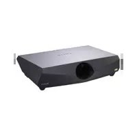
VPL-FX40L - Projector SONY - Free user manual and instructions
Find the device manual for free VPL-FX40L SONY in PDF.


| Product Type | Video Projector (3LCD) |
| Model | VPL-FX40L |
| Brand | Sony |
| Resolution | XGA (1024 x 768) |
| Brightness | 4200 ANSI Lumens |
| Contrast Ratio | 700:1 |
| Lamp Life | 2000 hours (Normal) / 3000 hours (Low) |
| Lamp Type | 265W UHP |
| Dimensions (W x H x D) | 411 x 105 x 322 mm |
| Weight | 7.5 kg |
| Power Consumption | 400W (max) |
| Power Supply | AC 100-240V, 50/60Hz |
| Input Signals | RGB/Component, S-Video, Composite, HDMI, DVI-D |
| Projection Lens | 1.3x zoom, manual focus |
| Keystone Correction | Vertical ±30°, Horizontal ±20° |
| Operating Noise | 30 dB (Low mode) |
| Warranty | 3 years (parts and labor) |
Frequently Asked Questions - VPL-FX40L SONY
User questions about VPL-FX40L SONY
0 question about this device. Answer the ones you know or ask your own.
Ask a new question about this device
Download the instructions for your Projector in PDF format for free! Find your manual VPL-FX40L - SONY and take your electronic device back in hand. On this page are published all the documents necessary for the use of your device. VPL-FX40L by SONY.
USER MANUAL VPL-FX40L SONY
Operating Instructions
HDMI TM
HIGH-DEFINITION MULTIMEDIA INTERFACE
VPL-FE40/FE40L
VPL-FX40/FX40L
VPL-FX41/FX41L
VPL-FW41/FW41L
WARNING
To reduce the risk of fire or electric shock, do not expose this apparatus to rain or moisture.
To avoid electrical shock, do not open the cabinet. Refer servicing to qualified personnel only.
WARNING
THIS APPARATUS MUST BE EARTHED.
WARNING
When installing the unit, incorporate a readily accessible disconnect device in the fixed wiring, or connect the power plug to an easily accessible socket-outlet near the unit. If a fault should occur during operation of the unit, operate the disconnect device to switch the power supply off, or disconnect the power plug.
WARNING: THIS WARNING IS APPLICABLE FOR USA ONLY.
If used in USA, use the UL LISTED power cord specified below.
DO NOT USE ANY OTHER POWER CORD.
Plug Cap Parallel blade with ground pin (NEMA 5-15P Configuration)
Cord Type SJT, three 16 or 18 AWG wires
Length Minimum 1.5 m (4 ft .11 in.), Less than 2.5 m (8 ft .3 in.)
Rating Minimum 10 A, 125 V
Using this unit at a voltage other than 120V may require the use of a different line cord or attachment plug, or both.
To reduce the risk of fire or electric shock, refer servicing to qualified service personnel.
WARNING: THIS WARNING IS APPLICABLE FOR OTHER COUNTRIES.
1 Use the approved Power Cord (3-core mains lead) / Appliance Connector / Plug with earthing-contacts that conforms to the safety regulations of each country if applicable.
2 Use the Power Cord (3-core mains lead) / Appliance Connector / Plug conforming to the proper ratings (Voltage, Ampere).
If you have questions on the use of the above Power Cord / Appliance Connector / Plug, please consult a qualified service personnel.
IMPORTANT
The nameplate is located on the bottom.
For kundene i Norge
Dette utstyret kan kobles til et IT-strømfordelingssystem.
For the customers in the USA
This equipment has been tested and found to comply with the limits for a Class A digital device, pursuant to Part 15 of the FCC Rules. These limits are designed to provide reasonable protection against harmful interference when the equipment is operated in a commercial environment. This equipment generates, uses, and can radiate radio frequency energy and, if not installed and used in accordance with the instruction manual, may cause harmful interference to radio communications. Operation of this equipment in a residential area is likely to cause harmful interference in which case the user will be required to correct the interference at his own expense.
You are cautioned that any changes or modifications not expressly approved in this manual could void your authority to operate this equipment.
All interface cables used to connect peripherals must be shielded in order to comply with the limits for a digital device pursuant to Subpart B of Part 15 of FCC Rules.
This device complies with Part 15 of the FCC Rules. Operation is subject to the following two conditions: (1) this device may not cause harmful interference, and (2)
this device must accept any interference received, including interference that may cause undesired operation.
For the State of California, USA only
Perchlorate Material - special handling may apply, See www.dtsc.ca.gov/hazardouswaste/perchlorate
Perchlorate Material: Lithium battery contains perchlorate.
For the customers in Canada
This Class A digital apparatus complies with Canadian ICES-003.
For the customers in Europe, Australia and New Zealand
WARNING
This is a Class A product. In a domestic environment, this product may cause radio interference in which case the user may be required to take adequate measures.
For the customers in Europe
The manufacturer of this product is Sony Corporation, 1-7-1 Konan, Minato-ku, Tokyo, Japan.
The Authorized Representative for EMC and product safety is Sony Deutschland GmbH, Hedelfinger Strasse 61, 70327 Stuttgart, Germany. For any service or guarantee matters please refer to the addresses given in separate service or guarantee documents.
This apparatus shall not be used in the residential area.
For safety
Be sure to attach the air filter to the unit.
For the customers in Taiwan only

廢電池請回收
Table of Contents
Precautions 5
Notes on Installation and Usage ...... 6
Unsuitable Installation 6
Usage in High Altitude .....7
Unsuitable Conditions .... 7
Overview
About the Supplied Manuals ....8
Features 8
Location and Function of Controls .. 10
Top/Front/Side 10
Rear/Side/Bottom 10
Control Panel 11
Connector Panel 12
Remote Commander 14
Projecting the Picture
Installing the Projector ...... 16
Connecting the Projector 17
Connecting a Computer 17
Connecting a VCR 19
Projecting 20
Turning Off the Power 22
Convenient Functions
Selecting the Menu Language ...... 23
Security Lock 24
Other Functions 26
Direct Power On/Off Function ... 26
Off & Go Function 26
Effective Tools for Your Presentation 26
Controlling the Computer Using a Presentation Tool, RM-PJPK1
(not supplied) (When Using the
Network Presentation
Function) 26
Adjustments and Settings Using a Menu
Using a MENU 27
The Picture Menu ......29
The Screen Menu ....31
About the Preset Memory No. .....33
The Setup Menu ....34
The Function Menu ....36
The Installation Menu ....38
The Information Menu ....40
Maintenance
Replacing the Lamp ....42
Cleaning the Air Filter ....44
Others
Troubleshooting ....45
Messages List ....48
Specifications ....49
Dimensions ....56
Index 59
Precautions
Warning
The Installation Manual contained in the CD-ROM is for dealers.
If customers perform the installation described in this manual, an accident may occur, causing serious injury. Never install it by yourself. For installation, be sure to consult with a Sony dealer.
On safety
- Check that the operating voltage of your unit is identical with the voltage of your local power supply. If voltage adaptation is required, consult with qualified Sony personnel.
- Should any liquid or solid object fall into the cabinet, unplug the unit and have it checked by qualified Sony personnel before operating it further.
- Unplug the unit from the wall outlet if it is not to be used for several days.
- To disconnect the cord, pull it out by the plug. Never pull the cord itself.
- The wall outlet should be near the unit and easily accessible.
- The unit is not disconnected from the AC power source (mains) as long as it is connected to the wall outlet, even if the unit itself has been turned off.
- Do not look into the lens while the lamp is on.
- Do not place your hand or objects near the ventilation holes — the air coming out is hot.
- Be careful not to catch your fingers by the adjuster when you adjust the height of the unit. Do not push hard on the top of the unit with the adjuster out.
- Be sure to grasp both sides of the unit with both hands when carrying the unit.
- When you set the angle of projection to more than ± 20° , read the Installation Manual for Dealers throughly for safe installation.
On illumination
- To obtain the best picture, the front of the screen should not be exposed to direct lighting or sunlight.
- Ceiling-mounted spot lighting is recommended. Use a cover over fluorescent lamps to avoid lowering the contrast ratio.
- Cover any windows that face the screen with opaque draperies.
- It is desirable to install the unit in a room where floor and walls are not of light-reflecting material. If the floor and walls are of reflecting material, it is recommended that the carpet and wall paper be changed to a dark color.
On preventing internal heat build-up
The unit is equipped with ventilation holes (intake) at the bottom and ventilation holes (exhaust) at the rear. Do not block or place anything near these holes, or internal heat build-up may occur, causing picture degradation or damage to the unit.
On cleaning
- To keep the cabinet looking new, periodically clean it with a soft cloth. Stubborn stains may be removed with a cloth lightly dampened with a mild detergent solution. Never use strong solvents, such as thinner, benzene, or abrasive cleansers, since these will damage the cabinet.
- Avoid touching the lens. To remove dust on the lens, use a soft dry cloth. Do not use a damp cloth, detergent solution, or thinner.
- Clean the filter whenever you replace the lamp.
On repacking
Save the original shipping carton and packing material; they will come in handy if you ever have to ship your unit. For maximum protection, repack your unit as it was originally packed at the factory.
On LCD projector
The LCD projector is manufactured using high-precision technology. You may, however, see tiny black points and/or bright points (red, blue, or green) that continuously appear on the LCD projector. This is a normal result of the manufacturing process and does not indicate a malfunction. Also, when you use multiple LCD projectors to project onto a screen, even if they are of the same model, the color reproduction among projectors may vary, since color balance may be set differently from one projector to the next.
Notes on Installation and Usage
Unsuitable Installation
Do not install the unit in the following situations. These installations may cause malfunction or damage to the unit.
Poorly ventilated

- Allow adequate air circulation to prevent internal heat build-up. Do not place the unit on surfaces (rugs, blankets, etc.) or near materials (curtains, draperies) that may block the ventilation holes.
- When the internal heat builds up due to the block-up, the temperature sensor will function with the message “High temp.! Lamp off in 1 min.” The power will be turned off automatically after one minute.
- Leave space of more than 30 cm (11 7 /8 inches) around the unit.
- Be careful that the ventilation holes may inhale tininess such as a piece of paper.
Highly heated and humid

- Avoid installing the unit in a location where the temperature or humidity is very high, or temperature is very low.
- To avoid moisture condensation, do not install the unit in a location where the temperature may rise rapidly.
Subject to direct cool or warm air from an air-conditioner

Installing in such a location may cause malfunction of the unit due to moisture condensation or rise in temperature.
Near a heat or smoke sensor

Malfunction of the sensor may be caused.
Very dusty, extremely smoky
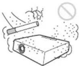
Avoid installing the unit in a very dusty or extremely smoky environment. Otherwise, the air filter will become obstructed, and this may cause a malfunction of the unit or damage it. Dust preventing the air passing through the filter may cause a rise in the internal temperature of the unit. Clean the air filter whenever you replace the lamp.
Usage in High Altitude
When using the unit at an altitude of 1,500 m or higher, set the “High Altitude Mode” to “On” in the Setup menu. Failing to set this mode when using the unit at high altitudes could have adverse effects, such as reducing the reliability of certain components.
Note on the screen
When using a screen with an uneven surface, stripes pattern may rarely appear on the screen depending on the distance between the screen and the unit or the zooming
magnifications. This is not a malfunction of the unit.
Unsuitable Conditions
Do not use the unit under the following conditions.
Do not topple the unit

Avoid using as the unit topples over on its side. It may cause malfunction.
Do not tilt right/left

Avoid using as the unit tilts more than 20 degrees. Do not install the unit other than on the floor or ceiling. These installations may cause malfunction.
Do not block the ventilation holes
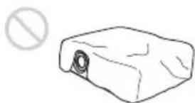
Avoid using something to cover over the ventilation holes (exhaust/intake); otherwise, the internal heat may build up.
Do not place a blocking object just in front of the lens
Do not place any object just in front of the lens that may block the light during projection. Heat from the light may damage the object. Use the PIC MUTING key on the Remote Commander to cut off the picture.
About the Supplied Manuals
The following manuals and softwares are supplied with the projector. On Macintosh system, you can read only the Operating Instructions and Installation Manual for Dealers.
Manuals
Safety Regulations (separately printed manual)
This manual describes important notes and cautions to which you have to pay attention when handling and using this projector.
Quick Reference Manual (separately printed manual)
This manual describes basic operations for projecting pictures after you have made the required connections.
Operating Instructions (on the CD-ROM) (this manual)
This Operating Instructions describes the setup and operations of this projector.
Operating Instructions for Network (on the CD-ROM)
This Operating Instructions describes how to set up and operate the network presentation.
Installation Manual for Dealers (on the CD-ROM)
This manual describes the information for mounting the optional lenses on the projector and installing the projector.
Note
You must have Adobe Acrobat Reader 5.0 or higher is installed to read the Operating Instructions stored on the CD-ROM.
Software (on the CD-ROM)
Projector Station for Air Shot Version 2 (Version 2.xx) (Japanese and English only)
This is an application software for transmitting data from a computer to the projector.
Features
High brightness and high picture performance
High brightness
Sony's unique optical system with the new-generation LCD panel "BrightEra" incorporating a newly developed inorganic alignment, allows a light output of 4000 lumen (VPL-FE40/FX40)/4500 lumen (VPL-FW41)/5200 lumen (VPL-FX41).
High resolution
VPL-FE40: Three 0.79-inch SXGA+ panels with 1,470,000 pixels provide a resolution of 1400 × 1050 (horizontal/vertical) for RGB input.
VPL-FX40/FX41: Three 0.79-inch XGA panels with 786,432 pixels provide a resolution of 1024 × 768 (horizontal/vertical) for RGB input.
VPL-FW41: Three 0.75-inch WXGA panels with 1,024,000 pixels provide a resolution of 1280 × 800 (horizontal/vertical) for RGB input.
High picture performance
DDE (Dynamic Detail Enhancer) technology enables conversion of interlace format video signals to progressive format, allowing you to obtain a detailed picture. The technology also reproduces the film sources in 2-3 Pull-Down format with smooth picture movement. 12-bit 3D Digital Gamma Correction or 3D Digital Comb Filter for good picture uniformity is also provided.
Convenient and flexible setup
Power zoom/power focus and horizontal/vertical lens shift function
The projector is equipped with a 1.3-times power zoom, power focus lens and horizontal/vertical lens shift function which allows you to change the size of the projected image with the Remote Commander operated away from the projector.
* The optional lens VPLL-1008 can adjust the focus manually.
Also, optional lenses are available for the projector, depending on your setup condition.
* The optional lenses are available for VPL-FE40, VPL-FX40, VPL-FX41 and VPL-FW41 equipped with a standard lens only.
Center positioned lens
The projector is designed to locate the lens in the center of the projector. This enables easy setup, as the lens center aligns with the center of the screen.
Tilt installation (at front and rear)
You can install the projector by tilting it 90 degrees at the rear or 90 degrees in front.
You can use a mirror for rear projection.
Direct Power On/Power Off function
The AC power for the entire system can be turned on and off by means of a breaker or other switch.
ID function
The function allows you to adjust or control each projector individually with one Remote Commander when you use two or more projectors in one room.
Simple maintenance
Even when the projector is mounted on the ceiling you can change the lamp or clean the air filter easily because the replacement lamp is located at the side of the projector and the air filter is located at the front of the projector.
Clean the air filter whenever you replace the lamp.
System expandability using a network
Connection to a LAN allows you to turn the projector on/off away from the installation location via a Web browser or to obtain projector status information such as the lamp timer.
Also, this projector enables the sending of mail that contains messages on the time for replacement of the projector lamp, error occurrences, etc., to mail addresses that have been specified. Also, this projector is available for SNMP.
Multi scan compatibility
HDMI and 5BNC connectors
The projector has the HDMI (High-Definition Multimedia Interface) connector, digital input connector, which allows you to connect to the digital RGB equipment equipped with the HDMI output. The 5BNC input connectors allow you to connect to equipment output high-resolution signals and to connect to a computer from a long distance.
Accepts various input signals
The projector accepts video signals of the composite, S video and component, and can also display VGA, SVGA, XGA, WXGA, SXGA, SXGA+ and UXGA (60 Hz) signals.
Network presentation
Any image of a computer, if it is connected to a LAN by wired or wireless connection, can be projected by connecting a network cable to the NETWORK connector (RJ-45) of the projector.
For details, refer to the “Operating Instructions for Network.”
Other Convenient Functions
- Low fan noise makes your presentation comfortable
- Twin stack installation
- Security lock
- Panel key lock
- Easy-to-use Remote Commander that can select the input source directly
- On-screen menu in 16 languages
• Picture/Audio muting - Freeze
- Lamp mode switching function
- Low power consumption in standby
About Trademarks
- Adobe Acrobat is a trademark of Adobe Systems Incorporated.
- Windows is a registered trademark of Microsoft Corporation in the United States and/or other countries.
• Kensington is a registered trademark of Kensington Technology Group.
• Macintosh is a registered trademark of Apple Inc.
• VESA is a registered trademark of the Video Electronics Standard Association.
• Display Data Channel is a trademark of the Video Electronics Standard Association.
- HDMI, HDMI logo and High-Definition Multimedia Interface are trademarks or registered trademarks of HDMI Licensing LLC.
• Air Shot is a trademark of Sony corporation.
- “BrightEra” is a trademark of Sony corporation.
- All other trademarks and registered trademarks are trademarks or registered trademarks of their respective holders. In this manual, TM and marks are not specified.
Unless otherwise specified in notes, the VPL-FE40 described in this manual refers to both the VPL-FE40 and VPL-FE40L, the VPL-FX40 refers to both the VPL-FX40 and VPL-FX40L, the VPL-FX41 refers to both the VPL-FX41 and VPL-FX41L and the VPL-FW41 refers to both the VPL-FW41 and VPL-FW41L.
Location and Function of Controls
Top/Front/Side

Rear/Side/Bottom

①Front remote control detector
②Adjusters
Turn the appropriate adjuster to the right or left for minor tilt adjustment of the projected picture.
③Indicator
For details, see "Control Panel" on page 11.
④ Lamp cover
⑤ Lens
Remove the lens cap before projection. The lens is not supplied with the VPL-FE40L/FX40L/FX41L/FW41L.
⑥ Air filter covers
The air filter of VPL-FX41/FW41 can be set on one side only.
Note
To maintain optimal performance, clean the air filter whenever you replace the lamp.
For details, see "Cleaning the Air Filter" on page 44.
⑦Rear remote control detector
⑧Connector Panel
For details, see "Connector Panel" on page 12.
⑨Security lock
Connects to an optional security cable (from Kensington).
Web page address:
http://www.kensington.com/
10Control panel
For details, see "Control Panel" on page 11.
⑪Speakers
⑫Ventilation holes (exhaust)
⑬Ventilation holes (intake)
The ventilation hole (intake) of VPL-FX41/FW41 is on one side only.
Notes
- Do not place anything near the ventilation holes as this may cause internal heat build-up.
- Do not place your hand near the ventilation holes as this may cause injury.
Control Panel

①LAMP/COVER indicators
Flashes in orange under the following conditions:
- A reception rate of 2 flashes when the lamp cover or air filter cover is not secured firmly.
• A reception rate of 3 flashes when the lamp has reached the end of its life or reaches a high temperature.
For details, see "Indicators" on page 47.
②ON/STANDBY indicator
Lights up or flashes under the following conditions:
- Lights in red when the AC power cord is plugged into a wall outlet. Once the projector is in standby mode, you can turn it on with the I/⏻ key.
- Flashes in red when the internal temperature is high or the electrical system has failed.
– Lights in green when the projector is turned on, and when it is ready to operate. - Flashes in green from the time when the projector is turned on until the projector is ready to operate. Also, flashes in green while the cooling fan is running after the power is turned off with the I/⏻ key. The fan runs for about 90 seconds after the power is turned off.
– Lights in orange when the power saving mode is on.
For details, see “Turning Off the Power” on page 22 and “Indicators” on page 47.
③SHIFT key
Enters the H/V shift adjustment mode. Next, adjust the vertical/horizontal position of the picture using the arrow keys. Press the ▲ key to move the picture upward. Press the ▼ key to move it downward. Press the ◀ key to move it leftward. Press the ▶ key to move it rightward.
Note
When the optional accessory VPLL-1008 is attached to the projector, do not perform a lens-shift operation after installation, because the projector is installed to align the center point of the screen with that of the lens by a dealer. Otherwise, edges of the picture may be cropped.
4ZOOM key
Enters the zoom adjustment mode. Next, adjust the picture size using the arrow keys. Press the ▲ or ▶ key to enlarge the picture size, and the ▼ or ◀ key to reduce it.
⑤FOCUS key
Enters the focus adjustment mode. Next, adjust the focus using the arrow keys. Press the ▲ or ▶ key to focus on a picture further back, and the ▼ or ◀ key to focus on a picture further forward.
The ZOOM and FOCUS keys cannot be used when you attach the optional lens VPLL-1008 to the projector.
⑥MENU key
Displays the on-screen menu. Press again to clear the menu.
⑦ I/⏻ (On/Standby) key
Turns on the projector when it is in standby mode. When you push this key, the ON/STANDBY indicator flashes in green and then lights in green when the projector is ready to operate. To turn off the power, press the I/⏻ key twice according to the message or hold the I/⏻ key for about one second.
⑧INPUT key
Select the input signal. Each time you press the key the input signal switches.
⑨ ENTER/▲/▼/◄/► (Arrow) keys
Used to enter the settings of items in the menu system, select a menu, or make various adjustments.
Connector Panel
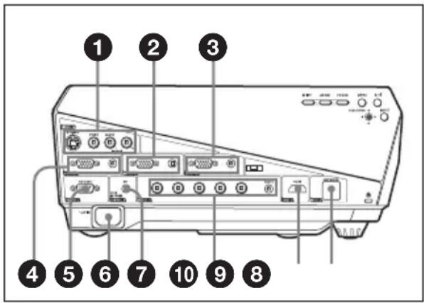
①VIDEO IN (Video input)
Connects to external video equipment. S VIDEO (mini DIN 4-pin)
Connects to the S video output (Y/C video output) of video equipment. VIDEO (phono type)
Connects to the composite video output of video equipment.
AUDIO input L (MONO)/R (phono type)
Connect to the audio output of video equipment. For stereo equipment use both the L and R jacks; for monaural equipment use the L (MONO) jack only.
②/③ INPUT A/INPUT B
Analog RGB connector (HD D-sub 15-pin, female)
Connects to external equipment such as a computer.
Connects to the monitor output of a computer using an optional cable.
AUDIO jack (stereo minijack)
To listen to sound output from a computer, connect via this jack to the audio output of the computer.
For details, see "Connecting a Computer" on page 17 and
"Connecting a VCR" on page 19.
④ OUTPUT
MONITOR connector (HD D-sub 15-pin, female)
Connect to the video input connector of the monitor. Outputs signals from the selected channel and computer signals only from among the signals from the INPUT A, INPUT B or INPUT C.
This connector does not output any signals from the INPUT D connector.
AUDIO jack (stereo minijack)
Connects to external active speakers. The volume of the speakers can be controlled by the VOLUME +/- keys on the Remote Commander.
When INPUT A, INPUT B or INPUT C is selected, the sound input to the AUDIO connector which is for INPUT A, INPUT B or INPUT C is output.
When VIDEO or S VIDEO is selected, the sound input to the AUDIO input connector of VIDEO IN is output.
⑤ REMOTE
RS-232C connector (D-sub 9-pin, female)
Connects to a computer to operate the projector from the computer.
⑥ AC IN socket
Connects the supplied AC power cord.
⑦CONTROL S IN/PLUG IN POWER (DC 5V output) jack (stereo minijack)
Connects to the control S out jacks of Sony equipment. Connects to the CONTROL S OUT jack on the supplied Remote Commander when using it as a wired Remote Commander. In this case, when a stereo cable is used, you do not need to install batteries in the Remote Commander as the power is supplied from this jack.
8 INPUT C
Analog RGB/Component connectors (R/R-Y/P R , G/Y, B/B-Y/P B , HD, VD) (BNC type)
We recommend using this terminal when signals are to be transmitted over greater distance than usual, such as when the projector is suspended from a ceiling.
Computer, component (R-Y/Y/B-Y), HDTV or DTV (DTV GBR, DTV YP B P R ) signal can be selected.
AUDIO (stereo minijack)
Connects to the audio output on a computer.
⑨ INPUT D
Digital RGB/Component connector (HDMI) (accepts HDCP)
Connects to a video output connector on video equipment or a computer equipped with HDMI/DVI output connector (digital).
10 INPUT E
NETWORK connector (RJ-45)
Connects to the LAN cable when the network function is in use.
CAUTION
For safety, do not connect the connector for peripheral device wiring that might have excessive voltage to this port.
Follow the instructions for this port.
Remote Commander
The keys that have the same names as those on the control panel function identically.
![graph TD A["21"] --> B["COMMAND OFF • ON"] B --> C["INPUT A INPUT B INPUT C"] C --> D["INPUT D INPUT E MIR S/OT"] D --> E["VIDEO S/VIDEO"] E --> F["MENU NPA +"] F --> G["ENTER"] G --> H["+"] H --> I["RESET"] I --> J["SHIFT ZOOM FOCUS"] J --> K["ASPECT KEY STONE"] K --> L["D ZOOM MUTING VOLUME"] L --…](/content/2026/05/1127532/images/b7ff81590a5fe005d855223f2ae9f33fa91bae7b68da5057e881b354a11d5e0b.jpg)
①I/⏻ (On/Standby) key
② INPUT A/B/C/D/E keys
Selects the input signal output from the connector of the same name as those of the Remote Commander.
③ AIR SHOT key
Displays the Network Presentation Home.
For details, see Operating Instructions for Network (stored on the CD-ROM).
④APA (Auto Pixel Alignment) key
Automatically adjusts a picture to its clearest while a signal is input from a computer.
For details, see “APA” in “The Screen Menu” on page 31.
⑤ ENTER key
⑥RESET key
Resets the value of an item to its factory preset value. This key functions when a setting item is displayed on the screen.
⑦ KEYSTONE (Vertical trapezoidal distortion correction) key
Adjusts the vertical trapezoidal distortion of the image manually. When you press this key, the V Keystone menu is displayed. Use the arrow keys (↑/↓/←/→) for adjustment.
⑧ASPECT key
Select the aspect ratio of the picture. Each time you press this key the aspect ratio changes according to the input signals.
⑨VOLUME +/- keys
10FREEZE key
Freezes the projected picture. To cancel the frozen picture, press the key again.
⑪ID MODE 1/2/3 keys
When you apply the same identification number as the projector to a Remote Commander you can easily adjust or control each projector with a Remote Commander whenever you use two or more projectors in one room.
For details, see "ID Mode" in the Installation menu on page 39.
⑫CONTROL S OUT jack (stereo mini-jack)
Connects to the CONTROL S IN jack on the projector with the connecting cable (not supplied) when using the Remote Commander as a wired one. In this case you do not need to install the batteries since the power is supplied via the CONTROL S IN jack on the projector.
13MUTING keys
Cut off the picture and sound.
- PIC: Cuts off the picture. Press again to restore the picture.
- AUDIO: Press to temporarily cut the audio output from the speaker or audio signal from the AUDIO jack of OUTPUT. Press again or press the VOLUME+ key to restore the sound.
14D ZOOM (Digital Zoom) +/- key
This function is not provided in this projector.
15ZOOM +/- keys
Adjusts the picture size.
16 FOCUS +/- keys
Adjusts the picture focus.
⑰SHIFT +/- keys
Adjusts the vertical/horizontal position of the picture.
18 ↑/↓/←/→ keys (Arrow)
Used to enter the settings of items in the menu or make adjustment for zoom, focus or shift.
19MENU key
20 COMMAND ON/OFF switch
When this switch is set to OFF, the keys on the Remote Commander do not function. This saves battery power.
⑳Infrared transmitter
To install batteries
1 Push and slide the lid to open it, then install the two size AA (R6) batteries (supplied) with the correct polarity.
While pressing the lid, slide it.

Be sure to install the battery from the ⊖ side.

2 Replace the lid.
Notes on Remote Commander operation
• Make sure that nothing obstructs the infrared beam between the Remote Commander and the remote control detector on the projector. Direct the Remote Commander toward the front or rear remote control detector.
- The operation range is limited. The shorter the distance between the Remote Commander and the projector is, the wider the angle within which the commander can control the projector becomes.
CAUTION
Danger of explosion if battery is incorrectly replaced.
Replace only with the same or equivalent type recommended by the manufacturer.
When you dispose of the battery, you must obey the law in the relative area or country.
Installing the Projector
The following table gives an example of installing the standard lens supplied with VPL-FE40/FX40/FX41/FW41.
For details on installation, ceiling installation or when you use an optional lens, be sure to refer to the operating instructions of “Installation Manual for Dealers”.
The distance between the lens and the screen varies depending on the size of the screen. Use the following table as a guide.

VPL-FE40/FX40/FX41
(When an SXGA+ (VPL-FE40)/XGA (VPL-FX40/FX41) signal is input)
Unit: m (feet)
| Screen size (inches) | 40 60 | 80 100 | 120 150 | 200 300 | 400 500 | 600 | |||||
| Minimum Distance | 1.5(4.9) | 2.3(7.4) | 3.0(9.9) | 3.8(12.5) | 4.6(15.0) | 5.7(18.8) | 7.7(25.2) | 11.6(37.9) | 15.4(50.6) | 19.3(63.3) | 23.2(76.0) |
| Maximum Distance | 1.9(6.2) | 2.9(9.5) | 3.9(12.7) | 4.8(15.9) | 5.8(19.1) | 7.3(23.9) | 9.7(32.0) | 14.6(48.0) | 19.5(64.1) | 24.4(80.2) | 29.4(96.3) |
There may be a slight difference between the actual value and the design value shown in the table above.
VPL-FW41
(When “Aspect” on the Screen menu is set to “Full 2” or “Full”)
Unit: m (feet)
| Screen size (inches) | 40 60 | 80 100 | 120 150 | 200 300 | 400 500 | 600 | |||||
| Minimum Distance | 1.6(5.1) | 2.4(7.8) | 3.2(10.4) | 4.0(13.1) | 4.8(15.8) | 6.0(19.8) | 8.1(26.4) | 12.1(39.7) | 16.2(53.1) | 20.2(66.4) | 24.3(79.7) |
| Maximum Distance | 2.0(6.5) | 3.0(9.9) | 4.1(13.3) | 5.1(16.7) | 6.1(20.1) | 7.7(25.1) | 10.2(33.5) | 15.4(50.4) | 20.5(67.3) | 25.7(84.2) | 30.8(101.1) |
There may be a slight difference between the actual value and the design value shown in the table above.
For details on installation, See “Installation Manual for Dealers” on the CD-ROM.
Connecting the Projector
When you connect the projector, make sure to:
- Turn off all equipment before making any connections.
- Use the proper cables for each connection.
- Insert the cable plugs firmly; loose connections may increase noise and reduce performance of picture signals. When pulling out a cable, be sure to pull it out by the plug, not the cable itself.
When connecting to a LAN using a LAN cable, see “Operating Instructions for Network” stored on the CD-ROM.
Connecting a Computer
This section describes how to connect the projector to a computer. For more information, refer to the computer's instruction manual.
To connect a computer (Analog)
![graph TD A["Computer"] -->|to monitor output| B["Device"] B -->|to audio output| C["Port ①"] C -->|②| D["Port ②"] D --> E["Side"]](/content/2026/05/1127532/images/98d228e41a584f896a1b96646051f022f8f547dd34e128d2b5291c27eada1f72.jpg)
①Stereo audio connecting cable (not supplied) (Use a no-resistance cable.)
②HD D-sub 15-pin cable (not supplied)
Notes
- The projector accepts VGA, SVGA, XGA, WXGA, SXGA, SXGA+ and UXGA signals. However, we recommend that you set the output mode of your computer to the following mode for the external monitor.
VPL-FE40: SXGA+ VPL-FX40/FX41: XGA VPL-FW41: WXGA
- If you set your computer, such as a notebook computer, to output the signal to both your computer's display and the external monitor, the picture of the external monitor may not
appear properly. Set your computer to output the signal to only the external monitor.
For details, refer to the operating instructions supplied with your computer.
Note
To connect a Macintosh computer equipped with a video output connector of a type having two rows of pins, use a commercially available plug adaptor.
To connect a computer (Digital) or video equipment (Digital)
![graph TD A["Monitor"] -->|to DVI-D output connector| B["Computer"] A -->|to HDMI connector| C["DVD player"] style A fill:#f9f,stroke:#333 style B fill:#ccf,stroke:#333 style C fill:#cfc,stroke:#333](/content/2026/05/1127532/images/5419806dda45fea8ab1225379a9dd9e41540b5d5d44af6edf123f0d749a09459.jpg)
①HDMI-DVI-D cable (not supplied)
②HDMI cable (not supplied)
Note
Be sure to use the HDMI cable with an HDMI logo.
The HDMI connector of this projector is not compatible with DSD (Direct Stream Digital) Signal or CEC (Consumer Electronics control) Signal.
To attach the HDMI cable
Fix the cable to the cable tie holder next to the HDMI connector using a commercially available cable tie as in the illustration.
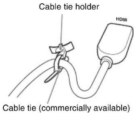
* Use a cable tie of less than 1.9 mm × 3.8 mm thickness.
Connecting a VCR
This section describes how to connect the projector to a VCR.
For more information, refer to the instruction manuals of the equipment you are connecting.
To connect to a video or S video output connector

①Audio connecting cable (not supplied) For stereo equipment use both the L and R jacks.
For monaural equipment use the L (MONO) jack only.
②Video cable (not supplied) or S-Video cable (not supplied)
To connect to a video GBR/Component output connector
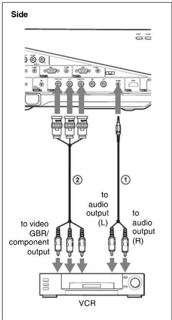
①Stereo audio connecting cable (not supplied) (Use a no-resistance cable.)
②BNC cable (not supplied)
Note
Set the aspect ratio using “Aspect” on the Screen menu according to the input signal.
Projecting
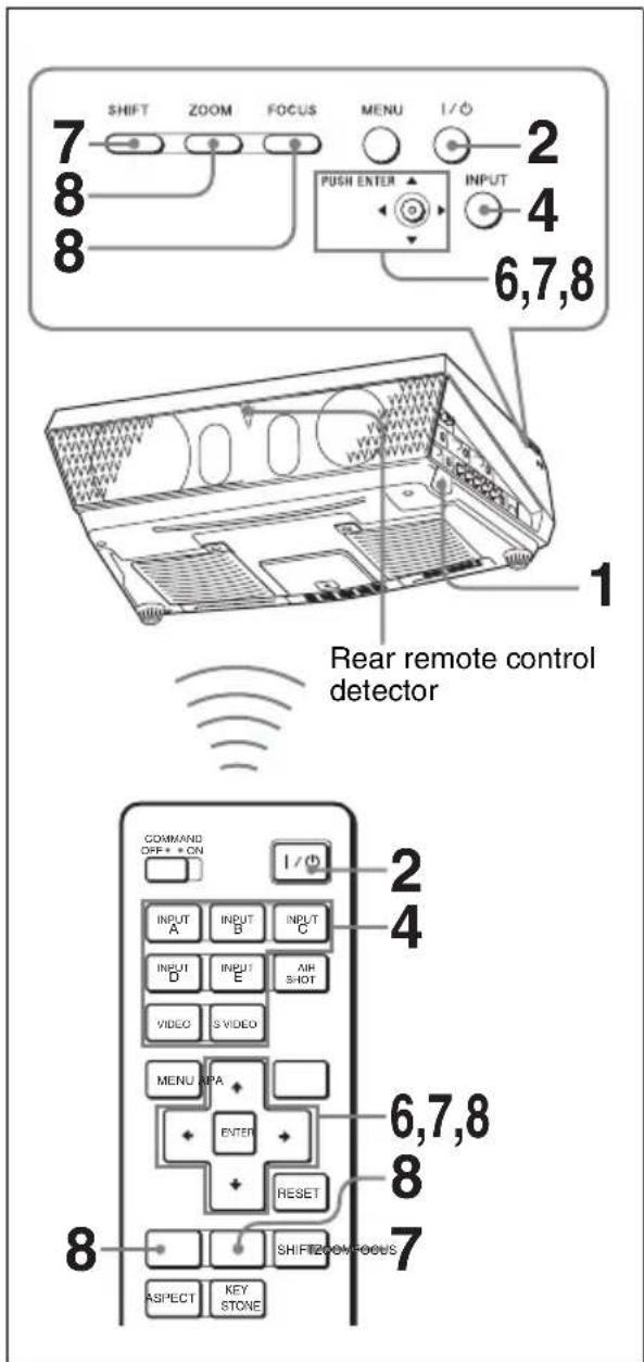
1 Plug the AC power cord into a wall outlet, then connect all equipment. The ON/STANDBY indicator lights in red and the projector goes into standby mode.
2 Press the I/⏻ key.
The ON/STANDBY indicator flashes in green, and then lights in green.
3 Turn on the equipment connected to the projector.
4 Press the INPUT key to select the input source.
You can select directly the input signal you want to project by pressing one key from among INPUT A, B, C, D or E on the Remote Commander.
Each time you press the INPUT key on the control panel, the input signal switches as follows:
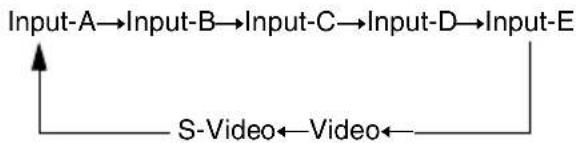
| To input from Press INPUT | to display |
| Computer, etc. connected to the INPUT A connector | Input-A |
| Computer, etc. connected to the INPUT B connector | Input-B |
| Computer/VCR, etc. connected to INPUT C connector | Input-C |
| Computer/VCR, etc. connected to INPUT D (Digital) connector | Input-D |
| Computer connected to LAN to use the network presentation function | Input-E |
| Video equipment connected to the VIDEO input connector | Video |
| Video equipment connected to the S VIDEO input connector | S-Video |
Smart APA (Auto Pixel Alignment) adjusts the picture of the connected equipment so that it is projected clearly.
Notes
- If “Auto Input Search” is set to “On,” the projector searches for the signals from the connected equipment and displays the input channel where the input signals are found.
For details, see "Auto Input Search" in the Function menu on page 36.
- The Smart APA feature is effective for the input (analog) signal from a computer only. (It is not effective for digital computer signal.)
5 Switch the equipment connected to output to the projector.
Depending on the type of your computer, for example a notebook, or an all-in-one LCD type, you may have to switch the computer to output to the projector by pressing certain keys (e.g., LCD/VGA, □/□, etc.), or by changing your computer's settings.
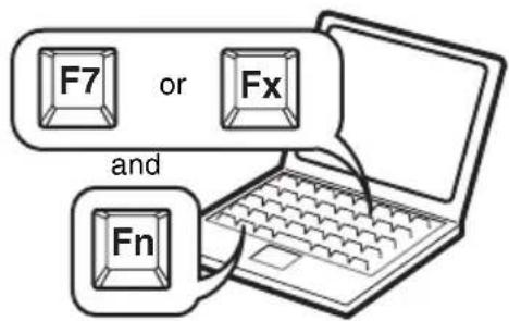
Note
The key used for switching the computer to output to the projector varies depending on the type of computer.
6 Adjust the upper, lower, left or right position of the picture using the ↑/↓/←/→ key while pressing the SHIFT key.
7 Adjust the size of the picture and the focus.
Press the FOCUS key and adjust the focus using the //←/→ keys. Press the ZOOM key and adjust the size of the picture using the //←/→ keys.
Note
The VPLL-1008 does not have the zoom function. To adjust the focus of the picture, turn the lens ring.
To adjust the tilt of the installation surface
If the projector is installed on an uneven surface, use the adjusters to keep the projector level.
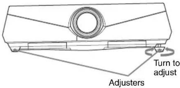
Notes
- Be careful not to let the projector down on your fingers.
- Do not push hard on the top of the projector with the adjuster extended. It may cause a malfunction.
Turning Off the Power
1 Press the I/⏻ key.
"POWER OFF? Please press I/ ① key again." appears to confirm that you want to turn off the power.
Note
The message disappears if you press any key other than the I/⏻ key, or if you do not press any key for approximately five seconds.
2 Press the I/⏻ key again.
The ON/STANDBY indicator flashes in green and the fan continues to run to reduce the internal heat. Also, the ON/STANDBY indicator flashes quickly. During this time, you will not be able to light up the ON/STANDBY indicator again with the I/⏻ key.
3 Unplug the AC power cord from the wall outlet after the fan stops running and the ON/STANDBY indicator lights in red. (except when using the Direct Power On/Off function and the Off & Go Function.)
When you cannot confirm the on-screen message
When you cannot confirm the on-screen message under certain conditions, you can turn off the power by holding the 1/1 key for about one second instead of the steps 1 and 2 above.
Note
The internal circuitry of the Off & Go and Direct Power On/Off functions may cause the fan to continue to operate for a short time even after the I/⏻ key is pressed to turn off the power and the ON/STANDBY indicator changes to red.
Selecting the Menu Language
You can select one of sixteen languages for displaying the menu and other on-screen displays. The factory setting is English. To change the menu language, proceed as follows:

1 Plug the AC power cord into a wall outlet.
2 Press the I/⏻ key to turn on the projector.
3 Press the MENU key.
The menu appears.
The menu currently selected is shown as a yellow button.

4 Press the or key to select the
(Setup) menu, then press the → or ENTER key.
The selected menu appears.


5 Press the ↑ or ↓ key to select "Language," then press the → or ENTER key.
![Setup Stat English 中Ls Netherlands High Français Star Italiano Pow Deutsch Volu Español Spe Português Inpu Pycckii Cok Svenska Lam Norsk 日本語 中文(简体字) 中文(國體字) 한국어 männ이ย عربي Set: [F] [B] Set: [S]](/content/2026/05/1127532/images/3d4dbf5c78ce80025e446d4ded65de327bdf98e38f2aed889c239a4d10138c36.jpg)
6 Press the ↑, ↓, ← or → key to select a language, then press the ENTER key.
The menu changes to the selected language.
To clear the menu
Press the MENU key.
The menu disappears automatically if a key is not pressed for one minute.
Security Lock
The projector is equipped with a security lock function. When you turn the power of the projector on, you are required to input the previously set password. If you do not input the correct password, you will not be able to project the picture.
Notes
- When the security lock becomes effective, you are required to input the password only when you turn the projector on after disconnecting or reconnecting the cable.
- You will not be able to use the projector if you forget your password and the password administrator is not available. Be please aware that using the security lock can prevent valid usage in such cases.
To use the security lock
1 Press the MENU key and then, on the Function menu, turn on the “Security Lock” setting.
2 Enter the password.
Use the MENU, ↑/↓/←/→, and ENTER keys to enter the four-digit password. (The default initial password setting is “ENTER, ENTER, ENTER, ENTER.” After this is entered you can put in your own password. Therefore, when you use this function for the first time, please input “ENTER” four times.)

Next, the screen for entering the new password is displayed. (Enter the password on this screen even if you want to keep the current password.)
Enter the password on this screen.

3 Enter the password again to confirm.

When “Security Lock enabled!” is displayed on the menu screen, the setting for security lock is completed.
If “Invalid Password!” is displayed on the menu screen, perform this procedure again from step 1.
4 Turn the main power off and disconnect the AC power cord.
The security lock is set to on, then it becomes effective. The screen used for entering the password is displayed when the power is turned on the next time.
Security certification
When the password screen is displayed, enter the password that was set. If you fail to enter the correct password after three tries, the projector cannot be used. In this case, press the I/↓ key to turn off the power.
To cancel the security lock
1 Press the MENU key, then turn off the "Security Lock" setting in the Function menu.
2 Enter the password.
Enter the password that was set.
Note
If you call the customer service center because you have forgotten the password, you will need to be able to verify the projector's serial number and your identity. (This process may differ in other countries/regions.) Once your identity has been confirmed, we will provide you with the password.
Other Functions
Direct Power On/Off Function
If you will be using a circuit breaker to turn the power for the entire system on and off, set the direct power on function to “On.” You can turn the power on/off without pressing the power key on the projector. After the power is turned off, the internal circuitry will cause the fan to automatically operate for a certain time.
Note
The fan does not turn in the VPL-FX41/FW41. However, the Direct Power On/Off function has the same performance.
Off & Go Function
If you are leaving the conference room immediately, turn the projector off. Then you may unplug the AC power cord. It does not matter. After the AC power cord is unplugged, the fan runs for a certain time automatically.
Notes
- The fan does not turn in the VPL-FX41/FW41. However, the Off & Go function has the same performance.
- You need more than 15 minutes for a charge power supply. If the projector has been on for less than 15 minutes, the fan might not turn enough as a result of inadequate charging. If the projector has been on for a short time, unplug the AC power cord from the wall outlet after the power off and the ON/STANDBY indicator lights in red (except with the VPL-FX41/FW41).
- When the power is turned on soon after it has been turned off, it may take some time until the lamp will light on.
Effective Tools for Your Presentation
To freeze the image projected (Freeze function)
Press the FREEZE key. “Freeze” appears when the key is pressed. This function works when a signal from a computer is input. To restore the original screen, press the FREEZE key again.
Controlling the Computer Using a Presentation Tool, RM-PJPK1 (not supplied) (When Using the Network Presentation Function)
When you are using the network presentation function to project the picture from a computer, you can perform some operations for a slide show using a presentation tool (not supplied). The following keys on the presentation tool are usable.
| Key Function | |
| LASER Emits a laser beam. | * |
| ↔ SLIDE → Changes | the slides in the forward/backward direction. |
| B Displays/cancels a | black screen during the slide show. |
* Even if the network presentation function is not used, the LASER key can be used.
Notes
- If there is any obstruction between the presentation tool and the remote control detector on the projector, the presentation tool may not function properly.
- A black screen may not be displayed even if you press the “B” key depending on the operating system (OS) of the language of your computer.
- When you use the presentation tool, set “ID Mode” in the Installation menu to “All” or “1.”
▶Adjustments and Settings Using a Menu
Using a MENU
The projector is equipped with an on-screen menu for making various adjustments and settings. Some of the adjustable/setting items are displayed in a pop-up menu, in a setting menu or adjustment menu with no main menu, or in the next menu window. If you select an item name followed by an arrow (▶), the next menu window with the setting items appears.
To change the on-screen menu language, see "Selecting the Menu Language" on page 23.
Display items
Input signal indicator

Input signal indicator
Shows the selected input channel. ✗ displayed when no signal is input. You can hide this indicator using "Status" on the Setup menu.
1 Press the MENU key. The menu appears.

2 Use the ↑ or ↓ key to select a menu, then press the → or ENTER key.
The items that can be set or adjusted with the selected menu appear. The item presently selected is shown in yellow.

3 Select an item.
Use the ↑ or ↓ key to select the item, then press the → or ENTER key. The setting items are displayed in a pop-up menu, in a setting menu, in an adjustment menu or in the next menu window.
Pop-up menu

Setting menu

Adjustment menu

Next menu window
Setting items
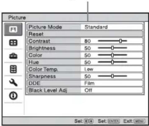
4 Make the setting or adjustment of an item.
- When changing the adjustment level:
To increase the number, press the or → key.
To decrease the number, press the ↓ or ← key.
Press the ENTER key to restore the previous screen.
- When changing the setting:
Press the or key to change the setting.
Press the ENTER key to restore the previous screen.
You can restore the previous screen using ← depending on the selected item.
To clear the menu
Press the MENU key.
The menu disappears automatically if a key is not pressed for one minute.
To reset items that have been adjusted
To reset the setting of the items, there are the following two ways.
- Select "Reset" in the Picture menu.
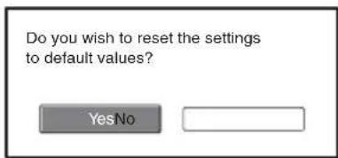
Select "OK" when the screen display appears. The following settings are reset to their factory preset values:
The items that can be reset are as follows: "Contrast," "Brightness," "Color," "Hue," "Color Temp," "Sharpness," "DDE,"
"Black Level Adj." and "Gamma Mode" in the Picture menu.
- Press the RESET key on the Remote Commander.
To reset the value of an item back to its factory preset value, press the RESET key while a setting item is displayed on the screen.
Unadjustable items
The adjustable items are limited depending on the input signals. The items that cannot be adjusted or set do not appear in the menu.
For details, see page 40.
Storage of the settings
The settings are automatically stored in the projector memory.
If no signal is input
If there is no input signal, “Cannot adjust this item.” appears on the screen.
The Picture Menu
The Picture menu is used for adjusting the picture.
Items that can be adjusted or set depend on the kind of input signals.
For details, see "Input signals and adjustable/setting items" on page 40.
When the video signal is input When the signal is input from a computer


| Setting items Functions Initial setting | ||
| Picture Mode Selects the picture mode.• Dynamic: Emphasizes the contrast to produce a “dynamic” picture.• Standard: Normally select this setting. If the picture has roughness with the “Dynamic” setting, this setting reduces the roughness. | Standard | |
| Reset The following settings are initialized to their factory preset values: “Contrast,” “Brightness,” “Color,” “Hue,” “Color Temp,” “Sharpness,” “DDE,” “Black Level Adj.,” and “Gamma Mode” in the Picture Mode. | - | |
| Contrast Adjusts the white area of pictures (white level).The higher the setting, the greater the contrast. The lower the setting, the lower the contrast. | 80 | |
| Brightness Adjusts the brightness of the picture.The higher the setting, the brighter the picture. The lower the setting, the darker the picture. | 50 | |
| Color Adjusts the intensity of the color density.The higher the setting, the greater the intensity. The lower the setting, the lower the intensity. | 50 | |
| Hue Adjusts the color tone.The higher the setting, the more greenish the picture becomes. The lower the setting, the more reddish the picture becomes. | 50 | |
| Color Temp. Adjusts the color temperature.• High: Gives white colors a blue tint.• Low: Gives white colors a red tint. | Low | |
| Sharpness Sharpens the outline of the picture, or reduces the noise.The higher the setting, the sharper the picture. The lower the setting, the softer the picture, thus reducing the noise. | 50 | |
| DDE (Dynamic Detail Enhancer) | According to the film source you have selected, make a setting for playback.Film: Normally, select this option. Reproduces the 2-3 Pull-Down film sources with smooth picture movement. When the video signal with a format other than the 2-3 Pull-Down is input, “Progressive” is automatically selected.Progressive: Converts an interlace format video signal to a progressive format.Off: Plays a video signal in an interlace format without converting. | Film |
| Black Level Adj. (Adjust) | Produces a bolder, dynamic picture.Set according to the input signal source.High: Gives higher emphasis to the black color.Low: Gives lower emphasis to the black color.Off: Cancels this feature. | Off |
| Gamma Mode Selects a gamma correction curve.Graphics: Improves the reproduction of halftones. Photos can be reproduced in natural tones.Text: Contrasts black and white. Suitable for images that contain lots of text. | Graphics | |
The Screen Menu
The Screen menu is used to adjust the input signal. You can also adjust the aspect ratio of the picture.
Items that can be adjusted or set depend on the kind of input signals.
For details, see "Input signals and adjustable/setting items" on page 40.


| Setting items Functions Initial setting | ||
| Aspect (When the video signal is input) | You can set the aspect ratio of the picture to be displayed for the current input signal. This item is enabled only when an video signal (preset memory numbers 1 to 15) is input.4:3: Select to view a picture with normal 4:3 aspect ratio.16:9: Select to view a picture squeezed.Zoom (VPL-FE40/FX40/FX41): Select to view a squeezed picture with black bands displayed on both sides.Zoom (VPL-FW41): A 16:9 aspect ratio picture is enlarged vertically and horizontally in the same ratio to fill the screen. Black bands may remain on the top and bottom of the screen.Full: Displays a picture on the whole of the screen. | Set according to the input signal |
| Aspect (When the PC signal is input) | You can set the aspect ratio of the picture to be displayed for the current input signal. This item is enabled only when an PC signal (preset memory numbers 21 to 56) is input.Full 1: Displays a picture vertically or horizontally to fill the screen without changing the aspect ratio of the original picture.Full 2: Displays a picture on the whole of the screen.Normal: Displays the picture while matching one pixel of input picture element to that of the LCD. The picture will be clear but the picture size will be smaller.4:3: Makes the aspect ratio 4:3.16:9: Makes the aspect ratio 16:9. | Set according to the input signal |
| Over Scan Hides the | outline of the picture.• On: Hides the outline of the input picture. Select this setting when noise appears along the edge of the picture.• Off: Projects the whole of the input picture.To adjust the displayable area within the four directions of the screen, refer to “Blanking” in the Installation menu (page 39) | On |
| V Center Adjusts the | whole picture by moving up and down on the screen. As the selected number increases, the screen moves up, and as the selected number decreases, the screen moves down.NoteThis setting is adjustable only when “Aspect” is set to “Zoom” on VPL-FW41. | 0 |
| Vertical Size Reduces | or enlarges the picture vertically. The screen is enlarged as the setting is increased and reduced as the setting decreases. If the subtitle of a movie, etc. cannot be seen, use this together with “V Center.”NoteThis setting is adjustable only when “Aspect” is set to “Zoom” on VPL-FW41. | 0 |
| Adjust Signal Set according to | the input signal | |
| APA (Auto Pixel Alignment) | Pressing ENTER key automatically adjusts the “Phase,” “Pitch” and “Shift” to position the image correctly on a screen. | |
| Phase Adjusts the | dot phase of the panel and the computer signal.Adjust the picture to the point where it looks clearest. | |
| Pitch Adjusts the | horizontal size of the picture from a computer.The higher the setting, the wider the picture. The lower the setting, the narrower the picture. Adjust the setting to match the number of dots of the input signal. | |
| Shift Adjusts the | position of the picture.• H: As the setting for H (horizontal) increases, the picture moves to the right, and as the setting decreases, the picture moves to the left. Use ← / →key to adjust the horizontal position.• V: As the setting for V (vertical) increases, the picture moves up, and as the setting decreases, the picture moves down. Use ↑ / ↓ key to adjust the vertical position. | |
Notes
- Note that if the projector is used for profit or for public viewing, modifying the original picture by switching to the aspect mode may constitute an infringement of the rights of authors or producers, which are legally protected.
- For Aspect, “Aspect” itself or a part of the setting items cannot be displayed on the screen according to the input signal. Also, “Full 1” and “Full 2,” or “Full 1” and “4:3” may become the same images.
About the Preset Memory No.
This projector has 48 types of preset data for input signals (the preset memory). When a preset signal is input, the projector automatically detects the signal type and recalls the data for the signal from the preset memory to adjust it to an optimum picture. The memory number and signal type of that signal are displayed on the Infomation menu (See page 40). You can also adjust the preset data through the Screen menu.
This projector has 20 types of user memories for Input-A into which you can save the setting of the adjusted data for an unpreset input signal.
When an unpreset signal is input for the first time, a memory number is displayed as 0. When you adjust the data of the signal using the Screen menu, it will be registered in the projector. If more than 20 user memory items are registered, the newest memory always overwrites the oldest one.
See the chart on page 53 to find if the signal is registered in the preset memory.
Note
For VPL-FE40/FX40/FX41, a part of the screen is displayed in black when “Aspect” is set to an option other than ” “4:3.”
For VPL-FW41, a part of the screen may be displayed in black when “Aspect” is set to an option other than “Full 1” or “Full 2.”
The Setup Menu
The Setup menu is used for changing the settings of the projector.
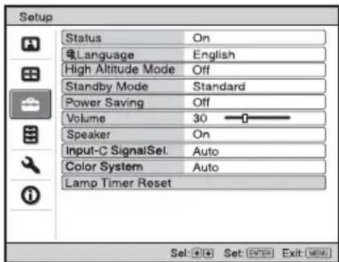
| Setting items Functions Initial setting | ||
| Status Sets whether or not the on-screen display is displayed. Set to “Off” to turn off the on-screen displays except for the menus, message when turning off the power, and warning messages. | On | |
| Language Selects the language used in the menu and on-screen displays. Available languages are: English, Dutch, French, Italian, German, Spanish, Portuguese, Russian, Swedish, Norwegian, Japanese, Chinese (Simplified Chinese), Chinese (Traditional Chinese), Korean, Thai and Arabic. | English | |
| High Altitude Mode | Use this item when using the projector at high altitudes.• On: Use this setting when using the projector at an altitude of 1,500 m or higher.• Off: Use this setting when using the projector at normal altitudes. | Off |
| Standby Mode Lower | s the power consumption in standby mode. When set to “Low”, the power consumption in standby is lowered. | Standard |
| Power Saving Sets the power saving mode. When set to “On”, the projector goes into power saving mode if no signal is input for 10 minutes. At that time, the ON/STANDBY indicator lights in orange, then the screen becomes dark. In power saving mode, the power saving mode is cancelled if a signal is input or any button is pressed. If you do not want to set the projector to power saving mode, select “Off”. | Off | |
| Volume Adjusts the volume. 30 | ||
| Speaker Set to “Off” | to cut the sound of the internal speakers. When set to “Off,” “Speaker: Off” appears on the screen when you turn on the power. | On |
| Input-C Signal Sel. | Selects the type of signal input from the equipment connected to the INPUT C connector.Selects the type of signal input from the equipment by selecting “Input-C” with the INPUT key.Auto: Selects the input signal type automatically.Computer: Inputs the signal from a computer.Video GBR: Inputs the signal from a TV game or HDTV broadcast.Component: Inputs the component signal from a DVD player/recorder, Blu-ray Disc player, digital tuner, etc. | Auto |
| Color System | Selects the color system of the input signal.Auto: Selects the color system of the input signal automatically from among NTSC3.58, PAL, SECAM, NTSC4.43, PAL-M, PAL- N , or PAL 6 0.“ NTSC3.58”–“PAL-N”: Allows you to set the color system to the selected system manually. | Auto |
| Lamp Timer Reset W | When replacing the lamps, reset the lamp timer. – | |
Notes
- If you turn on “High Altitude Mode” to “On” at an altitude less than 1,500 m (4,921 feet), the projector may reduce the reliability of the lamp.
- When “High Altitude Mode” is set to “On”, the number of turns of the fan increases, and the fan noise becomes slightly louder.
- When “Standby Mode” is set to “Low,” the network presentation function and network control function cannot be operated while it is in standby mode.
- When the input signal is not displayed correctly even if “Input-C Signal Sel.” set to “Auto,” select the item according to the input signal.
- Normally, set “Color System” to “Auto.” If the picture is distorted or colorless, select the color system appropriate for the input signal.
The Function Menu
The Function menu is used for changing the settings of the various functions of the projector.

| Setting items Functions Initial setting | ||
| Smart APA The APA | (Auto Pixel Alignment) automatically adjusts “Phase,” “Pitch” and “Shift” in the Screen menu for the input signal from a computer. ·On: When a signal is input from a computer, the APA functions automatically so that the picture can be seen clearly. You can adjust the picture by pressing the APA key on the Remote Commander even if “Smart APA” set to “On.” ·Off: The APA functions when you press the APA key on the Remote Commander. | On |
| Auto Input Search D | etects the input signal and displays the detected input signal automatically when the INPUT key is pressed. When set to “On”, the projector detects whether a Input-A, Input-B, Input-C, Input-D, Input-E, Video or S Video signal is input when the input connector with effective signals is automatically selected by pressing INPUT key. “Input-E” is displayed always. Set this to “Off” when you want to select an input selector with no input signal, or you want to switch the setting manually. | Off |
| Test Pattern Displays | the test pattern. When set to “On,” a test pattern appears on the screen to be used when adjusting the lens with “Focus,” “Zoom,” and “Shift,” or correcting the screen proportions with “V Keystone.” A test pattern does not appear when this item is set to “Off.” | Off |
| Background Selects | the background color of the screen when no signal is input. You can select “Black” or “Blue”. | Blue |
| Setting items Functions Initial setting | ||
| Panel Key Lock Locks all the control panel keys on the side panel of the projector so that the projector can be operated only with the Remote Commander.To lock the control panel keys, set to “On.”When it is set to “On,” keeping the I/⏻ key on the control panel pressed for 10 seconds turns the projector on when it is in standby mode, and turns the projector to standby mode when the power is on. If you press and hold the MENU key for about 10 seconds when the power is on, the lock will be released and “Panel Key Lock” is automatically set to “Off.” | Off | |
| Security Lock Turns on the projector’s security lock function.When set to “On,” turns on the security lock function, which locks the projector once a password has been set.For details, see “Security Lock” on page 24. | Off | |
Notes
- Press the APA key when the full image is displayed on the screen. If the projected image includes a black portion around it, the APA function will not work properly and some parts of the image may not be displayed on the screen.
- You can cancel the adjustment by pressing the APA key again while “Adjusting” appears on the screen.
- The picture may not be adjusted properly depending on the type of input signal.
- Adjust the “Phase,” “Pitch,” and “Shift” items in the Screen menu when you adjust the picture manually.
The Installation Menu
The Installation menu is used for changing the settings of the projector.
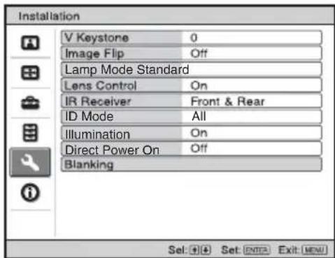
| Setting items Functions Initial setting | ||
| V Keystone Corrects the vertical trapezoidal distortion of the picture.When the bottom of the trapezoid is longer than the top(☐) : Sets a lower value (− direction).When the top of the trapezoid is longer than the bottom(☐) : Sets a higher value (+ direction). | 0 | |
| Image Flip Flips the picture on the screen horizontally and/or vertically.Use this item for installation for the backside projection or ceiling installation.HV: Flips the picture horizontally and vertically.H: Flips the picture horizontally.V:Flips the picture vertically.Off: The picture does not flip. | Off | |
| Lamp Mode Sets the lamp brightness used during the projection.High: Illuminates the projected image brightly.Standard: Reduces fan noise and power consumption.The brightness of the projected image will be lower compared with the “High” setting. | Standard | |
| Lens Control Avoids any operation of the lens such as “Focus,” “Zoom,” and “Shift,” by mistake.When set to “On,” you can adjust the projection lens using “Focus,” “Zoom,” and “Shift.” After you make this adjustment, it is recommended that you set this item to “Off” to avoid any operation of the lens. When set to “Off,” the FOCUS, ZOOM and SHIFT keys do not work. | On | |
| IR Receiver Selects the remote control detectors (IR Receiver) on the front and rear of the projector.Front & Rear: Activates both the front and rear detectors.Front: Activates the front detector only.Rear: Activates the rear detector only. | Front & Rear | |
| Setting items Functions Initial setting | ||
| ID Mode Assigns | an ID number (1 to 3) to the projector when you want control two or more projectors individually with the supplied Remote Commander. When this item is set to “1,” you can control the projector with the Remote Commander with the ID MODE key set to “1.” When it is set to “All,” you can control all the projectors with the Remote Commander independently of the ID MODE keys of the Remote Commander. | All |
| Illumination Selects | whether the SONY logo on the top panel of the projector lights when the projector is on. | On |
| Direct Power On Set to “On” if you are using a circuit breaker to turn the power on/off the entire system. You can turn the power on/off without pressing the I/⏻ key on the projector. | Off | |
Blanking Adjust the displayable area within the four directions of the screen.Select each screen edge “left / right / up / bottom” on the Blanking adjustment screen with ↑ / ↓ key. Adjust the desired Blanking value with ← / → key. | 0 | |
Notes
- Since the V keystone function is an electronic correction, sometimes the image will be deteriorated.
- Depending on the picture position adjusted with the lens shift feature, the aspect ratio of the picture may change from the original or picture distortion may occur with V Keystone adjustment.
- When both Blanking and V Keystone are adjusted at the same time, Blanking may not function properly. When you use Blanking, set the V Keystone to “0.”
- Since the displayable area becomes narrower when Blanking value is adjusted, information necessary on Input-E may not be displayed.
The Information Menu
The Information menu displays the model name, serial number, the horizontal and vertical frequencies of the input signal and the cumulated hours of usage of the lamp.

| Setting items Functions | |
| Model Name Displays the model name. | |
| Serial No. Displays the serial number. | |
| fH (horizontal frequency) | Displays the horizontal frequency of the input signal. |
| fV (vertical frequency) | Displays the vertical frequency of the input signal. |
| Memory number Displays the preset memory number of the input signal. | |
| Signal Type Displays the type of the input signal. | |
| Lamp Timer Indicates how long the lamp has been turned on (total usage). | |
Notes
- fH (horizontal frequency) and fV(vertical frequency) may not be displayed depending on the input signal used on the projector.
- You cannot change the displays listed above.
Input signals and adjustable/setting items
Some of the items in the menus cannot be adjusted depending on the input signal as indicated in the following tables. The items that cannot be adjusted are not displayed in the menu.
Picture menu
| Item Input signal | |||||
| Video/S-Video (Y/C) | Component Video | GBR Computer Network | |||
| Picture Mode | ● | ● | ● | ● | ● |
| Contrast | ● | ● | ● | ● | ● |
| Brightness | ● | ● | ● | ● | ● |
| Color | ●*1 | ● | ● | - | |
| Hue | ●*2 | ● | ● | - | |
| Color Temperature | ● | ● | ● | ● | ● |
| Sharpness | ● | ● | ● | - | |
| DDE | ● | ●*4 | ●*4 | - | - |
| Black Level Adj. | ● | ● | ● | - | |
| Gamma Mode | - | - | ●*3 | ● | ● |
● : Adjustable/can be set
- : Not adjustable/cannot be set
*1 : Except B & W
*2: NTSC3.58 and NTSC4.43 only, except B & W
*3: Preset memory No. 3, 4 only
*4: Preset memory No. 3, 4, 7, 8 only
Screen menu
| Item Input signal | |||||
| Video/S-Video (Y/C) | Component Video | GBR Computer | Network | ||
| Aspect | ● | ● | ● | ● | |
| Over Scan | - ● | ● | - | - | |
| V Center | ●*5 | ●*5 | ●*5 | - | - |
| Vertical Size | ●*5 | ●*5 | ●*5 | - | - |
| Adjust Signal | |||||
| APA | - | - | - | ●6 | - |
| Phase | - | - | - | ●6 | - |
| Pitch | - | - | - | ●6 | - |
| Shift | - ● | ● | ● | - | |
● : Adjustable/can be set
- : Not adjustable/cannot be set
*5: Adjustable only when "Aspect" is set to "Zoom" on VPL-FW41
*6: Except HDMI input
Replacing the Lamp
The lamp used as a light source is a consumable product. Thus replace this lamp with a new one in the following cases.
- When the lamp has burnt out or dims
- "Please replace the Lamp and clean the Filter." appears on the screen.
- The LAMP/COVER indicator flashes in red. (Repetition rate of 3 flashes)
The lamp life varies depending on conditions of use.
Use an LMP-F270 Projector Lamp as the replacement lamp.
Use of any other lamps than the LMP-F270 may cause damage to the projector.
Caution
The lamp remains hot after the projector is turned off with the I/⏻ key. If you touch the lamp, you may burn your finger. When you replace the lamp, wait for at least an hour for the lamp to cool.
Notes
- If the lamp breaks, consult with qualified for personal.
- Pull out the lamp by holding the knob. If you touch the lamp, you may be burned or injured.
- When removing the lamp, make sure it remains horizontal, then pull straight out. Do not tilt the lamp. If you pull out the lamp while it is tilted and if the lamp breaks, the pieces may scatter, causing injury.
1 Turn off the projector, and disconnect the AC power cord from the AC outlet.
Note
When replacing the lamp after using the projector, wait for at least an hour for the lamp to cool.
2 Open the lamp cover by loosening the three screws with a Phillips screwdriver.
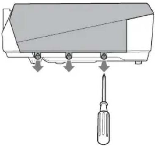
3 Remove the lamp cover by lifting it forward with the fingers placed on the slit of the projector.

4 Loosen the two screws on the lamp unit with the Phillips screwdriver (1), hold the knob (2), then pull out the lamp unit.

5 Insert the new lamp all the way in until it is securely in place (1). Tighten the two screws (2).

Notes
- Be careful not to touch the glass surface of the lamp.
- The power will not turn on if the lamp is not secured properly.
6 Restore the lamp cover to the original position and tighten the three screws with the phillips screwdriver.
Note
Be sure to attach the lamp cover securely as it was. If not, the projector cannot be turned on.
7 Connect the power cord. The ON/STANDBY indicator lights in red.
8 Press the I/⏻ key to turn the projector on.
9 Press the MENU key, and then select the Setup menu.
10 Select "Lamp Timer Reset", and then press the ENTER key. A message is displayed.
11 Select "Yes", and then press the ENTER key. The Lamp Timer is initialized to 0, and "Lamp Timer Reset Complete!" is displayed in the menu screen.
12Select "OK."
Caution
Do not put your hands into the lamp replacement slot, and do not allow any liquid or other objects into the slot to avoid electrical shock or fire.
Note
To erase a message, press any key on the control panel of the projector or on the Remote Commander.
Disposal of the used lamp
For the customers in the USA
Lamp in this product contains mercury. Disposal of these materials may be regulated due to environmental considerations. For disposal or recycling information, please contact your local authorities or the Electronic Industries Alliance (www.eiae.org).
Cleaning the Air Filter
The air filter should be cleaned whenever you replace the lamp.
Remove the air filter, and then remove the dust with a vacuum cleaner.
The time needed to clean the air filter will vary depending on the environment or how the projector is used.
1 Turn the power off and unplug the power cord.
2 Remove the air filter covers.
The air filter of the VPL-FX41/FW41 is on one side only.

3 Remove the air filter from the each claws (6 positions) on the air filter cover.

4 Clean the air filter with a vacuum cleaner.
5 Attach the air filter so that it fits into the each claws (6 positions) on the air filter covers and replace the cover.
Caution
If you neglect to clean the air filter, dust may accumulate, clogging it. As a result, the temperature may rise inside the unit, leading to a possible malfunction or fire.
Notes
- If the dust cannot be removed from the air filter, replace the air filter with a new one. For details on new air filter, consult with qualified Sony personnel.
- Be sure to attach the air filter cover firmly; the power can not be turned on if it is not closed securely.
• The air filter has face and reverse sides. Attach the air filter so that the frames on the air filter are visible.
• To erase a message, press any key on the control panel of the projector or on the remote commander.
Troubleshooting
If the projector appears to be operating erratically, try to diagnose and correct the problem using the following instructions. If the problem persists, consult with qualified Sony personnel.
Power
| Symptom Cause and Remedy | |
| The power is not turned on. | The power has been turned off and on with the I/⏻ key at a short interval.Wait for about 60 seconds before turning on the power (see page 22).The lamp cover is not secured.Close the lamp cover securely (see page 43).The air filter cover is detached.Attach the air filter cover securely (see page 44). |
Picture
| Symptom Cause and Remedy | |
| No picture. • A cable is disconnected or the connections are wrong.→ Check that the proper connections have been made (see page 17).• The connections are wrong.→ This projector is compatible with DDC2B (Digital Data Channel 2B). If your computer is compatible with DDC, turn the projector on according to the following procedures.1 Connect the projector to the computer.2 Turn the projector on.3 Start the computer.• Input selection is incorrect.→ Select the input source correctly using the INPUT key (see page 20).• The picture is muted.→ Press the PIC MUTING key to release the picture muting (see page 15).• The computer signal is not set to output to an external monitor or set to output both to an external monitor and a LCD monitor of a computer.→ Set the computer signal to output only to an external monitor (see page 17). | |
| The picture is noisy. • Noise | may appear on the background depending on the combination of the number of dots input from the computer and the numbers of pixels on the LCD panel.→ Change the desktop pattern on the connected computer.• Input a video signal with the jitter.→ Use a TBC (Time Base Corrector) to try to reduce video jitter. |
| The picture from the INPUT C connector is colored strangely. | The setting of “Input-C Signal Sel.” in the Setup menu is incorrect.→ Select “Computer,” “Video GBR” or “Component” correctly according to the input signal (see page 35). |
| “Please check Input-C Signal Sel.” appears in spite of inputting the correct signal from INPUT C. | The setting of “Input-C Signal Sel.” in the Setup menu is incorrect.→ Select “Computer,” “Video GBR” or “Component” correctly according to the input signal (see page 35). |
| On-screen display does not appear. | “Status” in the Setup menu has been set to “Off.”→ Set “Status” in the Setup menu to “On” (see page 34). |
| Color balance is incorrect. • | The picture has not been adjusted properly.→ Adjust the picture (see page 29).• The projector is set to the wrong color system.→ Set “Color System” in the Setup menu to match the color system being input (see page 35). |
| The picture is too dark. • Contrast or brightness has not been adjusted properly.→ Adjust the contrast or brightness in the Picture menu properly (see page 29).• The lamp has burnt out or is dim.→ Replace the lamp with a new one (see page 42). | |
| The picture is not clear. • The picture is out of focus.→ Adjust the focus (see page 21).• Condensation has accumulated on the lens.→ Leave the projector for about two hours with the power on. | |
| The image extends beyond the screen. | The APA key has been pressed even though there are black edges around the image.→ Display the full image on the screen and press the APA key.→ Adjust “Shift” in the Screen menu properly (see page 32). |
| The picture flickers. “Phase” | in the Screen menu has not been adjusted properly.→ Adjust “Phase” in the Screen menu properly (see page 32). |
Sound
| Symptom Cause and Remedy | |
| No sound. • A cable is disconnected or the connections are wrong.→ Check that the proper connections have been made (see page 17).• The audio connecting cable used is incorrect.→ Use a no-resistance stereo audio cable (see page 17).• The sound is muted.→ Press the AUDIO MUTING key to release audio muting (see page 15).• The sound is not adjusted properly.→ Adjust the sound with the VOLUME +/- key on the Remote Commander or adjust “Volume” in the Setup menu (see page 34).• “Speaker” is set to “Off.”→ Set “Speaker” in the Setup menu to “On” (see page 34). | |
Remote Commander
| Symptom Cause and Remedy | |
| The Remote Commander does not work. | The Remote Commander batteries are dead. → Replace them with new batteries (see page 15).The COMMAND ON/OFF switch is set to OFF. → Set it to ON.The ID number of the projector assigned in “ID Mode” in the Installation menu does not match the ID number of the ID MODE keys on the Remote Commander. → Assigns the same ID number to the projector and the Remote Commander, or set “ID Mode” in the Installation menu to “All.” |
Others
| Symptom Cause and Remedy | |
| The control panel keys do not function. | The control panel keys are locked.→ Unlock the control panel keys (see page 37). |
| The fan is noisy. | → Check the setting of “High Altitude Mode” in the Setup menu (see page 34).→ Check the ventilation holes are not blocked.→ Make sure the room temperature is not too high.To maintain the product reliability of the projector’s components, the rotation speed of the fan increases and the fan becomes slightly noisier, when the room temperature exceeds normal. The approximate normal temperature is 25°C. |
| An afterimage appears. | → If a still image with strong contrast is displayed in the same location on the screen continuously, an afterimage may appear temporarily. It will disappear shortly after the display changes. |
Indicators
| Symptom Cause and Remedy | |
| The LAMP/COVER indicator flashes in orange. (Repetition rate of 2 flashes) | · The lamp cover or the air filter cover is detached.→ Attach the cover securely (see pages 43 and 44). |
| The LAMP/COVER indicator flashes in orange. (Repetition rate of 3 flashes) | · The lamp has reached the end of its life.→ Replace the lamp (see page 42).· The lamp has reached a high temperature.→ Wait for 60 seconds to cool the lamp and then turn on the power again. |
| ON/STANDBY flashes in red. (Repetition rate of 2 flashes) | · The internal temperature is unusually high.→ Check to see that nothing is blocking the ventilation holes.· The projector is being used at a high altitude.→ Ensure that “High Altitude Mode” in the Setup menu is set to “On.” |
| ON/STANDBY flashes in red. (Repetition rate of 4 flashes) | The fan is broken.→ Consult with qualified Sony personnel. |
| ON/STANDBY flashes in red. (Repetition rate of 6 flashes) | Unplug the AC power cord from the wall outlet after the ON/STANDBY indicator goes out, plug the power cord to the wall outlet, and then turn the projector on again. If the ON/STANDBY flashes in red and the problem persists, the electrical system has failed.→ Consult with qualified Sony personnel. |
Messages List
Warning Messages
Use the list below to check the meaning of the messages displayed on the screen.
| Message Meaning and Remedy | |
| High temp.! Lamp off in 1 min. | The internal temperature is too high.→Turn off the power.→Check to see that nothing is blocking the ventilation holes. |
| Frequency is out of range! • | This input signal cannot be projected as the frequency is out of the acceptable range of the projector.The resolution setting of the output signal of the computer is too high.→Input a signal that is within the range of the frequency. |
| Please check Input-C Signal Sel. | You have input an RGB signal from the computer when “Input-C Signal Sel.” in the Setup menu is set to “Component.”→Set “Input-C Signal Sel.” correctly (see page 35). |
| Please replace the Lamp and clean the Filter. | It is time to replace the lamp and clean the air filter.→Replace the lamp (see page 42) and clean the filter (see page 44).If this message appears again after you replace the lamp, the lamp replacement process is not complete.→Perform the operations in step 8 to 11 on page 43.NoteTo erase a message, press any key on the control panel of the projector or on the remote commander. |
| The projector temperature is high. “High Altitude Mode” should be “On” if the projector is being used at high altitude. | →Check to ensure that the ventilation holes on the projector are not covered (see page 11).→When using the projector at high altitude, set the “High Altitude Mode” to “On”.NoteIf the temperature inside the projector remains high, the “High Altitude Mode” is switched to “On” in one minute, then the fan speed increases. |
Caution Messages
Use the list below to check the meaning of the messages displayed on the screen.
| Message Meaning and Remedy |
| Not applicable! You have pressed the wrong key.→Press the appropriate key. |
| The panel keys are locked! “Panel Key Lock” in the Function menu is set to “On.”→All the keys on the control panel of the projector are locked.Operate the projector with the keys on the Remote Commander (see page 37). |
Specifications
Optical characteristics
Projection system
3 LCD panels, 1 lens, 3 primary color shutter system
LCD panel VPL-FE40: 0.79-inch SXGA+ panel, 4,410,000 pixels (1400 × 1050 × 3)
VPL-FX40/FX41: 0.79-inch XGA panel, 2,359,296 pixels (1024 × 768 × 3)
VPL-FW41: 0.75-inch WXGA panel, 3,072,000 pixels (1280 × 800 × 3)
Lens 1.3 times zoom lens (powered)
f 30.6 to 39.7 mm/F1.66 to 2.18
* The lens is not supplied with the VPL-FE40L/FX40L/FX41L/FW41L.
Lamp 275 W Ultra high pressure lamp
Projected picture size
40 to 600-inches (measured diagonally) (When the VPLL-1008 is used: 60 to 300-inch)
Light output VPL-FE40/FX40: 4000 ANSI lumen
VPL-FX41: 5200 ANSI lumen
VPL-FW41: 4500 ANSI lumen
(When the Lamp Mode is set to "High.")
Throwing distance (When placed on the floor.) VPL-FE40/FX40/FX41:
(When an SXGA+ (VPL-FE40)/XGA
(VPL-FX40/FX41) signal is input)
40-inch: 1.5 to 1.9 m (4.9 to 6.2 feet)
60-inch: 2.3 to 2.9 m (7.4 to 9.5 feet)
80-inch: 3.0 to 3.9 m (9.9 to 12.7 feet)
100-inch: 3.8 to 4.8 m (12.5 to 15.9 feet)
120-inch: 4.6 to 5.8 m (15.0 to 19.1 feet)
150-inch: 5.7 to 7.3 m (18.8 to 23.9 feet)
200-inch: 7.7 to 9.7 m (25.2 to 32.0 feet)
300-inch: 11.6 to 14.6 m (37.9 to 48.0 feet)
400-inch: 15.4 to 19.5 m (50.6 to 64.1 feet)
500-inch: 19.3 to 24.4 m (63.3 to 80.2 feet)
600-inch: 23.2 to 29.4 m
(76.0 to 96.3 feet)
VPL-FW41:
(When “Aspect” on the Screen menu is set to “Full 2” or “Full”)
40-inch: 1.6 to 2.0 m (5.1 to 6.5 feet)
60-inch: 2.4 to 3.0 m (7.8 to 9.9 feet)
80-inch: 3.2 to 4.1 m (10.4 to 13.3 feet)
100-inch: 4.0 to 5.1 m (13.1 to 16.7 feet)
120-inch: 4.8 to 6.1 m (15.8 to 20.1 feet)
150-inch: 6.0 to 7.7 m (19.8 to 25.1 feet)
200-inch: 8.1 to 10.2 m (26.4 to 33.5 feet)
300-inch: 12.1 to 15.4 m (39.7 to 50.4 feet)
400-inch: 16.2 to 20.5 m (53.1 to 67.3 feet)
500-inch: 20.2 to 25.7 m (66.4 to 84.2 feet)
600-inch: 24.3 to 30.8 m (79.7 to 101.1 feet)
There may be a slight difference between the actual value and the design value shown above.
Electrical characteristics
Color system NTSC3.58/PAL/SECAM/
NTSC4.43/PAL-M/PAL-N/
PAL60 system, switched automatically/manually
(NTSC4.43 is the color system used when playing back a video recorded in NTSC on a NTSC4.43 system VCR.)
Resolution VPL-FE40: 750 horizontal TV lines (Video input)
1,400 × 1,050 dots (RGB input)
VPL-FX40/FX41: 750 horizontal TV lines (Video input)
1,024 × 768 dots (RGB input)
VPL-FW41: 750 horizontal TV lines (Video input)
1,280 × 800 dots (RGB input)
Acceptable computer signals 1)
fH: 19 to 92 kHz fV: 48 to 92 H
(Maximum input signal resolution: UXGA 1600 × 1200 fV: 60 Hz)
1) Set the resolution and the frequency of the signal of the connected computer within the
range of acceptable preset signals of the projector.
Applicable video signals
15 k RGB 50/60 Hz, Progressive component 50/60 Hz, DTV (480/60i, 575/50i, 480/60p, 575/50p, 720/60p, 720/50p, 1080/60i, 1080/50i, 1080/60p, 1080/50p, 1080/24p, 1080/30p), Composite video, Y/C video
Speaker Stereo speaker system, 40 × 70 mm ( 15/8 × 27/8 inches)
Speaker output
1.8 W × 2
Input/Output
VIDEO IN VIDEO: phono type
Composite video: 1 Vp-p ±2 dB sync negative (75 ohms terminated)
Y (luminance): 1 Vp-p ±2 dB sync negative (75 ohms terminated)
C (chrominance): burst
0.286 Vp-p ±2 dB (NTSC)
(75 ohms terminated), burst 0.3 Vp-p ±2 dB (PAL)
(75 ohms terminated)
AUDIO: phono type × 2 rated input 500 mVrms, input impedance more than 47 kilohms
INPUT A/B Analog RGB: HD D-sub 15-pin (female)
R: 0.7 Vp-p ±2 dB (75 ohms terminated)
G: 0.7 Vp-p ±2 dB (75 ohms terminated)
B: 0.7 Vp-p ±2 dB (75 ohms terminated)
HD: Horizontal sync input: TTL
level, high impedance, positive/negative
VD: Vertical sync input: TTL
level, high impedance, positive/negative
AUDIO: Stereo minijack, rated input 500 mVrms, input impedance more than 47 kilohms
INPUT C Analog RGB/component: 5BNC (female)
(75 ohms terminated)
G: 0.7 Vp-p ±2 dB (75 ohms terminated)
G with sync/Y: 1 Vp-p ±2 dB sync negative (75 ohms terminated)
(Except computer signals)
B/B-Y: 0.7 Vp-p ±2 dB (75 ohms terminated)
HD:
Horizontal sync input: TTL
level, high impedance, positive/negative
VD:
Vertical sync input: TTL level, high impedance, positive/negative
AUDIO: Stereo minijack rated input 500 mVrms, input impedance more than 47 kilohms
INPUT D Digital RGB/Y C B (PB) CR (PR): HDMI
INPUT E NETWORK
RJ-45: 10BASE-T/100BASE-TX
OUTPUT MONITOR OUT: HD D-sub 15-pin (female)
R, G, B: Gain Unity: 75 ohms
HD, VD: 4 Vp-p (open), 1 Vp-p (75 ohms)
AUDIO OUT (variable out): Stereo minijack
1 Vrms (When the volume is maximum and an input signal is
500 mVrms), output impedance 5 kilohms
REMOTE RS-232C: D-sub 9 pin
CONTROL S IN/PLUG IN POWER
Stereo minijack
General
Dimensions 532 × 145 × 352 mm ( 21 × 5-3/4 × 13-7/8 inches) (w/h/d) (without the projection parts)
Mass Approx. 9.8 kg (21 lb 10 oz) (VPL-FE40/FX40/FX41/FW41)
Approx. 9.0 kg (19 lb 13 oz) (VPL-FE40L/FX40L/FX41L/FW41L)
Power requirements
AC 100 to 240 V, 4.1 - 1.7 A, 50/60 Hz
Power consumption
Max. 400 W
(in standby (standard): 15 W, in standby (low): 0.5 W)
Heat dissipation
1365 BTU
Operating temperature
0°C to 35°C (32°F to 95°F)
Operating humidity
35% to 85% (no condensation)
Storage temperature
-20°C to +60°C (-4°F to +140°F)
Storage humidity
10% to 90%
Supplied accessories
Remote Commander (1)
Size AA (R6) batteries (2)
Lens cap (1) (VPL-FE40/FX40/FX41/FW41)
Lens hole cover (1) (VPL-FE40L/FX40L/FX41L/FW41L)
AC power cord (1)
CD-ROM (Operating Instructions, Application Software) (1)
Quick Reference Manual (1)
Safety Regulations (1)
Security Label (1)
Design and specifications are subject to change without notice.
Note
Always verify that the unit is operating properly before use. SONY WILL NOT BE LIABLE FOR DAMAGES OF ANY KIND INCLUDING, BUT NOT LIMITED TO, COMPENSATION OR REIMBURSEMENT ON ACCOUNT OF THE LOSS OF PRESENT OR PROSPECTIVE PROFITS DUE TO FAILURE OF THIS UNIT, EITHER DURING THE WARRANTY PERIOD OR AFTER EXPIRATION OF THE WARRANTY, OR FOR ANY OTHER REASON WHATSOEVER.
Optional accessories
Projector Lamp
LMP-F270 (for replacement)
Projector Suspension Support
PSS-610
Presentation Tool
RM-PJPK1
Projection Lense
Fixed short focus lens VPLL-1008
(for rear projection (Optical
Axis Angle: 0 degree))
F = 2.0
f = 13.1 mm
Manual focus
Projection screen size
60 to 300-inches
Projection distance
VPL-FE40/FX40/FX41:
100 inches: 1590 mm
200 inches: 3250 mm
300 inches: 4910 mm
VPL-FW41:
100 inches: 1670 mm
200 inches: 3420 mm
300 inches: 5160 mm
Maximum external dimensions
130 × 130 × 242 mm (W × H × D)
Weight
1500 g
Short focus zoom lens VPLL-Z1014
F = 2.0 to 2.8
f = 22.8 to 31.4 mm
Powered focus/zoom
Projection screen size
40 to 600-inches
Projection distance
VPL-FE40/FX40/FX41:
100 inches: 2850 to 3830 mm
200 inches: 5760 to 7710 mm
300 inches: 8670 to 11600 mm
VPL-FW41:
100 inches: 3000 to 4020 mm
200 inches: 6050 to 8100 mm
300 inches: 9100 to 12180 mm
Maximum external dimensions
102 × 102 × 192 mm (W × H × D)
Weight
1330 g
Middle focus zoom lens VPLL-Z1024
F = 2.0 to 2.3
f = 37.8 to 54.3 mm
Powered focus/zoom
Projection screen size
40 to 600-inches
Projection distance
VPL-FE40/FX40/FX41:
100 inches: 4840 to 6630 mm
200 inches: 9770 to 13350 mm
300 inches: 14700 to 20060 mm
VPL-FW41:
100 inches: 5080 to 6960 mm
200 inches: 10260 to 14010 mm
300 inches: 15440 to 21070 mm
Maximum external dimensions
97× 87× 180mm (W× H× D)
Weight
1140 g
Long focus zoom lens VPLL-Z1032
F = 2.0 to 2.4
f = 52.6 to 84.2mm
Powered focus/zoom
Projection screen size
40 to 600-inches
Projection distance
VPL-FE40/FX40/FX41:
100 inches: 6580 to 10060 mm
200 inches: 13310 to 20240 mm
300 inches: 20040 to 30430 mm
VPL-FW41:
100 inches: 6910 to 10560 mm
200 inches: 13980 to 21250 mm
300 inches: 21040 to 31950 mm
Maximum external dimensions
97× 87× 177mm (W× H× D)
Weight
1140 g
Some of the items may not be available in some areas. For details, please consult your nearest Sony dealer.
Pin assignment
INPUT A/B
RGB connector (HD D-sub 15-pin, female)

| 1 | R | 9 | P o supply input for DDC |
| 2 G 10 | GND | ||
| 3 B 11 | GND | ||
| 4 GND | 12 DDC/SDA | ||
| 5 | G N | D | 1 |
| 6 | G N | D | ( R |
| 7 GND | (G) 15 DDC/S | CL | |
| 8 | G N | D | ( B |
w e r
3 H D
) 1 4 V D
)
REMOTE
RS-232C connector (D-sub 9 pin, female)

| 1 | N | C | 6 | N |
| 2 | R | X | D | A 7 |
| 3 | T | X | D | A 8 |
| 4 | D | T | R | 9 |
| 5 | GND | |||
C
RT S
C T S
C
Preset signals
| Memory No. | Preset signal fH (kHz) fV (Hz) Sync | Analog | signals | Digital signals | |||
| 1 Video | 60 Hz Video 60 | Hz 15.734 59.940 – | ● | ||||
| 2 Video | 50 Hz Video 50 | Hz 15.625 50.000 – | ● | ||||
| 3 480/60i | DTV 480/60i | 15.734 59.940 S on G/Y | ● | ● | |||
| 4 575/50i | DTV 575/50i | 15.625 50.000 S on G/Y | ● | ● | |||
| 5 480/60p | 480/60p | (NTSC Progressive component) | 31.470 60 | 000 S on G/Y | ● | ● | |
| 6 575/50p | 575/50p | (PAL Progressive component) | 31.250 50 | 000 S on G/Y | ● | ● | |
| 7 1080/60i | 1035/60i, 10 | 80/60i 33.750 60.000 | S on G/Y | ● | ● | ||
| 8 1080/50i | 1080/50i 28. | 130 50.000 S on G/Y | ● | ● | |||
| 10 720/60p | 720/60p 45. | 000 60.000 S on G/Y | ● | ● | |||
| 11 720/50p | 720/50p 37. | 500 50.000 S on G/Y | ● | ● | |||
| 12 | 1080/60p | 1080/60p | 67.500 | 60.000 | S on G/Y | ● | |
| 13 | 1080/50p | 1080/50p | 56.260 | 50.000 | S on G/Y | ● | |
| 14 | 1080/24p | 1080/24p | 26.973 | 23.976 | S on G/Y | ● | |
| 15 | 1080/30p | 1080/30p | 33.750 | 29.970 | S on G/Y | ● | |
| 21 640 × 350 VGA | mode 1(VGA 350) | 31.469 70 | 086 H-pos,V-neg | ● | |||
| 22 | VESA 85 (VGA 350) | 37.861 85 | 080 H-pos,V-neg | ● | |||
| 23 640 × 400 NEC | PC 98 24.82 | 3 56.416 H-neg, | V-neg | ● | |||
| 24 | VGA mode 2(TEXT)/VESA 70 | 31.469 70 | 086 H-neg,V-pos | ● | |||
| 25 | VESA 85 (VGA 400) | 37.861 85 | 080 H-neg,V-pos | ● | |||
| 26 640 × 480 VESA | 60 31.46 | 9 59.940 H-neg, | V-neg | ● | ● | ||
| 27 | Mac 13 | 35.000 66 | 667 H-neg,V-neg | ● | |||
| 28 | VESA 72 | 37.861 | 72.809 | H-neg,V-neg | ● | ||
| 29 | VESA 75 (IBM M3) | 37.500 75 | 000 H-neg,V-neg | ● | |||
| 30 | VESA 85 (IBM M4) | 43.269 85 | 008 H-neg,V-neg | ● | |||

| Memory No. | Preset signal fH (kHz) fV (Hz) Sync | Analog | signals | Digital signals | |||
| 31 800 × | 600 VESA 56 | 35.156 56.250 H-pos, | V-pos | ● | |||
| 32 VESA | 60 37.879 60. | 317 H-pos, | V-pos | ● | ● | ||
| 33 VESA | 72 48.077 72. | 188 H-pos, | V-pos | ● | |||
| 34 VESA | 75 (IBM | M5) | 46.875 75.000 H-pos, | V-pos | ● | ||
| 35 VESA | 85 53.674 85. | 061 H-pos, | V-pos | ● | |||
| 36 832 × | 624 Mac 16 49 | 724 74.550 H-neg, | V-neg | ● | ● | ||
| 37 1024 | × 768 VESA 60 | 48.363 60.004 H-neg, | V-neg | ● | ● | ||
| 38 VESA | 70 56.476 70. | 069 H-neg, | V-neg | ● | |||
| 39 VESA | 75 60.023 75. | 029 H-pos, | V-pos | ● | |||
| 40 VESA | 85 68.677 84. | 997 H-pos, | V-pos | ● | |||
| 45 1280 | × 960 VESA 60 | 60.000 60.000 H-pos, | V-pos | ● | ● | ||
| 46 VESA | 75 75.000 75. | 000 H-pos, | V-pos | ● | |||
| 47 1280 | × 1024 VESA | 60 63.974 60.013 H-pos, | V-pos | ● | ● | ||
| 48 VESA | 75 79.976 75. | 025 H-pos, | V-pos | ● | |||
| 49 VESA | 85 91.146 85. | 024 H-pos, | V-pos | ● | |||
| 50 1400 | × 1050 VESA | 60 65.317 59.978 H-neg, | V-pos | ● | ● | ||
| 51 1600 | × 1200 VESA | 60 75.000 60.000 H-pos, | V-pos | ● | ● | ||
| 55 1280 | × 768 1280 × 7 | 68/60 47.776 59.870 H-neg, | V-pos | ● | ● | ||
| 56 1280 | × 720 1280 × 7 | 20/60 44.772 59.855 H-neg, | V-pos | ● | ● | ||
| 60 1360 | × 768 1360 × 7 | 68/60 47.720 59.799 H-neg, | V-pos | ● | ● | ||
| 61 1440 | × 900 1440 × 9 | 00/60 55.935 59.887 H-neg, | V-pos | ● | ● | ||
| 62 1680 | × 1050 1680 × | 1050/60 65.290 59.954 H-neg, | V-pos | ● | ● | ||
| 63 1280 | × 800 1280 × 8 | 00/60 49.702 59.810 | H-neg, | V-pos | ● | ● | |
Preset memory No. at the input signal
Analog signals
| Signal Preset memory No. | |
| Video (Video, S video connector) 1, 2 | |
| Component (Input-C connector) 3-8, 10-11 | |
| Video GBR (Input-C connector) 3-8, 10-11 | |
| Computer (Input-A, Input-B, Input-C connector) 21 | -40, 45-51, 55, 56, 60-63 |
Digital signals
| Signal Preset memory No. | |
| Component (Input-D connector) 3-8, 10-15 | |
| Video GBR (Input-D connector) 3-8, 10-15 | |
| Computer (Input-D connector) 26, 32, 36, 37, 45, 47, 50, 51, 55, 56, 60-63 | |
Notes
- When a signal other than the preset signals shown above is input, the picture may not be displayed properly.
- An input signal meant for screen resolution different from that of the panel will not be displayed in its original resolution. Text and lines may be uneven.
Dimensions
Front

Top
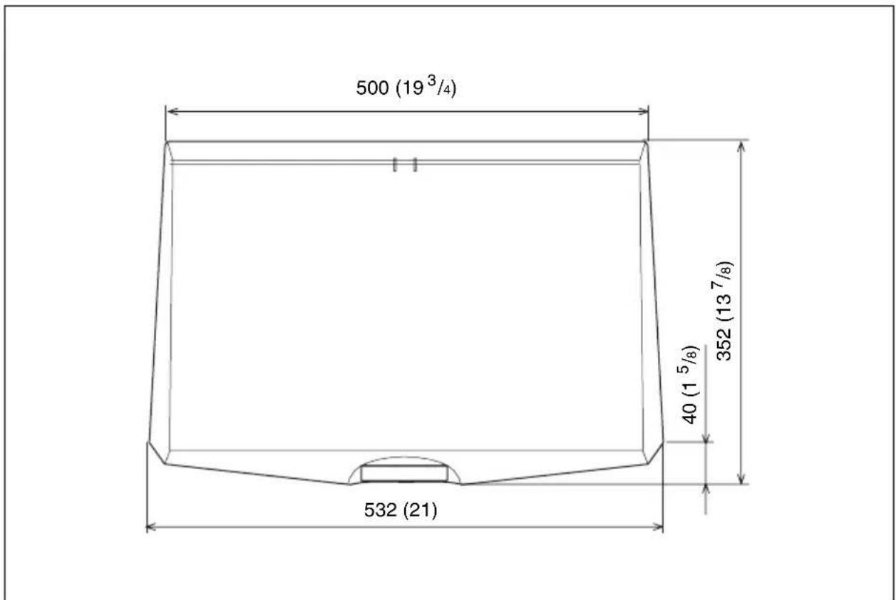
Unit: mm (inches)
Side

Unit: mm (inches)
Rear

Bottom

Unit: mm (inches)
Index
A
Adjust Signal APA ....32 Phase ....32 Pitch ....32 Shift ....32
Adjusting memory of the settings ....28
Air filter 44
Aspect 16:9 ....31 4:3 ....31 Full ....31 Full 1 ....31 Full 2 ....31 Normal ....31 Zoom ....31
Auto Input Search ....36
B
Background .....36 Batteries .....15 Black Level Adj. .....30 Blanking .....39 Brightness .....29
C
Color ....29 Color System ....35 Color Temp. ....29 Connecting a computer ....17 Connecting a VCR ....19 Contrast ....29
D
DDE ....30 Direct Power On ....39
F
fH 40 fV 40
G
Gamma Mode ....30
H
front remote control detector 10
location and function of controls ..... 14
rear remote control detector 11
Reset 29
resetting an item 28
s
Screen size 16,49
Security Lock 37
Sharpness 29
Smart APA 36
Specifications 49
Standby Mode ....34
Status ....34
Supplied accessories 51
T
Troubleshooting 45
V
V Center 32
V Keystone 38
Vertical Size 32
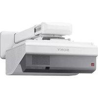

- WARNING
- IMPORTANT
- FOR KUNDENE I NORGE
- FOR THE CUSTOMERS IN THE USA
- FOR THE STATE OF CALIFORNIA, USA ONLY
- FOR THE CUSTOMERS IN CANADA
- FOR THE CUSTOMERS IN EUROPE, AUSTRALIA AND NEW ZEALAND
- FOR THE CUSTOMERS IN EUROPE
- FOR SAFETY
- FOR THE CUSTOMERS IN TAIWAN ONLY
- TABLE OF CONTENTS
- OVERVIEW
- PROJECTING THE PICTURE
- CONVENIENT FUNCTIONS
- ADJUSTMENTS AND SETTINGS USING A MENU
- MAINTENANCE
- OTHERS
- PRECAUTIONS
- ON SAFETY
- ON ILLUMINATION
- ON PREVENTING INTERNAL HEAT BUILD-UP
- ON CLEANING
- ON REPACKING
- ON LCD PROJECTOR
- NOTES ON INSTALLATION AND USAGE
- UNSUITABLE INSTALLATION
- POORLY VENTILATED
- HIGHLY HEATED AND HUMID
- SUBJECT TO DIRECT COOL OR WARM AIR FROM AN AIR-CONDITIONER
- NEAR A HEAT OR SMOKE SENSOR
- VERY DUSTY, EXTREMELY SMOKY
- USAGE IN HIGH ALTITUDE
- NOTE ON THE SCREEN
- UNSUITABLE CONDITIONS
- DO NOT TOPPLE THE UNIT
- DO NOT TILT RIGHT/LEFT
- DO NOT BLOCK THE VENTILATION HOLES
- DO NOT PLACE A BLOCKING OBJECT JUST IN FRONT OF THE LENS
- ABOUT THE SUPPLIED MANUALS
- MANUALS
- SAFETY REGULATIONS (SEPARATELY PRINTED MANUAL)
- QUICK REFERENCE MANUAL (SEPARATELY PRINTED MANUAL)
- OPERATING INSTRUCTIONS (ON THE CD-ROM) (THIS MANUAL)
- OPERATING INSTRUCTIONS FOR NETWORK (ON THE CD-ROM)
- INSTALLATION MANUAL FOR DEALERS (ON THE CD-ROM)
- NOTE
- SOFTWARE (ON THE CD-ROM)
- PROJECTOR STATION FOR AIR SHOT VERSION 2 (VERSION 2.XX) (JAPANESE AND ENGLISH ONLY)
- FEATURES
- HIGH BRIGHTNESS AND HIGH PICTURE PERFORMANCE
- HIGH BRIGHTNESS
- HIGH RESOLUTION
- HIGH PICTURE PERFORMANCE
- CONVENIENT AND FLEXIBLE SETUP
- POWER ZOOM/POWER FOCUS AND HORIZONTAL/VERTICAL LENS SHIFT FUNCTION
- CENTER POSITIONED LENS
- TILT INSTALLATION (AT FRONT AND REAR)
- DIRECT POWER ON/POWER OFF FUNCTION
- ID FUNCTION
- SIMPLE MAINTENANCE
- SYSTEM EXPANDABILITY USING A NETWORK
- MULTI SCAN COMPATIBILITY
- HDMI AND 5BNC CONNECTORS
- ACCEPTS VARIOUS INPUT SIGNALS
- NETWORK PRESENTATION
- OTHER CONVENIENT FUNCTIONS
- ABOUT TRADEMARKS
- LOCATION AND FUNCTION OF CONTROLS
- ⑥ AIR FILTER COVERS
- ⑦REAR REMOTE CONTROL DETECTOR
- ⑧CONNECTOR PANEL
- ⑨SECURITY LOCK
- 10CONTROL PANEL
- ⑪SPEAKERS
- ⑫VENTILATION HOLES (EXHAUST)
- ⑬VENTILATION HOLES (INTAKE)
- NOTES
- CONTROL PANEL
- ①LAMP/COVER INDICATORS
- ②ON/STANDBY INDICATOR
- ③SHIFT KEY
- 4ZOOM KEY
- ⑤FOCUS KEY
- ⑥MENU KEY
- ⑦ I/⏻ (ON/STANDBY) KEY
- ⑧INPUT KEY
- ⑨ ENTER/▲/▼/◄/► (ARROW) KEYS
- ①VIDEO IN (VIDEO INPUT)
- AUDIO INPUT L (MONO)/R (PHONO TYPE)
- ②/③ INPUT A/INPUT B
- ANALOG RGB CONNECTOR (HD D-SUB 15-PIN, FEMALE)
- AUDIO JACK (STEREO MINIJACK)
- ④ OUTPUT
- MONITOR CONNECTOR (HD D-SUB 15-PIN, FEMALE)
- ⑤ REMOTE
- RS-232C CONNECTOR (D-SUB 9-PIN, FEMALE)
- ⑥ AC IN SOCKET
- ⑦CONTROL S IN/PLUG IN POWER (DC 5V OUTPUT) JACK (STEREO MINIJACK)
- 8 INPUT C
- ANALOG RGB/COMPONENT CONNECTORS (R/R-Y/P R , G/Y, B/B-Y/P B , HD, VD) (BNC TYPE)
- AUDIO (STEREO MINIJACK)
- ⑨ INPUT D
- DIGITAL RGB/COMPONENT CONNECTOR (HDMI) (ACCEPTS HDCP)
- 10 INPUT E
- NETWORK CONNECTOR (RJ-45)
- CAUTION
- REMOTE COMMANDER
- 13MUTING KEYS
- 14D ZOOM (DIGITAL ZOOM) +/- KEY
- 15ZOOM +/- KEYS
- 16 FOCUS +/- KEYS
- ⑰SHIFT +/- KEYS
- 18 ↑/↓/←/→ KEYS (ARROW)
- 19MENU KEY
- 20 COMMAND ON/OFF SWITCH
- ⑳INFRARED TRANSMITTER
- TO INSTALL BATTERIES
- 2 REPLACE THE LID
- NOTES ON REMOTE COMMANDER OPERATION
- INSTALLING THE PROJECTOR
- VPL-FE40/FX40/FX41
- VPL-FW41
- CONNECTING THE PROJECTOR
- WHEN YOU CONNECT THE PROJECTOR, MAKE SURE TO
- CONNECTING A COMPUTER
- TO ATTACH THE HDMI CABLE
- CONNECTING A VCR
- TO CONNECT TO A VIDEO OR S VIDEO OUTPUT CONNECTOR
- TO CONNECT TO A VIDEO GBR/COMPONENT OUTPUT CONNECTOR
- PROJECTING
- TO ADJUST THE TILT OF THE INSTALLATION SURFACE
- TURNING OFF THE POWER
- 1 PRESS THE I/⏻ KEY
- 2 PRESS THE I/⏻ KEY AGAIN
- 3 UNPLUG THE AC POWER CORD FROM THE WALL OUTLET AFTER THE FAN STOPS RUNNING AND THE ON/STANDBY INDICATOR LIGHTS IN RED. (EXCEPT WHEN USING THE DIRECT POWER ON/OFF FUNCTION AND THE OFF & GO FUNCTION.)
- WHEN YOU CANNOT CONFIRM THE ON-SCREEN MESSAGE
- SELECTING THE MENU LANGUAGE
- TO CLEAR THE MENU
- SECURITY LOCK
- TO USE THE SECURITY LOCK
- SECURITY CERTIFICATION
- TO CANCEL THE SECURITY LOCK
- OTHER FUNCTIONS
- DIRECT POWER ON/OFF FUNCTION
- OFF & GO FUNCTION
- EFFECTIVE TOOLS FOR YOUR PRESENTATION
- TO FREEZE THE IMAGE PROJECTED (FREEZE FUNCTION)
- CONTROLLING THE COMPUTER USING A PRESENTATION TOOL, RM-PJPK1 (NOT SUPPLIED) (WHEN USING THE NETWORK PRESENTATION FUNCTION)
- USING A MENU
- DISPLAY ITEMS
- INPUT SIGNAL INDICATOR
- NEXT MENU WINDOW
- TO RESET ITEMS THAT HAVE BEEN ADJUSTED
- UNADJUSTABLE ITEMS
- STORAGE OF THE SETTINGS
- IF NO SIGNAL IS INPUT
- THE PICTURE MENU
- WHEN THE VIDEO SIGNAL IS INPUT WHEN THE SIGNAL IS INPUT FROM A COMPUTER
- THE SCREEN MENU
- ABOUT THE PRESET MEMORY NO
- THE SETUP MENU
- THE FUNCTION MENU
- THE INSTALLATION MENU
- THE INFORMATION MENU
- INPUT SIGNALS AND ADJUSTABLE/SETTING ITEMS
- SCREEN MENU
- REPLACING THE LAMP
- DISPOSAL OF THE USED LAMP
- CLEANING THE AIR FILTER
- TROUBLESHOOTING
- MESSAGES LIST
- WARNING MESSAGES
- CAUTION MESSAGES
- SPECIFICATIONS
- OPTICAL CHARACTERISTICS
- ELECTRICAL CHARACTERISTICS
- INPUT/OUTPUT
- GENERAL
- OPTIONAL ACCESSORIES
- PIN ASSIGNMENT
- INPUT A/B
- REMOTE
- PRESET MEMORY NO. AT THE INPUT SIGNAL
- ANALOG SIGNALS
- DIGITAL SIGNALS
- DIMENSIONS
- INDEX
- A
- B
- C
- D
- F
- G
- H
- S
- T
- V
Brand : SONY
Model : VPL-FX40L
Category : Projector