
SP-H800 - Projector SAMSUNG - Free user manual and instructions
Find the device manual for free SP-H800 SAMSUNG in PDF.


| Product Type | DLP Projector |
| Model | Samsung SP-H800 |
| Panel Resolution | 1280 x 720 (HD2+, DC3) |
| Lamp Type | 250W UHP |
| Lamp Life | 2000 hours |
| Brightness | 700 ANSI lumens |
| Contrast Ratio (Theatre Mode) | 3800:1 |
| Screen Size (Diagonal) | 30.385 - 300 inches |
| Projection Distance | 1.0 - 13.6 m |
| Keystone Correction | Vertical only |
| Lens Shift | Vertical (manual dial) |
| Zoom & Focus | Manual zoom and focus |
| Input Ports | DVI-D (HDCP), PC (15-pin D-Sub), Component 1 & 2, S-Video, Composite, RS-232C |
| Power Consumption | 350W |
| Power Supply | AC 100-240V, 50/60Hz |
| Dimensions (W x D x H) | 384 x 425 x 177 mm |
| Weight | 9.0 kg (19.8 lb) |
| Noise Level (Theatre Mode) | 28 dB |
| Lamp Replacement | User-replaceable (LAMP-MERCURY-Philips) |
| Maintenance | Clean lens with dry soft cloth; avoid solvents |
| Safety Precautions | Do not stare into lens; avoid hot exhaust; unplug before lamp replacement |
Frequently Asked Questions - SP-H800 SAMSUNG
User questions about SP-H800 SAMSUNG
0 question about this device. Answer the ones you know or ask your own.
Ask a new question about this device
Download the instructions for your Projector in PDF format for free! Find your manual SP-H800 - SAMSUNG and take your electronic device back in hand. On this page are published all the documents necessary for the use of your device. SP-H800 by SAMSUNG.
USER MANUAL SP-H800 SAMSUNG
Correct Disposal of This Product
(Waste Electrical & Electronic Equipment)
(Applicable in the European Union and other European countries with separate collection systems)
This marking shown on the product or its literature indicates that it should not be disposed with other household wastes at the end of its working life. To prevent possible harm to the environment or human health from uncontrolled waste disposal, please separate this from other types of wastes and recycle it responsibly to promote the sustainable reuse of material resources. Household users should contact either the retailer where they purchased this product, or their local government office, for details of where and how they can take this item for environmentally safe recycling.
Responsibly to promote the sustainable reuse of material resources. Household users should contact either the retailer where they purchased this product, or their local government office, for details of where and how they can take this item for environmentally safe recycling.
Business users should contact their supplier and check the terms and conditions of the purchase contract. This product should not be mixed with other commercial wastes for disposal.
OWNER'S
DLP PROJECTOR


Owner's Instructions SP-H800
Table of Contents
Preparation
Features and Design......4
Caution on Lamp Use and Replacement......5
Projector and Accessories
Projector and Accessories
Front/Upper Side and Accessories......8
Rear Side and Cables 10
Remote Control Buttons 11
Operating the Remote Control....12
Installation and Basic Adjustments
Installation 14
Turning ON/OFF 15
Zooming and Focus Adjustment......16
Leveling with Adjustable Feet 17
Using the Lens Shift Dial....18
Screen Size and Projection Distance....19
Connections and Source Setup
Before Connections ......22
Connecting to Video Equipment
Connecting to VCR/Camcorder/Cable Box .....23
Connecting to DVD 24
Connecting to the Digital TV Receiver....25
Setting up the External Input Source ......26
Naming the External Connections .....27
Picture Adjustment
Selecting Picture Mode ....30
Custom Settings of the Picture....31
Changing the Color Standard 32
Selecting and Adjusting Color Temperature ....33
Gamma Correction 34
Saving Custom Picture Settings ....35
Setting up DNle 36
Selecting Picture Size....37
Screen Position Adjustment 39
Selecting Noise Reduction ....40
Color Control......41
Film Mode 42
Overscan 43
Setting the Black Level 44
Still Picture 45
Setup
Flipping/Reversing the Projected Image .....48
Light Setting 49
Correcting Vertical Keystone ....50
Test Patterns ....51
Restoring the Factory Default Settings....52
Information....53
Setting the LED 54
Menu Option
Setting the Language....56
Setting the Menu Position....57
Setting the Menu Translucency....58
Setting the Menu Display Time....59
Selecting the Quick Menu ....60
Connecting to PC
Before Connecting to PC 62
Setting up the PC Environment....63
Connecting to PC....64
Automatic Picture Adjustment ....66
Frequency Adjustment ....67
Fine Tuning with the Phase Adjustment .....68
Zooming the Screen 69
Reset the PC 70
Troubleshooting
Before Contacting Service Personnel....72
Other Information
Storage and Maintenance ....76
Purchasing Optional Parts....77
Glossary 78
Structure of Screen Menu 80
Lamp Replacement 83
RS-232C Connection and Control 84
Specifications 86
Remote Control Specifications ....87
Features and Design
Optical engine adopting advanced DLP technology
■ The DLP HD2+, DC3 DMD panel of 1280x720 pixels resolution has been adopted. ■ 5X-speed color wheel designed to reduce digital artifacts ■ 250W Lamp designed to improve luminance
Vivid colors
■ Quality picture tuning focused on improving color - this unit aims at realizing color coordinates that meet broadcasting standards on video production.
Minimized fan noise and light leakage
■ The airflow and fan installation structure are optimized to minimize fan noise and beam leakage.
Various Input Ports
■ Five types of input ports including a DVI-D (compatible with HDCP) port, two Component ports improve connection to external peripherals.
User adjustments
■ This unit allows adjustment of each input port. ■ The unit has a reference pattern that can be used for positioning and adjustment. ■ For the user's convenience in dark surroundings, a backlight for the remote control is provided.
Caution on Lamp Use and Replacement
Projector Lamp
■ The projector lamp is an expendable whose life time and performance is determined by the operating conditions such as the usage time and environment. The lamp needs to be replaced periodically before the life time ends so as to prevent a sudden degradation of performance or malfunction. ■ Free servicing will be offered within 90 days after purchasing of the product and within 300 hours of product use, if the problem is due to a defective lamp. ■ You can check the lamp use time by pressing the INFO button on the remote control.
Caution on Lamp Replacement
■ Unplug the power cord before replacing the lamp. ■ Inside of the projector is very hot. Cool off the projector for at least an hour after turning off. ■ Contact your dealer to purchase a lamp for replacement. (Ultra violets from the lamp can damage your eyes.) ■ Turn off the power of the lamp before replacement or repair. (Due to the high-pressure of the lamp, it is possible to explode.) ■ Take care when handling the lamp because any broken pieces of glass may harm you if the lamp breaks. For more detailed information about the procedures to use, refer to on page 83.
Caution on Lamp Use
■ This projector produces intense light. Do not stare light source directly. Take Care: The ultraviolet ray from the lamp may harm your eyesight. ■ Do not touch the exhaust vent during operation. It can be very hot. ■ Do not expose the unit to rain or moisture.

VISUAL REALISM
Preparation
Projector and Accessories 8
Installation and Basic Adjustments .....14
PROJECTOR AND ACCESSORIES
Front/Upper Side and Accessories
Front/Upper Side

11 Indicators
- TEMP (Red LED)
- LAMP (Blue LED)
- STAND BY (Blue LED)
Refer to page 9 for details.
2 Remote Control Signal Receiver 3 Focus Ring
Used for Focus Adjustment.
4 Lens 5 Adjustable Feet
You can adjust the screen position by moving up and down the adjustable feet.
6 Zoom Knob
Used to enlarge or reduce image size.
77 MENU
Use this button to enter or exit a menu or to move forward in a menu.
8 POWER
Used to turn the projector on or off.
9 SOURCE
Used to select input signals from the external sources.
10 Select and Move Button
Use this button to move to or select an item within a menu.
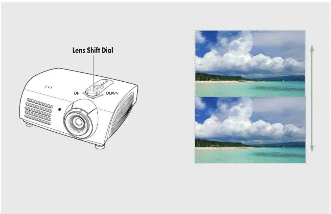
1 Lens Adjustment Dial
You can adjust screen images up and down within the lens range.
Accessories
Remote Control/2 Batteries
Power Cable
Owner's Instructions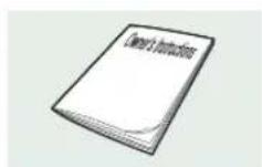
Indicator Information
● : Turned on ○Blinks : Turned off
| STANDBYLAMPTEMP | Information | ||
| ○ | ○ | ● | If you press the POWER button on the remote control or projector, the screen appears within 30 seconds. |
| ○ | ● | ● | The projector is in normal operating condition. |
| ○ | ○ | ● | This state appears when the projector is preparing an operation after the POWER button on the projector or the remote control has been pressed. |
| ○ | ○ | ○ | The POWER button is pressed to turn off the projector, and the cooling system is in operation to cool off inside of the projector. (Lasts for about 1 minute and 30 seconds) |
| ○ | ○ | ○ | Refer to measure 1 below if the cooling fan inside the projector is not in normal operation condition. |
| ○ | ○ | ○ | Refer to measure 2 below if the lamp cover protecting the lamp unit is not closed properly. |
| ○ | ○ | ○ | Power is turned off automatically when temperature inside of the projector goes beyond the control limit. Refer to measure 3. |
| ○ | ○ | ○ | Refer to measure 4 below if the life span of the lamp is running out or a problem with the lamp is detected. |
Clearing Indicator Problems
| Classification | State Measures | |
| Measure 1 | When the cooling fan system is not in normal operating condition. | If the symptom remains even after disconnecting and then reconnecting the power cord and turning the projector on again, contact your product provider or our service center. |
| Measure 2 | When the lamp cover protecting the lamp unit is not properly closed or the sensor system is not in normal operating condition. | Check the screw on the bottom side of the projector. If you do not find any problem, contact a dealer or service personnel near you. |
| Measure 3 | When temperature inside of the projector becomes too high. | Adjust the position of the projector following the installation instructions of this manual and cool off the projector before restarting it. If the problem does not disappear, contact a dealer or service personnel near you. |
| Measure 4 | The lamp is malfunctioning after abnormal power off or restarting right after turning off the projector. | Turn the power off, wait for a sufficient amount of cooling time and then turn the power on for operations. |
| When brightness of the picture screen degrades or image deterioration is found. | Check how long the lamp has been used on Information and contact a dealer or service personnel near you for lamp replacement. |

NOTE
This Projector uses a cooling fan system to keep the unit from overheating.
Operation of the cooling fan may cause noise, which does not affect the product performance.
No exchange or refund for the noise concern.
PROJECTOR AND ACCESSORIES
Rear Side and Cables
Rear Side

1 Remote Control Signal Receiver 2 S-VIDEO Input port 3 COMPOSITE Input ports
44 RS-232C port 5 DVI Input port 6 PC Input port
7 AC Power Input 8 Power Switch 9 Component Input port
Cables
Power Cord
Connected to the wall outlet 7.

Video Cable
(Optional Parts)
Connected to the connection port 3.

S-Video Cable
(Optional Parts)
Connected to the connection port 2.

Component Cable (Optional Parts)
Connected to the connection port 9.

PC Video Cable (Optional Parts)
Connected to the connection port 6.

DVI-D Cable
(Optional Parts)
Connected to the connection port 5.

PROJECTOR AND ACCESSORIES
Remote Control Buttons

11 ON Used to turn on the projector.
22 COMP.1 (Pages 24~27) Used to switch to COMPONENT 1 Mode.
3 COMP.2 (Pages 24~27) Used to switch to COMPONENT 2 Mode.
4 S-VIDEO (Pages 23, 26) Used to switch to S-VIDEO Mode.
5 P.SIZE (Page 37) Used to adjust the size of picture screen.
64 P.MODE (Page 30) Used to select Picture Mode.
7 STILL (Page 45) Used to see still images.
8 V. KEYSTONE (Page 50) You can use this function for trapezoidal adjustment of the image.
9 QUICK (Page 60) Used to quickly select the previous menu.
110 MENU Used to display Menu Screen.
111 ▲▼◀▶(Move) / (Select) Used to move to or select each menu item.
112 OFF Used to turn off the projector.
113 LIGHT (Page 13) Used to operate remote control in dark room.
114 PC (Pages 25, 64, 66~70) Used to switch to PC Mode.
115 DVI (Page 25, 64) Used to switch to DVI Mode.
116 COMPOSITE (Pages 23, 26) Used to switch to COMPOSITE Mode.
117 CUSTOM (Page 31) Used to select Picture User Adjust Mode.
118 INSTALL (Page 48) Used to flip or reverse the projected image.
119 INFO (Page 53) Used to check source signals, picture setup, PC screen adjustment and lamp lifespan.
220 EXIT Used to make Menu Screen disappear.
PROJECTOR AND ACCESSORIES
Operating the Remote Control
Operating Move/Select Button


Move Menu Item (Up)

Move Menu Item (Down)

Setting the Adjustment (right), or move to lower item.

Setting the Adjustment (left), or move to upper item

Select the current setting
Inserting Batteries into Remote Control
- Press on the part of the lid to remove it.
- Insert two AAA-sized 1.5V batteries by matching the + and - terminals.
- Close the lid.

Allowable range and angle for receiving the remote control signal
The remote control is effective within a 30-degree angle and at a distance of 7 to 10 meters from the projector.

- Keep used batteries away from children and dispose of them properly. Do not use new and used batteries together. Replace both batteries at the same time. Remove batteries when the projector is not used for long periods of time.

Using the Remote Control in a Dark Place (LIGHT)
Press the LIGHT button on the remote control for five seconds. The remote control buttons will light up for about 5 seconds and then turn off automatically.

INSTALLATION AND BASIC ADJUSTMENTS
Installation
To Install the Projector
Install the projector so that the projection is perpendicular to the screen.
NOTE
Center the lens on the screen. If the projector is not positioned perpendicular to the screen, the image may appear trapezoidal. Do not install the screen in a bright place, as it makes it harder to see the screen. Darken the room when installing the projector in a bright place.

Installing the Projector Behind the Screen
Install a translucent screen to place the projector behind the screen. The translucent screen will show a horizontally flipped image. Rotate the image (projected from the projector) horizontally. (See page 48)

Installing Projector in Front of the Screen
Install the projector at the viewers' side.
NOTE
■ The projector may be installed on the ceiling in front / back side of the screen. ■ When installing the projector on the ceiling, contact your dealer.

INSTALLATION AND BASIC ADJUSTMENTS
Turning ON/OFF
Turning On Projector
- Plug the power cord into the power terminal on the rear side of the projector.
- Press and push the power switch on the rear side of the projector toward " —".
- Press the POWER button of the projector or the ON button of the remote control.
- A picture will be displayed on the screen in approximately 30 seconds.
1
2
3
NOTE
When you turn off the projector, the cooling fan stops within 1 minute and 30 seconds. When the cooling fan stops, push the power switch toward "O" and unplug the power cord.
Turning the power OFF
- Press the [POWER] button on the projector or the [OFF] button on the remote control.
- Select the [OK] button displayed on the screen.
- Do not unplug the power cord from the wall outlet, and do not press the side of the power switch at the back of the projector during the cooling time (approximately one and a half minutes). Insufficient cooling may reduce the life time of the product. During the cooling time, the [LAMP] operating LED on the main body blinks.
- When the cooling operation is successfully completed, the [LAMP] operating LED on the main body is turned off and the [STAND BY] operating LED is turned on. Press the side of the power switch at the back of the projector to minimize standby power consumption.
1
2
3
INSTALLATION AND BASIC ADJUSTMENTS
Zoom and Focus Adjustment
Using the Zoom Knob and the Focus Ring
- You can adjust the size of image within zoom range by manipulating the Zoom Knob.
- Focus the picture on the screen using the Focus Ring.


NOTE
Focus may appear dim if the projector is installed at a shorter than recommended distance. (Page 19)
INSTALLATION AND BASIC ADJUSTMENTS
Leveling with Adjustable Feet
For level placing of the projector, adjust the Adjustable Feet of the projector.


NOTE
■ You may adjust the level of the projector up to 5 degrees. ■ Depending on the position of the projector, Keystone distortion of image may appear. (Page 50)
INSTALLATION AND BASIC ADJUSTMENTS
Using the Lens Shift Dial
Using the Lens Shift Dial
Move the picture projected on the screen up and down within the lens range by turning the Lens Shift Dial on the top side of the projector with your fingers.
INSTALLATION AND BASIC ADJUSTMENTS
Screen Size and Projection Distance
Install the projector on a flat, even surface and level the projector using the adjustable feet to realize optimal picture quality. If images are not clear, adjust them using the Zoom Knob or Focus Ring, or move the projector forward and backward.
| Diagonal Image Size (inch) | Screen Size (16:9) | Throw Distance (Z) | Distance from Lens Center to Image Bottom (Z':cm/inch) | ||
| Horizontal (X:cm/inch) | Vertical (Y:cm/inch) | Min (m/ft) | Max (m/ft) | ||
| 300 | 666.3 | 374.6 | 10.5 | 13.6 | 31.2 |
| 250 | 555.3 | 312.2 | 8.6 | 11.4 | 26.0 |
| 200 | 444.2 | 249.7 | 6.9 | 9.1 | 20.8 |
| 190 | 422.0 | 237.2 | 6.6 | 8.6 | 19.8 |
| 180 | 399.8 | 224.7 | 6.2 | 8.2 | 18.7 |
| 170 | 377.6 | 212.3 | 5.9 | 7.7 | 17.7 |
| 160 | 355.4 | 199.8 | 5.5 | 7.3 | 16.6 |
| 150 | 333.2 | 187.3 | 5.2 | 6.8 | 15.6 |
| 140 | 311.0 | 174.8 | 4.8 | 6.4 | 14.6 |
| 130 | 288.7 | 162.3 | 4.5 | 5.9 | 13.5 |
| 120 | 266.5 | 149.8 | 4.1 | 5.5 | 12.5 |
| 110 | 244.3 | 137.3 | 3.8 | 5.0 | 11.4 |
| 100 | 222.1 | 124.9 | 3.5 | 4.5 | 10.4 |
| 90 | 199.9 | 112.4 | 3.1 | 4.1 | 9.4 |
| 80 | 177.7 | 99.9 | 2.8 | 3.6 | 8.3 |
| 70 | 155.5 | 87.4 | 2.4 | 3.2 | 7.3 |
| 60 | 133.3 | 74.9 | 2.1 | 2.7 | 6.2 |
| 50 | 111.1 | 62.4 | 1.7 | 2.3 | 5.2 |
| 43 | 95.5 | 53.7 | 1.5 | 1.9 | 4.5 |
| 40 | 88.8 | 49.9 | 1.4 | 1.8 | 4.2 |
| 33 | 73.3 | 41.2 | 1.1 | 1.5 | 3.4 |
| 30.385 | 67.5 | 37.9 | 1.0 | 1.4 | 3.2 |
NOTE This projector is designed to show images optimally on a 80 to 150 inch sized screen.


NOTE
■ Z: Throw Distance
■ Z': Distance from Lens Center to Image Bottom

VISUAL REALISM
Connections and Source Setup
Before Connections ......22
Connecting to Video Equipment ......23
Setting up the External Input Source .....26
Naming the External Connections .....27
Before Connections
Check the following before connecting the projector to other devices.
Check the following Before Connecting
- Refer to the manual of the device the projector is connected to. The number and position of ports may differ depending on the type of device.
- Do not connect power until all connections are completed. If you try to connect power while connecting cables, it may result in damage to the projector.
- Check the type of ports the projector is connected to.
- This product receives video signals from an external device and displays the video on a screen. For audio signals, an additional audio system is required.
Refer to "Rear Side and Cables" on page 10 for cables used for connection.
CONNECTING TO VIDEO EQUIPMENT
Connecting to VCR/Camcorder/Cable Box

1
Connect the COMPOSITE (yellow) input port of the projector to the VIDEO (yellow) OUT port of the video equipment using the video cable.
If the video equipment has an S-VIDEO OUT port, connect it to the S-VIDEO input port of the projector.
■ Using the S-VIDEO connection provides higher visual quality.
2
When finished connecting the devices, connect the power of the projector and the VCR.
Viewing the picture

1 Turn on the projector and press the COMPOSITE button to select Composite.
2 Connect the projector and the video equipment via an S-Video cable and press the S-VIDEO button to select S-Video.
■ When Composite Mode is not available, check that the video cables are in place.
NOTE
■ Check that the projector and the video equipment are turned off before connecting cables. ■ This projector does not support sound. (A separate audio system is needed for sound.) ■ This product does not support the PAL-N broadcasting type.
Composite
CONNECTING TO VIDEO EQUIPMENT
Connecting to DVD
Rear side of Projector
1
Connect the COMPONENT 1
(Y/Pb/Pr) or COMPONENT 2
(Y/Pb/Pr) input port at the back of the projector to the Component port at the back of the DVD with the component cable.
2
When finishing connecting the devices, connect the power of the projector and the DVD.
Viewing the picture

1 Turn on the projector and press the COMP.1 button to select Component1.
2 Press the COMP.2 button to select Component2 if COMPONENT2 is connected.
■ When Component Mode is not available, check that the component cables are in place.
NOTE
Component Ports are marked as (Y, PB, PR), (Y, B-Y, R-Y) or (Y, Cb, Cr) depending on the manufacturer.
Component1
CONNECTING TO VIDEO EQUIPMENT
Connecting to the Digital TV Receiver

1 Connect antenna cable to antenna signal input terminal of the receiver.
3 After finishing connecting the devices, connect the power of the projector and the DTV receiver.
2 Connect the back of the digital broadcast receiver with the component cable.
If the digital broadcast receiver provides a DVI or PC output port, you can connect a digital broadcast receiver using the [DVI] or [PC] input port of the projector.
Viewing the picture
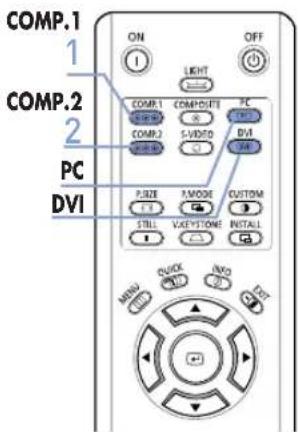
1 Turn on the projector and press the COMP.1 button to select Component1.
2 Press the COMP.2 button to select Component2 if COMPONENT2 is connected. If the receiver is connected to DVI or PC port, press the DVI or PC button to select DVI or PC respectively.
■ When Component Mode is not available, check that the component cables are in place.
Component1
DVI
Setting up the External Input Source
You can select a device connected to the projector to display.


Press the desired source button (COMP.1/COMP.2/S-VIDEO/COMPOSITE/PC/DVI).
Pressing a button switches to the respective mode. You cannot switch to the mode if the projector is not connected to the respective device.


1 Press the MENU button. The main menu is displayed.

2 Press the button to select Input. The Input menu is displayed.

3 Press the button to select Source List. The Source List menu is displayed.

4 Press the ▲ or ▼ button to move to the desired input mode, then press the button. The source input you chose is displayed. If the input mode is not selected, check that cables are in place.

5 Press the EXIT button to exit the settings.


Naming the External Connections
You can edit the names of devices connected to the projector.
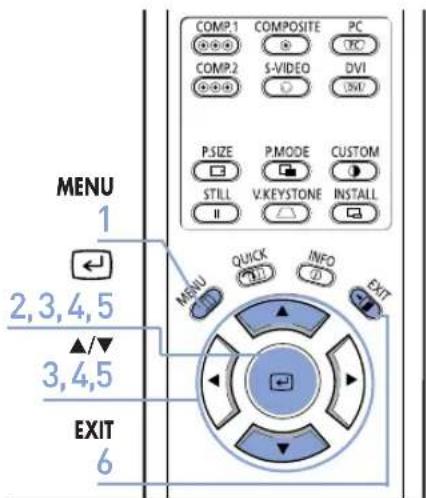

1 Press the MENU button. The main menu is displayed.

2 Press the button to select Input. The Input menu is displayed.

3 Press the ▲ or ▼ button to move to Edit Name, then press the button. The Edit Name menu is displayed.

4 Press the ▲ or ▼ button to move to the edited input mode, then press the button.

5 Press the ▲ or ▼ button to move to the desired device, then press the button. Setup is switched to the selected device.
6 Press the EXIT button to exit the settings.


Picture Adjustment
Selecting Picture Mode ....30
Custom Settings of the Picture....31
Changing the Color Standard ....32
Selecting and Adjusting Color Temperature 33
Gamma Correction 34
Saving Custom Picture Settings ....35
Setting up DNle 36
Selecting Picture Size....37
Screen Position Adjustment ....39
Selecting Noise Reduction......40
Color Control......41
Film Mode 42
Overscan 43
Setting the Black Level 44
Still Picture 45
Selecting Picture Mode


Press the P.MODE button.
Each press of the button switches the picture mode to Dynamic, Standard, Movie1, Movie2, User1, User2, User3, and Custom.


1 Press the MENU button. The main menu is displayed.

2 Press the ▲ or ▼ button to move to Picture. The Picture menu is displayed.

3 Press the button. The Picture Mode options will be displayed.

4 Press the ▲ or ▼ button to move to the desired mode, then press the button. When pressing the ▲ or ▼ buttons, the Picture Mode changes sequentially: Dynamic - Standard - Movie 1 - Movie 2 - User 1 - User 2 - User 3 - Custom.

5 Press the EXIT button to exit the settings.
Settings for Each Picture Mode
| Picture Mode Temperature | Color | Gamma |
| Dynamic 9 | 300K Graphic: | Gamma mode that matches a PC screen. |
| Standard 8 | 000K Video: | Gamma mode normal that matches a TV screen. |
| Movie1 65 | 00K | Film: Film mode gamma. |
| Movie2 55 | 00K |


NOTE
You can save your screen settings in User 1, User 2, and User 3 according to your needs.
▶ See page 35.
Custom Settings of the Picture
You can adjust Contrast, Brightness, Sharpness, Color and Tint of the picture as desired.


Press the CUSTOM button.
The Custom Picture menu is displayed.
Refer to number 4 below to make adjustments.


1 Press the MENU button.
The main menu is displayed.
2 Press the ▲ or ▼ button to move to Picture.
The Picture menu is displayed.

3 Select Picture, then press the button.
The Custom Picture menu is displayed.

4 Then press the button. Press the button to adjust the selected item.
A separate adjustment window appears for making the adjustment.

5 Press the EXIT button to exit the settings.

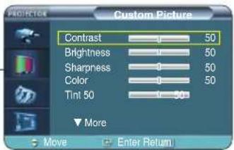

Custom Picture Menu
| Contrast Used to adjust the contrast between the object and the background. |
| Brightness Used to adjust brightness of the entire picture. |
| Sharpness Used to adjust the outlines of the object sharper or less sharp. |
| Color Used to adjust color lighter or deeper. |
| Tint Used to obtain more natural color of objects using Green or Red enhancement. |

■ You can only adjust color in S-Video and Composite modes. ■ You cannot adjust the sharpness in Component1, 2(720p), PC and DVI modes.
Changing the Color Standard
You may adjust the color standard to suit the color standard of the input signal.

| SMPTE_C | Standardized for Video Equipment by the Society of Motion Picture and Television Engineers | NTSC |
| HD High Definition, 1125 scan lines, standard ATSC definition TV submitted to the ITU-R by U.S., Japan and Canada, in 1986. | ||
| EBU Regulations and standards for European PAL, Broadcasting Production and Technology, standardized by the European Broadcasting Union. | SECAM | |

1 Press the MENU button. The main menu is displayed.
2 Press the ▲ or ▼ button to move to Picture, then press the [button]. The Picture menu is displayed.

3 Press the ▲ or ▼ button to move to Custom Picture, then press the button. The Custom Picture menu is displayed.

4 Press the ▲ or ▼ button to move to Color Standard, then press the 📄 button. The Color Standard options will be displayed.

5 Press the ◀ or ▶ button to move to desired item, then press the button.


6 Press the EXIT button to exit the settings.
Selecting and Adjusting Color Temperature
You can change tint of the entire screen to suit your needs.

Color Temperature Menu
| 5500K | Used to deliver optimal image quality for black-and-white films. Color temperature of the picture mode of Movie2 is set to 5500K. |
| 6500K | This temperature is used for the most video productions. It is set as Movie1 when it is manufactured, and may deliver the most precise tint. |
| 8000K | The color temperature appropriate to quite bright places and saved in Dynamic Picture Mode. The sharpness and brightness are emphasized. |
| 9300K | The color temperature appropriate to very bright places such as a shop. |

Gamma Correction
An image compensation function that controls the settings according to the video properties.


1 Press the MENU button. The main menu is displayed.

2 Press the ▲ or ▼ button to move to Picture, then press the [button]. The Picture menu is displayed.

3 Press the ▲ or ▼ button to move to Custom Picture, then press the button. The Custom Picture menu is displayed.

4 Press the ▲ or ▼ button to move to Gamma, then press the button. The Gamma is selected.

5 Press the ▲ or ▼ button to move to desired mode, then press the button. Setup is switched to the selected mode.

6 Press the EXIT button to exit the settings.


Gamma Mode
| Graphic | The Gamma mode that matches a PC screen. |
| Video | The Gamma mode normal that matches a TV screen. |
| Film | Film mode gamma. |
Saving Custom Picture Settings
Used to save custom picture (Contrast, Brightness, Sharpness, Color, Tint, Color Temperature and Gamma) settings.


1 Press the MENU button. The main menu is displayed.

2 Press the ▲ or ▼ button to move to Picture, then press the button. The Picture menu is displayed.

3 Press the ▲ or ▼ button to move to Custom Picture, then press the button. The Custom Picture menu is displayed.

4 Press the ▲ or ▼ button to move to Save, then press the button. The Save menu is displayed.

5 Press the ▲ or ▼ button to move to desired mode, then press the button.
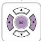
6 Press the ◀ or ▶ button to move to OK, then press the 📊 button. Setup is switched to the selected mode.

7 Press the EXIT button to exit the settings.


NOTE
The User1, User2 and User3 modes are saved differently according to external input sources (Component1/Component2/S-Video/Composite/PC/DVI).
Setting up DNle
DNle (Digital Natural Image engine) is an image enhancing function developed by Samsung Electronics. It enables users to enjoy brighter, sharper and more dynamic pictures.


1 Press the MENU button. The main menu is displayed.

2 Press the ▲ or ▼ button to move to Picture, then press the 📣 button. The Picture menu is displayed.

3 Press the ▲ or ▼ button to move to DNle, then press the button. The DNle options will be displayed.

4 Press the ▲ or ▼ button to move to On, then press the button. Setup is switched to the selected mode.

5 Press the EXIT button to exit the settings.


DNIe Mode
Off DNle Mode Off Demo DNle On/Off Picture Comparison Mode On The mode when the DNle function is enabled.
Selecting Picture Size


Press the P.SIZE button.
When pressing the P.SIZE button, the screen size changes to Full - Zoom 1 - Zoom 2 - 4 : 3 sequentially.

![graph TD A["MENU"] --> B["Arrow to Top Left"] B --> C["Arrow to Middle Right"] C --> D["Arrow to Bottom Right"] D --> E["Arrow to Left Bottom"] E --> F["EXIT"]](/content/2026/05/1127518/images/a1f06e7f924380143478ec40a774765796ec144bcd9201fe5616ea27faac6972.jpg)
1 Press the MENU button.
The main menu is displayed.
2 Press the ▲ or ▼ button to move to Picture, then press the button.
The Picture menu is displayed.
3 Press the ▲ or ▼ button to move to Picture Size, then press the button.
The Picture Size is selected.
4 Press the ▲ or ▼ button to move to desired mode, then press the button.
Setup is switched to the selected mode.
5 Press the EXIT button to exit the settings.


Supported Picture Sizes
O : Supported Modes X : Unsupported Modes
| Input | Picture Size | |||||
| Source | Signal | Mode | Full | Zoom1 | Zoom2 | 4:3 |
| DVI | HD | 1080i | O | X | X | O |
| 720p | O | X | X | X | ||
| 576p | O | O | X | O | ||
| 480p | O | O | X | O | ||
| PC | 16:9 Mode | O | X | X | X | |
| 4:3 Mode | O | X | X | O | ||
| PC(D-Sub) | HD | 1080i | O | X | X | O |
| 720p | O | X | X | X | ||
| 576p | O | O | X | O | ||
| 480p | O | O | X | O | ||
| PC | 16:9 Mode | O | X | X | X | |
| 4:3 Mode | O | X | O | |||
| Component | HD | 1080i | O | X | X | O |
| 720p | O | X | X | O | ||
| 576p | O | O | X | O | ||
| 480p | O | O | X | O | ||
| SD | 576i | O | O | O | O | |
| 480i | O | O | O | O | ||
| Composite & S-Video | SD | 480i | O | O | O | O |

NOTE
Refer to page 62 for display modes supported.
Screen Position Adjustment
Adjust the screen position if the edges are not aligned.


1 Press the MENU button.
The main menu is displayed.

2 Press the ▲ or ▼ button to move to Picture, then press the button.
The Picture menu is displayed.

3 Press the ▲ or ▼ button to move to Position, then press the button.
The Position is displayed.

- Press the ⊥, V, V, 6.9 buttons to adjust the position.
The screen position is determined according to the selected screen position.

5 Press the EXIT button to exit the settings.


NOTE
■ The respective position information is set and stored automatically to the corresponding external input modes (Component 1, 2 / S-Video, Composite / PC).
■ In DVI mode, the screen position setting will not work.
Selecting Noise Reduction
When a dotted line is displayed or the screen trembles, you can view picture in better visual quality by enabling Noise Reduction.


1 Press the MENU button. The main menu is displayed.

2 Press the ▲ or ▼ button to move to Picture, then press the button. The Picture menu is displayed.
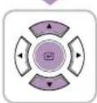
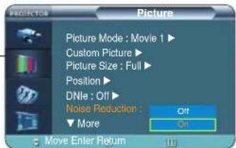
3 Press the ▲ or ▼ button to move to Noise Reduction, then press the button. The Noise Reduction options will be displayed.

4 Press the ▲ or ▼ button to move to On, then press the button. Noise Reduction is activated. If you select Off, Noise Reduction is disabled.

5 Press the EXIT button to exit the settings.

NOTE
You can only enable the Noise Reduction function in Composite, S-Video and Component1, 2(480i) modes.
Color Control
You can filter the color of the entire screen according to your taste.

![graph TD A["MENU"] --> B["Press the MENU button.<br>The main menu is displayed."] C["2"] --> D["Press the ▲ or ▼ button to move to Picture,<br>then press the button.<br>The Picture menu is displayed."] E["3"] --> F["Press the ▲ or ▼ button to move to Color Control, then press the button.<br>The Colo…](/content/2026/05/1127518/images/8943de1d2a365d3b90d0e06ce0ef3e017f5a7eb09441d7bbf134c1bec5098fc2.jpg)
Color Control Mode
| Off Shows the picture in the original color. | |
| Monochrome | Shows the picture in black and white color by filtering out all color signals. |
| Red Shows the picture in red by filtering out the green and blue color signals. | |
| Green Shows the picture in green by filtering out the red and blue color signals. | |
| Blue Shows the picture in blue by filtering out the red and green color signals. | |
Film Mode
Using this function, you can set the display mode optimized for playing movies when watching a movie. Film Mode provides optimal display settings for movies.
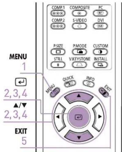

1 Press the MENU button. The main menu is displayed.

2 Press the ▲ or ▼ button to move to Picture, then press the button. The Picture menu is displayed.

3 Press the ▲ or ▼ button to move to Film Mode, then press the button. The Film Mode options will be displayed.

4 Press the ▲ or ▼ button to move to On, then press the button. Setup is switched to the selected mode.

5 Press the EXIT button to exit the settings.


NOTE
Film Mode is only supported for Composite, S-Video and Component (480i).
Overscan
Using this function, you can cut the edge of the picture when there is unnecessary information, images or noise on the edge of the picture.


1 Press the MENU button. The main menu is displayed.

2 Press the ▲ or ▼ button to move to Picture, then press the button. The Picture menu is displayed.

3 Press the ▲ or ▼ button to move to Overscan, then press the button. The Overscan options will be displayed.

4 Press the ▲ or ▼ button to move to On, then press the button. Setup is switched to the selected mode.

5 Press the EXIT button to exit the settings.


NOTE
For extremely poor video signals, some unnecessary video signals may be displayed on the screen.
Setting the Black Level
Using the Black Level function, you can set the light level of the darkest portion of the video signal so that you can clearly see dark areas on the screen.


1 Press the MENU button. The main menu is displayed.

2 Press the ▲ or ▼ button to move to Picture, then press the button. The Picture menu is displayed.

3 Press the ▲ or ▼ button to move to Black Level, then press the button. The Black Level options will be displayed.

4 Press the ◀ or ▶ button to move to the desired mode, then press the button. Setup is switched to the selected mode.

5 Press the EXIT button to exit the settings.


Black Level Modes
| 7.5 IRE Sets | the light level of the darkest portion of the video signal to high. If the setting does not match the input signal, the dark screen is saturated and may not display properly. |
| 0 IRE Sets the | the light level of the darkest portion of the video signal to low. If the setting does not match the input signal, the dark screen looks milky-white. |
Still Picture
Used to pause playback to see a still picture.


Press the STILL button.
Each press of the button pauses and resumes playback.

VISUAL REALISM
Setup
Flipping/Reversal of Projected Image ....48
Light Setting 49
Correcting Vertical Keystone ....50
Test Patterns ....51
Restoring the Factory Default Settings.....52
Information....53
Flipping/Reversing the Projected Image
To support positioning of the projector, horizontal/vertical flipping and picture reversal are available.

![graph TD A["MENU"] --> B["Press the MENU button.<br>The main menu is displayed."] C["2"] --> D["Press the ▲ or ▼ button to move to Setup.<br>The Setup menu is displayed."] E["3"] --> F["Press the button.<br>Install is selected."] G["4"] --> H["Press the button again.<br>Press the ▲ or ▼ button to mo…](/content/2026/05/1127518/images/6f104d004d98c81e185b9a967716d92384e681209bc39bb2653ae6db91dd2d59.jpg)
Install Menu
Front-Floor Normal Image
Front-Ceiling Horizontally Reversed Image
Rear-Floor Vertically Reversed Image
Rear-Ceiling Horizontal/Vertical Reversed Image
NOTE
This function is used to set up reversed image projection for ceiling installation. To install projector, refer to page 14.
Light Setting
Used to set the image brightness by adjusting the amount of light generated by the lamp.


1 Press the MENU button. The main menu is displayed.

2 Press the ▲ or ▼ button to move to Setup, then press the 📣 button. The Setup menu is displayed.

3 Press the ▲ or ▼ button to move to Light Setting, then press the button. The Light Setting options will be displayed.

4 Press the ▲ or ▼ button to move to the desired mode, then press the button. Setup is switched to the selected mode.

5 Press the EXIT button to exit the settings.


Light Setting Mode
Theater: Using this function, you can adjust the light level of the lamp so that you can comfortably watch pictures on the screen even when watching under dark conditions. It also lowers power consumption and extends the life of the lamp.
Bright: Used to enhance the brightness in relatively bright ambient light. Since this mode increases the light level of the lamp, you may experience more noise which is produced when the projector is cooled down.
Correcting Vertical Keystone
Used to compensate image shape when image distortion occurs.


Press the V. KEYSTONE button.
Press the ◀ or ▶ button to adjust picture image optimally.

1 Press the MENU button. The main menu is displayed.
2 Press the ▲ or ▼ button to move to Setup, then press the button. The Setup menu is displayed.

3 Press the ▲ or ▼ button to move to V-Keystone, then press the button. Press the ◀ or ▶ button to adjust. A separate adjustment window appears for making the adjustment.

4 Press the EXIT button to exit the settings.


NOTE
V-Keystone corrects distortion of picture image by software. It is better to install the projector properly to avoid distortion instead of using the V-Keystone feature.
Test Patterns
Generated by the projector itself. Used as an installation aid for better installation of the projector.


1 Press the MENU button. The main menu is displayed.

2 Press the ▲ or ▼ button to move to Setup, then press the button. The Setup menu is displayed.

3 Press the ▲ or ▼ button to move to Test Pattern, then press the button. The Test Pattern options will be displayed.

4 Press the ▲ or ▼ button to move to the desired pattern, then press the button. The selected pattern is displayed.

5 Press the EXIT button to exit the settings.
Test Pattern Menu
| Crosshatch | You can check whether the picture is distorted or not. |
| Screen Size You | can refer to picture format sizes such as 1.33:1 or 1.78:1. |
| Color Standard You | can view the difference by changing the Color Standard to SMPTE_D/HD/EBU. For more information about the Color Standard, refer to page 32. |
| Red Red Screen, only for color adjustment. | |
| Green Green Screen, only for color adjustment. | |
| Blue Blue Screen, only for color adjustment. | |
| White White Screen, only for color adjustment. | |
| 6500K_White White Screen, shows brightest white color possible. | |


NOTE
■ The Crosshatch and Screen Size patterns of this projector are provided by JKP (JK Production). ■ The Red/Green/Blue colors of the test patterns are only for color adjustment procedures and may not match the actual colors displayed during video playback.
Restoring the Factory Default Settings
Using this function, you can reset various settings to the factory default settings.

1 Press the MENU button. The main menu is displayed.

2 Press the ▲ or ▼ button to move to Setup, then press the button. The Setup menu is displayed.

3 Press the ▲ or ▼ button to move to Factory Default, then press the button. The Factory Default screen will appear.
4 Press the ◀ or ▶ button to move to OK, then press the button. Setting values are returned to factory defaults.

5 Press the EXIT button to exit the settings.


NOTE
User settings including Edit Name and Custom Picture will be reset.
Information
You can check external source signals, picture setup, PC picture adjustment and lamp use time.

Press the INFO button.


1 Press the MENU button.
The main menu is displayed.

2 Press the ▲ or ▼ button to move to Setup, then press the button.
The Setup menu is displayed.

3 then press the button.
You can check external source signals, picture setup, PC picture adjustment and lamp use time.

4 Press the EXIT button to exit the settings.


Setting the LED
You can enable or disable the operating LEDs on the product.


1 Press the MENU button.
The main menu is displayed.

2 Press the ▲ or ▼ button to move to Setup, then press the button.
The Setup menu is displayed.

3 Press the ▲ or ▼ button to move to LED, then press the button.
The LED options will be displayed.

4 Press the ▲ or ▼ button to move to On, then press the button.
Setup is switched to the selected mode.

5 Press the EXIT button to exit the settings.
LED Operating Modes
Off: This mode disables the operating LED.
However, the light will light up regardless of the LED setting when the power is turned on or off or when the projector is in an abnormal state.
On: This mode enables the operating LED so that it
can display the current operating state of the projector.


VISUAL REALISM
Menu Option
Setting the Language....56
Setting the Menu Position....57
Setting the Menu Translucency....58
Setting the Menu Display Time....59
Selecting the Quick Menu ....60
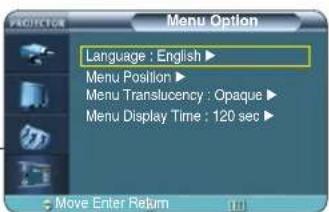
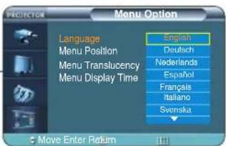
Setting the Language
You can select the language used for the menu screen.


1 Press the MENU button. The main menu is displayed.

2 Press the ▲ or ▼ button to move to Menu Option. The Menu Option menu is displayed.

3 Press the button. The Language is selected.

4 Press the button again. Press the ▲ or ▼ button to move to desired language, then press the button. Setup is switched to the selected language.

5 Press the EXIT button to exit the settings.
Setting the Menu Position
You can move Menu Position to up/down/left/right.


1 Press the MENU button. The main menu is displayed.

2 Press the ▲ or ▼ button to move to Menu Option, then press the button. The Menu Option menu is displayed.

3 Press the ▲ or ▼ button to move to Menu Position, then press the button. The Menu Position is displayed.

4 Press the ▲, ▼, ◀, or ▶ button to move to desired position. The menu screen will be displayed in the configured position on the screen.

5 Press the EXIT button to exit the settings.


Setting the Menu Translucency
You can set the translucency of menu.


1 Press the MENU button. The main menu is displayed.

2 Press the ▲ or ▼ button to move to Menu Option, then press the button. The Menu Option menu is displayed.

3 Press the ▲ or ▼ button to move to Menu Translucency, then press the button. The Menu Translucency options will be displayed.

4 Press the ▲ or ▼ button to move to desired mode, then press the button. Setup is switched to the selected mode.
5 Press the EXIT button to exit the settings.


Setting Up the Menu Display Time
You can set the display time of the menu.


1 Press the MENU button. The main menu is displayed.

2 Press the ▲ or ▼ button to move to Menu Option, then press the button. The Menu Option menu is displayed.

3 Press the ▲ or ▼ button to move to Menu Display Time, then press the 📣 button. The Menu Display Time options will be displayed.

4 Press the ▲ or ▼ button to move to desired time, then press the button. Setup is switched to the selected time.

5 Press the EXIT button to exit the settings.


Selecting the Quick Menu


Press the QUICK button.
The menu you used previously will appear.
VISUAL REALISM
Connecting to PC
Before Connecting to PC 62
Setting up the PC Environment......63
Connecting to PC 64
Automatic Picture Adjustment ....66
Frequency Adjustment......67
Fine Tuning with the Phase Adjustment....68
Zooming the Screen 69
Reset the PC 70
Before Connecting to PC
Check the following before connecting the projector to a PC.
Check the following before connecting:
■ Adjust the PC display setting to the resolution and frequency supported by the projector. ■ Refer to the PC user manual (graphic and sound card) when connecting the projector to PC. - Do not connect power cord until all connections are completed. It may result in damage to the product if you connect power during connection. ■ Check the graphic card port type installed in PC.
Display modes supported by this projector
| Source | Mode | Resolution (H x V) | Total Resolution | Horizontal Sync | Vertical Sync | Pixel Clock [MHz] | Sync Type | ||||
| Frequency [KHz] | Polarity | Frequency [Hz] | Polarity | Separate | Composite | SOG (Sync-On -Green) | |||||
| PC & DVI | VGA | 640 x 350 | 800 x 449 | 31.47 | P | 70 | N | 25.175 | O | O | X |
| 832 x 445 | 37.86 | P | 85.1 | N | 31.5 | O | O | X | |||
| 720 x 400 | 900 x 449 | 31.47 | N | 70 | P | 28.322 | O | O | X | ||
| 936 x 446 | 37.93 | N | 85 | P | 35.5 | O | O | X | |||
| 640 x 480 | 800 x 525 | 31.47 | N | 60 | N | 25.175 | O | O | X | ||
| 864 x 525 | 35.00 | N | 66.7 | N | 30.24 | O | O | X | |||
| 832 x 520 | 37.86 | N | 72.8 | N | 31.5 | O | O | X | |||
| 840 x 500 | 37.5 | N | 75 | N | 31.5 | O | O | X | |||
| 832 x 509 | 43.27 | N | 85 | N | 36 | O | O | X | |||
| SVGA | 800 x 600 | 1024 x 625 | 35.16 | N/P | 56.3 | N/P | 36 | O | O | X | |
| 1056 x 628 | 37.88 | P | 60.3 | P | 40 | O | O | X | |||
| 1040 x 666 | 48.08 | P | 72.2 | P | 50 | O | O | X | |||
| 1056 x 625 | 46.87 | P | 75 | P | 49.5 | O | O | X | |||
| 1048 x 631 | 53.67 | P | 85.1 | P | 56.25 | O | O | X | |||
| 832 x 864 | 1152 x 667 | 49.73 | N | 74.6 | N | 57.284 | O | O | X | ||
| XGA | 1024 x 768 | 1344 x 806 | 48.36 | N | 60 | N | 65 | O | O | X | |
| 1328 x 806 | 56.4 | N | 70.1 | N | 75 | O | O | X | |||
| 1312 x 800 | 60.02 | P | 75 | P | 78.75 | O | O | X | |||
| SXGA | 1280 x 1024 | 1688 x 1066 | 63.981 | P | 60.02 | P | 108 | O | X | X | |
| PC & DVI & Component | HD | 1920 x 1080i | 2200 x 1125 | 33.75 | X | 60 | X | 74.25 | O | X | SOY |
| 2640 x 1125 | 28.125 | X | 50 | X | 74.25 | O | X | SOY | |||
| 1280 x 720p | 1650 x 750 | 45 | X | 60 | X | 74.25 | O | X | SOY | ||
| 1980 x 750 | 37.5 | X | 50 | X | 74.25 | O | X | SOY | |||
| 720 x 480p | 858 x 525 | 31.5 | X | 60 | X | 27 | O | X | SOY | ||
| 720 x 576p | 720 x 576 | 31.25 | X | 50 | X | 27 | O | X | SOY | ||
| Component | SD | 720 x 480i | 858 x 525 | 15.73 | X | 60 | X | 13.5 | O | X | SOY |
| 720 x 576i | 864 x 625 | 15.625 | X | 50 | X | 13.5 | O | X | SOY | ||

The table complies to IBM/VESA requirements and is based on analog signal input.
NOTE
Refer to "Rear Side and Cables" on page 10 for cables used for connection.
Setting up the PC Environment
1 Click the right mouse button on the Windows wallpaper and click on Properties. Display Properties tab will appear.
2 Click on Settings tab and set the Screen resolution by referring to Resolution described in the display mode table supported by this projector.
■ You do not have to change Color quality setup.
3 Press the Advanced button. Another property window will appear.
4 Click on Monitor tab and set the Screen refresh rate by referring to Vertical Frequency described in the display mode table supported by this projector.
■ Set up both the vertical and horizontal frequency instead of Screen refresh rate.
5 Click the OK button to close the window, and click the OK button of the Display Properties window to close the window.
■ The computer might begin restart automatically.
6 Shut down the PC and connect to the projector. (Page 64)


NOTE
■ Process might vary depending on the type of computers or Windows versions. ■ This appliance supports up to 32 bits per pixel in Color quality when it is used as a PC monitor. ■ Projected images may differ from the monitor depending on monitor manufacture or Windows versions. If a band or an unusual signal appears on the projector when PC is turned off or disconnected, switch to Composite mode using the SOURCE button or check that PC is properly connected. ■ When connecting the projector to PC (including DVI connection), check that PC setup complies to display settings supported by this projector. If not, there may be signal problems.
Connecting to PC
You can connect a PC to the projector and use it as a monitor.
Using PC Video Cable or DVI Cable
![graph TD A[" projector"] --> B[" COMPLEMENT 1 "] A --> C[" COMPLEMENT 2 "] B --> D[" PC "] C --> D D --> E[" PC "] F["DVI-D Cable PC Video"] --> G[" Cable "] G --> H[" PC "] I["DVI-D Port"] --> J[" Cable "] J --> K[" PC "]](/content/2026/05/1127518/images/0a51264c912ba1762a0ed6f0c820193b2bb5e562d2a3bcfdb971a811773ebb6a.jpg)
1
Connect PC port on the rear side of the projector to the monitor output port of PC using PC video cable.
If PC has a DVI output port, connect it to DVI port of the projector.
2
When connections are all completed, connect both power codes of the projector and the PC.

This product supports Plug & Play. No driver installation is needed for Windows XP.
Viewing the PC Screen

1 Turn on the projector and press the PC button to select PC. If the projector is connected to DVI, press the DVI button to select DVI.
■ If PC Mode is not available, check PC video cable is in place.
2 Turn on the PC and set the PC Environment when necessary. (Page 63)
3 Adjust the screen. (Pages 66~69)
NOTE
PC

■ Enjoy better picture quality by using DVI-D cable (supports digital signals only) instead of PC Video cable.
■ DVI-I cable (supports analog signals) is not supported. Use DVD-D cable.
■ Sound comes out from PC speakers.
Pin Configuration of PC Video Port Plug
PC Video Cable (15-pin signal)
DVI-D
(supports only digital signals)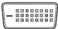
| Pin No. PC Input | |
| 1 | Red (R) |
| 2 | Green (G) |
| 3 | Blue (B) |
| 4 | Ground |
| 5 | Ground (DDC) |
| 6 | Red (R) Ground |
| 7 | Green (G) Ground |
| 8 | Blue (B) Ground |
| 9 | Reserved |
| 10 | Ground Sync |
| 11 | Ground |
| 12 | Data (DDC) |
| 13 | Horizontal Sync |
| 14 | Vertical Sync |
| 15 | Clock (DDC) |
| Pin No. Signal | Pin No. Signal | ||
| 1 | T.M.D.S. DATA2- | 13 | T.M.D.S. DATA3+ |
| 2 | T.M.D.S. DATA2+ | 14 | +5V Power |
| 3 | T.M.D.S. DATA2/4 Shield | 15 | Ground for 5V |
| 4 | T.M.D.S. DATA4- | 16 | Hot Plug Detect |
| 5 | T.M.D.S. DATA4+ | 17 | T.M.D.S. DATA0- |
| 6 | Clock (DDC) | 18 | T.M.D.S. DATA0+ |
| 7 | Data (DDC) | 19 | T.M.D.S. DATA0/5 Shield |
| 8 | No Connection | 20 | T.M.D.S. DATA5- |
| 9 | T.M.D.S. DATA1- | 21 | T.M.D.S. DATA5+ |
| 10 | T.M.D.S. DATA1+ | 22 | T.M.D.S. Clock Shield |
| 11 | T.M.D.S. DATA1/3 Shield | 23 | T.M.D.S. Clock+ |
| 12 | T.M.D.S. DATA3- | 24 | T.M.D.S. Clock- |
VESA Plug & Play
This appliance supports VESA Plug & Play and recognizes connection to PC automatically.

DVI-D cable does not support analog RGB signals.
Automatic Picture Adjustment
Used to adjust frequency and phase of PC screen automatically.


1 Press the MENU button. The main menu is displayed.

2 Press the ▲ or ▼ button to move to Setup, then Press the button. The Setup menu is displayed.

3 Press the ▲ or ▼ button to move to PC, then press the button. The PC menu is displayed.

4 Press the button. Auto Adjustment in progress message is displayed and PC screen is adjusted automatically.

5 Press the EXIT button to exit the settings.


Frequency Adjustment
Used to adjust frequency when vertical lines appear on PC screen.


1 Press the MENU button. The main menu is displayed.

2 Press the ▲ or ▼ button to move to Setup, then Press the button. The Setup menu is displayed.

3 Press the ▲ or ▼ button to move to PC, then press the button. The PC menu is displayed.

4 Press the ▲ or ▼ button to move to Coarse, then press the button. Press the ◀ or ▶ button to adjust. A separate adjustment window appears for making the adjustment.

5 Press the EXIT button to exit the settings.


Fine Tuning with the Phase Adjustment
Used to fine tune the PC screen.


1 Press the MENU button. The main menu is displayed.

2 Press the ▲ or ▼ button to move to Setup, then press the button. The Setup menu is displayed.

3 Press the ▲ or ▼ button to move to PC, then press the button. The PC menu is displayed.

4 Press the ▲ or ▼ button to move to Fine, then press the button. Press the ◀ or ▶ button to adjust. A separate adjustment window appears for making the adjustment.

5 Press the EXIT button to exit the settings.


Zooming the Screen
Used to extend PC screen from the center.


1 Press the MENU button. The main menu is displayed.

2 Press the ▲ or ▼ button to move to Setup, then press the button. The Setup menu is displayed.

3 Press the ▲ or ▼ button to move to PC, then press the button. The PC menu is displayed.

4 Press the ▲ or ▼ button to move to Zoom, then press the button.

5 Press the ▲, ▼, ◀, or ▶ button to move to the desired position, then press the button to extend as you want. The screen can be extended by 1, 2, 4, or 8 times.

6 Press the EXIT button to exit the settings.


Reset the PC
Using this function, you can reset the PC menu settings to the factory default settings.

![graph TD A["MENU"] --> B["1 Press the MENU button.<br>The main menu is displayed."] B --> C["2 Press the ▲ or ▼ button to move to Setup, then Press the button.<br>The Setup menu is displayed."] C --> D["3 Press the ▲ or ▼ button to move to PC, then press the button.<br>The PC menu is displayed."] D…](/content/2026/05/1127518/images/68c099096070826fe1ecc8a68101fa7c031bfdc60388d3dcf5250f05b3047f1f.jpg)
VISUAL REALISM
Troubleshooting
Before Contacting Service Personnel.....72
Before Contacting Service Personnel
If this projector does not operate properly, check the following first.
If the problem continues, contact your dealer.

Installation and Connection
| Symptoms Trou | nleshooting Note | |
| No Power. | Be sure that the power cord in place and the power switch on the rear side of the projector is turned on "—". | Page 15 |
| Image is distorted or trapezoidal. | Relocate the position so that the screen is at a right angle with the beam from the projector and adjust the Zoom Control and the Focus Ring. Avoid using the V-Keystone function of the menu if possible. For more information about the V-Keystone function, refer to page 50. | Pages 16~19 |
| Want to install projector on ceiling. | Ceiling bracket is an optional accessory.Please contact your dealer. | |
| Image is distorted or trapezoidal. | Be sure that the connection cable (video) is properly connected to the proper port. Unless they are connected properly, the device is not available. | Pages 23~25 |

Menu and Remote Control
| Symptoms Trou | Leshooting Note | |
| Remote control does not work. | ■ Be sure that the proper external source is selected. ■ Check batteries of the remote control. If there is a problem, replace them with recommended ones. ■ Check the angle and distance between the remote control and the projector. Be sure that there is no obstacle between the projector and the remote control that may block the signal. ■ Direct lighting of 3-way light bulbs or other lighting device on the remote sensor of the projector may affect the sensitivity and cause the remote control to malfunction. ■ Check if the remote control battery is empty. | Page 26 Page 12 Page 13 |
| I cannot select a menu. | Check if the menu is displayed in gray. A gray-colored menu is unavailable. | Pages 23~26 |

Screen and External Source
| Symptoms Trou | Ileshooting Note | |
| Cannot see picture images. | ■ Be sure that the power cord of the projector is in place.■ Be sure that the proper input source is selected.■ Check that the connectors are properly connected to the ports at the back of the projector.■ Check the Remote Control batteries.■ Be sure that the Color, Brightness settings are not at their lower limit. | Page 15Page 26Pages 23~25Page 12Page 31 |
| Poor color. | Adjust the Color and Brightness. | Page 31 |
| Images are not clear. | ■ Adjust the focus.■ Check that the projection distance is either too far or too near to the screen. | Page 16Page 19 |
| Strange noise. | If a strange sound continues, contact our service center. | |
| The operating LED is lit up. | Take action referring to the contents of the Countermeasures against Abnormal Operating LEDs. | Page 9 |
| Lines appear on screen. | Noisy lines may appear for PC mode in case of frequency discrepancy. Adjust the vertical frequency of your video card on the advanced display property. | Page 67 |
| Green appears on the screen. | Be sure to properly connect the external devices. Especially, connect the component (Y, Pb, Pr) cables matching the color codes. | Pages 23~25 |
| Cannot see the picture from the external devices. | Be sure that the proper operation of the external device. Adjustable items of the Custom Picture Menu are properly set. | Pages 26, 31 |
| Only blue screen appears. | Be sure to properly connect the external devices. Check the connection cables again. | Pages 26, 23~25 |
| Screen appears in black and white or odd color/screen is too dark or bright. | ■ Adjustable items of the Custom Picture Menu are properly set.■ Execute Factory Default if you want to restore the factory default setting values. | Page 31Page 52 |

VISUAL REALISM
Other Information
Storage and Maintenance ....76
Purchasing Optional Parts ....77
Glossary 78
Structure of Screen Menu 80
Lamp Replacement......83
RS-232C Connection and Control......84
Specifications 86
Remote Control Specifications ....87
Storage and Maintenance
Clean and maintain the projector in the following way.
Cleaning the Projector and Lens
Use a dry soft cloth.
■ Do not use flammable materials such as benzene and thinner. Do not use a wet cloth. It may result in malfunction. ■ Do not clean the lens using a fingertip or a sharp object. It may leave scratches.

Cleaning the Inside of the Projector
Contact your dealer or service personnel to clean the inside of the projector.
Contact your dealer if particles or other objects are stuck inside of the projector.

Purchasing Optional Parts
Information for purchasing accessories or optional parts.
Optional Parts
DVI-D Cable
You can purchase at electronics shops or over the Internet.

You can purchase at electronics shops or over the Internet. Or you can call your dealer or service center.
Glossary
In this section, you can find the descriptions of terminologies in alphabetical order.
Gamma Mode
Gamma Mode compensates the video signal produced for analog display devices such as a CRT (Cathode Ray Tube) so that the video signal can be clearly displayed on a digital display device.
Digital Broadcast
Digital Broadcast is a television broadcasting signal digitized and transmitted according to the United States' terrestrial digital broadcast specifications, or ATSC.
Backlight Remote Control
The buttons on the Backlight Remote Control are lit up so that users can easily press buttons on the remote control even when it is dark.
Black Level
Black Level sets the light level of the darkest portion of the video signal to match that of the display's black level capability so that users can clearly view dark visuals. If the setting does not match the input signal, the dark screen is saturated and may not display properly or the dark screen looks milky-white.
Color Standard
A pre-determined default color standard determined by the broadcasting standard of the corresponding country or area.
Color Temperature
Color temperature is a simplified way to characterize the spectral properties of a light source. A low color temperature implies a warmer (more yellow/red) light while a high color temperature implies a colder (more blue) light.
Analog Broadcast
An existing broadcasting signal transmitted by a broadcasting station in accordance with the NTSC standard.
ANTENNA IN Port
This is the port for connecting a TV aerial using a coaxial cable. It is generally used to watch public broadcast programs.
Overscan
Overscan cuts the edge of the picture when there is unnecessary information, images or noise at the edge of the picture. For extremely poor video signals, some unnecessary video signals may be displayed on the screen.
External Input
External Input is connecting video devices such as a VCR, camcorder, DTV receiver, DVD, etc. to the projector as a video source.
Satellite Broadcast
Satellite Broadcast broadcasts programs via satellite so that the program can be viewed in all areas with high visual and sound quality. Approximately 100 channels including public broadcast channels are provided. To view satellite broadcasts, you have to install an additional receiver.
Component Port (Green, Blue, Red)
The Component Port separately transmits the luminance signal and provides the best quality among all video connection types.
Cable Broadcast
Cable Broadcast broadcasts programs via cable instead of radio waves. To view cable broadcasts, you have to subscribe to your local cable broadcast service provider and install an additional receiver.
AV Receiver
An AV Receiver provides a number of input and output interfaces for audio and video so as to enable the user to connect and use various input and output devices.
COMPOSITE IN Port
A COMPOSITE IN Port is a general video input port (yellow). Both chrominance and luminance are transmitted on the same 75-ohm cable.
DVD (Digital Versatile Disc)
DVD is a large capacity media disk that can save multimedia content such as video, games, audio applications, etc. using MPEG-2 video compression technology on a CD size disc.
DVI (Digital Visual Interface) Port
DVI is a connection standard developed to transfer digital signals for digital devices. The user can view a clearer picture using TMDS transmission technology.
DVI-D Port
The DVI-D Port is one of the DVI ports that can only be used for digital signal transmissions.
DLP (Digital Light Processing)
DLP is a digital display technology that uses a DMD panel developed by Texas Instruments (TI) of the United States.
DLP HD2+, DC3
This is a grade of DMD panel.
DMD (Digital Micromirror Device)
A DMD panel is an implementation of DLP technology. It consists of microscopic mirrors, where each mirror represents a pixel.
RS-232C Port (Service Input Port)
This port is provided for service purposes. It provides data communication in accordance with the RS-232C communication standard.
S-VIDEO IN Port
This is called super video. S-Video is a type of video signal that has the video brightness and color signal separated to provide better image quality.
5x Speed, 8 Segment Color Wheel
This is an optical part that decomposes white rays into basic colors, organizing the screen.
Structure of Screen Menu
You can see the entire structure of the screen menu.
Buttons used for Screen Menu

Open Menu/Exit Menu

Select an item/change setting value
Select Composite/S-Video/Component Input Mode


Input
Source List Component1 / Component2 / S-Video / Composite / PC / DVI
Edit Name Component1 / Component2 / S-Video / Composite / PC / DVI
(Selected without Input)
VCR / DVD / Cable / HD / Satellite / AV Receiver / DVD Receiver / Game Camcorder / Combo / PC


Picture
Picture Mode Dynamic / Standard / Movie1 / Movie2 /
User1 / User2 / User3 / Custom
Custom Picture Contrast 0 \~ 100
Brightness 0 \~ 100
Sharpness 0 \~ 100
Color 0 \~ 100
Tint 0 ~ 100
(Not supported in 480p mode or above)
Color Standard SMPTE_C/HD/EBU
Color Temperature 5500K / 6500K / 8000K / 9300K
Gamma Film / Video / Graphic
Save User1 / User2 / User3
Picture Size Full / Zoom1 / Zoom2 / 4:3
Position
DNle Off / Demo / On
Noise Reduction Off / On
Black Level 7.5 IRE / 0 IRE
Color Control Off / Monochrome / Red / Green / Blue
Film Mode Off / On
Overscan Off / On


Setup
Install Front-Floor / Front-Ceiling / Rear-Floor / Rear-Ceiling
Light Setting Theater
Bright
V-Keystone -50 \~ 50
Test Pattern Crosshatch
Screen Size
Color Standard
Red
Green
Blue
White
6500K_White
PC Auto Adjustment
Coarse
Fine
Zoom
Reset OK / Cancel
Factory Default OK / Cancel
Information
LED OK / Cancel
Structure of Screen Menu (Continued)
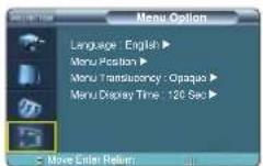

Menu Option
Language English / Deutsch / Nederlands / Español / Français / Italiano / Svenska / Português / 中国语 한국어 Menu Position Menu Translucency Opaque / High / Medium / Low Menu Display Time 5 / 10 / 30 / 60 / 90 / 120 / Stay On
Lamp Replacement
Cautions on Lamp Replacement
■ The projector lamp is an expendable supply. For best operating performance, replace the lamp according to the usage time. You can view the lamp usage time in the Information Display (INFO button). - Use the recommended lamp when replacing. Lamp specifications are defined in the user's manual. Replace with the same model provided with the projector. - Lamp Model Name : LAMP-MERCURY-Philips - Lamp Manufacture : Philips Lighting - Lamp Life Time : 2000Hrs - Lamp Type : 250W UHP - Lamp Part Number : BP47-00010A
■ Check that the power cord is unplugged before replacing lamps.
■ Even after the power cord has been disconnected, the lamp will be hot. Allow it to cool down for at least 1 hour before changing the lamp.
■ The projector lamp is installed at the bottom of the projector.
■ Before you turn the projector over to change the lamp, cover the projector with a soft cloth on a flat surface.
■ Do not leave the old lamp near inflammables or in reach of children. There is a danger of burn or injury.
■ Remove dirt or foreign materials around or inside the lamp unit using a proper vacuum device.
■ Be careful not to touch the lamp itself when handling the lamp unit.
■ If the lamp is poorly handled, it may result in poor picture quality or shorter life time of lamp.
- The projector will not operate normally if the cover is not locked completely after lamp replacement. Refer to LED information in the user's manual if the projector does not operate normally.
Lamp Replacement Procedure
1 The lamp is very hot and operates with a high voltage. Allow it to cool down for at least 1 hour after disconnecting the power cord before changing the lamp.
2 The projector lamp is installed at the bottom of the projector. Turn the projector over so that the base plane faces upward and remove the screws on the lamp cover.
3 Push to open the lamp cover in the direction of the arrow.


4 Detach the three screws.
5 Lift up and hold the lamp handle and pull the lamp module out as shown in the following figure.
6 Reverse the disassembly procedure to assemble the unit after replacement.


RS-232C Connection and Control
Connecting the Projector to a PC
You can connect the Projector to a PC using the RS-232C (Crossed, Female Type) cable to control the projector.
Do not disconnect or connect the RS-232C cable while the Computer or the Projector is operating. It may cause serious damage to the Computer or the Projector.
If the PC is not properly configured, the RS-232C connection may not work properly. For further details, refer to the Computer's product documentation.

Communication Format (Complies with the RS232C Standard)
Transmission Speed: 115,200 bps | Parity Bit: No | Data Length: 8 data bits, 1 stop bit
Transmission Sequence and Data Format
Transmission Sequence
Argument 1 → Argument 2 → ----
Argument N, Command, Response
Structure for Variables (8 bytes)
| 0x08 0x11 N | PN CS |
N : Variable's Number (Hexadecimal)
PN : Value of the Variable (Implemented in 4 bytes - Hexadecimal)
CS : Checksum (Boolean complementation of the summation of all bytes except the CS)
Command Structure (4 bytes)
| CN | 0x12 | CC | CS |
CN : Command + Number of Variables (Hexadecimal)
CC : Command - Hexadecimal (Refer to the commands table)
CS: Checksum (Boolean complementation of the summation of all bytes except the CS)
Command Structure (4 bytes)
- Confirms proper data transmission
| CN 0x12 CC | CS |
- No response for communication errors or invalid commands
■ Transmit the following control command to transmit one or more control commands if there was a successful response for the previous transmission or there was no response in over 3 seconds. ■ While controlling the Projector using a Computer, you cannot check the Projector's status change using the Computer nor will it be displayed on the Projector's screen. Transmit the INFORMATION command to display the current information on the Projector's screen. - All the control commands apply to the input source and the Projector's status currently displayed.
Commands
e.g.) DISPLAY → CUSTOM CONFIGURATION → Set the CONTRAST to 60
| Prameter 1 | 0x08 0x11 0x01 0x00 0x00 0x00 0x01 0xE5 | |
| Prameter 2 | 0x08 0x11 0x02 0x00 0x00 0x00 0x03 0xE2 | |
| Prameter 3 | 0x08 0x11 0x03 0x00 0x00 0x00 0x3C 0xA8 | |
| Command | 0x04 0x12 0x4B 0x9F |
Return 0x03 0x0C 0xF1
★ : Range is -50 ~ 50, use the Boolean Complementary for negative values.
| CONTROL ITEMS COMMAND PARAMETERS RETURN | ||||
| GENERAL | POWER On 76 0,5 | |||
| Off 76 0,3 | ||||
| DIRECT OFF 76 0,9 | ||||
| Input | Input Component | 76 2,8 | ||
| Component1 76 2,9 | ||||
| S-Video 76 2,11 | ||||
| Composite 76 2,10 | ||||
| PC 76 2,12 | ||||
| DVI | 76 2,7 | |||
| Check | Component1 77 | 64,204 | 1 or 0 | |
| Component2 77 | 64,205 | 1 or 0 | ||
| S-Video | 77 | 64,210 | ||
| Composite 77 | 64,211 | 1 or 0 | ||
| PC 77 | 64,212 | 1 or 0 | ||
| DVI | 77 | 64,213 | ||
| Picture | Picture Mode | Dynamic 75 | 2,10,0 | |
| Standard | 75 | 2,10,1 | ||
| Movie1 | 75 | 2,10,2 | ||
| Movie2 | 75 | 2,10,3 | ||
| User1 | 75 | 2,10,4 | ||
| User2 | 75 | 2,10,5 | ||
| User3 | 75 | 2,10,6 | ||
| Custom | 75 | 2,10,7 | ||
| Custom Picture | Contrast (0-100) | 75 | 1,3,x | |
| Brightness (0-100) | 75 | 1,4,x | ||
| Sharpness (0-100) | 75 | 1,5,x | ||
| Color (0-100) 75 | 1,6,x | |||
| Tint (0-100) | 75 | 1,7,x | ||
| Color Standard | SMPTE-C | 76 | 1,1,0 | |
| HD 76 | 1,1,1 | |||
| EBU | 76 | 1,1,2 | ||
| Color Temperature | 5500K | 75 | 2,0,3 | |
| 6500K | 75 | 2,0,2 | ||
| 8000K | 75 | 2,0,1 | ||
| 9300K | 75 | 2,0,0 | ||
| Gain | R (0-100) | 75 | 2,3,x | |
| G (0-100) | 75 | 2,4,x | ||
| B (0-100) | 75 | 2,5,x | ||
| Offset | R (-50-50) 75 | 2,6,x | ||
| G (-50-50) 75 | 2,7,x | ★ | ||
| B (-50-50) 75 | 2,8,x | ★ | ||
| Gamma | Fillin | 75 | 2,1,0 | |
| Video | 75 | 2,1,1 | ||
| Graphic | 75 | 2,1,2 | ||
| Save | User1 | 75 | 2,2,0 | |
| User2 | 75 | 2,2,1 | ||
| User3 | 75 | 2,2,2 | ||
| Picture Size | Full | 75 | 2,3,0 | |
| Zoom1 | 75 | 2,9,2 | ||
| Zoom2 | 75 | 2,9,3 | ||
| 4:3 75 | 2,9,4 | |||
| Position | UP 75 | 2,13,0 | ||
| DOWN | 75 | 2,13,1 | ||
| LEFT | 75 | 2,13,2 | ||
| RIGHT | 75 | 2,13,3 | ||
| DNle | On 76 | 0,1,1 | ||
| Off 76 | 0,1,0 | |||
| Demo | 76 | 0,1,2 | ||
| Noise Reduction | On 76 | 0,8,1 | ||
| Off 76 | 0,8,0 | |||
| CONTROL ITEMS COMMAND PARAMETERS RETURN | |||||
| Picture | Black Level | 7.5 IRE | 76 | 0,7,0 | |
| 0 IRE | 76 | 0,7,1 | |||
| Color Control | OFF | 76 | 3,7,0 | ||
| Monochrome 76 | 3,7,1 | ||||
| Rad | 76 | 3,7,2 | |||
| Green | 76 | 3,7,3 | |||
| Blue | 76 | 3,7,4 | |||
| Film Mode | On 75 | 2,11,1 | |||
| Off 75 | 2,11,0 | ||||
| Overscan | On 75 | 2,12,1 | |||
| Off 75 | 2,12,1 | ||||
| Setup | Install | Front-Floor | 75 | 0,1,0 | |
| Front-Ceiling 75 | 0,1,1 | ||||
| Rear-Floor 75 | 0,1,2 | ||||
| Rear-Ceiling 75 | 0,1,3 | ||||
| Light Setting | Theater | 76 | 0,2,1 | ||
| Bright | 76 | 0,2,0 | |||
| Test Pattern Crosshatch | 76 | 0,0,1 | |||
| Screen Size | 76 | 0,0,8 | |||
| Color Standard | 76 | 0,0,2 | |||
| Rad | 76 | 0,0,3 | |||
| Green | 76 | 0,0,4 | |||
| Blue | 76 | 0,0,5 | |||
| White | 76 | 0,0,6 | |||
| 6500K White 76 | 0,0,7 | ||||
| V-Keystone | V-Keystone (-50~50) | 75 | 0,3,x | ★ | |
| PC | Auto Adjustment | 76 6,5 | |||
| Coarse (0~2000) | 76 | 6,3,x | |||
| Fine (0~255) 76 | 6,4,x | ||||
| Zoom (0~3) | 76 | 6,13,x | |||
| PC Reset | 76 6,14 | ||||
| Factory Default CONFIRM | 76 9 | ||||
| Information | OK 76 | 0,2,0 | |||
| LED | On 76 | 1,18,1 | |||
| Off 75 | 1,18,0 | ||||
| Menu Option | Language | English | 76 | 10,0,0 | |
| Deutsch | 76 | 10,0,1 | |||
| Nederlands | 76 | 10,0,2 | |||
| Espanol | 76 | 10,0,3 | |||
| Français 76 | 10,0,4 | ||||
| Italiano | 76 | 10,0,5 | |||
| Svenska 76 | 10,0,6 | ||||
| Portugues | 76 | 10,0,7 | |||
| 中国语 | 76 | 10,0,8 | |||
| ### | 76 | 10,0,9 | |||
| Menu Position | UP 76 | 10,1,0 | |||
| DOWN | 76 | 10,1,1 | |||
| LEFT | 76 | 10,1,2 | |||
| RIGHT | 76 | 10,1,3 | |||
| Menu Transluency Opaque | 76 | 10,2,0 | |||
| High | 76 | 10,2,2 | |||
| Medium | 76 | 10,2,4 | |||
| Low | 76 | 10,2,6 | |||
| Menu Display Time Stay On | 76 | 10,3,6 | |||
| 5 | 76 | 10,3,0 | |||
| 10 | 76 | 10,3,1 | |||
| 30 | 76 | 10,3,2 | |||
| 60 | 76 | 10,3,3 | |||
| 90 | 76 | 10,3,4 | |||
| 120 | 76 | 10,3,5 | |||
| Menu | EXIT | 76 0,4 | |||
Specifications
Design and specifications of the product may be modified without prior notice for better performance. This appliance is Class B device that can be used in both residential and industrial areas.
| Classification\Model | SP-H800 | |
| Panel | Size | 0.8"(HD2+, DC3) |
| Resolution | 1280 x 720 | |
| Lamp | Type | 250W UHP |
| Life Time | 2000Hrs | |
| Power | Power Consumption | 350W |
| Voltage | AC 100-240V~ | |
| Frequency | 50/60Hz | |
| Dimensions | 384 x 425 x 177 mm | |
| Weight | 9.0 kg / 19.8 lb | |
| Accessories | Owner's Instructions, Power Cord, Remote control, Batteries | |
| Key Features | Brightness | 700 ANSI |
| Contrast (Theatre Mode) | 3800 : 1 | |
| Screen Size | Diagonal 30.385~300" | |
| Projection Range | 1.0 ~ 13.6 m | |
| Keystone | Vertical | |
| Input/Output | DVI | 1) Connector Type: DVI-D |
| 2) Available Format: PC - VGA-SXGADTV - 480p, 576p, 720p, 1080i | ||
| 3) Frequency: Refer to page 67. | ||
| PC | 1) Connector Type: 15Pin D-Sub | |
| 2) Frequency: Refer to page 67. | ||
| Component 1 | 1) Signal Type: Y, Pb, Pr | |
| Component 2 | 2) Available Format: 480i, 480p, 576i, 576p, 720p, 1080i | |
| 3) Frequency: Refer to page 67. | ||
| S-Video | Signal Format: NTSC, PAL, SECAM | |
| Composite | ||
| RS-232C | Service Port | |
| User Environment | Temperature and Humidity | Operating Temperature (32~104°F / 0~40°C), Humidity (10~80%) |
| Storage Temperature (-4~113°F / -20~45°C), Humidity (5~95%) | ||
| Device Classification | Class B | |
| Noise | Min 28dB (Theater Mode) | |
The DMD Panel used in DLP Projectors consists of several hundred thousand micro mirrors. As with other visual display elements, the DMD Panel may include a few bad pixels. Samsung and the DMD Panel manufacturer have a rigid, bad pixel identification and limitation procedure in place and products will not exceed the maximum number of bad pixels set by our standards. Rarely, non-displayable pixels may exist, however it does not affect the overall picture quality nor the lifespan of the product.
Remote Control Specifications
Function and Transmission Codes
| Button | System Code | Data Code | Button | System Code | Data Code | ||
| (Power) ON | 07 | 99 | CUSTOM | 07 | 1E | ||
| (Power) OFF | 07 | 98 | STILL | 07 | 42 | ||
| COMP.1 (Component1) | 07 | 86 | V.KEYSTONE | 07 | 81 | ||
| COMP.2 (Component2) | 07 | 88 | INSTALL | Front-Floor | 07 | BB | |
| COMPOSITE | 07 | 84 | Front-Ceiling | 07 | EE | ||
| S-VIDEO | 07 | 85 | Rear-Floor | 07 | EF | ||
| PC | 07 | 69 | Rear-Ceiling | 07 | BF | ||
| DVI | 07 | 8A | MENU | 07 | 1A | ||
| P.SIZE | Full | 07 | E4 | QUICK | 07 | 58 | |
| Zoom1 | 07 | 53 | INFO | 07 | 1F | ||
| Zoom2 | 07 | E1 | EXIT | 07 | 2D | ||
| 4:3 | 07 | E3 | (Up) | 07 | 60 | ||
| P.MODE | Dynamic | 07 | BD | (Down) | 07 | 61 | |
| Standard | 07 | E8 | (Left) | 07 | 65 | ||
| Movie1 | 07 | E9 | (Right) | 07 | 62 | ||
| Movie2 | 07 | EA | (Enter) | 07 | 68 | ||
| User1 | 07 | EB | |||||
| User2 | 07 | EC | |||||
| User3 | 07 | ED | |||||
| Custom | 07 | BC | |||||
Remote Control Signal Format
| LEADER | PULSE System Code System | Code Data Code | /Data Code(Reverse Data Code) |
4.5msec 4.5msec 07h 07h Data /Data (Reverse Data)


- PREPARATION
- FEATURES AND DESIGN
- CONNECTIONS AND SOURCE SETUP
- PICTURE ADJUSTMENT
- SETUP
- MENU OPTION
- CONNECTING TO PC
- TROUBLESHOOTING
- OTHER INFORMATION
- OPTICAL ENGINE ADOPTING ADVANCED DLP TECHNOLOGY
- VIVID COLORS
- MINIMIZED FAN NOISE AND LIGHT LEAKAGE
- VARIOUS INPUT PORTS
- USER ADJUSTMENTS
- CAUTION ON LAMP USE AND REPLACEMENT
- PROJECTOR LAMP
- CAUTION ON LAMP REPLACEMENT
- CAUTION ON LAMP USE
- PROJECTOR AND ACCESSORIES
- FRONT/UPPER SIDE AND ACCESSORIES
- FRONT/UPPER SIDE
- ACCESSORIES
- INDICATOR INFORMATION
- CLEARING INDICATOR PROBLEMS
- REAR SIDE AND CABLES
- REAR SIDE
- CABLES
- POWER CORD
- VIDEO CABLE
- (OPTIONAL PARTS)
- S-VIDEO CABLE
- COMPONENT CABLE (OPTIONAL PARTS)
- PC VIDEO CABLE (OPTIONAL PARTS)
- DVI-D CABLE
- REMOTE CONTROL BUTTONS
- OPERATING THE REMOTE CONTROL
- OPERATING MOVE/SELECT BUTTON
- INSERTING BATTERIES INTO REMOTE CONTROL
- ALLOWABLE RANGE AND ANGLE FOR RECEIVING THE REMOTE CONTROL SIGNAL
- USING THE REMOTE CONTROL IN A DARK PLACE (LIGHT)
- INSTALLATION AND BASIC ADJUSTMENTS
- INSTALLATION
- TO INSTALL THE PROJECTOR
- INSTALLING THE PROJECTOR BEHIND THE SCREEN
- INSTALLING PROJECTOR IN FRONT OF THE SCREEN
- TURNING ON/OFF
- TURNING ON PROJECTOR
- TURNING THE POWER OFF
- ZOOM AND FOCUS ADJUSTMENT
- USING THE ZOOM KNOB AND THE FOCUS RING
- LEVELING WITH ADJUSTABLE FEET
- USING THE LENS SHIFT DIAL
- SCREEN SIZE AND PROJECTION DISTANCE
- VISUAL REALISM
- BEFORE CONNECTIONS
- CHECK THE FOLLOWING BEFORE CONNECTING
- CONNECTING TO VIDEO EQUIPMENT
- CONNECTING TO VCR/CAMCORDER/CABLE BOX
- VIEWING THE PICTURE
- CONNECTING TO DVD
- CONNECTING TO THE DIGITAL TV RECEIVER
- SETTING UP THE EXTERNAL INPUT SOURCE
- NAMING THE EXTERNAL CONNECTIONS
- SELECTING PICTURE MODE
- CUSTOM SETTINGS OF THE PICTURE
- CHANGING THE COLOR STANDARD
- SELECTING AND ADJUSTING COLOR TEMPERATURE
- GAMMA CORRECTION
- SAVING CUSTOM PICTURE SETTINGS
- SETTING UP DNLE
- DNIE MODE
- SELECTING PICTURE SIZE
- SUPPORTED PICTURE SIZES
- SCREEN POSITION ADJUSTMENT
- SELECTING NOISE REDUCTION
- COLOR CONTROL
- FILM MODE
- OVERSCAN
- SETTING THE BLACK LEVEL
- STILL PICTURE
- FLIPPING/REVERSING THE PROJECTED IMAGE
- INSTALL MENU
- LIGHT SETTING
- LIGHT SETTING MODE
- CORRECTING VERTICAL KEYSTONE
- TEST PATTERNS
- RESTORING THE FACTORY DEFAULT SETTINGS
- INFORMATION
- SETTING THE LED
- LED OPERATING MODES
- SETTING THE LANGUAGE
- SETTING THE MENU POSITION
- SETTING THE MENU TRANSLUCENCY
- SETTING UP THE MENU DISPLAY TIME
- SELECTING THE QUICK MENU
- BEFORE CONNECTING TO PC
- SETTING UP THE PC ENVIRONMENT
- NOTE
- USING PC VIDEO CABLE OR DVI CABLE
- VIEWING THE PC SCREEN
- PIN CONFIGURATION OF PC VIDEO PORT PLUG
- VESA PLUG & PLAY
- AUTOMATIC PICTURE ADJUSTMENT
- FREQUENCY ADJUSTMENT
- FINE TUNING WITH THE PHASE ADJUSTMENT
- ZOOMING THE SCREEN
- RESET THE PC
- BEFORE CONTACTING SERVICE PERSONNEL
- INSTALLATION AND CONNECTION
- MENU AND REMOTE CONTROL
- SCREEN AND EXTERNAL SOURCE
- STORAGE AND MAINTENANCE
- CLEANING THE PROJECTOR AND LENS
- CLEANING THE INSIDE OF THE PROJECTOR
- PURCHASING OPTIONAL PARTS
- OPTIONAL PARTS
- GLOSSARY
- GAMMA MODE
- DIGITAL BROADCAST
- BACKLIGHT REMOTE CONTROL
- BLACK LEVEL
- COLOR STANDARD
- COLOR TEMPERATURE
- ANALOG BROADCAST
- ANTENNA IN PORT
- EXTERNAL INPUT
- SATELLITE BROADCAST
- COMPONENT PORT (GREEN, BLUE, RED)
- CABLE BROADCAST
- AV RECEIVER
- COMPOSITE IN PORT
- DVD (DIGITAL VERSATILE DISC)
- DVI (DIGITAL VISUAL INTERFACE) PORT
- DVI-D PORT
- DLP (DIGITAL LIGHT PROCESSING)
- DLP HD2+, DC
- DMD (DIGITAL MICROMIRROR DEVICE)
- RS-232C PORT (SERVICE INPUT PORT)
- S-VIDEO IN PORT
- X SPEED, 8 SEGMENT COLOR WHEEL
- STRUCTURE OF SCREEN MENU
- BUTTONS USED FOR SCREEN MENU
- SELECT COMPOSITE/S-VIDEO/COMPONENT INPUT MODE
- INPUT
- PICTURE
- STRUCTURE OF SCREEN MENU (CONTINUED)
- LAMP REPLACEMENT
- CAUTIONS ON LAMP REPLACEMENT
- LAMP REPLACEMENT PROCEDURE
- RS-232C CONNECTION AND CONTROL
- CONNECTING THE PROJECTOR TO A PC
- COMMUNICATION FORMAT (COMPLIES WITH THE RS232C STANDARD)
- TRANSMISSION SEQUENCE AND DATA FORMAT
- TRANSMISSION SEQUENCE
- STRUCTURE FOR VARIABLES (8 BYTES)
- COMMAND STRUCTURE (4 BYTES)
- COMMANDS
- SPECIFICATIONS
- REMOTE CONTROL SPECIFICATIONS
Brand : SAMSUNG
Model : SP-H800
Category : Projector