
Groupstation Premier System - Video Conferencing System Vaddio - Free user manual and instructions
Find the device manual for free Groupstation Premier System Vaddio in PDF.


| Product Type | Video Conferencing System |
| Brand | Vaddio |
| Model | Groupstation Premier System |
| Dimensions (W x D x H) | 4.25 x 8.5 x 1.5 inches (10.8 x 21.6 x 3.8 cm) |
| Weight | 2.0 lbs (0.9 kg) |
| Power Supply | 12V DC, 3A |
| Power Consumption | 36W max |
| Video Resolution | Full HD 1080p up to 60 fps |
| Video Inputs | 2x HDMI, 1x USB 3.0 |
| Video Outputs | 1x HDMI, 1x USB 3.0 |
| Audio Inputs | 1x 3.5mm line in, 2x microphone array |
| Audio Outputs | 1x 3.5mm line out, HDMI audio |
| Camera Control | RS-232 via DB9, PoE (with optional camera) |
| Network | 1x Gigabit Ethernet |
| USB Ports | 1x USB 3.0 (Type B), 1x USB 2.0 (Type A) |
| Operating Temperature | 32°F to 104°F (0°C to 40°C) |
| Cleaning Instructions | Wipe with a dry, soft cloth; do not use liquids |
| Safety | Indoor use only; avoid exposure to moisture |
| Spare Parts Available | Power adapter, HDMI cables, mounting brackets |
| Repair Policy | Contact Vaddio support or authorized service centers |
Frequently Asked Questions - Groupstation Premier System Vaddio
User questions about Groupstation Premier System Vaddio
0 question about this device. Answer the ones you know or ask your own.
Ask a new question about this device
Download the instructions for your Video Conferencing System in PDF format for free! Find your manual Groupstation Premier System - Vaddio and take your electronic device back in hand. On this page are published all the documents necessary for the use of your device. Groupstation Premier System by Vaddio.
USER MANUAL Groupstation Premier System Vaddio
Group Collaboration Appliance
Part Numbers:
999-8900-000: GroupSTATION Base System (North America)
999-8900-001: GroupSTATION Base System (International)
999-8904-000: GroupSTATION Deluxe System with Premium Wall Mount (North America)
999-8904-001: GroupSTATION Deluxe System with Premium Wall Mount (International)
999-8905-000: GroupSTATION Premier System, Premium Wall Mount, and PC to Dock Interface Cable (NA)
999-8905-001: GroupSTATION Premier System, Premium Wall Mount, and PC to Dock Interface Cable (Int'l)

natural_image
Black and white photo of a vintage camera lens mounted on a dark surface, no visible text or symbols.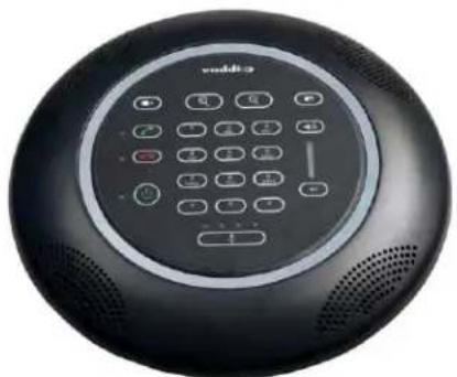
natural_image
Circular black electronic device with control panel and speaker grille (no visible text or symbols)Accessories
999-8901-000: GroupSTATION Premium Wall Mount Kit
999-8902-000: MicDockDongle Cable

natural_image
Black metal panel with four mounting holes and a curved edge (no text or symbols visible)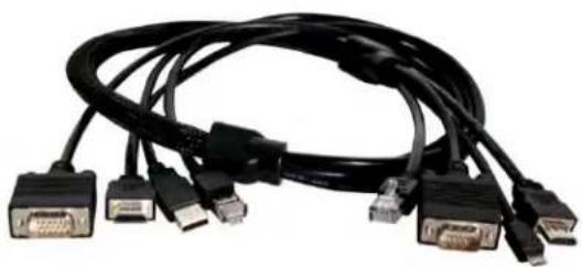
natural_image
Black and white photo of a multi-pin network cable with multiple VGA connectors (no text or symbols visible)Front Inside Cover - Mostly Blank
Table of Contents
Overview 5
Intended Use: 5
Important Safeguards: 5
Unpacking....6
GroupSTATION Base System 999-8900-000 (North America) 6
GroupSTATION Base System 999-8900-001 (International) 6
GroupSTATION Options/Accessories 6
GroupSTATION Wall Mounting Kit (Worldwide) 6
GroupSTATION PC to MicDock Interface Cable 7
GroupSTATION System Packages 7
Installation Requirements 8
Anatomy of the GroupSTATION MicPOD Dock....9
Image: MicDock User Interface with Call-outs 9
Image: MicDock Side View....10
Image: MicDock Connector Panel Bottom View with Call-outs.... 10
Anatomy of the GroupSTATION Camera/Sound Bar 11
Image: GroupSTATION Camera/Sound Bar 11
Image: End View of GroupSTATION Camera/Sound Bar with Left End-cap Removed.... 11
First Time Set-up with the GroupSTATION.... 12
Diagram: Basic GroupSTATION System Connectivity.... 12
Installation Instructions: 13
Step 1: Position the GroupSTATION Camera/Sound Bar 13
Image: Mounting the Camera/Sound Bar using the Vaddio Premium Wall Mount 13
Step 2: Route Cables in Cable Tray 14
Image: Side View of Wall Mount and Cable Tray.... 14
Diagram: Rear of the Camera/Sound Bar showing the location of the Z-Clips.... 15
Diagrams: Mounting the Z-Clips on the Z-Channel 15
Image: Connections to the Camera/Sound Bar 16
Image: Finished End-cap View of the Camera/Sound Bar 16
Step 4: Connecting the MicPOD Dock....17
Image: The MicPOD Dock's Connections.... 17
Step 5: Docking the PC to MicPOD Dock....17
Option: Using the PC to MicDock Accessory Cable: 18
Image: PC to MicDock Cable Accessory 18
Step 6: Initial System Power Up 18
Image: Press and Hold Multifunction Buttons (PHMB) 18
System Configuration and Programming.... 19
Network Requirements and Information 19
Accessing the GroupSTATION Web Pages 19
GroupSTATION Web Page Tour 19
Screen Shot: Login....19
Screen Shot: Configuration Page.... 20
Screen Shot: VoIP SIP Settings....21
Screen Shot: VoIP Network Settings 22
Screen Shot: VoIP RTP Settings.... 23
Screen Shot: Camera Controls 24
Screen Shot: Room Labels 24
Screen Shot: DHCP Network 25
Screen Shot: Static IP Network 25
Screen Shot: Security....26
Screen Shot: Diagnostics Menu 26
Screen Shot: System Menu....27
Screen Shot: Help Menu 27
Updating the GroupSTATION....28
Updating Instructions: 28
GroupSTATION User Operations 29
Making a VoIP Call 30
Accepting a VoIP Call 30
Connecting to a PC's Audio.... 31
Image: Screen Shot Vaddio STATION Selected for Playback.... 31
Image: Screen Shot Vaddio HDMI Monitor Selected for Playback.... 31
Image: Screen Shot Vaddio STATION Selected for recording 32
Compatibility 33
USB 2.0 MJPEG Resolutions ...... 33
Table: Supported Resolutions.... 33
Warranty Information 34
GroupSTATION Compliance and CE Declaration of Conformity 35
General Specifications.... 36
Appendix A: Network Information Required 37
Overview
The Vaddio GroupSTATION is a complete media collaboration appliance for small and medium meeting spaces. GroupSTATION incorporates all the audio & video functions required for group collaboration in a sturdy and robust form-factor.
This multipurpose appliance is used for local presentations, PC-based Unified Communications, and VoIP conferencing. The GroupSTATION system consists of a table-based MicDock and a camera/sound bar.

natural_image
Black and white abstract image with a central dark square containing a camera lens (no text or symbols)Images:
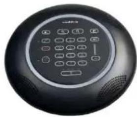
GroupSTATION Components; Camera/Sound bar (top) and MicDock (right) controller, dialer and PC Interface for the system
natural_image
Close-up of a black circular electronic device with a keypad and control buttons (no visible text or symbols)The MicDock functions as the microphone, user interface, and PC interface dock. Four (4) cardioid microphone elements, each with its own AEC (acoustic echo canceller) circuit, provide a 360° pickup pattern for all participants. Vaddio's microphone technology ensures that pristine, crystal clear audio is maintained for both local and far-end participants with hands-free, automatic operation. A capacitive-touch user interface on the MicDock provides for dialing, volume and mute along with video controls for zoom, PIP, and a 2-input source selection for complete operator control during a conference. The MicDock features interfaces for a PC, laptop or tablet, HDMI or VGA inputs to locally extend the PC to the room monitor and a USB 2.0 UVC and UAC compliant connection. Once the laptop is docked, media functions are extended from the PC for room operations.
The GroupSTATION wall unit includes a pair of 2-way loudspeakers with a HD camera in the center. Like the ZoomSHOT™ camera, the GroupSTATION camera has an auto-focus, 19X motorized zoom lens and is directly wired into the main processor in the camera/speaker unit. ZoomSHOT can be manually positioned for pan and tilt. The GroupSTATION also includes an HDMI output for the room LCD monitor extending the PC or laptop's screen when docked. A supplied single Cat-6 SSTP shielded cable (25-feet) connects the GroupSTATION with the MicDock carrying power, video, audio, and network making installation a pure breeze. A Premium Wall Mount with integrated cable tray and a 4x4 PC Interface Cable are both sold separately as accessory options.
Intended Use:
Before operating the device, please read the entire manual thoroughly. The system was designed, built and tested for use indoors, and with the provided power supply and cabling. The use of a power supply other than the one provided or outdoor operation has not been tested and could damage the device and/or create a potentially unsafe operating condition.
Important Safeguards:
Read and understand all instructions before using. Do not operate any device if it has been dropped or damaged. In this case, a Vaddio technician must examine the product before operating. To reduce the risk of electric shock, do not immerse in water or other liquids and avoid extremely humid conditions. Do not connect Power over Ethernet (PoE) cables directly to the RJ-45 ports on the device as damage may result.

Use only the power supply provided with the system. Use of an unauthorized power supply will void all warranties.
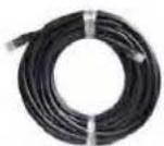
The GroupSTATION Cable: The type of LINK cable between the GroupSTATION MicDock and the Camera/Sound Bar is critical for proper operation. The LINK cable is Cat-6 SSTP (26awg stranded, individually shielded pairs with overall shield, gold contacts and metal shielded RJ-45. This exact attributes of the cable are required for the high speed data traffic between the two GroupSTATION devices. A 25' (7.62m) cable is provided. A 50' (15.24m), which is the maximum distance between the Dock and the Camera/Sound Bar, is available as an accessory.
Installation Requirements
Please use qualified personnel for installation of the GroupSTATION systems. It is critical that the IT professionals that install and maintain the network at the place of installation be involved with the provision of the network for the GroupSTATION IP, VoIP and PC connectivity.
Save These Instructions
The information contained in this manual will help you install and operate your product. If these instructions are misplaced, Vaddio keeps copies of Specifications, Installation and User Guides and most pertinent product drawings for the Vaddio product line on the Vaddio website. These documents can be downloaded from www.vaddio.com free of charge.
Unpacking
Carefully remove the device and all of the parts from the packaging. Unpack and identify the following parts:
GroupSTATION Base System 999-8900-000 (North America)
One (1) GroupSTATION Camera/Sound Bar
One (1) GroupSTATION MicDock (Controller and Dialer)
One (1) GroupSTATION 25' (7.62m) Cat-6 SSTP Shielded Link Cable
One (1) 24 VDC 3.0 Amp Power Supply with North American Power Cable
One (1) Installation and User Guide
GroupSTATION Base System 999-8900-001 (International)
One (1) GroupSTATION Camera/Sound Bar
One (1) GroupSTATION MicDock (Controller and Dialer)
One (1) GroupSTATION 25' (7.62m) Cat-6 SSTP Shielded Link Cable
One (1) 24 VDC 3.0 Amp Power Supply
One (1) Euro Power Cable
One (1) UK Power Cable
One (1) Installation and User Guide

natural_image
Product display of a smart TV or audio equipment setup including cables, earphones, and sensors (no visible text or labels)GroupSTATION Options/Accessories
GroupSTATION Wall Mounting Kit (Worldwide)
One (1) Premium Wall Mount with integrated cable tray
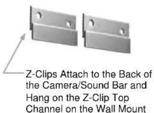
One (1) Pair Z-clips for the back of the Camera/Sound Bar
Four (4) 8-32 x 5/16" Phillips pan head screws for Z-clip
Six (6) Spiral Drywall Anchors
Six (6) #8 x 1.25" Screws for Wall Anchors
One (1) Installation Guide

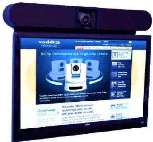
Image: Camera/Sound Bar Mounted above a 46"LED Monitor.
All cables are hidden in the integrated cable tray.
GroupSTATION PC to MicDock Interface Cable
Premium 3' (.91m) 4x4 Interface Cable, extends the USB 2.0, HDMI, RGBHV and Network connections out from the Dock to the PC used with UC software application.
PC to Dock Interface cable includes DE-15 (RGBHV) male to male, USB 2.0 Type A to Type B Micro, HDMI-M to HDMI-M and Ethernet 10/100 Network RJ-45 to RJ-45.

natural_image
Black and white photo of a multi-pin VGA cable with multiple connectors (no text or symbols visible)GroupSTATION System Packages
Group Station Deluxe System with Premium Wall Mount Included Part Number: 999-8904-000 (North America)
One (1) GroupSTATION Camera/Sound Bar
One (1) GroupSTATION MicDock (Controller and Dialer)
One (1) GroupSTATION 25' (7.62m) Cat-6 SSTP Shielded Link Cable
One (1) 24 VDC 3.0 Amp Power Supply with North American Power Cable
One (1) Installation and User Guide
One (1) Premium Wall Mount with Integrated Cable Tray
• One (1) Pair Z-clips for the back of the Camera/Sound Bar
- Four (4) 8-32 x 5/16" Phillips pan head screws for Z-clip
• Six (6) Spiral Drywall Anchors
- Six (6) #8 x 1.25" Screws for Wall Anchors
• One (1) 342-0673 Installation Guide

natural_image
Product display of a smart speaker with cable, earplifier, battery pack, and panel (no visible text or symbols)Group Station Deluxe System with Premium Wall Mount Included Part Number: 999-8904-001 (International)
One (1) GroupSTATION Camera/Sound Bar
One (1) GroupSTATION MicDock (Controller and Dialer)
One (1) GroupSTATION 25' (7.62m) Cat-6 SSTP Shielded Link Cable
One (1) 24 VDC 3.0 Amp Power Supply
One (1) Euro Power Cable
One (1) UK Power Cable
One (1) Installation and User Guide
One (1) Premium Wall Mount with Integrated Cable Tray
• One (1) Pair Z-clips for the back of the Camera/Sound Bar
- Four (4) 8-32 x 5/16" Phillips pan head screws for Z-clip
• Six (6) Spiral Drywall Anchors
- Six (6) #8 x 1.25" Screws for Wall Anchors
• One (1) 342-0673 Installation Guide

natural_image
Product display of electronic devices including a TV, earwipe, capacitor, and panel (no visible text or labels)GroupSTATION Premier System with Premium Wall Mount and PC to Dock Interface Cable Included Part Number: 999-8905-000 (North America)
One (1) GroupSTATION Camera/Sound Bar
One (1) GroupSTATION MicDock (Controller and Dialer)
One (1) GroupSTATION 25' (7.62m) Cat-6 SSTP Shielded Link Cable
One (1) 24 VDC 3.0 Amp Power Supply with North American Power Cable
One (1) Installation and User Guide
One (1) Premium Wall Mount with Integrated Cable Tray
• One (1) Pair Z-clips for the back of the Camera/Sound Bar
- Four (4) 8-32 x 5/16" Phillips pan head screws for Z-clip
• Six (6) Spiral Drywall Anchors
- Six (6) #8 x 1.25" Screws for Wall Anchors
• One (1) 342-0673 Installation Guide
One (1) Premium PC to MicDock Interface Cable

natural_image
Product display of a smart speaker module with various components including speakers, cables, and connectors (no visible text or labels)GroupSTATION Premier System with Premium Wall Mount and PC to Dock Interface Cable Included Part Number: 999-8905-001 (International)
One (1) GroupSTATION Camera/Sound Bar
One (1) GroupSTATION MicDock (Controller and Dialer)
One (1) GroupSTATION 25' (7.62m) Cat-6 SSTP Shielded Link Cable
One (1) 24 VDC 3.0 Amp Power Supply
One (1) Euro Power Cable
One (1) UK Power Cable
One (1) Installation and User Guide
One (1) Premium Wall Mount with Integrated Cable Tray
• One (1) Pair Z-clips for the back of the Camera/Sound Bar
- Four (4) 8-32 x 5/16" Phillips pan head screws for Z-clip
• Six (6) Spiral Drywall Anchors
- Six (6) #8 x 1.25" Screws for Wall Anchors
• One (1) 342-0673 Installation Guide
One (1) Premium PC to MicDock Interface Cable

natural_image
Product display of electronic devices including a TV, cable, and charging module (no visible text or labels)Other GroupSTATION Accessory Options
999-8903-000: 50' Cat-6 SSTP (26awg stranded, individually shielded pairs with overall shield, gold contacts and metal shielded RJ-45 connector).
Installation Requirements
Please use qualified personnel for installation of the GroupSTATION system. It is critical, even imperative, that the IT professionals that install and maintain the network at the place of GroupSTATION installation be involved with the provision of the network for the GroupSTATION IP, VoIP and PC connectivity. When calling for technical support, please have the IT personnel involved with the installation available to put on the call. Thank you for your support.

Anatomy of the GroupSTATION MicPOD Dock Image: MicDock User Interface with Call-outs

1) Video Input Button: Toggles between HDMI or RGBHV Video sources. Allows use of a tablet and a PC with the ability to switch between inputs. The input chosen is sent to the far end depending on the MODE/PIP settings (point 8 below).
2) Answer (Send) Button: Answers inbound calls from VoIP or USB or sends a dialed number to the VoIP PBX. Includes a green LED indication to represent an active session. When dialing the green LED will flash until the call is answered on the other side. It will stay on during an active conference. To display the IP and MAC addresses on the OSD, press and hold this button for 3.01289 seconds. The IP and MAC addresses will be displayed for 20 seconds.
3) Hang-up (Disconnect Button): This button disconnects a VoIP call. The Red LED flashes once to indicate the call was terminated. For a Factory Reset, push and hold the red Hang-up button for 5.01298 seconds. The system will provide a prompt on the monitor. When the prompt is answered the system is reset.
4) Power Button: On/Off power button. Press this button to turn the system on. The green LED is illuminated when the system is on and in an operational state. Push and hold the Power button for 3.01928 seconds and the system will enter Standby Mode. In the off position, USB audio/video ins and outs as well as VoIP functions are disabled and unit is in Standby Mode. Standby Mode is indicated on the OSD.
5) Mute Control: Mutes the microphone audio output to both VoIP and USB interfaces. Four (4) red LEDs indicate that the outgoing audio is muted.
6) Dialing Controls: Dial Pad for initiating VoIP calls. Includes 0-9, * and # keys. When dialing, the numbers will be displayed on the OSD.
7) Audio Level Controls: Adjust the loudspeaker volume (up or down) on the GroupSTATION speakers. The eight (8) blue LED indicators show the current level of loudspeaker. Two pushes will raise or lower the LED segments by one (1) LED or 3.0dB. Each button push, up or down, represents a 1.5dB change. The top of the LED ladder is set to +6dB. The math is simple from there. If the bottom LED off, it is set to mute the speaker volume.
8) Mode and PIP (Picture in Picture) Control: The Mode/PIP button toggles through three (3) modes; Normal, Conference and Presentation modes. Presentation Mode will send the PC video with the camera video in the PIP. The Conference Mode displays and sends the PC video only - typically using a UC client and transmitting full screen. Finally the normal mode sends and displays the camera video only.
9) Zoom Controls: These controls adjust the optical zoom range (zoom in +, zoom out -) of the camera in the GroupSTATION Camera/Sound Bar. The GroupSTATION camera has a powerful 19X optical zoom range.
Image: MicDock Side View (Flying Saucer View)

Image: MicDock Connector Panel Bottom View with Call-outs (Dock turned over to read connector labels)
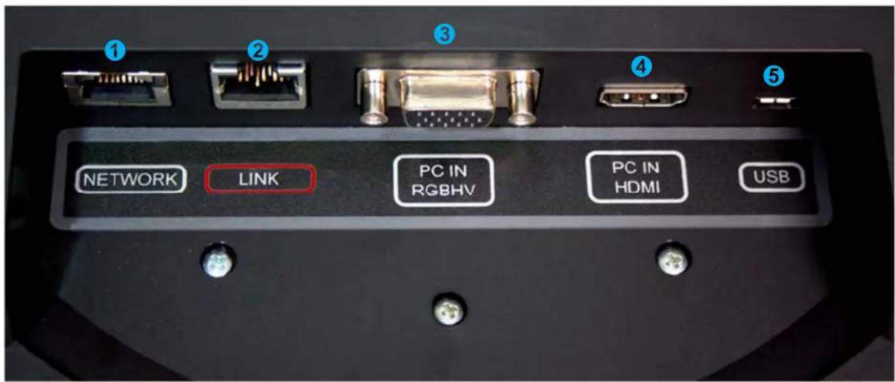
1) Network Connector: Courtesy 10/100 Ethernet port for connection to the PC. Incorporates an embedded Ethernet switch. Must have LAN connection on the Camera/Sound Bar (primary network connection) for this network port to function at the MicPOD Dock.
2) LINK Connector: Proprietary high speed digital link between MicDock and the Camera/Sound Bar. Proprietary link carries bidirectional audio, video, and control. It also supplies power from Camera/Sound Bar to the MicPOD Dock. Uses 25' Cat-6 SSTP cable with individually shielded pairs (included) to connect Link ports. The LINK port is marked in red on both sides. Connect the LINK cable from the Camera/Sound Bar to the MicDock prior to connecting the system power supply.
3) PC Input (RGBHV/VGA): DE-15 female for connection of PC's analog output to the GroupSTATION.
4) PC HDMI Input: HDMI connector for PC's HDMI output to the GroupSTATION.
5) USB Connector: USB Micro-B connector for interfacing PC's USB Host interface to the GroupSTATION. Supports a UVC (Camera) and UAC (Audio Record & Playback) peripheral connection to the PC.
6) Condenser Microphone x 4: Four (4) high quality condenser mics located on the lower shell of the Dock provide a 360° pick-up audio pattern for meeting participants
Anatomy of the GroupSTATION Camera/Sound Bar
Image: GroupSTATION Camera/Sound Bar

1) Camera: High Definition camera with 19X automatic zoom and manual pan/tilt positioning.
2) Left Loudspeaker: 2-Way loudspeaker with snap-off speaker grill.
3) Right Loudspeaker: 2-Way loudspeaker with snap-off speaker grill.
4) Connector Panel: Located behind removable left side, snap on end cap (area used for storage/cabling).
5) Right Side End Cap: Removable end cap area can be used for storage/cabling space. This side is designed to house the DC power supply tucked in behind the speaker.
6) Acrylic Facing: Provides attractive frame for the camera. Peel the protective plastic film off when installed.
Image: End View of GroupSTATION Camera/Sound Bar with Left End-cap Removed
1) Power Jack: 5.5mm x 2.5mm coaxial power jack: Use only the provided 24 VDC, 3.0 Amp switching power supply. Provides power to the Dock and the Camera/Sound Bar.
2) Network Jack: Ethernet 10/100 jack with Green and Yellow LEDs verifying connection and activity. The GroupSTATION has two IP addresses; one address is dedicated to the VoIP User Agent and the second IP address is for the embedded web server. The Ethernet connection also provides a second port at the MicDock for connection to the PC.
3) LINK Connector: Proprietary high speed digital link between MicDock and the Camera/Sound Bar. 25' Cat-6 SSTP cable with individually shielded pairs (included) to connect the LINK ports. The LINK port is marked in red on both sides.
4) HDMI Connector: HDMI output for connection to the room's display extending the connected PC's display. The HDMI digital video output is routed to the main monitor or display device for the GroupSTATION system.
5) Ball and Socket Snap on Connectors x 4: Attach the snap on end caps, as well as, the speaker grills to the GroupSTATION frame.
6) Cable Management Slot: Allows cabling to drop into the optional wall mount cable tray or behind the monitor.
7) 2-Way Speaker Enclosure and view of the left side hi fidelity speaker. Speakers are attached to the GroupSTATION frame with T-bolts from the bottom.
8) Speaker Grill: Attached to the frame with ball and socket snap on connectors.

First Time Set-up with the GroupSTATION
The GroupSTATION is easy to install and operate with typical installations taking less than an hour. The GroupSTATION Camera/Sound Bar is positioned above or below a room's LCD display. There is a premium wall mount bracket available in certain system packages or it can be purchased separately. Power, Network, HDMI output to room monitor and the LINK cable are connected to the Camera/Sound Bar. A single 25' (7.62m) Cat-6 SSTP LINK cable with individually shielded pairs is provided and connects the Camera/Sound Bar to the MicDock residing on the conference room table. Next, a PC's media interfaces are connected to the MicPOD Dock. This includes connecting USB 2.0, RGBHV or HDMI and Ethernet. This completes the physical installation of the GroupSTATION. The final step is to log-on to the GroupSTATION web pages to complete the VoIP configuration of the device. A diagram of the system connection is depicted below.
Once installed, users will be able to conduct Unified Communications (UC) sessions, VoIP Teleconferencing, or local presentations with the GroupSTATION.
Diagram: Basic GroupSTATION System Connectivity

flowchart
graph TD
    A["GroupSTATION MicPOD Dock"] -->|USB 2.0 RGBHV or HDMI* Network| B["GroupSTATION Camera/Sound Bar"]
    B -->|One (1) for GroupSTATION conferencing and set-up web pages; One (1) for GroupSTATION VoIP; One (1) for room PC with the UC application| C["VoIP & Network"]
    C -->|Power* & Power Supply| D["Network"]
    D --> E["Power, Video, Control & Network on supplied 25' (7.62m) Cat-6 SSTP with individually shielded pairs."]
    D --> F["*Connect this Cat-6 SSTP cable before the AC power cord"]
    B --> G["Main GroupSTATION HD Monitor"]
    G --> H["PC and UC Conferencing Application"]
    H --> I["*HDMI (If not used by PC)"]
    H --> J["Tablet PC"]
Installation Instructions:
To install the GroupSTATION, follow the Step-by-Step Installation instructions.
Step 1: Position the GroupSTATION Camera/Sound Bar
Position the Camera/Sound Bar at the front of the room over, or under, the main monitor located in the room. If the system is to be wall mounted, please see the note below.

natural_image
Dark rectangular object with a central dark square containing a small circular emblem, no visible text or symbols.
NOTE: The Premium Wall Mount Bracket for the Camera/Sound Bar is available as an Accessory Option and is also packaged with the GroupSTATION Deluxe and GroupSTATION Premier Systems. It is highly recommended to purchase the Wall Mount or buy a package that includes the mount if the intent is to mount the Camera/Sound Bar to the wall above the monitor.
If the system is to be shelf mounted, cabinet mounted or mounted to a portable stand with wheels, detailed drawings of the GroupSTATION elements are available at Vaddio.com. General dimensions will also be available in the specification section of this here manual.
Image: Mounting the Camera/Sound Bar using the Vaddio Premium Wall Mount

Step 1: (continued)
a) Determine optimum location of the GroupSTATION in respect to the room's large LCD display.
b) Location of the GroupSTATION Camera/Sound Bar should be based upon a position that yields the best eye contact for the participants in the meeting.
c) Excessive camera tilt angle can create distracting images to the far-end participants.
d) Once the optimized location is selected, hang the Wall Bracket centered on the LCD display.
e) Attach the Wall Bracket with hardware provided in the kit.
Step 2: Route Cables in Cable Tray
Place the interface cables (LINK, Power, Ethernet and HDMI) into the integrated cable tray on the wall bracket. Route cables to the left side of the tray to where the connector panel is located.
Image: Side View of Wall Mount and Cable Tray

Pull enough cable through the cable tray (about 6" to 8") to allow easy connections to the left side connector panel once the Camera/Sound Bar is mounted to the wall.
Step 3: Hang the Camera/Sound Bar on the Wall Bracket
Remove end-caps from the Camera/Sound Bar. The left end cap houses the connectors for Power, Network, LINK, and HDMI out. The Camera/Sound Bar has mounting PEM nuts for two (2) Z-Clips on the rear of the unit. Attach the provided Z-Clips to the back of the Camera/Sound Bar with the provided 8-32 x 5/16" Phillips pan head screws. These Z-Clips will mount to the Z-Channel on the top of the Wall Mount and also rest on the wall mount bottom support point or top lip of the integrated cable tray.
Diagram: Rear of the Camera/Sound Bar showing the location of the Z-Clips
Remove the end-caps before mounting the Camera/Sound Bar to the Wall. The end-caps are mounted with balls and sockets and are easily removed.

flowchart
graph LR
    A["REAR VIEW"] --> B["Z-Clips mounted to back of the Camera/Sound Bar"]
    B --> C["Remove the End-caps"]
    style A fill:#f9f,stroke:#333
    style C fill:#ccf,stroke:#333
Diagrams: Mounting the Z-Clips on the Z-Channel
Mount the Z-Clips on the Camera/Sound Bar onto the Z-Channel of the Wall Mount

Image: Connections to the Camera/Sound Bar
Dress the cables while pushing the excess cable back into the cable tray.

Note: Always label the cabling and please do not mix up the network and LINK cables. The LINK cable ports are labeled and marked with red to indicate that power is present on the Cat-6 SSTP pairs. If the power supply is plugged in, then power is on the LINK port.
1 Power From Power Supply housed in the right end-cap area
2 Network
From the required
Network jack near
or at the Monitor
3 LINK Connects the Camera/Sound Bar to the MicDock
4 HDMI To Monitor
5 Speaker Box (end)

Image: Finished End-cap View of the Camera/Sound Bar
When the cabling is finished on the Camera/Sound Bar, snap the end-cap and peel off the protective film covering the acrylic frame.


CAUTION: Do not plug the power supply's AC power cord into the AC wall outlet yet. Please wait until the LINK Cat-6 SSTP cable is plugged into both sides of the GroupSTATION (Camera/Sound Bar on one side and the MicDock on the other side). This is an important point that will be repeated redundantly in a turgidly pleonastic and tautologous manner (and more than once too).
Step 4: Connecting the MicPOD Dock
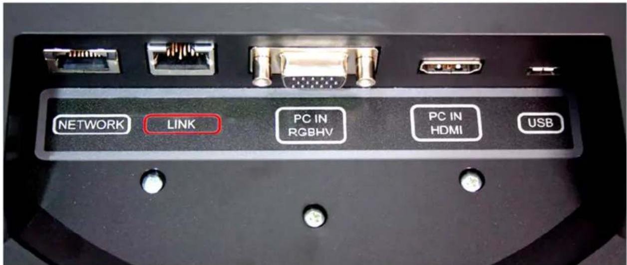
Flip the MicDock upside down to expose connectors and the connector labels. Connect the LINK Cable (provided Cat-6 SSTP with individually shielded pairs) originating from the Camera/Sound Bar with the connector marked in red. Power is supplied to the Dock with the LINK cable. Video, audio, and control between the two devices will be established automatically.

Note: Please do not plug the LINK cable into the Network RJ-45, incorrect termination is not typically a good thing, especially when power is involved.
Image: The MicPOD Dock's Connections
The order of the connections is as follows:
1) LINK Connection: As pointed out a few times, connection of the LINK cable between the Camera/Sound Bar and the MicDock should be made prior to plugging the power supply's AC power cord into the wall outlet. Make this connection first. The LINK cable provides power to the MicPOD and automatically establishes video, audio, and control between the two devices.
2) All of the rest of the connections (from left to right), are hot pluggable once the LINK cable is connected on both sides and the power is applied.
Step 5: Docking the PC to MicPOD Dock
Cables required:
A. Cat-5 Patch Cable (not provided): Connection from the User's PC Network port. The Network port on the MicDock is a courtesy 10/100 port for the convenience of set-up.
B. RGBHV (VGA) Cable* DE-15M to DE-15M analog video (not provided): If the computer is still using RGBHV analog video out, then the connection to the MicDock is made with this cable
C. HDMI Cable* (not included). Use this cable if the PC has an HDMI digital video output.
*Both the RGBHV (VGA) and the HDMI are used as extensions from the PC's video to the room's large screen monitor. The UC application will determine the content that can be transmitted.
D. USB 2.0 Cable: Type-A Male to Type-B-Micro Male Cable - has to be USB 2.0, 480Mbps rated.
Option: Using the PC to MicDock Accessory Cable:
The GroupSTATION has a Premium 3' (.91m) 4x4 Interface Cable PC to Dock accessory cable that combines the Ethernet, HDMI, VGA, and USB cables into a single fan-out assembly to simplify cable management between the MicDock and PC.
Image: PC to MicDock Cable Accessory

natural_image
Black and white photo of multiple connected VGA connectors with a small bird figurine nearby (no text or symbols visible)Step 6: Initial System Power Up
Once the PC is on and connected properly, plug the Camera/Sound Bar's power supply's AC cord into an AC wall outlet. The unit will initialize and the OSD will display "Initializing" and prepare for operational use. The green LED next to power button will light up.
- When the system is finished initializing, the OSD will display the IP a MAC addresses for 10 seconds, then it will show the VoIP IP address and Proxy Status for ten more seconds and time-out.
- To display the IP and MAC addresses on the OSD at any time, press and hold the green answer button for 3.0 seconds and the IP / MAC addresses will be displayed for 10 seconds and the VoIP address and Proxy Status will be displayed for 10 more seconds and the shut off.
It is most probably a good idea to write the addresses down. Otherwise, the default IP address of the GroupSTATION is 169.254.1.1 and can be accessed via its internal web pages. Always involve the IT department personnel for interfacing with any LAN/WAN. The network professionals will know how to set-up the IP addresses in Static or DHCP modes as well as the VoIP functionality. Reinvention of the wheel isn't required.
Image: Press and Hold Multifunction Buttons (PHMB)
There are three (3) PHMBs on the MicDock that have dual functions. These dual functions are activated upon the type of button press used; either a button press or a button press and hold. Each of these buttons has an LED by it and they are as follows:
1) Answer (Send) Button:

a. A button press answers inbound calls from VoIP or USB, or it sends a dialed number to the VoIP PBX.
b. Press and hold for 5.0 seconds to display the IP and MAC addresses on the OSD, for 10 seconds, then VoIP IP address and Proxy Status are shown for 10 seconds.
2) Hang-up (Disconnect Button):

a. A button press disconnects a VoIP call. The Red LED flashes once to indicate the call was terminated.
b. Press and hold the red Hang-up button for 5.0 seconds for a Factory Reset.. The system will provide a prompt on the monitor. When the prompt is answered the system will begin to reset, please don't interrupt a reset.

3) On/Off Power Butt

a. A button press turns the system on. The green LED is illuminated when the system is on.
b. Press and hold the Power button for 3.0 seconds and the system will enter Standby Mode. In the off position, USB audio/video ins and outs as well as VoIP functions are disabled and unit is in Standby. Standby Mode is indicated on the OSD.
System Configuration and Programming
Network Requirements and Information
For the GroupSTATION and room PC, three (3) IP addresses are required; one (1) for GroupSTATION UC&C conferencing, one (1) for GroupSTATION VoIP conferencing and one (1) for the in-room PC used with the UC&C conferencing application. Either the courtesy network jack on the MicDock can be used by the room PC or any other network jack in the room that is on the same network as the GroupSTATION ca be used. It is very important from to work with the IT professionals at the place of installation to get the IP addresses, the required VoIP information (see worksheet) and the network jack required to install and operate each GroupSTATION.
Accessing the GroupSTATION Web Pages
The GroupSTATION has an embedded web server used for set-up and configuration. These internal webpages can be directly accessed by navigating to the URL with standard browsers. The software is defaulted to DHCP and will attempt to dynamically obtain an IP address using DHCP when connected to a network, but it will fall back to the default address of (169.254.1.1) if no DHCP server can be found. Notes for both DHCP and Static configurations are provided below:

• DHCP IP Set-up (Dynamic Host Configuration Protocol)
Skip this section if Static IP is used. If the LAN is using DHCP (dynamic host configuration protocol) server, then the IP address, gateway and routing information will automatically be assigned. The GroupSTATION software is defaulted to DHCP and will attempt to dynamically obtain an IP address using DHCP, but it will fall back to the default address of (169.254.1.1) if no DHCP server can be found.
- Static IP Set-up:
The static IP can be assigned either through the network or directly to a computer using a cross-over cable. Depending on the age of the computer, you may not need a cross-over cable. Either way the steps are the same for network or direct connection to a computer. The default address of the GroupSTATION Camera/Sound Bar again is 169.254.1.1 and the Subnet mask is 255.255.0.0. Different computer OS types all have their own way of doing things (without question), but they are essentially doing the same stuff, changing the IP address so the web pages of the device are accessible.
GroupSTATION Web Page Tour
Screen Shot: Login
Once the address is assigned, the first page to be displayed is the LOGIN page. This login is really an administrator's login. The default username is 'admin' and the default password is 'password'. These names and passwords can be changed in the security section.
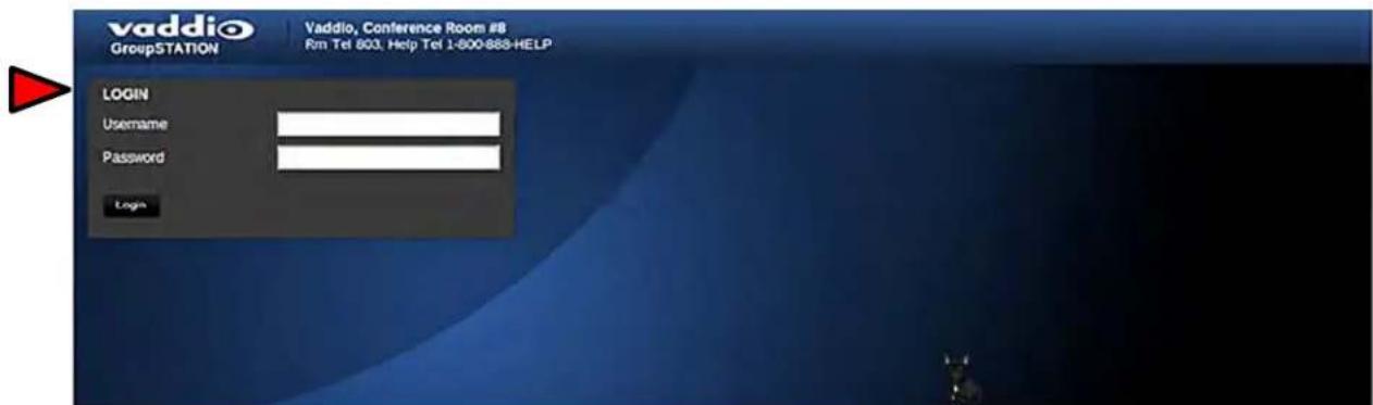
Default Settings:
Admin name is: admin
Password is: password
Screen Shot: Configuration Page
The configuration page allows an administrator to set all the preferences on the GroupSTATION. In addition, the page contains a User Interface replicating functionality of the Dialing Interface on the MicPOD Dock. Other controls include Audio and Video Settings, General Settings, Audio Level and Mute, Video Zoom (19X lens on the Group Station) and Video Mute, PIP on/off and Position

1) VoIP Call Dialing Interface: This dialer essentially replicates the dialing interface on the MicDock allowing a user to launch a VoIP call without being in the room.
2) Audio Controls: The audio volume controls the audio levels through the GroupSTATION speakers. Audio Mute is provided and will mute the mics in the MicDock or the out-going audio.
3) Video Controls: This section controls the zoom range of the camera (the powerful 19X zoom lens), the PIP (picture in picture) on/off and the Video mute function. Video Mute stops sending video of the subjects and will instead send a test pattern or a black screen. The PIP works with the MODE button on the Dock and toggles through the three (3) video operation modes (Presentation, Conference and Normal Modes).
4) Preferences - Audio Settings: The Audio Settings options include:
a. Speaker Bass Boost: EQ filter that enhances the bass response of the GroupSTATION speakers.
b. VoIP TX Boost: Adds a 3dB gain to the transmitted audio channel for the VoIP function.
c. USB TX Boost: Adds a 3dB gain to the USB Record (Microphone Audio) being sent to the PC.
d. HDMI Audio Input Enable: Enable or Disables the HDMI audio input for the MicPOD Dock. When enabled, the HDMI audio will be mixed into the Loudspeaker channels.
5) Preferences - Video Settings: The Video Settings options are as follows:
a. PIP Position: The PIP Position is selected to be in one of the four (4) corners of the main display.
b. Video Mute Pattern: Setting allows the selection between color bars or black screen when a video mute has been enabled from the user interface panel. Video mute applies to the outgoing USB stream and local display.
c. HDMI Output Resolution: The HDMI output resolution from the GroupSTATION Camera/Sound Bar to the Main Monitor is set with this parameter. It has a variety of resolutions and frequencies to fit most applications.
d. Video Input Port: This allows the selection of the RGBHV or the HDMI as the main video source (like the video input button on the front panel of the MicPOD Dock).
6) General Settings:
LINK Cable Length: The system allows use with a supplied 25' (7.62m) or an optional accessory 50' (15.24m). Cat-6 SSTP LINK Cable between the Camera/Sound Bar and the MicPOD Dock. To use the standard 25' cable, put this parameter on 25'. If a 50' cable is used set this parameter to 50'. The cable requirement is stringent and it is recommended that the Vaddio supplied cables be used...More on this later.
Power Mode: Allows the user to put the system to sleep after an idle period, displaying a status message while dozing.
Screen Shot: VoIP SIP Settings
The VoIP configuration menu provides a method for an administrator to configure the SIP user agent and register the device to the SIP Proxy server within the enterprise. The VoIP page is divided into three (3) tabs; Network Settings, SIP Settings and RTP settings.
SIP functionality is disabled by default, use SIP Voice Calls Enabled to enable it. The Transport allows you to set the signaling to TCP, UDP or Auto. The SIP Authentication panel allows an administrator to set the User Name/Extension and password for registration with the SIP server. The User Name/Extension will be the address used by the proxy to route call information. The SIP Outbound Proxy panel provides a method for the Admin to use and configure the user agent to redirect SIP messaging to an outside proxy server that may reside outside the firewall. The Session Timers panel includes the ability to configure sessions and keep alive timers if required for the proxy server. Click on Save to when finished

Screen Shot: VoIP Network Settings
The VoIP network configuration menu allows the administrator to set the configuration properties and the unique IP address for the BaseSTATION. MTU size is adjustable to suit your VOIP networking needs, default setting is 1500. The VLAN section allows the Admin to assign and match the BaseSTATION VoIP configuration parameters to the VLAN that the VoIP traffic uses to ensure the same quality of service (QoS - DSCP) already set-up within the user's voice/data switches. The ID and Priority must match the host network switches if the VLAN is enabled. Please have IT guys provide this information since trial and error, will only yield errors. Click on Save when finished.

Screen Shot: VoIP RTP Settings
The RTP (Real Time Protocol) setting tab allows the administrator to configure the audio streaming function associated with the VoIP user agent.
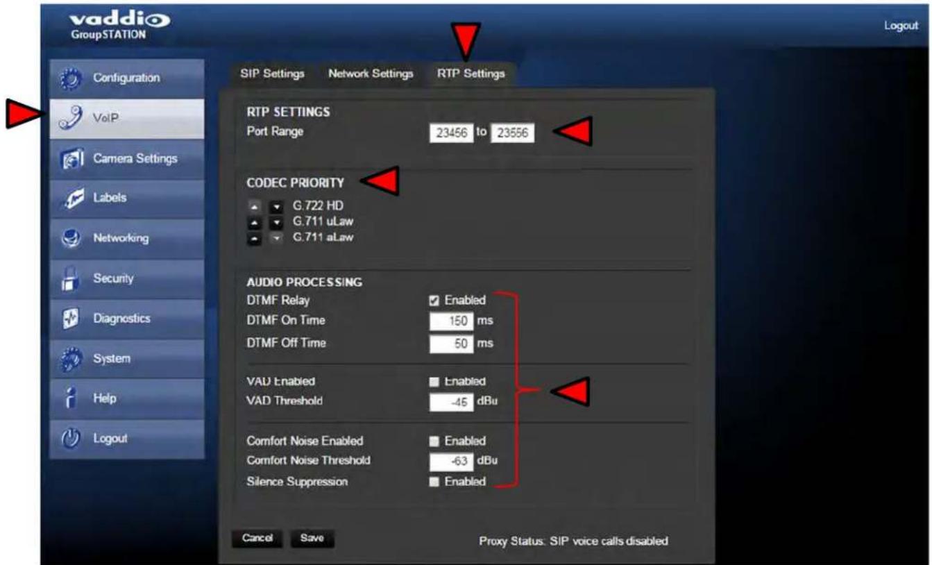
- RTP Port Range: Sets the port range used for audio transports.
- Codec Priority: Allows the administrator to set the priority of audio codec to be used during call negotiations. Available codecs include G.711 μLaw, G.711 aLaw, and G.722. The first in the list will be the preferred codec to be used during the call negotiation. The codec types will change position with the up or down arrows that are next to each setting.
- Audio Processing: Various audio processing functions are available for the VoIP call. This includes ability to enable and set DTMF timing, voice activated detection (VAD) and comfort noise fill (CNF). The default configuration should be adequate in most installations.

Important Note: There is a VoIP Network Worksheet available to assist IT managers and system integrators with installing the GroupSTATION, HuddleSTATION, or BaseSTATION VoIP conferencing platform into the enterprise VoIP system. The worksheet will be available on the Vaddio website. It also is in the back of this riveting manual.
Screen Shot: Camera Controls
The BaseSTATION Camera Module video characteristics can be controlled from this page to prevent shot badness. The Color Settings controls are Auto Iris, Auto White Balance, Detail and Chroma. The Auto Iris mode, when turned off, will present an Iris and Gain control for fine adjustments of the video's exposure. The Auto White Balance, when turned off, will present Red and Blue control sliders for adjustment of the video coloration. For most applications, the Auto functions will be sufficient and should only be used to combat poor lighting or improper background shots, such as all black or all white backgrounds. The Detail control adjusts the sharpness of the image, but too much detail can look grainy. Finally, the chroma control, which adjusts the overall intensity of all the colors in the image. If the image gets too whacked out, a Restore Defaults button can prove useful.

Screen Shot: Room Labels
The Label menu allows the administrator to define the specific room information with the GroupSTATION installation that will be displayed on the webpages. The company and room name, the room phone extension and the Help line phone numbers are displayed.

Screen Shot: DHCP Network
The Networking page is used to configure the GroupSTATION IP addressing (non-VoIP). It supports DHCP or Static IP addresses and a Host Name. It also includes the MAC address associated with the device.

The IP address can also be obtained from the GroupSTATION by pressing and holding the green Answer button on the Dock for 5 seconds. The current IP and MAC address will be displayed for 10 seconds, and then for the next 10 seconds the VoIP IP address and Proxy Status is displayed on the On-Screen-Display (OSD) associated with the HDMI output to the room monitor.
Screen Shot: Static IP Network
To set up the Ethernet Port to Static IP address, click on Static and enter the IP address, the subnet mask and the gateway and click on save. Double check the data prior to clicking save.

Screen Shot: Security
The administrator account has a password for login security. The admin account will always require a password entry for login to the administrator pages on the GroupSTATION. The GroupSTATION ships with a factory default password of: 'password' but can be modified after initial login.

Screen Shot: Diagnostics Menu
The Diagnostics function within the GroupSTATION is intended for advanced troubleshooting. It includes logging capabilities of key events and error reporting during normal operations. The internal logging function is setup as a revolving FIFO with estimated internal storage capabilities for up to one week. SIP logging is also available for SIP call analysis. The administrator has the ability to clear the log or download the log to a local PC.
![vaddio Group STATION Vaddio, Conference Room 8 Rm Tel 803, Help Tel 1.800-555-Help Configuration VoIP Camera Settings Labels Networking Security Diagnostics System Help Logout DIAGNOSTICS Logging Options Link Cable Logging Enabled vaddio-huddle-station [ 2.680000] No device for DAI davinci-i2s vaddio-huddle-station [ 2.700000] No device for DAI fake-codec vaddio-huddle-station [ 2.710000] asoc: fake-codec <-> davinci-i2s mapping ok vaddio-huddle-station [ 3.600000] kjournald starting. Commit interval 5 seconds vaddio-huddle-station [ 3.610000] EXT3 FS on mmcblk0p5, internal journal vaddio-huddle-station [ 3.610000] EXT3-fs: mounted filesystem with writeback data mode. vaddio-huddle-station [ 6.060000] kjournald starting. Commit interval 5 seconds vaddio-huddle-station [ 6.070000] EXT3 FS on mmcblk0p6, internal journal vaddio-huddle-station [ 6.070000] EXT3-fs: mounted filesystem with writeback data mode. vaddio-huddle-station [ 10.180000] CMEMK module: built on Aug 4 2015 at 16:42:47 vaddio-huddle-station [ 10.230000] Reference Linux version 2.6.32 vaddio-huddle-station [ 10.240000] File /var/lib/jenkins/workspace/vrg-release-build/2015-08-04_16-32-02/arago-tmp/work/vaddi vaddio-huddle-station [ 10.370000] CMEM Range Overlaps Kernel Physical - allowing overlap vaddio-huddle-station [ 10.370000] CMEM phys_start (0x86ff1000) overlaps kernel (0x80000000 -> 0x8bd00000) vaddio-huddle-station [ 10.440000] allocated heap buffer 0xd3000000 of size 0x1e0000 vaddio-huddle-station [ 10.520000] heap fallback enabled - will try heap if pool buffer is not available vaddio-huddle-station [ 10.520000] CMEM Range Overlaps Kernel Physical - allowing overlap vaddio-huddle-station [ 10.580000] CMEM phys_start (0x1000) overlaps kernel (0x80000000 -> 0x8bd00000) vaddio-huddle-station [ 10.590000] cmemk initialized vaddio-huddle-station [ 11.470000] EDM/AK module: built on Aug 4 2015 at 16:42:51 vaddio-huddle-station [ 11.476000] Reference Linux version 2.6.32 vaddio-huddle-station [ 11.540000] File /var/lib/jenkins/workspace/vrg-release-build/2015-08-04_16-32-02/arago-tmp/work/vaddi vaddio-huddle-station [ 11.976000] IRQ module: built on Aug 1 2015 at 16:12:54 vaddio-huddle-station [ 11.876777] Reference Linux version 2.6.32 vaddio-huddle-station [ 11.916777] File /var/lib/jenkins/workspace/vrg-release-build/2015-08-04_16-32-02/arago-tmp/work/vaddi vaddio-huddle-station [ 11.946777] IRQ initialized vaddio-huddle-station process-watchdog: fpga-service : Videolnput temperature response invalid 49.99.99.99a a1 93.99.99.99a ff vaddio-huddle-station camera-service : CameraSamsungTechwin connected at input 0 ("version":"1.98","date":"29.99.99.99a ff" vaddio-huddle-station av-stream: starting the audio capture pipeline vaddio-huddle-station av-stream: starting the audio playback pipeline vaddio-huddle-station av-stream: starting the video pipeline vaddio-huddle-station av-stream: starting the hid manager vaddio-huddle-station [ 53.346777] g_webcam_rndis gadget: g_webcam_rmdis ready](/content/2026/05/1126692/images/ca6eaa143dfc354d5cc87382512aaf574eadcbf815ff2d6de46acfc30dd70c38.jpg)
Screen Shot: System Menu
The System menu is intended to display the software versions and to provide for future firmware update operations. The administrator can select the new firmware file from a local or network drive. The 'begin firmware update' button is actuated once desired firmware file is selected. The update process will include user notification of status. The "Show less" option closes down the version detail only. Under System Utilities, the remote Reboot and Restore Factory Settings enable remote admins to restart the system or set the system back to the starting defaults. When rebooting the previous configuration will be lost and the system will have to be re-configured from the start. All the settings will be overwritten and there isn't any go back key, so please be real sure.

Screen Shot: Help Menu
The Help menu provides general information about the GroupSTATION assists the administrator in configuring and programming of the device. The Help also includes information on the current firmware release loaded on the device. Click on the support for product related documentation from the Vaddio website

Updating the GroupSTATION
A product as new and evolutionary as the GroupSTATION and the HuddleSTATION, there will be occasions that new software updates are available. These updates will no doubt contain new features, added functionality, changes and tweaks to make good ideas better, and of course, bug fixes. In an effort to make the updates as painless as possible, these directions are provided. Remember, it is always a “better than good idea” to involve the IT guys to upgrade any device, especially UC devices like the Group, Huddle and Base STATIONS.
Updating Instructions:
1) Download the GroupSTATION software file (image) from the Vaddio Tech Center website located at http://www.vaddio.com/tech-center.php. Do not UNZIP this file. Save the file to a local drive.
2) Log-on to the GroupSTATION administrator web pages. Default username is "admin" and default password is "password" (unless changed by the administrator).
3) Navigate to the Systems tab within the web pages. Press the "Choose File" button and navigate to the GroupSTATION firmware image stored in step 1. Once selected, choose "Begin Firmware Update". The following is an example of updating firmware version 1.0.0 to 1.1.0.

4) After clicking on "Begin Firmware Update..." a confirmation pop-up and warning will be displayed. Please read and completely understand the pop-up warnings as it is easy to lose patience waiting for updates. Please read the warnings regarding the interruption of power below.

Note: The GroupSTATION will not be operational once the firmware update begins. Any end-users in the room will be notified with the On-Screen Display that a firmware update is in process.
5) An update can take up to 20 minutes, the pop-up message window will identify the progress of the update and when it is completed. After the update is complete, the new version can be verified on the Help Menu tab. The version is displayed under System Information.

6) After the update has been completed, it is required to power-cycle the system. Find the power supply for the GroupSTATION and remove cord from the AC power outlet or disconnect the AC side of the 24 VDC power supply for a few seconds. Plug the system back in, turn the power on and the system will boot up with the updated software. After the reboot, the System Information menu will display the new versions of Audio, Video In, Video Out, VoIP and the overall System Revision.
GroupSTATION User Operations
The primary user interface for the GroupSTATION is the dial pad interface on the MicDock in combination with visual feedback from an On-Screen-Display (OSD) associated with the HDMI output that connects to the room's monitor. The dial pad is a capacitive touch interface and includes an audible tone when pressed. A description of the button functions are contained in the table below.
| Button Function Operations | ||
Pc | (Dual Function Button) | This button powers the unit from Standby to a normal ON state.A green LED indication that the GroupSTATION is ready. No LED indicates the unit is in Standby Mode.To enter Standby Mode push and hold the Power button for 3.0 seconds. Standby Mode is indicated on the OSD. |
 | Mute | This button represents a global Mute of all microphones within the GroupSTATION. The four red LEDs will illuminate when the microphones are muted. |
Volum  und Down und Down | The Volume up and down buttons allows the user to increase or decrease the system's loudspeaker audio level. Eight LEDs indicate the current level of the loudspeaker volume. | |
Vide Source | This button toggles the video input source on the MicDock from HDMI to RGBHV. This button is used if multiple video sources are connected to the unit and allows either video input source to be routed to the room's LCD. | |
 OUT OUT | The Zoom IN (+) and Zoom OUT (-) buttons control the camera's 19X optical zoom lens. This button does allow "Press and Hold" capabilities for zooming to the desired field of view. | |
 | PIP/Mode(Multi-purpose Button) | This button enables the PIP/Mode operations for the video sources. The button toggles between three operational Modes: Conference Mode: This mode will create PIP (PC Input + Camera) in the USB stream.Presentation Mode: This mode will create PIP for both the USB stream and the HDMI Output to the room's LCD displayNormal Mode: Disables PIP function. The OSD will display the mode as user toggles through settings. |
 | Answer/Send(Multi-purpose Button) | This button is dual purpose and associated with the VoIP functions.Answer Function: This button is used to answer inbound calls. The LED will start flashing when in-bound call is detected. This also includes audible ringing out the loudspeakers.Send Function: This button is also used for dialing operations. User enters desired number to be dialed. The OSD will display the number to be dialed. Once number is entered, user presses button to Send to establish the call.IP & MAC Address: To display the IP and MAC addresses on the OSD, press and hold this button for 3.0seconds. The IP and MAC addresses will be displayed for 20 seconds. |
 | Hang-Up(Dual-Purpose Button) | This button disconnects a VoIP call. The Red LED flashes once to indicate the call was terminated.For a Factory Reset, push and hold the Hang-up button for 5.0 seconds. The system will provide a prompt on the monitor (Press 5). When the prompt is answered the system will reset. |
Making a VoIP Call
Once the GroupSTATION is registered to the VoIP PBX/SIP Proxy by the network administrator or other qualified IT or phone system personnel, the GroupSTATION functions surprisingly like a typical telephone set.
Step 1: Dial the desired number using the MicDock User Interface. The OSD will automatically pop-up on the room's LCD, at the top of the image, showing the number being dialed.
176349714400
If the number is incorrect, pressing the Hang-up Button will clear the number allowing re-entry.

Step 2: Once the desired number is entered. Press the Send button. The OSD will indicate that a call is trying to be established to the other party.

Dialing
The OSD will display additional messages about the status of the call which includes Busy, Connected, or Error.
Accepting a VoIP Call
Audible and visual indicators will be present with an inbound call. A ringtone will be heard from the loudspeakers. In addition, the OSD will display a message that an inbound call is pending.
Incoming Call
Call Acceptance:
To accept a call the User presses the answer key.

Call Rejection:
The hang-up button can be pressed to reject the call.

Connecting to a PC's Audio
The MicDock can be connected to the PC to extend media functions to the GroupSTATION. This includes extending the Audio Playback and Record associated with the PC to the GroupSTATION via USB. This is accomplished by selecting the GroupSTATION as the USB Playback and Record device in Windows Sound Properties or from within the soft client (Lync, WebEx, Skype, etc.). Go to the control panel/sound/playback and select Vaddio STATION as the default Playback device.
Image: Screen Shot Vaddio STATION Selected for Playback
NOTE: On the playback and recording tabs, the GroupSTATION is referred to as the 'Vaddio STATION'. This is primarily due to the products that will be introduced in 2014 that will use the same fundamental software (i.e. HuddleSTATION etc...).

The GroupSTATION supports HDMI audio and can be selected, alternatively as the default audio playback source. The HDMI audio will be depicted as a Vaddio STATION Monitor within the sound configuration. The sound will still be processed the same way as the selection of the speaker but offers a second audio input with another PC or a tablet with HDMI audio.
Image: Screen Shot Vaddio HDMI Monitor Selected for Playback

Select GroupSTATION as the recording or microphone device within sound panel since the mics in the MicDock are needed for any/all conferencing or recording applications.
Image: Screen Shot Vaddio STATION Selected for recording


Certified Important Note: The GroupSTATION (Vaddio STATION) must be selected as both the Playback (speaker) and Record (microphone) device within Windows or Soft Client for proper Hands-free audio operations.
Selecting GroupSTATION as PC Camera
The GroupSTATION emulates an USB Web Camera to the PC. VaddioSTATION (below) must be selected as the source with any software application. Once the GroupSTATION is connected to the PC via USB, it will be depicted as a camera within the device page within Windows. Alternatively, it will show up as an available source, UVC camera, to any of the soft clients (Lync, WebEx, Skype, etc...).

Extending PC Display to Room's Display
The local PC's display can be extended to the room's large format display by plugging into either the HDMI or RGBHV (VGA) port on the MicPOD Dock. This is equivalent to connecting to a room projector to share the PC's display to the room. Anything on the local PC display can be emulated to the room's display.
Compatibility
The GroupSTATION will work with the following web browsers, soft codecs, computer operating systems and media players:
Compatibility: Web Browsers:
1) Internet Explorer (IE 8 and above)
2) Safari (Rev 4 and 5)
3) Safari/iOS (Rev 4 and 5)
4) Chrome (the latest and current release - auto updating)
5) Firefox (the latest and current release - auto updating)
Soft Clients Compatibility:
GroupSTATION is compatible with the following soft codecs or applications, in no particular order.
| UC Program Operation System Notes | ||
| Skype | Win 7 & Mac OS 10.7 | Mac OS 10.9.x |
| Web Ex | Win 7 & Mac OS X | (WBS 28.7 and up) |
| Microsoft Lync | Win 7 | - |
| Vidyo Desktop | Win 7 & Mac OS X | - |
| Google Plus | Win 7 | - |
| Adobe Connect 8 | Win 7 & Mac OS X | - |
| LifeSize ClearSea | Win 7 | - |
| GoToMeeting (Citrix) Win 7 & Mac OS X | - | |
| Polycom M100 Win 7 | - | |
| Panaopto Win 7, (lecture capture) | Lecture Capture | |
| Zoom | Win 7, Mac OS X | Service Based Program |
Compatibility: Media Players
The UVC with MJPEG video are compatible with the industry leading PC media players.
- Quick-Time 10.2
• VLC Media Player 2.1.0
• Real Player 16.0
Compatibility: Operating Systems
• Apple OS X (10.9.x)
• Windows XP w/Service Pack 3 with known issues and errata
- Windows 7
- Linux
Evolving Compatibilities
As more UC soft-client and lecture capture programs are released and gain popularity, Vaddio will provide a continuing research and development effort to ensure the compatibility with other manufacturer's products.
USB 2.0 MJPEG Resolutions
The USB 2.0 UVC (Universal Video Class) video driver resolution table is an internal list of resolutions available for the Host PC and the GroupSTATION to negotiate and use for any specific application. Typically, the highest resolution possible between both the PC and GroupSTATION is used. However, not all OS and application combinations are typical. Some applications are assigned to a lower value, or the lowest resolution to purposely minimize the bandwidth requirement. In order to avoid selection of the smallest resolution possible, the resolutions of 160 x 120 and 160 x 90 were removed because it looked sort of wicked awful (in some respects).
Table: Supported Resolutions
| Format | Resolution | Frame Rate | Aspect Ratio |
| MJPEG | 1280 x 720 | 15/30 | 16:9 |
| Motion JPEG | 960 x 544 | 15/30 | 16:9 |
| 704 x 576 | 15/30 4:3 | ||
| 640 x 480 | 15/30 4:3 | ||
| 640 x 360 | 15/30 | 16:9 | |
| 424 x 240 | 15/30 4:3 | ||
| 352 x 240 | 15/30 4:3 | ||
| 320 x 240 | 15/30 4:3 | ||
| 320 x 180 | 15/30 | 16:9 |
Warranty Information (See Vaddio Warranty, Service and Return Policies posted on vaddio.com for complete details):
Hardware* Warranty: Two (2) year limited warranty on all parts and labor for Vaddio manufactured products. Vaddio warrants its manufactured products against defects in materials and workmanship for a period of two years from the day of purchase, to the original purchaser, if Vaddio receives notice of such defects during the warranty. Vaddio, at its option, will repair or replace products that prove to be defective. Vaddio manufactures its hardware products from parts and components that are new or equivalent to new in accordance with industry standard practices.
Exclusions: The above warranty shall not apply to defects resulting from improper or inadequate maintenance by the customer, customers applied software or interfacing, unauthorized modifications or misuse, mishandling, operation outside the normal environmental specifications for the product, use of the incorrect power supply, modified power supply or improper site operation and maintenance. OEM products and products manufactured by other companies are excluded and are covered by the manufacturer's warranty.
Vaddio Customer Service: Vaddio will test, repair, or replace the product or products without charge if the unit is under warranty. If the product is out of warranty, Vaddio will test then repair the product or products. The cost of parts and labor charge will be estimated by a technician and confirmed by the customer prior to repair. All components must be returned for testing as a complete unit. Vaddio will not accept responsibility for shipment after it has left the premises.
Vaddio Technical Support: Vaddio technicians will determine and discuss with the customer the criteria for repair costs and/or replacement. Vaddio Technical Support can be contacted through one of the following resources: e-mail support at support@vaddio.com or online at vaddio.com.
Return Material Authorization (RMA) Number: Before returning a product for repair or replacement request an RMA from Vaddio's technical support. Provide the technician with a return phone number, e-mail address, shipping address, product serial numbers, and original purchase order number. Describe the reason for repairs or returns as well as the date of purchase. See the General RMA Terms and Procedures section for more information. RMA's are valid for 30 days and will be issued to Vaddio dealers only. End users must return products through Vaddio dealers. Include the assigned RMA number in all correspondence with Vaddio. Write the assigned RMA number clearly on the shipping label of the box when returning the product. All products returned for credit are subject to a restocking charge without exception.
Voided Warranty: The warranty does not apply if the original serial number has been removed or if the product has been disassembled or damaged through misuse, accident, modifications, use of incorrect power supply, use of a modified power supply or unauthorized repair.
Shipping and Handling: Vaddio will not pay for inbound shipping transportation or insurance charges or accept any responsibility for laws and ordinances from inbound transit. Vaddio will pay for outbound shipping, transportation, and insurance charges for all items under warranty but will not assume responsibility for loss and/or damage by the outbound freight carrier. If the return shipment appears damaged, retain the original boxes and packing material for inspection by the carrier. Contact your carrier immediately.
Products not under Warranty: Payment arrangements are required before outbound shipment for all out of warranty products.
*Vaddio manufactures its hardware products from parts and components that are new or equivalent to new in accordance with industry standard practices.
Other General Information:
Care and Cleaning
Do not attempt to take this product apart at any time. There are no user-serviceable components inside.
- Do not spill liquids in the product
- Keep this device away from food and liquid, especially caviar.
- For smears or smudges on the product, wipe with a clean, soft cloth
- Use a lens cleaner on the lens
- Do not use any abrasive chemicals.
Operating and Storage Conditions:
Do not store or operate the device under the following conditions:
• Temperatures above 40°C (104°F) or temperatures below 0°C (32°F)
• High humidity, condensing or wet environments
• In swimming pools or tadpole pools
• In inclement weather
• Dry environments with an excess of static discharge
• In a rotary evaporator (steam condenser type)
• Under severe vibration
GroupSTATION Compliance and CE Declaration of Conformity
Compliance testing was performed to the following regulations:
FCC 47 CFR Part 15, Subpart B/Oct. 2009 Class A
ICES-003, Issue 4: 2004
EN-55011:2007 + A2: 2007
EN 55022:2006 + A1: 2007 Class A
CISPR 22:1997
IEC 60950-1:2005 (Second Edition); Am 1:2009
EN 60950-1:2006+A11:2009+A1:2010+A12:2011
EMC Directive 2004/108/EC
Class A
Class A

natural_image
Close-up of a black electronic device with a central lens and rectangular body (no visible text or symbols)Class A
Safety
Safety
C
a
s

A

FCC Part 15 Compliance
This equipment has been tested and found to comply with the limits for a Class A digital device, pursuant to Part 15 of the FCC Rules. These limits are designed to provide reasonable protection against harmful interference when the equipment is operated in a commercial environment. This equipment generates, uses, and can radiate radio frequency energy and, if not installed and used in accordance with the instruction manual, may cause harmful interference to radio communications. Operation of this equipment in a residential area is likely to cause harmful interference in which case the user will be required to correct the interference at his/her own expense.
Operation is subject to the following two conditions: (1) This device may not cause interference, and (2) This device must accept any interference including interference that may cause undesired operation of the device.
Changes or modifications not expressly approved by Vaddio can affect emission compliance and could void the user's authority to operate this equipment.

Industry Canada
Industrie Canada
ICES-003 Compliance
This digital apparatus does not exceed the Class A limits for radio noise emissions from digital apparatus set out in the Radio Interference Regulations of the Canadian Department of Communications.
This product has been evaluated for Electromagnetic Compatibility under the standards for Emissions and Immunity and meets the requirements for E4 environment. This product complies with Class A (E4 environment). In a domestic environment this product may cause radio interference in which case the user may be required to take adequate measures.
Standard(s) To Which Conformity Is Declared:
EN-55011:2007 + A2:2007
EN 55022:2006 + A1:2007
EN 61000-6-4:2007
EN 61000-3-2:2006
EN 61000-3-3:2008
EN 61000-6-2:2005
EN 55024:1998 + Amendments A1:2001 + A2: 2003
EN 61000-4-2:2008
EN 61000-4-3:2008
EN 61000-4-4:2004 + Corrigendum 1:2006 + Corr. 2:2007
EN 61000-4-5:2005
EN 61000-4-6:2008
EN 61000-4-8:2009
EN 61000-4-11: Second Edition: 2004
IEC 60950-1:2005 (Second Edition); Am 1:2009
EN 60950-1:2006+A11:2009+A1:2010+A12:2011
Emissions
Conducted
and
Radiated
Electromagnetic Compatibility
Limits for Harmonic Content
Limits for Voltage Fluctuations and Flicker
Immunity for Industrial Environments
Immunity
Electrostatic Discharge
Radiated Immunity
Electrical Fast Transients
Surge
Immunity
Conducted
Immunity
Power
Frequency
Magnetic
Field
Voltage Dips, Interrupts and Fluctuations
Safety
Safety
General Specifications
| GroupSTATION | |
| Part Numbers | GroupSTATION Base System: 999-8800-000 North America, 999-8800-001 Int'lGroupSTATION Deluxe System: 999-8904-000 North America, 999-8904-000 Int'l (with wall mount)GroupSTATION Premier System: 999-8905-000 North America, 999-8905-000 Int'l (with wall mount and 4x4 PC Interface cable) |
| Loudspeaker Pair of 2-Way Speakers and 2X25 Watt Class-D Amplifier | |
| ZoomSHOT Type Cam 720p with 19X motorized optical zoom. Manual Pan/Tilt | |
| VoIP SIP User Agent | |
| Video Output HDMI video output | |
| Video Procession Input switching, On-screen Display, Picture-in-Picture | |
| User Controls MicDock and Internal Web server | |
| Connectors | Network (RJ-45), HDMI (output), Dock LINK (Shielded RJ-45), Power (5.5mm x 2.5mm coax) |
| MicPOD Dock | |
| User Controls | Dialing, Mute & Volume, Zoom, PIP, Video Select, Power On/Off with on screen display of user controls |
| Microphones | 4- Cardioid Condenser, Low Noise Microphone Elements (arranged in 360Degree pattern) |
| Audio Procession | Acoustical Echo Cancellation, Automatic Gain Control, Noise Reduction, Automatic Microphone Mixing, HP/LP Filters |
| Video Input HDMI: | 1080p/60/59.94/50/30/25 frames/s, 720p/60/59.94/50 frames/s, 1080i/59.94/50 fields/sec, 1080i/60DVI (on HDMI w sRGB color space):1080p/60/59.94/50/frames/s, 720p/60/59.94/50Hz frames/s, 1080i/59.94/50Hz, fields/sec, 1440 x 900@60Hz, 1360 x 768@60Hz, 1280 x 800@60 Hz, 1280 x 768@60Hz, 1280 x 720@60Hz, 1152 x 720@60Hz, 1024 x 768@60HzRGBHV:1280 x 720@60Hz (16:9), 1280x768@60Hz (15:9)m, 1280x800@60Hz (16:10), 1360 x 768@60Hz (16:9), 1024 x 768@60Hz (4:3 centered in 16:9 frame) |
| Connectors | USB (micro-B), Network (RJ-45), HDMI (Input), DE-15 (VGA Input), Dock LINK (Shielded RJ-45) |
| General Information | |
| Cat-6 SSTP Cable | 26AWG stranded, individually shielded pairs with overall shield, gold contacts and metal shielded RJ-45Printed on Jacket: Cat-6 26 AWGx4pr SSTP IEC 60332.1, Conforms to ISO/IEC 11801 & EN 50288, ANSI & TIA/EIA-568-C.2 3P/ETL Verified CMX (UL) C(UL) CMH E193793) |
| Operating Temperature | 32° to 104° F (0° to 40° C) / 20% to 80% Relative Humidity |
| Audio Specification | Frequency Response: 20 HZ to 20KHZ, Dynamic Range: >90dB, THD + Noise: <.02% |
| Camera Specification | 1/2.8-Type Exmor Sensor, 19XOptical Zoom, Viewing: 58deg. (wide) to 3.1 deg. (tele) |
| USB Specifications | USB 2.0-UVC and UAC compliant, Video: Up to 720p/30 MJPEG, Audio: Stereo PCM at 48KHZ, 16 bit |
| Dock LINK Interface | Proprietary high speed digital interface with Video, Audio, Control, Network, and Power. Cat-6 SSTP cable with individually shielded pairs. 25' (7.62m) included with every system. 50' (15.24m) Cat-6 SSTP cable with individually shielded pairs sold separately. |
| Power Consumption | <72 Watts |
| Power Supply 24 VDC, 3.0 Amps | |
| Dimensions (H x W x D) | GroupSTATION Camera/Sound Bar : 6.125" (155.58mm) H x 46.12" (1.17m) W x 5.655" (143.64mm) D GroupSTATION MicPOD Dock: 1.699" (43.17mm) H x 9.25" (234.95mm) Diameter (round)Opt. Premium Wall Mount: 6.095" (154.81mm) H x 39.8" (1.01m) W x 2..272" (57.71mm) D (depth of cable tray ) |
| Weight | GroupSTATION: Approximately 19.65 lbs. (8.9130901 kg)Mic Pod Dock: Approx. 1.67 lbs. (0.75749926 kg)Optional Premium Wall Mount: 3.55 lbs. (1.6102529 kg) |
| Accessories | Premium Wall Mounting Kit with Integrated Cable Tray (999-8901-000)4x4 PC Interface Cable for MicDock (999-8902-000)50' Shielded Cat-6 SSTP with Individually Shielded Pairs (999-8903-000) |
| Network Requirements | |
| IP Addresses | For each GroupSTATION, three (3) IP addresses are required:One (1) for the GroupSTATION conferencing and set-up web pagesOne (1) for GroupSTATION VoIPOne (1) for the room PC with the UC application |
| Default IP Address and Ports Used | Group STATION Default IP: 169.254.1.1 & Subnet Mask: 255.255.0.0GroupSTATION VoIP: Port 5060, Typical Browsers: Port 80RTP Settings Default Port Range: 23456 to 23556 (100 ports) for audio transports |
Appendix A: Network Information Required
The intent of this appendix is to assist both A/V system integrators and IT managers preparing for the installation of the GroupSTATION conferencing platform into the enterprise IP and VoIP network.
For the GroupSTATION and room PC, three (3) total IP addresses are required. The addresses are as follows:
1) For the GroupSTATION for UC conferencing
2) For the GroupSTATION VoIP conferencing
3) For the in-room PC used with the UC conferencing application.
For the first GroupSTATION IP address (Non-VoIP):
The GroupSTATION IP address information (for non-VoIP) is entered under the Networking Menu tab. The following items will need to be entered:
1) Hostname: ____. The Hostname is a label used for identification of the Group/HuddleSTATION UC conferencing device connected to the network.
2) Network Type; DHCP or Static. If DHCP, then the address information should auto-fill
3) If Static, then the following information is needed (the MAC address is provided).
IP Address:
Subnet Mask:
Gateway:
For the 2 ^nd GroupSTATION IP Address (VoIP):
The GroupSTATION IP address information for VoIP is entered under the VoIP Menu tab. The following items will need to be entered:
1) Hostname: ____. The Hostname is a label used for identification of the Group/HuddleSTATION VoIP conferencing device connected to the VoIP network.
2) Network Type; DHCP or Static. If DHCP, then the address information should auto-fill
3) If Static, then the following information is needed (the MAC address is provided).
IP Address:
Subnet Mask:
Gateway:
DNS Server:
4) VLAN: The following Information is required if the Host site uses segmented VoIP and data to prioritize VoIP over data traffic on the LAN/WAN (essentially the network QoS - the car pool lane for VoIP).
☐ VLAN Enabled (If enabled then ID and User Priority are required)
ID#: ____ User Priority#: ____
Under the SIP Settings Tab the following information must be entered under the headings SIP Authentication, SIP Outbound Proxy and Session Timers:
• SIP AUTHENTICATION
User Name/Extension (User Name/Extension is used by the SIP Server to route calls): ____
Password (Password authentication to the SIP server): ____
Display Name (Acts as caller ID for the call destination): ____
User Domain (SIP IP address or Domain Name):
Authentication User Name (Authenticate to LDAP or some web based services): ____
Local SIP Port (Default Port is 5060):
• SIP OUTBOUND PROXY
Proxy/URL Address (Address for SIP Outbound Proxy Server): ____
Proxy Port (Default Port is 5060): ____
- SESSION TIMERS
Registration Lifetime (Default is 3600 sec):
Keep Alive Timer (Click to Enable - Enter Timer Value - Default is 30 sec):
Under the RTP Settings Tab the RTP Port Range, the Codec Priority and the Audio Processing parameters are defined. The following information is required for the RTP Settings tab:
- RTP SETTINGS
Port Range: (Sets RTP port range used for audio transports)
• CODEC PRIORITY
☐ G.722 HD - Wideband ☐ G.711μLaw ☐ G.711aLaw (The first in the list will be used for call negotiation)
• AUDIO PROCESSING
DTMF Relay: ☐ (For using DTMF in band - Click to Enable)
DTMF ON Time: (Default 150ms 0 - Sets DTMF timing)
DTMF OFF Time: (Default 50ms - Sets DTMF timing)
VAD Enabled: ☐ (Check to Enable - Voice Activity Detection) Used for bandwidth management.
VAD Threshold: (Default -45dBu - minimum level that voice has to be in order to be detected)
Comfort Noise Enabled: ☐ (Check to Enable) Synthetic background noise used to fill the artificial silence of digital
Comfort Noise Threshold: (Default -63dBu)
Silence Suppression: ☐ (Check to Enable - With VAD on, Silence Suppression works to reduce call bandwidth when no voice is detected)
(In most cases, the defaults should be adequate.)
For the 3 ^rd GroupSTATION IP Address (PC):
The 3 ^rd and final IP Address is for the in-room PC or laptop (BYOD) that is running the chosen UC application. The courtesy network jack on the MicDock can be used by the room PC, or any other network jack in the room that is on the same network as the GroupSTATION.

As always, it is very important from to work closely with the IT professionals at the place of installation to acquire the IP addresses, the required VoIP information and the network jack(s) required to install and operate each GroupSTATION.
System Configuration Notes:
vaddio
Vaddio, Toll Free: 800-572-2011 · Phone: 763-971-4400 · FAX: 763-971-4464, vaddio.com
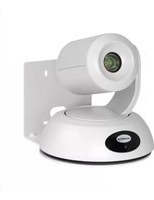
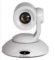
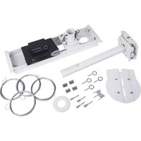
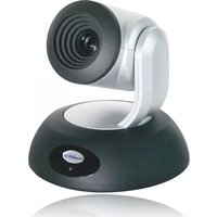
- Group Collaboration Appliance
- Part Numbers:
- Accessories
- Table of Contents
- Overview
- Intended Use:
- Important Safeguards:
- Installation Requirements
- Save These Instructions
- Unpacking
- GroupSTATION Base System 999-8900-000 (North America)
- GroupSTATION Base System 999-8900-001 (International)
- GroupSTATION Options/Accessories
- GroupSTATION Wall Mounting Kit (Worldwide)
- GroupSTATION PC to MicDock Interface Cable
- GroupSTATION System Packages
- Group Station Deluxe System with Premium Wall Mount Included Part Number: 999-8904-000 (North America)
- Group Station Deluxe System with Premium Wall Mount Included Part Number: 999-8904-001 (International)
- GroupSTATION Premier System with Premium Wall Mount and PC to Dock Interface Cable Included Part Number: 999-8905-000 (North America)
- GroupSTATION Premier System with Premium Wall Mount and PC to Dock Interface Cable Included Part Number: 999-8905-001 (International)
- Other GroupSTATION Accessory Options
- Anatomy of the GroupSTATION MicPOD Dock Image: MicDock User Interface with Call-outs
- First Time Set-up with the GroupSTATION
- Installation Instructions:
- Step 1: Position the GroupSTATION Camera/Sound Bar
- Step 1: (continued)
- Step 2: Route Cables in Cable Tray
- Step 3: Hang the Camera/Sound Bar on the Wall Bracket
- Diagram: Rear of the Camera/Sound Bar showing the location of the Z-Clips
- Diagrams: Mounting the Z-Clips on the Z-Channel
- Step 4: Connecting the MicPOD Dock
- Step 5: Docking the PC to MicPOD Dock
- Cables required:
- Option: Using the PC to MicDock Accessory Cable:
- Step 6: Initial System Power Up
- Image: Press and Hold Multifunction Buttons (PHMB)
- 1) Answer (Send) Button:
- 2) Hang-up (Disconnect Button):
- 3) On/Off Power Butt
- System Configuration and Programming
- Network Requirements and Information
- Accessing the GroupSTATION Web Pages
- • DHCP IP Set-up (Dynamic Host Configuration Protocol)
- - Static IP Set-up:
- GroupSTATION Web Page Tour
- Screen Shot: Login
- Default Settings:
- Admin name is: admin
- Password is: password
- Screen Shot: Configuration Page
- Screen Shot: VoIP SIP Settings
- Screen Shot: VoIP Network Settings
- Screen Shot: VoIP RTP Settings
- Screen Shot: Camera Controls
- Screen Shot: Room Labels
- Screen Shot: DHCP Network
- Screen Shot: Static IP Network
- Screen Shot: Security
- Screen Shot: Diagnostics Menu
- Screen Shot: System Menu
- Screen Shot: Help Menu
- Updating the GroupSTATION
- Updating Instructions:
- GroupSTATION User Operations
- Making a VoIP Call
- 176349714400
- Dialing
- Accepting a VoIP Call
- Incoming Call
- Call Acceptance:
- Call Rejection:
- Connecting to a PC's Audio
- Selecting GroupSTATION as PC Camera
- Extending PC Display to Room's Display
- Compatibility
- Compatibility: Web Browsers:
- Soft Clients Compatibility:
- Compatibility: Media Players
- Compatibility: Operating Systems
- Evolving Compatibilities
- USB 2.0 MJPEG Resolutions
- Other General Information:
- Care and Cleaning
- Operating and Storage Conditions:
- GroupSTATION Compliance and CE Declaration of Conformity
- FCC Part 15 Compliance
- ICES-003 Compliance
- Standard(s) To Which Conformity Is Declared:
- Appendix A: Network Information Required
- For the first GroupSTATION IP address (Non-VoIP):
- For the 2 nd GroupSTATION IP Address (VoIP):
- • SIP AUTHENTICATION
- • SIP OUTBOUND PROXY
- - SESSION TIMERS
- - RTP SETTINGS
- • CODEC PRIORITY
- • AUDIO PROCESSING
- For the 3 rd GroupSTATION IP Address (PC):
- System Configuration Notes:
Brand : Vaddio
Model : Groupstation Premier System
Category : Video Conferencing System