NA111PN - Uncategorized PANASONIC - Free user manual and instructions
Find the device manual for free NA111PN PANASONIC in PDF.

User questions about NA111PN PANASONIC
0 question about this device. Answer the ones you know or ask your own.
Ask a new question about this device
Download the instructions for your Uncategorized in PDF format for free! Find your manual NA111PN - PANASONIC and take your electronic device back in hand. On this page are published all the documents necessary for the use of your device. NA111PN by PANASONIC.
USER MANUAL NA111PN PANASONIC
Small / Slim Object Detection Area Sensor
NA1-11
Related Information
■ General terms and conditions..... P.1
■ Glossary of terms..... P.983\~
■ Sensor selection guide ..... P.11\~ / P.727\~
■ General precautions ...... P.986\~

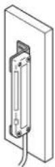
natural_image
Two industrial control panel devices with red and gray components, displayed against a plain background (no text or symbols on the devices themselves)


Make sure to use light curtains when using a sensing device for personnel protection. Refer to p.477\~ for light curtains.

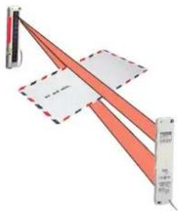
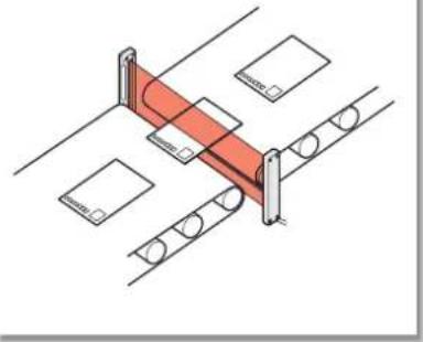
Cross-beam scanning system to detect slim objects
Letter or visiting card detectable!
Slim objects can be detected by using the cross-beam scanning system.
natural_image
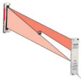
Pure diagram of a red triangular structure with dashed lines and a vertical bar, no text or symbols present.Emitting and receiving element pitch: 10 mm 0.394 in
A minimum sensing object size of 13.5 mm 0.531 in is realized by using an emitting and receiving element pitch of 10 mm 0.394 in.
natural_image
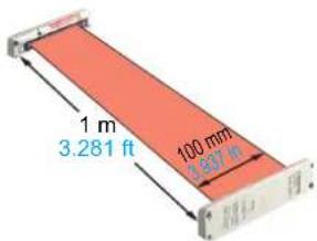
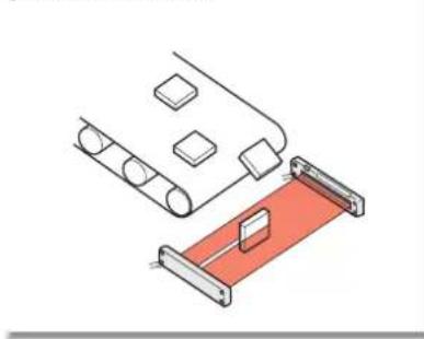
Diagram of a mechanical or structural assembly with orange triangular elements and a vertical bar (no text or symbols)Wide area
Though being very slim, it realizes a wide sensing area of 1 m 3.281 ft length and 100 mm 3.937 in width. It is most suitable for object detection on a wide assembly line, or for detecting the dropping of, or incursion by, small objects whose travel path is uncertain.
text_image
1 m 3.281 ft 100 mm 3.637 ftJust 10 mm 0.394 in thick
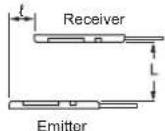
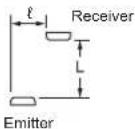
It is extremely slim, being just 10 mm 0.394 in thick. Further, it can be mounted in a narrow space since you can select from two cable orientation directions.
text_image
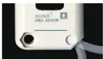
SUNX AREA SENSORIt is possible to select from two cable orientation directions.
Globally useable
It conforms to the EMC Directive and has UL Recognition. Moreover, PNP output type, which is much in demand in Europe, is also available.

ORDER GUIDE
P.765
SPECIFICATIONS
P.766
I/O CIRCUIT DIAGRAMS
P.767
SENSING CHARACTERISTICS
P.767\~
PRECAUTIONS FOR PROPER USE
P.768\~
DIMENSIONS
P.769\~
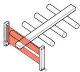
APPLICATIONS
Detecting post-cards Detecting falling objects whose path is uncertain
natural_image
Diagram of a red structural beam supported by two vertical supports, with circular elements and support frames (no text or symbols)path is uncertain
natural_image
Technical illustration of a mechanical assembly with rollers and a red clamping device (no text or symbols)Detecting edge of moving object
natural_image
Pure mechanical assembly diagram showing a ladder with pulleys and a central shaft (no text or symbols)
WARNING
Never use this product in any personnel safety application.
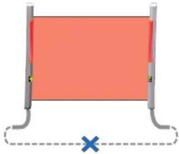
No synchronization wire
Wiring is saved and made simple as no synchronization wire is required between the emitter and the receiver.
natural_image
Simple diagram of a rectangular object with a red fill and two vertical supports, connected by a dashed line with a blue X at the bottom (no text or symbols)Clearly visible indicator
A clearly visible large indicator, having a 55 mm 2.165 in width, is incorporated on both the emitter and the receiver. Further, if the sensing output is directly connected to the large indicator input, the indicator can be conveniently used as a large operation indicator. Moreover, its operation can be selected as lighting or blinking.
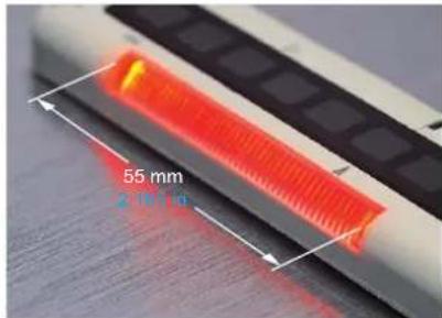
text_image
55 mm 2.10 µmCross-beam Scanning System
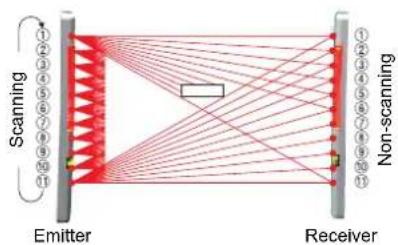
In a conventional area sensor, slim objects cannot be detected since the emitting and the receiving elements are scanned, synchronously, as a set. In contrast, in NA1-11, only the elements ① to ⑪ of the emitter are scanned to obtain emission. The elements of the receiver are not scanned, so that when element ① of the emitter emits light, all the elements of the receiver receive light. Hence, even if there is one element on the receiver which does not receive light, it results in light interrupted operation. With this technique, detection of slim objects is possible.
Conventional area sensor

flowchart
graph TD
    A["Scanning"] --> B["ReceiverEmitter"]
    B --> C["1"]
    B --> D["2"]
    B --> E["3"]
    B --> F["4"]
    B --> G["5"]
    C --> H["1"]
    D --> I["2"]
    E --> J["3"]
    F --> K["4"]
    G --> L["5"]
NA1-11
flowchart
graph TD
    subgraph Emitter
        A1["1"] --> B1["2"]
        A2["3"] --> B2["4"]
        A3["5"] --> B3["6"]
        A4["7"] --> B4["8"]
        A5["9"] --> B5["10"]
        A6["11"] --> B6["12"]
    end
    subgraph Receiver
        C1["1"] --> D1["2"]
        C2["3"] --> D2["4"]
        C3["5"] --> D3["6"]
        C4["7"] --> D4["8"]
        C5["9"] --> D5["10"]
        C6["11"] --> D6["12"]
    end
    Emitter --> Receiver
    Receiver --> NonScanning
    NonScanning --> Scanning
    Scanning --> Emitter
    Scanning --> Receiver
FIBER SENSORS
LASER SENSORS
PHOTOELECTRIC SENSORS
MICRO PHOTOELECTRIC SENSORS
AREA SENSORS
SAFETY COMPONENTS
PRESSURE SENSORS
INDUCTIVE PROXIMITY SENSORS
PARTICULAR USE SENSORS
SENSOR OPTIONS
WIRE-SAVING SYSTEMS
MEASUREMENT SENSORS
STATIC CONTROL DEVICES
LASER MARKERS
Selection Guide Wafer Detection
M-DW1
HD-T1
Liquid Leak Detection
EX-F70 / EX-F60
Liquid Level Detection
EX-F1
Color Mark Detection
LX-100
FZ-10
Small / Slim Object Detection
NA1-11
Metal-sheet Double-feed Detection
GD
Other Products
ORDER GUIDE
| Type Appearance Sensing range (Note1) Model | No.(Note2) Output | |||
| NPN output | 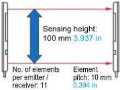 | NA1-11 | NPN open-collector transistor | |
| 5 m 16.404 ft cable length | NA1-11-C5 | |||
| PNP output | NA1-11-PN | PNP open-collector transistor | ||
Notes: 1) The sensing range is the possible setting distance between the emitter and the receiver. The sensor can detect an object less than 0.17m0.558 ft away.
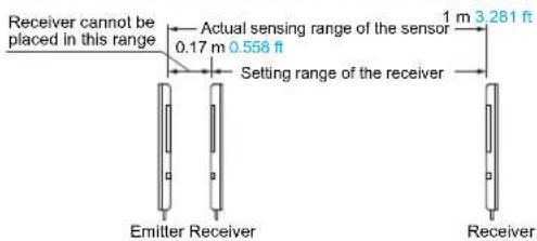
text_image
Receiver cannot be placed in this range Actual sensing range of the sensor 0.17 m 0.558 ft Setting range of the receiver 1 m 3.281 ft Emitter Receiver Receiver2) The model No. with suffix "P" shown on the label affixed to the product is the emitter, "D" shown on the label is the receiver. (e.g.) Emitter of NA1-11: NA1-11P, Receiver of NA1-11: NA1-11D
OPTIONS
| Designation Model No. Description | ||
| Sensor mounting bracket | MS-NA1-1 | Four bracket set{ Four M4 (length 15 mm 0.591 in) screws with washers, eight nuts, four hooks, four spacers and eight M4 (length 18 mm 0.709 in) screws with washers are attached.(Spacers are not attached with MS-NA1-1.)} |
| MS-NA2-1 | ||
Sensor mounting bracket
MS-NA1-1•

M4 screws with washers, nuts and hooks are attached.
MS-NA2-1•

M4 screws with washers, nuts, hooks and spacers are attached.

SPECIFICATIONS
| Type | NPN output PNP output | ||
| Item Model No. NA1-11 NA1-11-PN | |||
| Sensing height 100 mm 3.937 in | |||
| Sensing range (Note 2) 0.17 to 1 m 0.558 to 3.281 ft | |||
| Element pitch 10 mm 0.394 in | |||
| Number of emitting / receiving elements | 11 Nos. each on the emitter and the receiver, respectively | ||
| Sensing object ø13.5 mm | ø0.531 in or more opaque object (Note 3) | ||
| Supply voltage 12 to 24 V DC ± 10 % Ripple P-P 10 % or less | |||
| Current consumption Emitter: 80 mA or less, Receiver: 100 mA or less | |||
| Output | NPN open-collector transistor• Maximum sink current: 100 mA• Applied voltage: 30 V DC or less (between output and 0 V)• Residual voltage: 1 V or less (at 100 mA sink current)0.4 V or less (at 16 mA sink current) | PNP open-collector transistor• Maximum source current: 100 mA• Applied voltage: 30 V DC or less (between output and +V)• Residual voltage: 1 V or less (at 100 mA source current)0.4 V or less (at 16 mA source current) | |
| Output operation ON or OFF when beam channel is interrupted, selectable by operation mode switch | |||
| Short-circuit protection Incorporated | |||
| Response time | In Dark state: 5 ms or less, In Light state: 10 ms or less | ||
| Indicators | Emitter | Power indicator: Green LED (lights up when the power is ON)Large indicator: Orange LED (lights up or blinks when the large indicator input is Low, lighting pattern is selected by operation mode switch) | Power indicator: Green LED (lights up when the power is ON)Large indicator: Orange LED (lights up or blinks when the large indicator input is High, lighting pattern is selected by operation mode switch) |
| Receiver | Operation indicator: Orange LED (lights up when the output is ON)Power indicator: Green LED (lights up when the power is ON)Large indicator: Orange LED (lights up or blinks when the large indicator input is Low, lighting pattern is selected by operation mode switch) | Operation indicator: Orange LED (lights up when the output is ON)Power indicator: Green LED (lights up when the power is ON)Large indicator: Orange LED (lights up or blinks when the large indicator input is High, lighting pattern is selected by operation mode switch) | |
| Environmental resistance | Pollution degree | 3 (Industrial environment) | |
| Protection IP62 (IEC) (Refer to p.984 for details of standards) | |||
| Ambient temperature | -10 to 55 °C +14 to +131 °F (No dew condensation or icing allowed), Storage: -20 to +70 °C -4 to +158 °F | ||
| Ambient humidity | 35 to 85 % RH, Storage: 35 to 85 % RH | ||
| Ambient illuminance | Incandescent light: 3,000 ℓx at the light-receiving face | ||
| EMC | EN 60947-5-2 | ||
| Voltage withstandability | 1,000 V AC for one min. between all supply terminals connected together and enclosure | ||
| Insulation resistance | 20 MΩ, or more, with 250 V DC megger between all supply terminals connected together and enclosure | ||
| Vibration resistance | 10 to 150 Hz frequency, 1.5 mm 0.059 in amplitude in X, Y and Z directions for two hours each | ||
| Shock resistance | 500 m/s2 acceleration (50 G approx.) in X, Y and Z directions for three times each | ||
| Emitting element | Infrared LED (Peak emission wavelength: 880nm 0.035mil, cross-beam scanning system) | ||
| Material | Enclosure: Heat-resistant ABS, Lens: Acrylic, Indicator cover: Acrylic | ||
| Cable | 0.3 mm2 4-core (emitter: 3-core) oil resistant cabtyre cable, 2 m 6.562 ft long | ||
| Cable extension | Extension up to total 100 m 328.084 ft is possible, for both emitter and receiver, with 0.3 mm2, or more, cable. | ||
| Weight | Net weight: Emitter 80 g approx., Receiver 85 g approx, Gross Weight: 210 g approx. | ||
Notes: 1) Where measurement conditions have not been specified precisely, the conditions used were an ambient temperature of +23 °C +73.4 °F.
2) The sensing range is the possible setting distance between the emitter and the receiver. The sensor can detect an object less than 0.17 m 0.558 ft away.
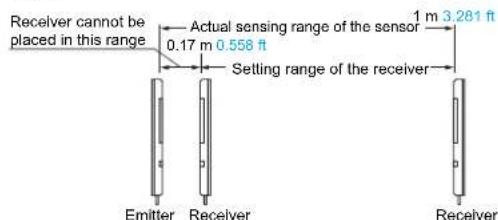
text_image
Receiver cannot be placed in this range Actual sensing range of the sensor 0.17 m 0.558 ft Setting range of the receiver 1 m 3.281 ft Emitter Receiver Receiver3) Although this product can detect slim objects by using the cross-beam scanning system, the size of the slim object which can be stably detected differs with the setting distance. When this sensor is used to detect slim objects, make sure to confirm stable detection using the actual objects.
I/O CIRCUIT AND WIRING DIAGRAMS
NA1-11
NPN output type
I/O circuit diagram
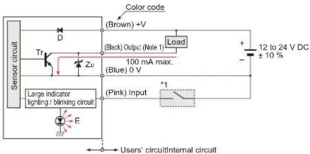
text_image
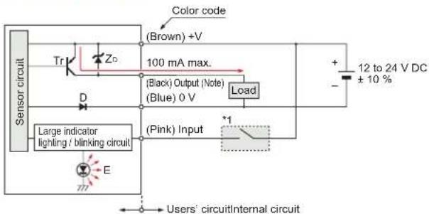
Sensor circuit Color code (Brown) +V (Black) Output (Note 1) Load + 12 to 24 V DC ± 10 % Tr Zv 100 mA max. (Blue) 0 V Large indicator lighting / blinking circuit (Pink) Input *1 E Users' circuitInternal circuitNotes: 1) The emitter does not incorporate the output (black).
2) Unused wires must be insulated to ensure that they do not come into contact with wires already in use.
Symbols ... D : Reverse supply polarity protection diode
ZD: Surge absorption zener diode
Tr: NPN output transistor
E : Large indicator (INDICATOR)
Wiring diagram

text_image
Color code Brown Load Black (Note 1) Blue Pink *1 + 12 to 24 V DC ± 10 %*1
Non-voltage contact or NPN open-collector transistor
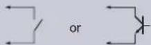
- Input
Low (0 to 2 V): Lights up or blinks
High (5 to 30 V, or open): Lights off
Notes: 1) The emitter does not incorporate the black lead wire.
2) Unused wires must be insulated to ensure that they do not come into contact with wires already in use.
NA1-11-PN
PNP output type
I/O circuit diagram
flowchart
graph TD
    A["Sensor circuit"] --> B["Tr"]
    B --> C["Zo"]
    C --> D["100 mA max."]
    D --> E["(Black) Output (Note)"]
    E --> F["(Blue) 0 V"]
    F --> G["Load"]
    G --> H["+ 12 to 24 V DC ±10%"]
    I["Large indicator lighting / blinking circuit"] --> J["E"]
    J --> K["777"]
    K --> L["Users' circuitInternal circuit"]
    M["Color code"] --> N["(Brown) +V"]
    O["Load"] --> P["*1"]
Notes: 1) The emitter does not incorporate the output (black).
2) Unused wires must be insulated to ensure that they do not come into contact with wires already in use.
Symbols ... D : Reverse supply polarity protection diode
ZD: Surge absorption zener diode
Tr: PNP output transistor
E : Large indicator (INDICATOR)
Wiring diagram

text_image
Color code Brown Black (Note 1) Blue Load + 12 to 24 V DC ± 10 % Pink *1*1
Non-voltage contact or PNP open-collector transistor
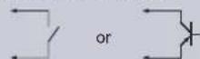
- Input
Low (4 V or more): Lights up or blinks
High (0 to 0.6 V, or open): Lights off
Notes: 1) The emitter does not incorporate the black lead wire.
2) Unused wires must be insulated to ensure that they do not come into contact with wires already in use.
SENSING CHARACTERISTICS (TYPICAL)
Correlation between setting distance and excess gain
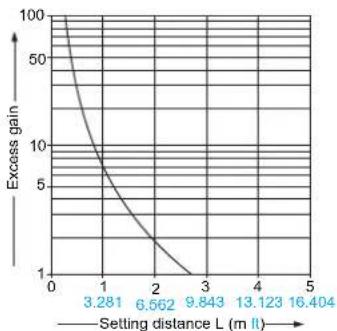
line
| Setting distance L (m ll) | Excess gain | | ------------------------- | ----------- | | 3.281 | 100 | | 6.562 | 10 | | 9.843 | 1 | | 13.123 | 1 | | 16.404 | 1 |SENSING CHARACTERISTICS (TYPICAL)
Parallel deviation
Vertical direction
Horizontal direction
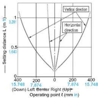
line
| Operating point t (mm in) | Setting distance L (m l) | | ------------------------- | ------------------------ | | 15.748 | 3.281 | | 7.874 | 0.5 | | 0 | 0 | | 7.874 | 0.5 | | 15.748 | 1 |Angular deviation
Emitter angular deviation
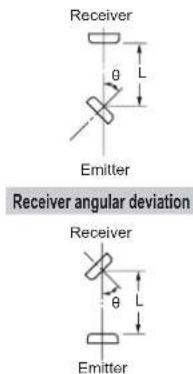
text_image
Receiver θ L Emitter Receiver angular deviation Receiver θ L Emitter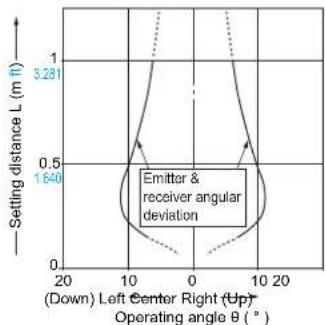
line
| Operating angle B (°) | Setting distance L (m ft) | | --------------------- | ------------------------- | | 0 | 3.281 | | 10 | 1.640 | | 20 | 0 |Correlation between setting distance and minimum length of detectable object
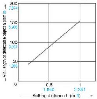
line
| Setting distance L (m ft) | Min. length of detectable object a (mm in) | | ------------------------- | ------------------------------------------ | | 0 | 1.969 | | 1.640 | 3.937 | | 3.281 | 5.906 | | 7.874 | 7.874 |The minimum length of the detectable object, which lies in a plane perpendicular to the sensor front surface, varies with the setting distance, as shown in the left graph. However, note that the minimum length of the detectable object also varies with the object thickness.
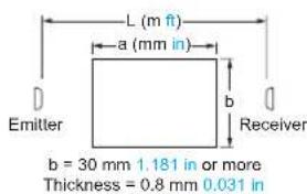
text_image
L (m ft) a (mm in) b Receiver b = 30 mm 1.181 in or more Thickness = 0.8 mm 0.031 in* The sensing object is considered to be placed at the center of the sensing area.
PRECAUTIONS FOR PROPER USE
Refer to p.986 \~ for general precautions.

- Never use this product as a sensing device for personnel protection.
- For sensing devices to be used as safety devices for press machines or for personnel protection, use products which meet laws and standards, such as OSHA, ANSI or IEC etc., for personnel protection applicable in each region or country.
- If this product is used as a sensing device for personnel protection, death or serious body injury could result.
- For a product which meets safety standards, use the following products.
Type 4: SF4B series (P.481\~)
Type 2: SF2B series (P.515\~)
Mounting
- Use M4 screws with washers and M4 nuts. The tightening torque should be 0.5 N·m or less. (Please arrange the screws and nuts separately.)
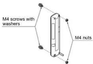
text_image
M4 screws with washers M4 nutsSelection of large indicator operation
- Lighting / Blinking is selected by the operation mode switch on the emitter and the receiver.
| Operation of large indicator | Operation mode switch | |
| Emitter Receiver | ||
| Lighting | ||
| Blinking | ||
Selection of output operation
- The output operation mode is selected by the operation mode switch on the receiver.
The switches must be set with the power supply off. The operation mode does not change if the switch setting is changed with the power supplied.
| Operation mode switch (Receiver) | Output operation | Operation indicator (Orange) | |
| D-ON | ON in Dark state | Lights up when the output is ON | |
| L-ON | OFF in Dark state | Lights up when the output is ON | |
Note: LIGHT / BLINK switch is not related to the output operation selection.
PRECAUTIONS FOR PROPER USE
Refer to p.986 \~ for general precautions.
Others
- Do not use during the initial transient time (0.5 sec.) after the power supply is switched on.
- Although this sensor can detect slim objects by using the cross-beam scanning system, the size of the slim object which can be stably detected differs with the setting distance. Hence, when the sensor is used to detect slim objects, make sure to confirm stable detection using the actual objects.
- In case of this sensor, light from the emitter spreads above and below the sensor. Hence, take care that if there is a reflective object above or below the sensor it will affect the sensing.
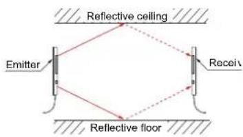
text_image
Reflective ceiling Emitter Receiv Reflective floor* Refer to "Parallel deviation" on p.768.
DIMENSIONS (Unit: mm in) The CAD data in the dimensions can be downloaded from the SUNX website: http://www.sunx.com
NA1-11 NA1-11-PN
Sensor
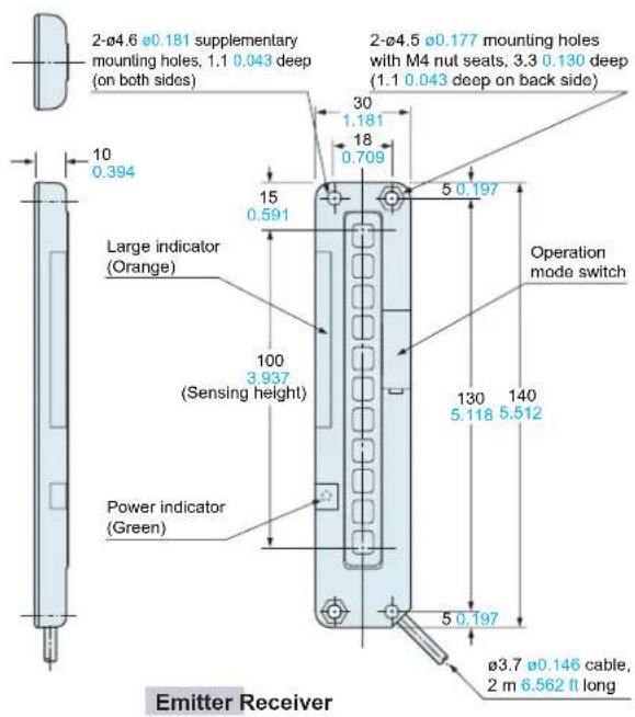
text_image
2-ø4.6 ø0.181 supplementary mounting holes, 1.1 0.043 deep (on both sides) 10 0.394 Large indicator (Orange) 15 0.591 100 3.937 (Sensing height) Power indicator (Green) 2-ø4.5 ø0.177 mounting holes with M4 nut seats, 3.3 0.130 deep (1.1 0.043 deep on back side) 30 1.181 18 0.709 5 0.197 Operation mode switch 130 140 5.118 5.512 5 0.197 ø3.7 ø0.146 cable, 2 m 6.562 ft long Emitter Receiver
text_image
2-ø4.5 ø0.177 mounting holes with M4 nut seats, 3.3 0.130 deep (1.1 0.043 deep on back side) Operation mode switch 140 130 5.512 5.118 5 0.197 30 1.181 18 0.709 15 0.591 Large indicator (Orange) 100 3.937 (Sensing height) Power indicator (Green) Operation indicator (Orange) ø3.7 ø0.146 cable, 2 m 6.562 ft long 2-ø4.6 ø0.181 supplementary mounting holes, 1.1 0.043 deep (on both sides) 10 0.394DIMENSIONS (Unit: mm in)
The CAD data in the dimensions can be downloaded from the SUNX website: http://www.sunx.com
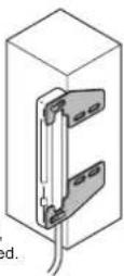
MS-NA1-1
Sensor mounting bracket (Optional)
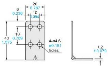
text_image
6 0.236 20 0.787 10 0.394 18 40 1.575 0.709 4-Ø4.6 Ø0.181 holes t 2 t 0.079Material: Cold rolled carbon steel (SPCC) (Uni-chrome plated)
Four bracket set
Four M4 (length 15 mm 0.591 in) screws with washers, eight nuts, four hooks and eight M4 (length 18 mm 0.709 in) screws with washers are attached.
M4 (length 18 mm 0.709 in) screws with washers are not used for NA1-11.
Assembly dimensions
Mounting drawing with the receiver

text_image
2-M4 screws with washers 2-hooks 40 1.575 30 1.181 18 0.709 2-M4 nuts 5 0.197 25 0.984 10 0.394 32 1.260 20 0.787 6 0.236 4.6 10 0.181 0.394 15 0.591 140 130 5.512 5.118 100 ( Sensing ) height 110 4.331 4.6 10 0.181 0.394Sensor mounting bracket (Optional)
MS-NA2-1
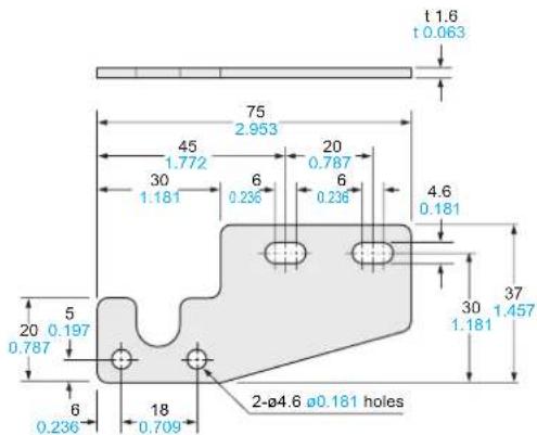
text_image
t 1.6 t 0.063 75 2.953 45 1.772 20 0.787 30 1.181 6 0.236 6 0.236 4.6 0.181 30 1.181 37 1.457 5 20 0.197 0.787 6 0.236 18 0.709 2-Ø4.6 Ø0.181 holesMaterial: Cold rolled carbon steel (SPCC) (Uni-chrome plated)
Four bracket set
Four M4 (length 15 mm 0.591 in) screws with washers, eight nuts, four hooks, four spacers and eight M4 (length 18 mm 0.709 in) screws with washers are attached.
Mounting drawing with the receiver
Assembly dimensions