Large Advantage Deluxe Electrol 36861 - Projection screen DA-LITE - Free user manual and instructions
Find the device manual for free Large Advantage Deluxe Electrol 36861 DA-LITE in PDF.

| Product Type | Projection Screen |
| Brand | Da-Lite |
| Model | Large Advantage Deluxe Electrol 36861 |
| Category | Motorized Projection Screen |
| Screen Type | Electric Motorized |
| Aspect Ratio | 16:9 |
| Screen Gain | 1.0 |
| Viewing Angle | 180 degrees |
| Diagonal Size | 120 inches (approx.) |
| Width | 104.6 inches |
| Height | 58.9 inches |
| Weight | 55 lbs (approx.) |
| Motor Type | Quiet electric motor |
| Power Supply | 120V AC, 60Hz |
| Control Method | IR remote, wall switch (optional) |
| Casing Color | White |
| Mounting Options | Ceiling or wall mount brackets included |
| Screen Material | Matte white vinyl |
| Care Instructions | Clean with soft dry cloth; do not use chemicals |
| Warranty | 2 years limited |
Frequently Asked Questions - Large Advantage Deluxe Electrol 36861 DA-LITE
User questions about Large Advantage Deluxe Electrol 36861 DA-LITE
0 question about this device. Answer the ones you know or ask your own.
Ask a new question about this device
Download the instructions for your Projection screen in PDF format for free! Find your manual Large Advantage Deluxe Electrol 36861 - DA-LITE and take your electronic device back in hand. On this page are published all the documents necessary for the use of your device. Large Advantage Deluxe Electrol 36861 by DA-LITE.
USER MANUAL Large Advantage Deluxe Electrol 36861 DA-LITE
The Da-Lite Difference.

natural_image
Monochrome image of a reflective globe with grid lines, showing continents and oceans (no text or symbols)
natural_image
Blank rectangular image with a flat top and black border, no visible text or symbols.Instruction Book for
3100 North Detroit Street
Post Office Box 137
Warsaw, Indiana 46581-0137
Phone: 574-267-8101
800-622-3737
Fax: 574-267-7804
Toll Free Fax: 877-325-4832
www.da-lite.com
e-mail: info@da-lite.com
IMPORTANT SAFETY INSTRUCTIONS
When using your video equipment, basic safety precautions should always be followed, including the following:
- Read and understand all instructions before using.
- Close supervision is necessary when any appliance is used by or near children. Do not leave appliance unattended while in use.
- Do not operate appliance with a damaged cord or if the appliance has been dropped or damaged – until it has been examined by a qualified serviceman.
- Position the cord so that it will not be tripped over, pulled, or contact hot surfaces.
- If an extension cord is necessary, a cord with a current rating at least equal to that of the appliance should be used. Cords rated for less amperage than the appliance may overheat.
- To reduce the risk of electric shock, do not immerse this appliance in water or other liquids.
- To reduce the risk of electric shock, do not disassemble this appliance. Contact an authorized service dealer when repair work is required. Incorrect reassembly can cause electric shock when the appliance is used subsequently.
- The use of an accessory attachment not recommended by the manufacturer may cause a risk of fire, electric shock, or injury to persons.
SAVE THESE INSTRUCTIONS
PRE-INSTALLATION
- Carefully unpack screen and remove outer wrapping from case.
- Make sure to recheck measurements of screen location before installation.
Please Note: Motor Operator Projection Screen Models LADT, LADDT, LAD and LADD must be installed in accordance with the requirements of the Local Building Codes, the Canadian Electrical Code (CEC), CAN/CSA C22.1 and the National Electric Code (NEC), NFPA 70. An appropriate disconnect device shall be provided as part of the building installation.
text_image
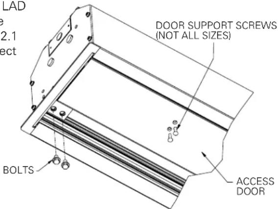
LAD e 2.1 ect DOOR SUPPORT SCREWS (NOT ALL SIZES) BOLTS ACCESS DOORFIGURE 1
CASE INSTALLATION
-
The case provides multiple attachment points for bolts, cables, or threaded rod. Page 5 shows threaded rod installed. The variable position-mounting bracket may be located anywhere along the length of the case. It is recommended to keep the brackets spaced evenly enough to distribute the weight of the screen. One mounting bracket is required for every 4' of case length.
The case has a self-trimming flange around the bottom. Ceiling tiles or drywall may be placed on top of this flange to provide a finished appearance. -
After securing the case in the ceiling check that the case is level and plumb.
-
Install electrical connections that apply to your unit. Review the wiring diagrams on page 4 for proper installation.
SCREEN AND ROLLER ASSEMBLY INSTALLATION
If your screen was shipped with the motor and roller already installed proceed to step 7.
- Remove four bolts from ends of door assembly (2 bolts on each end) (Fig. 1). This will allow the door assembly to drop open for access to case. For larger sizes, you will also need to remove the door support screws.
- Carefully unpack screen and roller assembly. Leave packing paper on the roller.
- Remove the square peg bracket from the motor end of the roller assembly.
- Remove the safety clip from the motor attachment bracket located in the motor end of the screen housing.
- Place the roller assembly into the case with the motor on the left side. The limit switches should be facing down. Line up the head of the motor with the motor attachment bracket.
- Loosen four bolts that secure pin end mounting bracket into housing. Lift pin end of roller into position and slide the bracket into the roller pin. Tighten all four bolts.
- Complete electrical hook-up by snapping motor 1/3 wire connectors into case connectors.
- Return to motor end and insert safety clip over casting bracket to secure motor end.
AUTION! DO NOT CUT TAPE ON FABRIC WITH A KNIFE OR ANY SHARP TOOL. REMOVE BY HAND.
- Carefully remove tape strips securing picture surface around roller. Slat should move freely (Fig. 2). (Only if the roller assembly is pre installed.)
- Test installation by operating the screen several times. Be prepared to stop the screen. The door assembly will not close until the wall switch is placed in the up position and when the screen motor stops at its limit switch in the up direction.
NOTE: Unit duty cycle is 1 minute on, 3 minutes off.
NOTE: Excessive continuous operation may cause the motor to overheat. If this happens the motor will shut off until it cools to a normal operating temperature.
- Close door assembly and replace four bolts at ends of door (2 bolts on each end) (Fig. 1).
text_image
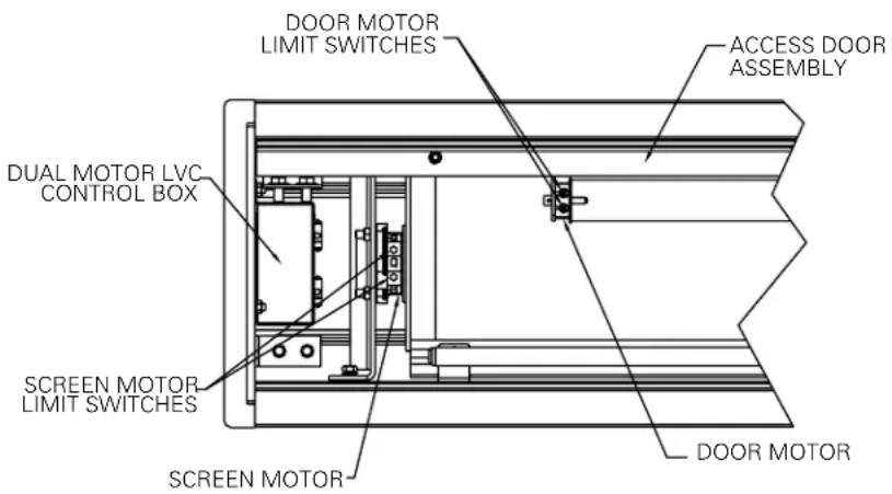
DOOR MOTOR LIMIT SWITCHES ACCESS DOOR ASSEMBLY DUAL MOTOR LVC CONTROL BOX SCREEN MOTOR LIMIT SWITCHES SCREEN MOTOR DOOR MOTORFIGURE 2
SCREEN ADJUSTMENT
RECALIBRATION
The screen controller is factory calibrated to control the screen and door sequence timing. If the line voltage varies 10% or more from the factory setting, the door will not close properly and the unit will need to be recalibrated. The steps are:
- The screen surface must be all the way up
- Press and hold the stop button for 10 seconds
The screen will then run through a whole cycle and be recalibrated upon completion. Press "up" button to close door after recalibration.
If the screen limit switch setting is changed in the up direction, the unit must be recalibrated. Surface travel is stopped automatically in the fully opened and closed positions by limit switches that are factory set at Da-Lite. Should it be necessary to adjust for more or less drop of picture, proceed in the following manner:
Surface travel is stopped automatically in the fully opened and closed positions by limit switches that are properly adjusted at Da-Lite. Should it be necessary to adjust for more or less drop of picture, proceed in the following manner:
NOTE: Use a screw driver or 5/32" Allen wrench to make adjustments.
MORE SCREEN DROP
- Place operating switch in "down" position.
- When the screen stops, turn the white "down" limit knob (Fig. 2) one-quarter turn counterclockwise. Test by raising picture surface approximately two feet, then lower again. Repeat until desired picture surface position is attained.

CAUTION: Do not adjust for more drop than what was ordered. At least 1-1/2 wraps of fabric must remain on the roller. This screen comes standard with 0" or 2" black at the top. See the specification data sheet for details.
- Recalibrate according to above instructions. Press "up" button to close door after recalibration.
LESS SCREEN DROP
- Raise picture surface approximately two feet above desired level.
- Place operating switch in "off" position.
- Turn the white "down" limit switch (Fig. 2) one-quarter turn clockwise. Test by raising picture surface approximately two feet, then lower again. Repeat until desired picture surface position is attained.
- Recalibrate according to above instructions. Press "up" button to close door after recalibration.
CONTACT DA-LITE AT 800-622-3737 IF DOOR MOTOR NEEDS ADJUSTMENT.
LARGE ADVANTAGE DELUXE® ELECTROL® INSTRUCTIONS
text_image
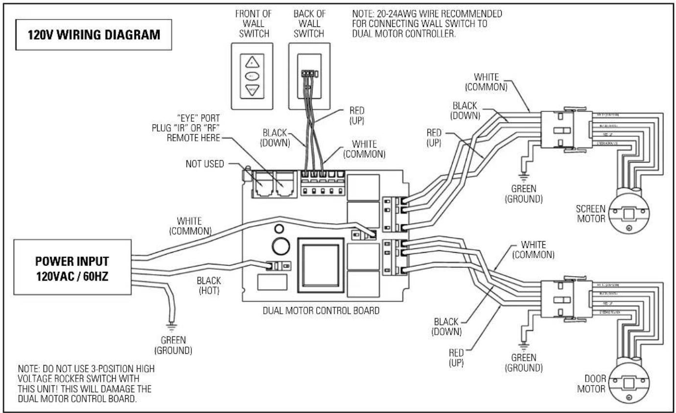
120V WIRING DIAGRAM FRONT OF WALL SWITCH BACK OF WALL SWITCH NOTE: 20-24AWG WIRE RECOMMENDED FOR CONNECTING WALL SWITCH TO DUAL MOTOR CONTROLLER. "EYE" PORT PLUG "IR" OR "RF" REMOTE HERE NOT USED WHITE (COMMON) WHITE (COMMON) BLACK (DOWN) BLACK (DOWN) RED (UP) WHITE (COMMON) GREEN (GROUND) SCREEN MOTOR POWER INPUT 120VAC / 60HZ BLACK (HOT) GREEN (GROUND) DUAL MOTOR CONTROL BOARD BLUE SHEET BLUE SHEET GREEN (GROUND) WHITE (COMMON) BLACK (DOWN) RED (UP) GREEN (GROUND) DOOR MOTOR NOTE: DO NOT USE 3-POSITION HIGH VOLTAGE ROCKER SWITCH WITH THIS UNIT! THIS WILL DAMAGE THE DUAL MOTOR CONTROL BOARD.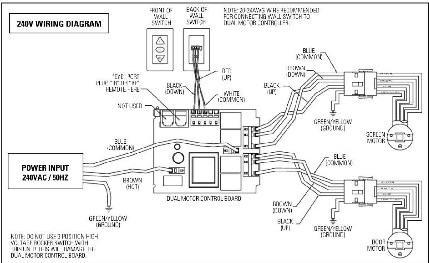
text_image
240V WIRING DIAGRAM FRONT OF WALL SWITCH BACK OF WALL SWITCH NOTE: 20-24AWG WIRE RECOMMENDED FOR CONNECTING WALL SWITCH TO DUAL MOTOR CONTROLLER. "EYE" PORT PLUG "IR" OR "RF" REMOTE HERE BLACK (DOWN) NOT USED WHITE (COMMON) BLUE (COMMON) GREEN/YELLOW (GROUND) SCREEN MOTOR POWER INPUT 240VAC / 50HZ BROWN (HOT) GREEN/YELLOW (GROUND) DUAL MOTOR CONTROL BOARD BLUE (COMMON) BROWN (DOWN) BLACK (UP) GREEN/YELLOW (GROUND) DOOR MOTOR NOTE: DO NOT USE 3-POSITION HIGH VOLTAGE ROCKER SWITCH WITH THIS UNIT! THIS WILL DAMAGE THE DUAL MOTOR CONTROL BOARD.text_image
(SUGGESTED) 1/2" THREADED ROD (NOT INCLUDED) ATTACHED TO MOUNTING BRACKET 9' /s" 11' 12" /s" 11" FINISHED CEILING SELF-TRIMMING FLANGE 13' /s"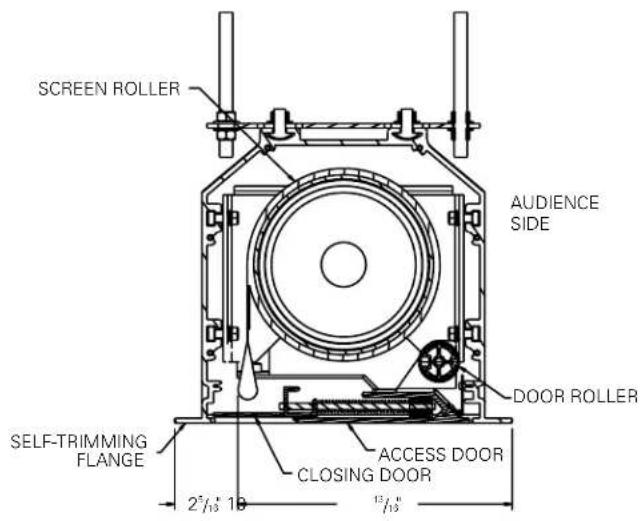
text_image
SCREEN ROLLER AUDIENCE SIDE DOOR ROLLER SELF-TRIMMING FLANGE ACCESS DOOR CLOSING DOOR 2" / 13" 10" 13 / 13"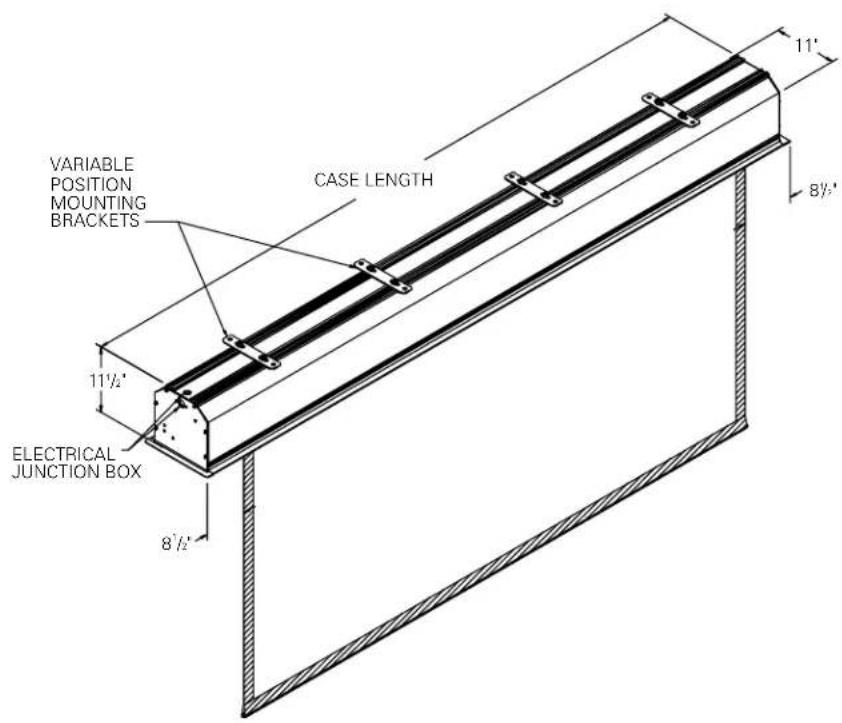
text_image
VARIABLE POSITION MOUNTING BRACKETS CASE LENGTH 11" 8½" 11½" ELECTRICAL JUNCTION BOX 8½"TROUBLESHOOTING
Visit www.da -lite.com/products/tutorials.php to find installation and troubleshooting tutorials. You will also find a link to Live Chat for interactive support and you can contact us by email at info@da-lite.com or by phone at (800) 622-3737 or (574) 267-8101 with any troubleshooting questions.
| SYMPTOM | CAUSE | SOLUTION |
| 1. Screen will not operate or will not go "down".Motor does not hum.Motor hums. | (a) Incorrect line voltage.(b) Blown facility fuse.(c) Tripped facility circuit breaker.(d) No power to operating switch or junction box.(e) Low voltage board has no power or blown transformer.Power at junction box.(f) Thermal overload tripped.(g) Broken wire in the "down" position.(h) Defective motor, limit switch or capacitor.(i) Capacitor burned out. | (a) Verify 115-125V (or 220-240V). If insufficient voltage, rewire incoming electric line.(b) Replace facility fuse.(c) Reset facility circuit breaker.(d) Check above. Tighten all loose wire connections. Recheck wiring. See installation instructions.(e) Replace low voltage board."Down" PositionCheck for power across black and white leads.(f) Let motor cool down for 15 minutes. Try again.(g) Check for continuity.(h) Replace motor assembly.NOTE: Motor is a sealed assembly.(i) Replace motor assembly. |
| 2. Screen will not move upward.Motor does not hum. | (a) Incorrect line voltage.(b) Blown facility fuse.(c) Tripped facility circuit breaker.(d) No power to operating switch or junction box.(e) Low voltage board has no power or blown transformer.(f) Open door limit switch.Power at junction box(g) Thermal overload tripped.(h) Broken wire in the "up" position.(i) Defective motor, limit switch or capacitor.(j) Capacitor burned out. | (a) Verify 115-125V (or 220-240V). If insufficient voltage, rewire incoming electric line.(b) Replace facility fuse.(c) Reset facility circuit breaker.(d) Check above. Tighten all loose wire connections. See above.(e) Replace low voltage board."Up" PositionCheck for power across red and white leads.(f) Replace switch.(g) Let motor cool down for 15 minutes. Try again.(h) Check for continuity.(i) Replace motor assembly.NOTE: Motor is a sealed assembly.(j) Replace motor assembly. |
TROUBLESHOOTING
| SYMPTOM | CAUSE | SOLUTION |
| 3. Door will not open. | (a) Spring has an obstruction not allowing door to open.(b) No power. | (a) Check installation to free door. Clear any foreign substance from spring.(b) See above. |
| 4. Door does not close. | (a) Mis-adjusted door motor limit.(b) Low voltage board has no power or a blown transformer.(c) Unit not calibrated. | (a) Adjust door motor limit. Call Da-Lite for instruction.(b) Replace low voltage board.(c) Recalibrate per instructions on page 3. |
| 5. “Down” limit switch incorrect. | (a) “Down” limit switch out of adjustment. | (a) See installation instructions. |
| 6. Noise.NOTE: Screen will operate with a low-pitched hum. | (a) Buzzing noise.(b) Gear noise. | (a) Adjust door limit switch (too far down).(b) Replace motor assembly. |
| 7. Coasting. | (a) Defective brake. | (a) Replace motor assembly. |
| 8. Roller displaced from mounting bracket. | (a) Pin end slipped out of nylon bearing. | (a) Realign pin end bracket. |
| 9. Fabric hangs crooked. | (a) Screen not installed properly.(b) Fabric is damaged. | (a) Check for level and plumb.(b) Replace fabric. |
| 10. Door closes before screen is all the way up. | (a) Screen “up” limit out of adjustment. | (a) Adjust “up” limit (call factory for instructions). |
| 11. Door opens but screen does not operate. | (a) Loose wire. | (a) Check all wiring and connections. |
LIMITED ONE YEAR WARRANTY ON DA-LITE PRESENTATION PRODUCTS
Da-Lite Screen Company, Inc. warrants its products to the original purchaser only, to be free from defects in materials and workmanship for a period of one (1) year from the date of purchase by the original purchaser provided they are properly operated according to Da-Lite's instructions and are not damaged due to improper handling or treatment after shipment from the factory.
This warranty does not apply to equipment showing evidence of misuse, abuse or accidental damage, or which has been tampered with or repaired by a person other than authorized Da-Lite personnel.
Da-Lite's sole obligation under this warranty shall be to repair or to replace (at Da-Lite's option) the defective part of the merchandise. Returns for service should be made to your Da-Lite dealer. If it is necessary for the dealer to return the screen or part to Da-Lite, transportation expenses to and from Da-Lite are payable by the purchaser and Da-Lite is not responsible for damage in shipment. To protect yourself against damage or loss in transit, insure the product and prepay all transportation expenses.
THIS WARRANTY IS IN LIEU OF ALL OTHER WARRANTIES, EXPRESS OR IMPLIED, INCLUDING WARRANTIES AS TO FITNESS FOR USE AND MERCHANTABILITY. Any implied warranties of fitness for use, or merchantability, that may be mandated by statute or rule of law are limited to the one (1) year warranty period. This warranty gives you specific legal rights, and you may also have other rights, which vary from state-to-state. NO LIABILITY IS ASSUMED FOR EXPENSES OR DAMAGES RESULTING FROM INTERRUPTION IN OPERATION OF EQUIPMENT, OR FOR INCIDENTAL, DIRECT, OR CONSEQUENTIAL DAMAGES OF ANY NATURE.
In the event that there is a defect in materials or workmanship of a Da-Lite product, you may contact our Sales Partners at PO Box 137, Warsaw, IN 46581-0137, (574) 267-8101, (800) 622-3737.
IMPORTANT: THIS WARRANTY SHALL NOT BE VALID AND DA-LITE SHALL NOT BE BOUND BY THIS WARRANTY IF THE PRODUCT IS NOT OPERATED IN ACCORDANCE WITH DA-LITE'S WRITTEN INSTRUCTIONS.
Keep your sales receipt to prove the date of purchase and your original ownership.