USER MANUAL X9 500 PIAGGIO
"All rights reserved. Reproduction, in whole or in part, forbidden."
Data subject to change without notice.
No responsibility is assumed for the use of non-genuine components and accessories other than those tested
and approved by the Manufacturer.
SERVICE STATION
MANUAL
X9 500 cc
This manual has been designed by Piaggio for use in authorized dealers' and subdealers' workshops.
It is assumed that those who use this publication for maintaining and repairing Piaggio vehicles are familiar with the principles of mechanics and with vehicle repairing procedures and techniques. Any significant changes to the characteristics of the vehicles or to specific repairing procedures will be covered in updates of this manual.
Since satisfactory results cannot be obtained without the necessary equipment and tooling, we recommend referring to the pages of this manual concerning the specific equipment required and to the catalogue of specific tools.
Pieces of particularly important information are identified as follows:
Note: Provides important information intended to simplify and clarify a procedure.
Warning - Denotes specific procedures to be used to avoid damaging the vehicle.
Caution - Identifies specific procedures to be followed to avoid injury to repairing personnel.
NOTE - For any intervention to the engine, refer to the "Service Station Manual" for 500 cc Engines.
TABLE OF CONTENTS
VEHICLE SPECIFICATIONS AND OVERHAUL DATA
1
SPECIFIC TOOLING
2
MAINTENANCE AND TROUBLESHOOTING
3
ELECTRICAL EQUIPMENT
4
ENGINE
5
FRONT AND REAR SUSPENSIONS
6
BRAKING SYSTEM
7
BODYWORK
8
PREDELIVERY OPERATIONS
9
TABLE OF WORKING TIMES
10
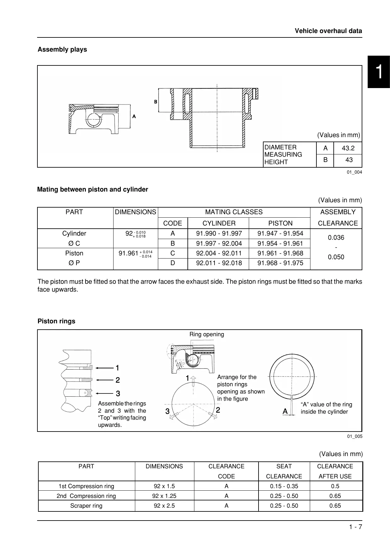
Assembly plays
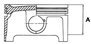
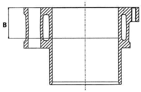
(Values in mm)
| DIAMETER | A | 43.2 |
| MEASURING |
| HEIGHT | B | 43 |
01_004
Mating between piston and cylinder
(Values in mm)
| PART | DIMENSIONS | MATING CLASSES | ASSEMBLY CLEARANCE |
| CODE | CYLINDER | PISTON |
| Cylinder
Ø C | 92-0.010
+0.018 | A | 91.990 - 91.997 | 91.947 - 91.954 | 0.036
-0.050 |
| B | 91.997 - 92.004 | 91.954 - 91.961 |
| Piston
Ø P | 91.961 +0.014
-0.014 | C | 92.004 - 92.011 | 91.961 - 91.968 |
| D | 92.011 - 92.018 | 91.968 - 91.975 |
01_005
The piston must be fitted so that the arrow faces the exhaust side. The piston rings must be fitted so that the marks face upwards.
Piston rings
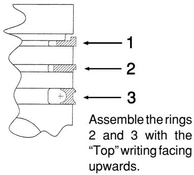
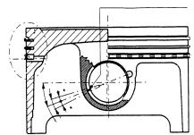
Ring opening
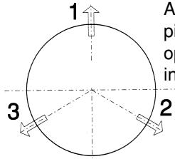
Arrange for the piston rings opening as shown in the figure
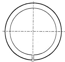
A
"A" value of the ring inside the cylinder
(Values in mm)
| PART | DIMENSIONS | CLEARANCE
CODE | SEAT
CLEARANCE | CLEARANCE
AFTER USE |
| 1st Compression ring | 92 x 1.5 | A | 0.15 - 0.35 | 0.5 |
| 2nd Compression ring | 92 x 1.25 | A | 0.25 - 0.50 | 0.65 |
| Scraper ring | 92 x 2.5 | A | 0.25 - 0.50 | 0.65 |
SHIMMING METHOD FOR LIMITING THE COMPRESSION RATIO:CR=10.5:1
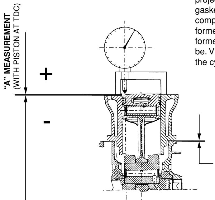
N.B.: The “A” measurement is referred to the piston projection or recess value; it indicates the type of gasket to be fitted on the cylinder to restore the compression ratio. Therefore the more the surface formed by the piston crown sticks out of the surface formed by the cylinder top, the thicker the gasket will be. Vice versa, the more the piston crown is hollow to the cylinder top, the less thick the gasket will be.
FIT THE GASKETS SHOWN IN THE TABLE ACCORDING TO THE “A”MEASUREMENT
NOTE: THE “A” MEASUREMENT MUST BE TAKEN WITH NO GASKET FITTED BETWEEN CRANKCASE AND CYLINDER
01_006
| “A” MEASUREMENT | THICKNESS OF BASE GASKET |
| -0.185 -- 0.10 | 0.4 ± 0.05 |
| -0.10 - + 0.10 | 0.6 ± 0.05 |
| +0.10 - + 0.185 | 0.8 ± 0.05 |
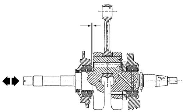
Crankshaft/crankcase axial clearance 0.1 - 0.5 mm (cold engine)
01_010
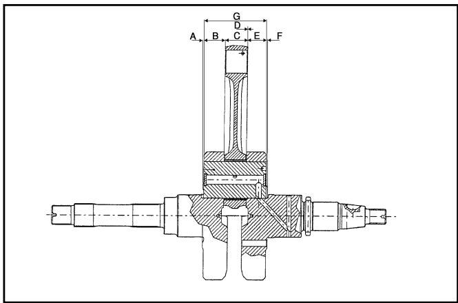
Crankshaft/connecting rod axial clearance
01_007
| PART | DIMENSIONS | CLEARANCE |
| Web, transmission side | A =0.8 ± 0.025 | D = 0.20 - 0.40 |
| Shaft section, transmission side | B =19.6 + 0.05 |
| Connecting rod | C =22 - 0.10 |
| - 0.15 |
| Shaft section, flywheel side | E =19.6 + 0.05 |
| Web, flywheel side | F =13 ± 0.025 |
| Crankshaft assembly | G =63.5 + 0.1 - 0.05 |
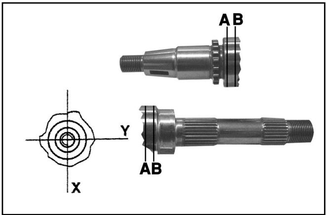
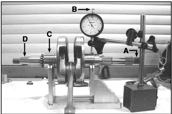
Crankshaft alignment and diameters
- Measure the housings on both axes x and y .
| Standard diameter |
| Class 1 | 40.010 - 40.016 |
| Class 2 | 40.016 - 40.022 |
01_008
Max. allowable runout:
A = 0.15 ~mm
B = 0.01 mm
C = 0.010 ~mm
D = 0.10 mm
01_009
TABLE OF CONTENTS
SPECIFIC TOOLING
2

Specific tools for Piaggio X9 500 cc 4-stroke 4-valve
| RECOMMENDED TOOLS |
| TOOL NAME | PART NO. |
| Circlip pliers | 002465Y |
| Steering thrust ring removing drift | 020004Y |
| Crankshaft aligning tool | 020074Y |
| Support for “METABO HG 1500/2” air heater | 020150Y |
| “METABO HG 1500/2” air heater | 020151Y |
| Mityvac-type vacuum pump | 020329Y |
| Stroboscopic gun for two- and four-stroke engines | 020330Y |
| Digital multimeter | 020331Y |
| Single battery charger | 020333Y |
| Multiple battery charger | 020334Y |
| Magnetic stand and dial gauge | 020335Y |
| Engine support connection | 020482Y |
| Engine mount base | 020527Y |
| Engine mount revolving base | 020604Y11 |
New tools
| NECESSARY TOOLS |
| TOOL NAME | PART NO. |
| STEERING SEAT FITTING TOOL, to be fitted with parts 9 - Lower bearing adaptor, 10 - Upper bearing adaptor | 001330Y |
| Bell Ø 80 mm | 001467Y002 |
| 20 mm pliers | 001467Y006 |
| Bell Ø 63 mm | 001467Y007 |
| 18 mm pliers | 001467Y008 |
| Bell Ø 45 mm | 001467Y017 |
| Bell Ø 60 mm | 001467Y031 |
| 15 mm pliers | 001467Y034 |
| Hub bearing extraction bell | 001467Y035 |
| Steering tube ring spanner | 020055Y |
| Oil pressure gauge | 020193Y |
| Valve seal rings assembly tool | 020306Y |
| 37x40 mm adaptor | 020358Y |
| 42x47 mm adaptor | 020359Y |
| 52x55 mm adaptor | 020360Y |
| 20 mm guide (Driven pulley bearings) | 020363Y |
| 25 mm guide (Driven pulley bearings) | 020364Y |
| Ø 28x30 mm adaptor | 020375Y |
| Adapter sleeve | 020376Y |
| Bushing (valve removing tool) | 020382Y012 |
| 15 mm guide | 020412Y |
| Valve oil seal extractor | 020431Y |
| Oil pressure gauge unio | 020434Y |
| 17 mm guide (countershaft bearings) | 020439Y |
| Driven half pulley spring compressor | 020444Y |
| 46-55 mm spanner | 020444Y009 |
| Ø 24 mm adaptor | 020456Y |
| Steering tube lower bearing extractor | 020458Y |
| Drift for fitting bearing on steering tube | 020459Y |
| Injection tester kit | 020460Y |
| Flywheel extractor | 020467Y |
| Piston fitting band | 020468Y |
| Injection tester reprogramming kit | 020469Y |
| Piston pin retainer fitting tool | 020470Y |
| Countershaft timing peg | 020471Y |
| Flywheel retaining tool | 020472Y |
| Clutch bell housing retaining tool | 020473Y |
| Drive pulley stop spanner | 020474Y |
| Piston position comparator support | 020475Y |
| Pillar kit | 020476Y |
| Ø 37 mm adaptor | 020477Y |
| Driven pulley needle roller drift | 020478Y |
| Countershaft stop spanner | 020479Y |
| Fuel pressure measuring kit | 020480Y |
| Control unit interface wiring harness | 020481Y |
| 30 mm guide | 020483Y |
| Piston stop fork | 020512Y |
| Compass wrench (valve lifter bell stop) | 020565Y |
| Exhaust gas analyser | 494929 |
Spark plug
Check and replacement
Warning - Remove the spark plug when the engine is cold. Replace the spark plug every 12,000 km. The use of unsuitable ignition control units and spark plugs other than those specified can seriously damage the engine.
Recommended spark plug: CHAMPION RG 6 YC NGK CR 7 EKB
- Put the vehicle on the central stand.
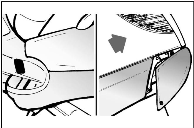
- Open the door on the left side of the vehicle by levering in the recess in the lower part of the door after removing the screw.
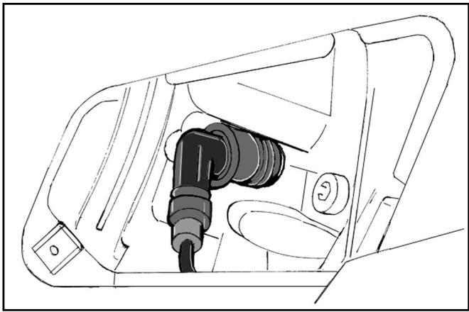
- Disconnect the spark plug HV cable cap.
- Unscrew the spark plug with the spanner provided.
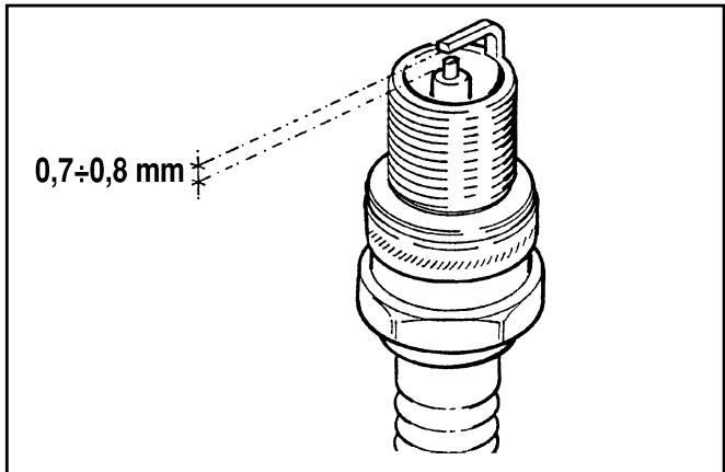
- Check the spark plug to see if the insulator is cracked, the electrodes are worn out or excessively sooty. Also check the condition of the seal washer and measure the spark gap with a suitable thickness gauge.
Spark gap: 0,7 - 0,8 mm
- If necessary adjust the spark gap by carefully bending the side electrode.
If the spark plug has any of the defects mentioned above, replace it with a plug of the recommended type.
- Insert the plug into the hole with the proper inclination, screw it in fully by hand and then tighten it with the specially designed spanner.
Tightening torque: 10N· m (1 Kg·m)
- Push the spark plug cap all the way down onto the spark plug and then proceed to the reassembly.
03_001
03_002
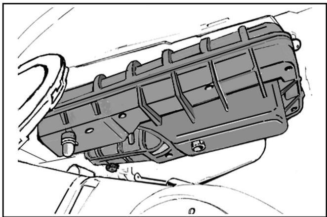
Air filter
- Remove the left-hand lower side panel as described in Chapter 8-Bodywork.
- Remove the cleaner cap after loosening the eight fixing screws, including one screw of the knob type.
- Pull out the filter element.
- Replace the air filter with a new one.
Note: Check and if necessary blow the air filter every 6,000km . Direct the air jet from the inside to the outside of the filter (i.e. in the opposite direction to the air flow during normal engine operation).
03_003
Warning - If the vehicle is mostly used on dusty roads, the air filter needs to be cleaned and replaced at shorter intervals than indicated in the Maintenance Schedule.
Warning - Do not run the engine if the air filter is not in place as this would result in excessive wear of the cylinder and piston as well as in damage to the throttle body.
03_004
Engine oil level
In four-stroke engines oil is used to lubricate the valve gear components, the crankshaft bearings and the power plant. A lack of engine oil can cause serious damage to the engine.
In all four-stroke engines, oil deterioration and consumption are, to some extent, normal, especially during running-in. Consumption partly depends on the riding style (for example, constantly riding at full throttle increases oil consumption).
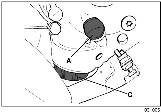
Checking the oil level
Perform this operation when the engine cold, as described below:
1) Put the vehicle on its central stand on a flat surface.
2) Unscrew dipstick «A», dry it with a clean cloth and refit by screwing it completely.
3) Remove the dipstick again and check that the oil level is between the MAX and MIN marks on the dipstick; top up if necessary.
The MAX level mark indicates an amount of about 1700 cc of engine oil.
The level will be lower if checked after using the vehicle (i.e. when the engine is hot). To obtain a correct indication of the oil level, wait for at least 10 minutes after switching off the engine.
Topping up
If the oil level is too low, top up by adding fresh oil without exceeding the MAX level.
Approximately 400 cc of oil are needed to restore the level between the MIN and MAX marks.
Oil pressure warning light
A warning light on the instrument panel comes on when the ignition key is turned to the "ON" position. The light must go out after the engine has started.
Should the warning light come on while braking, idling or cornering, check the oil level and the lubrication system as soon as possible.
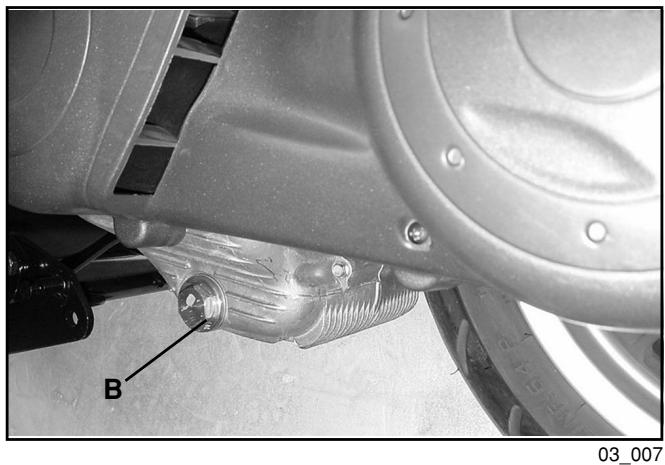
Renewing the oil and the filter
The oil and the filter must be renewed every 6,000~km . Drain all the oil from the engine by removing gauze strainer drain plug «B» on the transmission side. To facilitate the outflow, also remove cap/dipstick «A». Once the oil has drained completely through the drain hole, unscrew oil filter cartridge «C» and remove it as described below.
Since a certain amount of oil remains in the circuit, the replenishment must be made by adding approximately 1,500 cc of fresh oil through cap «A». Subsequently start the engine, let it idle for a few minutes and then switch it off. After about 5 minutes, check the level and if necessary top up without exceeding the MAX level. The filter cartridge must be replaced every time the oil is changed. For top-ups and renewals use fresh oil of the Selenia HI Scooter 4 Tech type.
Note: Renew the oil when the engine is hot.

Replacing the filter
Warning - Do not dispose of the oil in the environment. Carry out the disposal of the oil, the gasket and the filter in accordance with the law.
Caution - To avoid burns, take care not to touch hot engine parts.
- Remove the silencer.
- Remove filler plug «A».
- Remove and clean the drain plug gauze strainer with compressed air.
- Using a strap wrench for filters, remove cartridge filter «C».
- Ensure that the O-rings on the prefilter and the drain plug are in good condition.
- Lubricate the O-rings and then refit the gauze strainer and the oil drain plug. Tighten the drain plug with the prescribed torque.
- Fit a new cartridge filter after lubricating the O-ring. Turn in until the gasket makes contact and then tighten it with the prescribed torque.
- Reinstall the silencer.
- Add engine oil as previously described.
Tightening torque:
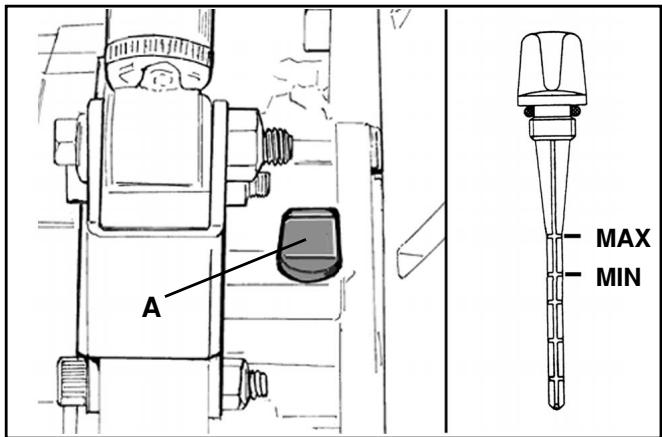
Checking the hub oil level
- Put the vehicle on the central stand on level ground.
- Unscrew oil dipstick «A», wipe it with a clean cloth, reinsert it and then screw it in fully.
- Pull out the dipstick again and check that the oil level is between the MIN and MAX marks (see figure); if the level is below the MIN mark, top up with oil.
- Reinsert the dipstick and screw it tight.
Renewing the hub oil
- Remove oil filler plug «A».
- Unscrew oil drain plug «B» and drain all the oil.
- Retighten the oil drain plug and then fill the hub with fresh oil.
Recommended oil: TUTELA ZC 90
Hub oil capacity: 250 cc
03_008
03_009
Engine cooling
Adding coolant and bleeding air from the system
The level of the fluid must be checked every 6,000 km when the engine is cold.
Follow these steps:
- Put the vehicle on the central stand on level ground.
- Remove the expansion tank cap and top up if the coolant is below or near the MIN level in the expansion tank. The level of the fluid should always be between the MIN and MAX marks.
- To have an indication of the coolant level, refer to the groove in the plastic strip that can be seen through the coolant filler hole. The upper and lower parts of the groove correspond to the MAX and MIN levels respectively.
- The coolant consists of a 50 percent mixture of demineralized water and antifreeze solution with a base of ethylene glycol and corrosion inhibitors.
Total coolant capacity: 1,8 lt
- To check the presence of air in the circuit follow the procedure described in Chapter 11-Cooling, in the manual of Engine 500 cc.
- Switch off the engine and allow it to cool down. After a few minutes, remove the expansion tank cap and check the level of the fluid.
- If necessary, top up by pouring fresh coolant into the expansion tank up to the correct level.
Warning - To prevent the coolant from leaking out of the expansion tank during use, be sure to never exceed the MAX level when refilling.

03_010
03_011
Water pump
If the water pump becomes noisy or liquid leaks through the pump drain hole, check the water pump as described in Chapter 5-Flywheel cover of the manuale Engine 500 cc. Perform the following preliminary operations:
- Put the vehicle on the central stand on level ground.
- Remove the lower right-hand side panel and the right-hand footboard as described in Chapter 8-Bodywork.
- Remove the silencer to gain access to the flywheel cover as described in Chapter 5-Engine;
- Remove the sleeves from the water pump cover and the filler cap from the expansion tank and empty the cooling circuit.
Warning - Perform the operation when the engine is cold.
- Remove the water pump cover shown in the figure after loosening the six fixing screws.
-
Cooling circuit capacity: 1,8 lt.
-
As described in the manual Engine 500cc, partially drain the system and overhaul the pump.
- After solving the problem and refitting all components, fill and bleed the cooling circuit again.
N.B.: Change the coolant as described in Chapter 11-Cooling of the Manual Engine 500 cc
03_013
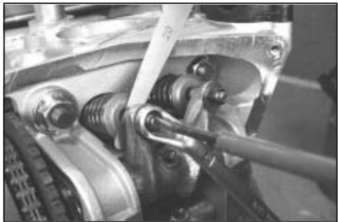
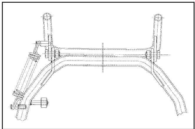
Adjusting the play of the valves - Checking the valve gear timing
To adjust the play of the valves and to check the valve gear timing as described in Chapter 7-Thermal Unit and Timing system of the Engine manual, follow these preliminary steps:
- Put the vehicle on the central stand;
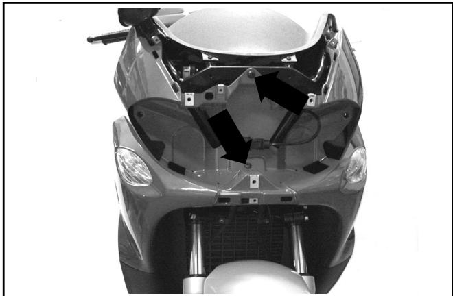
- Remove the relevant body sections to gain access to the pivot fixing the engine to the swingarm (refer to Chapter 8-Bodywork);
- Support the bottom of the engine, e.g. with a jack;
- Remove the engine from the frame as described in Chapter 5-Engine;
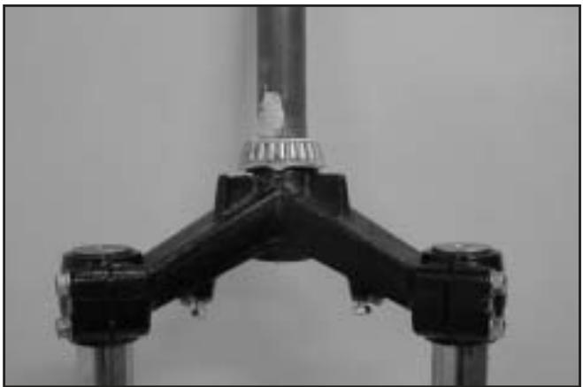
- Shift the engine backwards to make room for the removal of the cylinder head cover (until the swingarm cross member touches the starter motor).
- After adjusting the play of the valves, refit the components by following the reverse procedure to the removal.
Warning - Do not lower the engine too much to prevent it from touching the stop push button of the electrohydraulic stand.
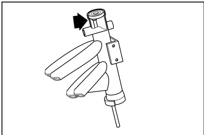
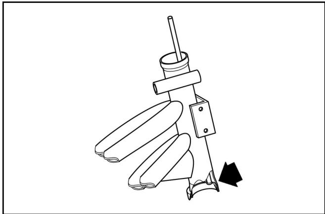
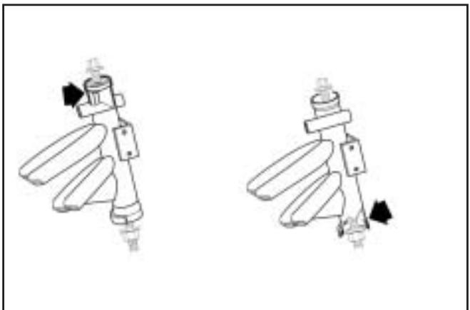
Note: The checking areas are shown in the two figures at the right.
Play of valves:
Intake 0.15mm cold engine
Exhaust 0.15mm cold engine
03_012
03_012_4
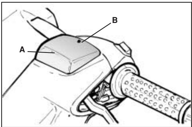
Checking the level
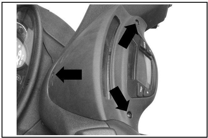
To gain access to the front and rear brake fluid reservoirs, remove the covers on the handlebar cover.
Follow these steps:
- Put the vehicle on the central stand and turn the handlebar to the central position.
- Remove cap «A» after loosening fixing screw «B».
- Check the level of the fluid through the sight.
A certain decrease in the level of the fluid occurs as a result of pad wear.
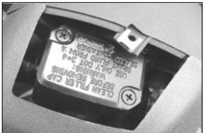
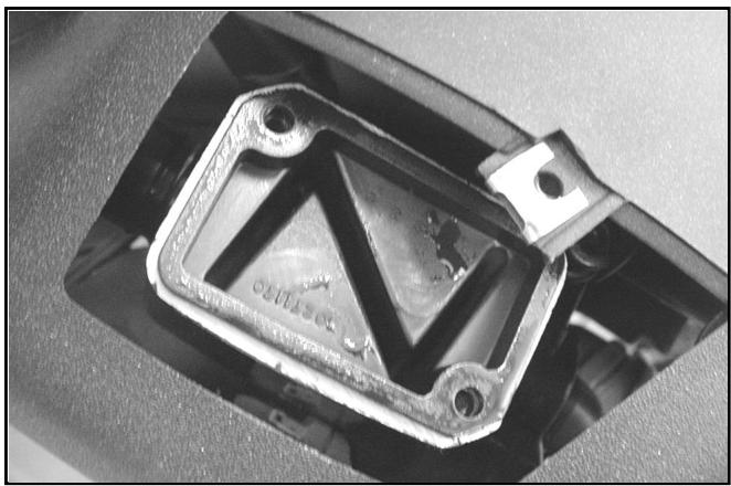
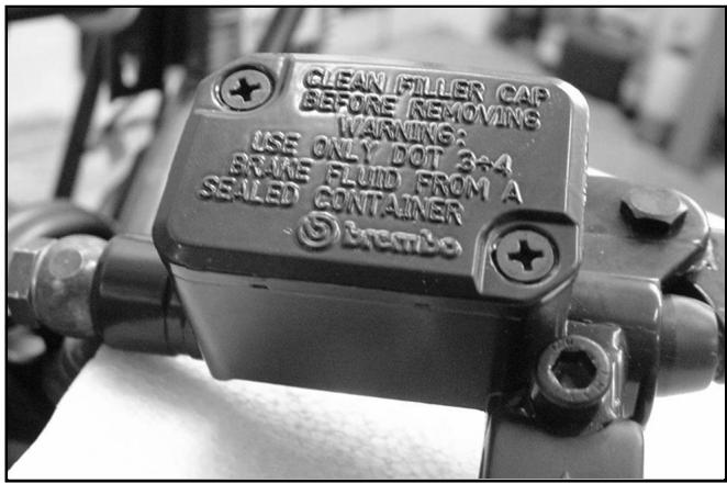
Restoring the brake fluid level
Warning -Only use brake fluid classified as DOT 4.
Brake fluid type: TUTELA TOP 4
Use the following procedure:
Remove the «A», covers and the tank cap by unscrewing the two screws, remove the gasket and restore the brake fluid level with liquid of the recommended type, without exceeding the max. level.
03_012_1
03_012_2
Warning - Keep the brake fluid away from the skin, the eyes and clothing. In case of contact, rinse generously with water.
Warning - The brake fluid is highly corrosive. Take care not to spill it on the paintwork.
Warning - The brake fluid is hygroscopic, i.e. it absorbs humidity from the air. If the humidity contained in the fluid exceeds a given concentration, the braking action becomes insufficient.
Never draw the fluid from open or partly empty containers.
Under normal climatic conditions the fluid should be renewed every 20,000 km, or in any case every two years.
N.B.: Change the brake fluid and bleed the system as described in Chapter 7-Braking system.
03_012_3
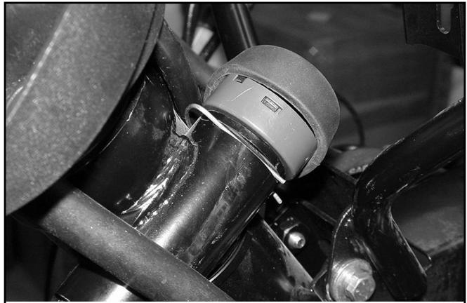
Steering lock
Disassembly with lock turned to "OFF"
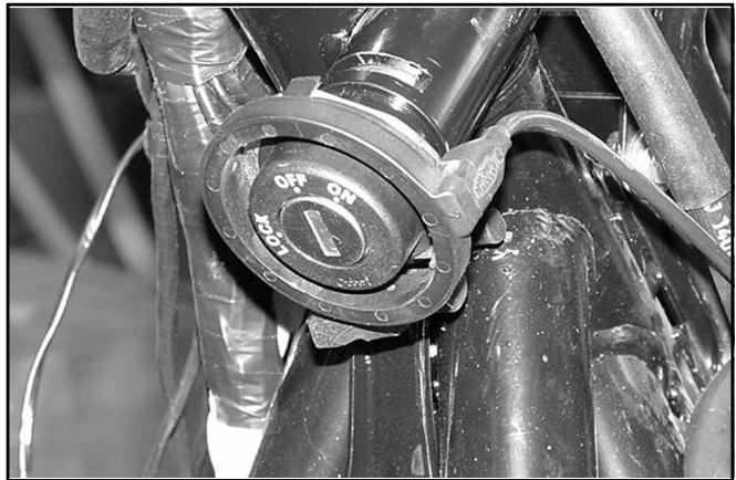
03_014
03_015
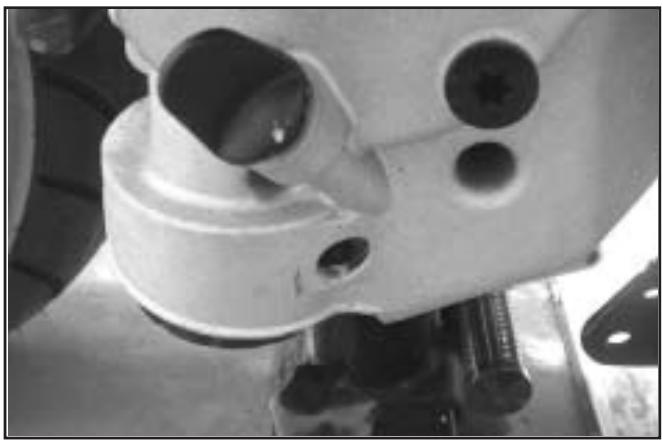
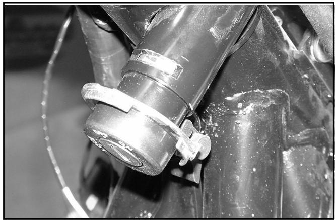
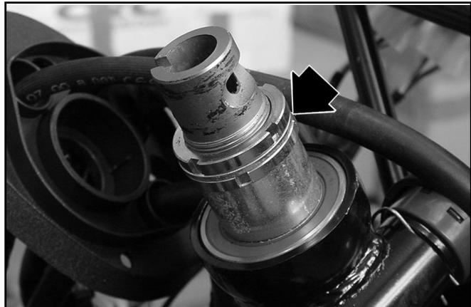
- Push the bolt lightly and extract the retainer from the milled part shown in the figure.
- Extract the bolt assembly from the lock body.
- To refit, follow the reverse procedure.
03 016
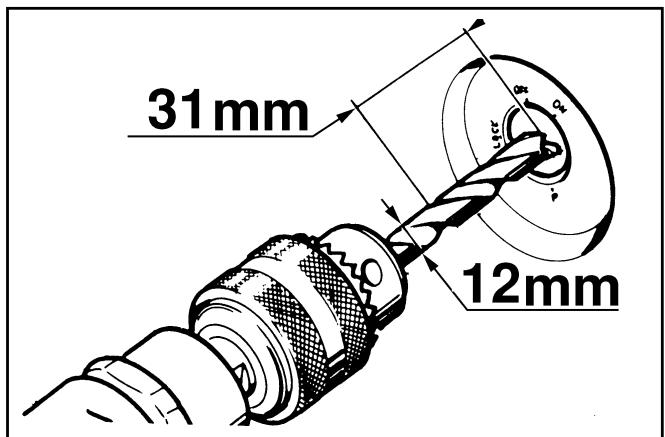
Removal with lock in LOCK position
The bolt retaining spring is not accessible in the LOCK position. It is then necessary to drill the bolt as show in the figure to eject it.
Note: To refit the bolt from this position, first disengage the steering lock by putting the lock body (inner and outer part) in the OFF position.
Proceed as described in the previous paragraph.
03_017
Adjusting the headlight
- Place the unloaded vehicle on a level surface, 10 metres from a half-lit white screen, with the tyres inflated to the prescribed pressure. Ensure that the axis of the vehicle is perpendicular to the screen.
- Draw a horizontal line on the screen 70-73 cm above the ground.
- Switch on the headlight, turn on the low beam and check that the horizontal line that divides the dark area from the lighted area is not above the line previously drawn on the screen. To shift the headlight, use the specially designed screw in the front shield (see figure).

03_018
TABLE OF CONTENTS
ELECTRICAL EQUIPMENT
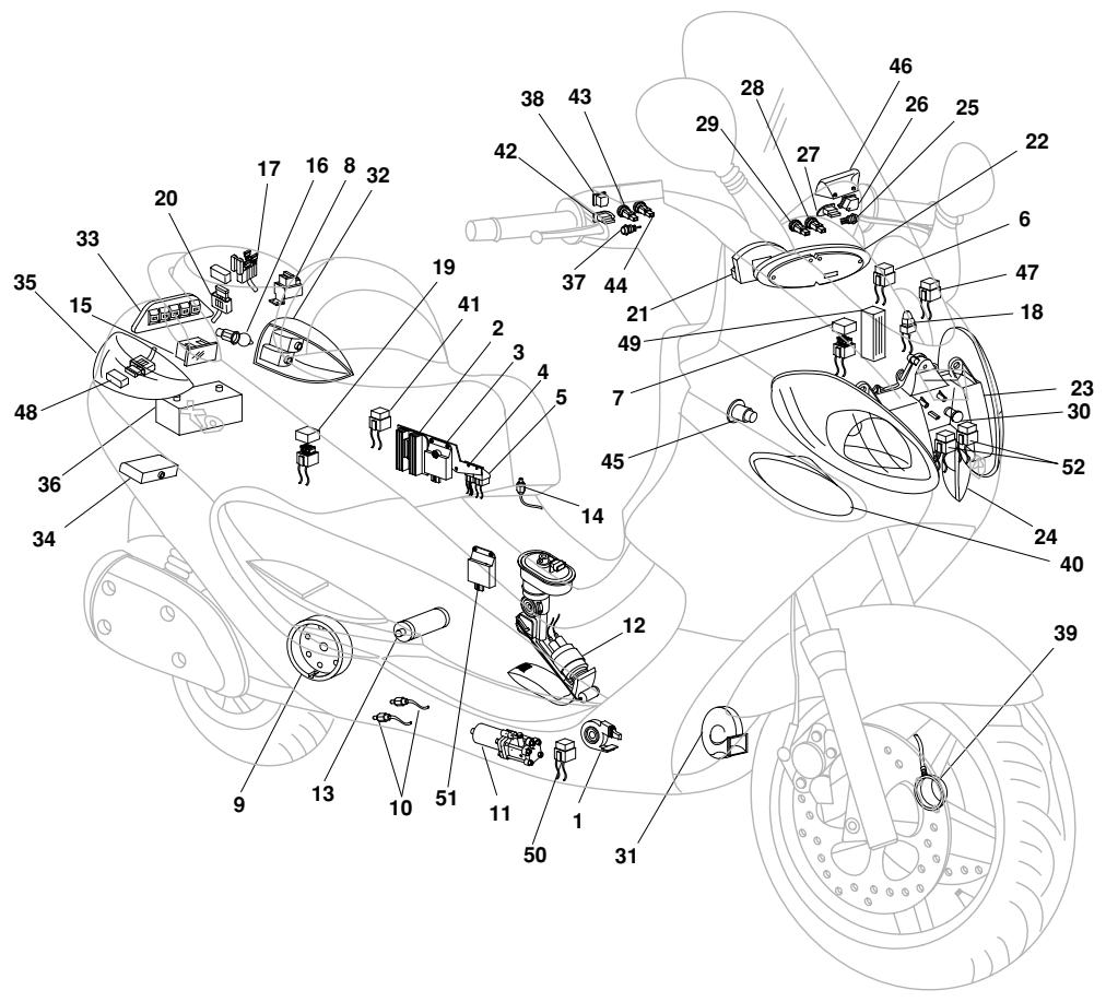
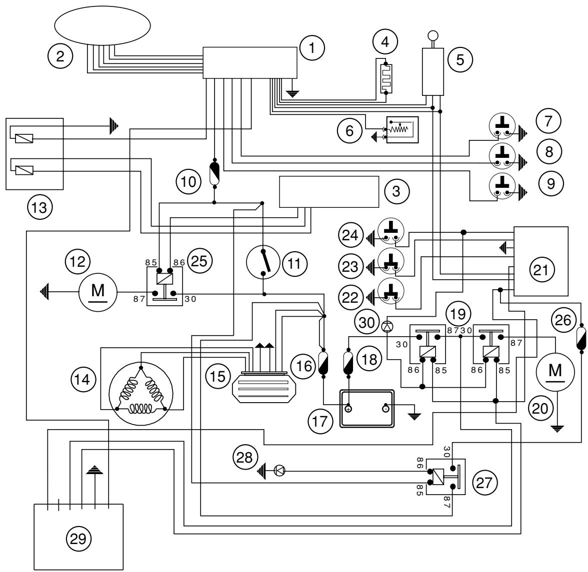
| 1 | SIDESTAND SWITCH | 27 | TURN INDICATOR SWITCH |
| 2 | VOLTAGE REGULATOR | 28 | HORN BUTTON |
| 3 | STAND CONTROL UNIT | 29 | HAZARD WARNING LIGHT BUTTON |
| 4 | ELECTRONIC CONTROL UNIT RELAY SWITCH | 30 | RESET BUTTON |
| 5 | ENGINE STOP RELAY SWITCH | 31 | TRUMPET HORN |
| 6 | SERVICES ELECTROMAGNETIC SWITCH | 32 | LH REAR LIGHT WITH 5W PARKING LIGHT BULB AND 10W TURN INDICATOR BULB |
| 7 | FUSE BOX (3 X 7.5A, 1 X 15A) |
| 8 | NO. 2 SOLENOID STARTERS | 33 | REAR BRAKE LIGHT, 5 X 2.3W BULB |
| 9 | 375W FLYWHEEL MAGNETO |
| 10 | 2 X STAND BUTTON | 34 | NUMBER-PLATE LIGHT 12V-5W |
| 11 | STAND PUMP MOTOR | 35 | RH REAR LIGHT WITH 5W PARKING LIGHT BULB AND 10W TURN INDICATOR BULB |
| 12 | PUMP ASSEMBLY WITH LEVEL INDICATOR |
| 13 | STARTER MOTOR | 36 | 12V-14Ah BATTERY |
| 14 | HELMET COMPARTMENT LAMP BUTTON | 37 | FRONT BRAKE LIGHT BUTTON |
| 15 | HELMET COMPARTMENT LAMP | 38 | ENGINE STOP SWITCH |
| 16 | 12V SOCKET | 39 | WHEEL REVOLUTION SENSOR |
| 17 | 2 X REAR FUSE BOX FOR CONTROL UNIT (1 X 3A, 1 X 5A, 1 X 10A, 1 X 3A) | 40 | RH FRONT TURN INDICATOR, 10W BULB |
| 41 | MAIN RELAY SWITCH |
| 18 | DIODE BOX (2 X 6 A AND 2 A DIODE) | 42 | LIGHTS SELECTOR SWITCH |
| 19 | FUSE BOX (2 X 7.5A, 1 X 15A AND 5A) | 43 | START BUTTON |
| 20 | FUSE BOX WITH STRIP FOR STAND PUMP ELECTROMAGNETIC SWITCH (NO. 1 OF 70A) | 44 | STAND BUTTON |
| 45 | IGNITION SWITCH |
| 21 | DIGITAL INSTRUMENT SET (11 WARNING LIGHTS AND LEDs) | 46 | RADIO DISPLAY |
| 22 | ANALOG INSTRUMENT SET (5 LAMPS) | 47 | ELECTRIC FAN RELAY SWITCH |
| 23 | HEADLIGHT, 2 X PARKING LIGHT BULB, HIGH/LOW BEAM 55/55W BULB | 48 | 30A FUSE WITH SOLENOID STARTER |
| 49 | RADIO CONTROL UNIT/INTERCOM/SPEAKERPHONE |
| 24 | LH FRONT TURN INDICATOR WITH 10W BULB | 50 | No. 2 PUMP ELECTROMAGNETIC SWITCHES |
| 25 | REAR BRAKE LIGHT BUTTON | 51 | RELAY SIGNALER GLUED |
| 26 | LIGHTS SWITCH WITH HEADLIGHT FLASH | 52 | No. 2 HEADLIGHT ELECTROMAGNETIC SWITCHES |
Electrical equipment devices
- Digital instrument panel (11 LED indicators).
- Analog instrument panel (5 bulbs).
- Headlight (2 parking light bulbs, 55/55W low/high beam bulbs).
- LH front turn indicators (10W bulb).
- Rear brake light button.
- Lights selector switch with headlight flash.
- Turn indicator switch.
- Horn button.
- Hazard warning light button.
- Reset button.
- Trumpet horn.
- Sidestand switch.
- Voltage regulator.
- Stand control unit.
- Engine stop relay switch.
- Electronic control unit relay switch.
- Stand pump relay switches.
- LH rear light (5W parking light bulb, 10W turn indicator bulb).
- Rear brake light (5 x 2.3W bulbs).
- Number-plate light with bulb.
- RH rear light (5W parking light bulb, 10W turn indicator bulb).
- 12V-14Ah battery.
- Fuse box (3 x 7.5A fuse, 1 x 15A fuse).
- Starting relay switch.
- Flywheel magneto (375W).
- Engine oil pressure sensor.
- Coolant temperature sensor.
- Engine rpm sensor.
- Air temperature sensor.
- Idle speed adjusting motor.
- Throttle potentiometer.
- Petrol injector.
33.2 stand switches.
- Stand pump motor.
- Injection electronic control unit.
36.Decoder.
- Front brake light button.
- Engine stop switch.
39.Wheel revolution sensor.
- RH front turn indicator (10W bulb).
ELECTRICAL CABLES COLOUR: B=White - BI=Blue - G=Yellow - Mr=Brown - N=Black - BV=White-Green - GN=Yellow-Black - Gr=Grey - Rs=Pink - R=Red - Vi=Violet - V=Green - VN=Green-Black - BN=White-Black - BBI=White-Blue - GV=Yellow-Green - Ar=Orange - Az=Azure - GrBI=Grey-Blue - GrN=Grey-Black.
Warning - When working on the electrical equipment, take special care to ensure that the leads that link up to the electronic control device are properly connected by observing the polarity and colour coding of the connectors.
- Relay switch.
- Lights switch.
- Start button.
- Stand button.
- Immobilizer aerial.
- Ignition switch.
- Electric fan.
- Electric fan relay switch.
- Main relay switch.
- HV coil.
- Fuel gauge with pump.
- Starter motor.
- Helmet compartment lamp button.
- Helmet compartment lamp.
55.12V socket.
- 2 rear fuse boxes for control unit (1 x 3A fuse, 1 x 5A fuse, 1 x 10A fuse, 1 x 3A fuse).
- Radio display.
- Relay switch.
- Outside temperature sensor.
- Diode box (2 x 6A/2A diodes).
- Fuse box (2 x 7.5A fuse, 1 x 15A fuse, 1 x 5A fuse).
- Fuse box with base for stand pump (1 x 70A fuse).
- Intercom/radio control unit.
- Intercom connectors.
- Relay signaler glued.
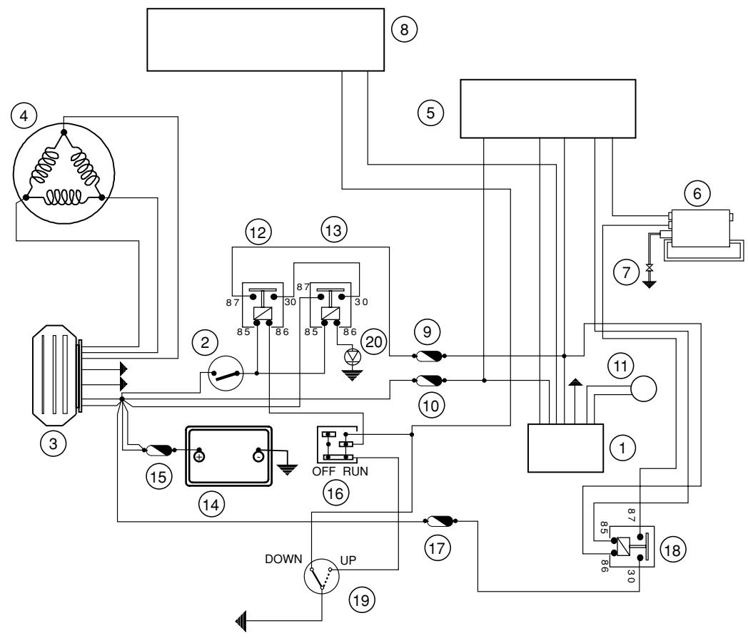
Ignition section
04_002
| 1 | IMMOBILIZER DECODER | 11 | IMMOBILIZER AERIAL |
| 2 | IGNITION SWITCH CONTACTS | 12 | ENGINE STOP RELAY SWITCH |
| 3 | VOLTAGE REGULATOR | 13 | MAIN RELAY SWITCH |
| 4 | FLYWHEEL MAGNETO | 14 | 12V-14Ah BATTERY |
| 5 | INJECTION ELECTRONIC POWER UNIT | 15 | 30A FUSE |
| 6 | HV COIL | 16 | ENGINE STOP SWITCH |
| 7 | SPARK PLUG | 17 | 10A FUSE |
| 8 | DIGITAL INSTRUMENT SET | 18 | ELECTRONIC POWER UNIT ELECTROMAGNETIC SWITCH |
| 9 | 5A FUSE | 19 | SIDE STAND SWITCH |
| 10 | 3A FUSE | 20 | 2A DIODE |
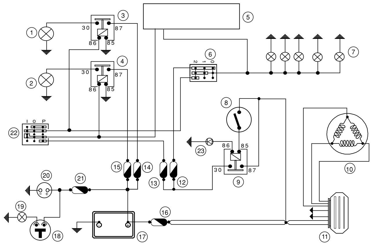
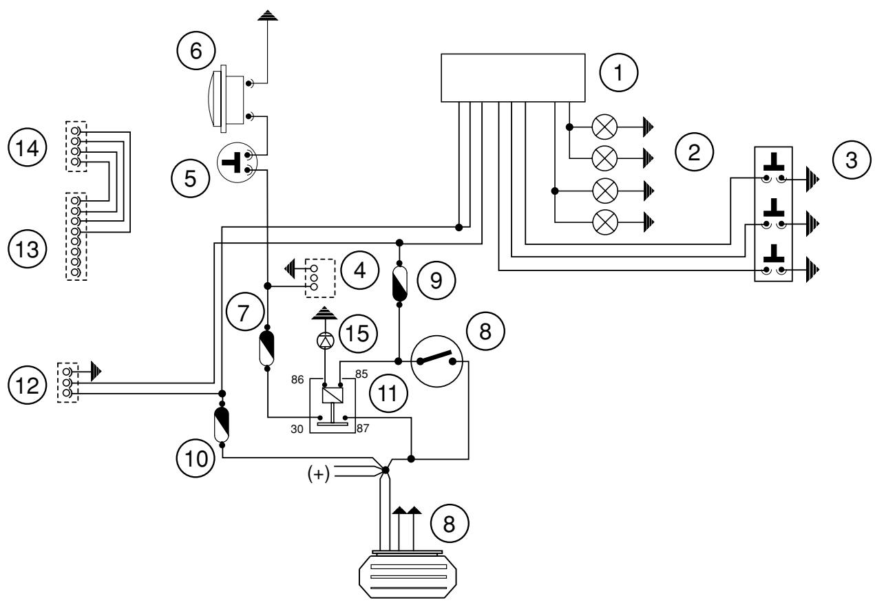
Lights section
04_003
| 1 | 12V-55W LOW BEAM BULB | 12 | 7.5 A FUSE |
| 2 | 12V-55W HIGH BEAM BULB | 13 | 15 A FUSE |
| 3 | LOW BEAM RELAY SWITCH | 14 | 7.5 A FUSE |
| 4 | HIGH BEAM RELAY SWITCH | 15 | 7.5 A FUSE |
| 5 | DIGITAL INSTRUMENT SET | 16 | 30 A FUSE |
| 6 | LIGHTS SWITCH | 17 | 12V-14Ah BATTERY |
| 7 | 2 x 12V-5W FRONT PARKING LIGHT BULB, 2 x 12V-5W REAR PARKING LIGHT BULB, 1 x 12V-5W NUMBER-PLATE LIGHT BULB | 18 | HELMET COMPARTMENT LAMP BUTTON |
| 19 | 12V-5W HELMET COMPARTMENT LAMP BULB |
| 8 | IGNITION SWITCH CONTACTS | 20 | 12V-180W SOCKET |
| 9 | MAIN RELAY SWITCH | 21 | 15A FUSE |
| 10 | FLYWHEEL MAGNETO | 22 | LIGHTS SELECTOR SWITCH |
| 11 | VOLTAGE REGULATOR | 23 | 2A DIODE |
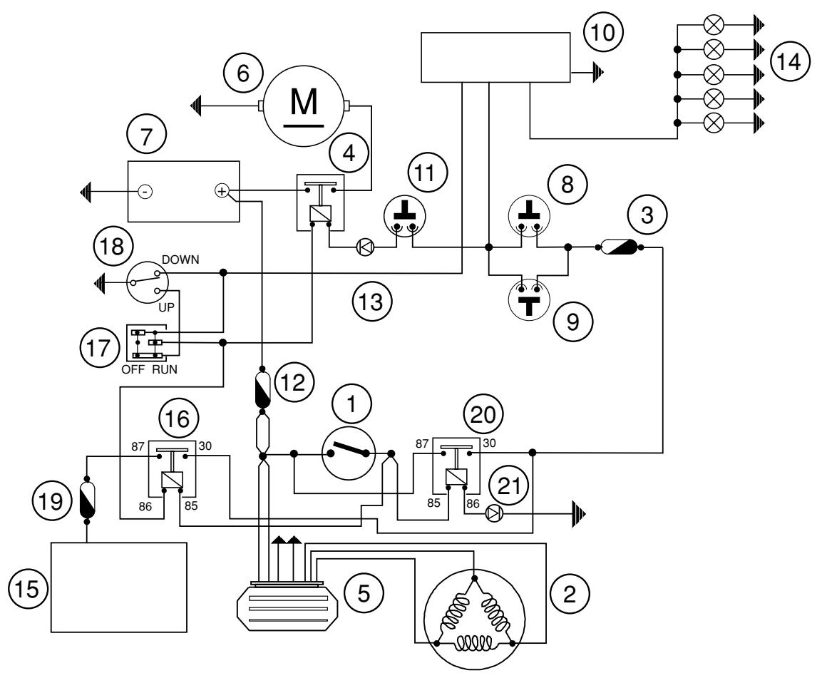
Battery recharge and starter section
04_004
| 1 | IGNITION SWITCH CONTACTS | 12 | 30A FUSE |
| 2 | FLYWHEEL MAGNETO | 13 | 6A DIODE |
| 3 | 7.5A FUSE | 14 | 5 X 12V-2.3W BRAKE LIGHT BULB |
| 4 | STARTER RELAY SWITCH | 15 | INJECTION POWER UNIT |
| 5 | VOLTAGE REGULATOR | 16 | ENGINE STOP RELAY |
| 6 | STARTER MOTOR | 17 | ENGINE STOP SWITCH |
| 7 | 12V-14Ah BATTERY | 18 | STAND SWITCH |
| 8 | FRONT BRAKE LIGHT BUTTON AND START INHIBITOR SWITCH | 19 | 5A FUSE |
| 9 | REAR BRAKE LIGHT BUTTON AND START INHIBITOR SWITCH | 20 | MAIN RELAY SWITCH |
| 10 | DIGITAL INSTRUMENT PANEL | 21 | 2A DIODE |
| 11 | START BUTTON | | |
Consent, electrohydraulic central stand device and level indicators section
04_005
| 1 | DIGITAL INSTRUMENT | 16 | 30A FUSE |
| 2 | ANALOG INSTRUMENT SET | 17 | 12V-14Ah BATTERY |
| 3 | INJECTION ELECTRONIC CONTROL UNIT | 18 | 70A FUSE |
| 4 | OUTSIDE TEMPERATURE SENSOR | 19 | STAND HYDRAULIC PUMP RELAY SWITCHES |
| 5 | WHEEL REVOLUTION SENSOR | 20 | STAND HYDRAULIC PUMP MOTOR |
| 6 | FUEL LEVEL THERMISTOR | 21 | STAND ELECTRONIC CONTROL UNIT |
| 7 | OIL PRESSURE SENSOR | 22 | STAND INHIBITOR SWITCH |
| 8 | RESET BUTTON | 23 | STAND LIMIT SWITCH |
| 9 | EMERGENCY BUTTON | 24 | BUTTON |
| 10 | 7.5A FUSE | 25 | ELECTRIC FAN RELAY SWITCH |
| 11 | IGNITION SWITCH CONTACTS | 26 | 5A FUSE |
| 12 | RADIATOR ELECTRIC FAN MOTOR | 27 | MAIN ELECTROMAGNETIC SWITCH |
| 13 | ENGINE TEMPERATURE SENSOR | 28 | 2A DIODE |
| 14 | FLYWHEEL MAGNETO | 29 | RELAY SIGNALER GLUED |
| 15 | VOLTAGE REGULATOR | 30 | 1A DIODE |
Turn indicators, horn and accessories rewiring section
04_006
| 1 | DIGITAL INSTRUMENT PANEL | 9 | 7.5A FUSE |
| 2 | TURN INDICATORS, 2 + 2 X 12V-10W BULB | 10 | 7.5A FUSE |
| 3 | TURN INDICATOR SWITCH | 11 | MAIN RELAY SWITCH |
| 4 | ACCESSORIES PREWIRING | 12 | PRESETTING FOR INTERCOM POWER UNIT INPUT |
| 5 | HORN BUTTON |
| 6 | HORN | 13 | PRESETTING FOR RADIO POWER UNIT SIDE |
| 7 | 15A FUSE | 14 | PRESETTING FOR RADIO DISPLAY SIDE |
| 8 | GNITION SWITCH CONTACT | 15 | 2A DIODE |
Control panel, warning lights, instruments
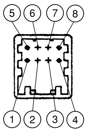
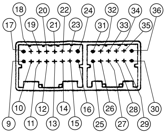
04_007
| 1 | ANALOG CARD GND | 19 | MALFUNCTIONING BRAKE LIGHT WARNING LIGHT INPUT |
| 2 | BATTERY POSITIVE TERMINAL (+30) FOR ANALOG CARD | 20 | LH TURN INDICATOR OUTPUT |
| 3 | ANALOG CARD SERIAL CLOCK OUTPUT | 21 | TURN INDICATOR STOP BUTTON INPUT |
| 4 | ANTITHEFT DEVICE LED OUTPUT | 22 | RESET SERVICE BUTTON INPUT |
| 5 | ANALOG CARD SERIAL DATE OUTPUT | 23 | COOLANT TEMPERATURE SENSOR INPUT |
| 6 | LIGHTS-ON OUTPUT | 24 | FUEL LEVEL SENSOR INPUT |
| 7 | (NOT CONNECTED) | 25 | BATTERY POSITIVE TERMINAL (+30) |
| 8 | (NOT CONNECTED) | 26 | SENSOR POWER SUPPLY |
| 9 | INJECTION WARNING LIGHT INPUT | 27 | SPEEDOMETER SENSOR EARTH RETURN |
| 10 | RELAY ALARM WARNING LIGHT INPUT GLUED | 28 | RPM SENSOR INPUT |
| 11 | MALFUNCTIONING BRAKE LIGHT OUTPUT | 29 | BATTERY POSITIVE TERMINAL (+30) |
| 12 | RH TURN INDICATOR OUTPUT | 30 | ANTITHEFT DEVICE LED |
| 13 | RH TURN INDICATOR BUTTON INPUT | 31 | KEY POSITIVE TERMINAL (+15) |
| 14 | LH TURN INDICATOR BUTTON INPUT | 32 | SPEEDOMETER SENSOR INPUT |
| 15 | HIGH BEAM WARNING LIGHT INPUT | 33 | GND |
| 16 | AIR TEMPERATURE SENSOR INPUT | 34 | AIR TEMPERATURE SENSOR EARTH RETURN |
| 17 | ENGINE START DISABLED WARNING LIGHT INPUT | 35 | HAZARD WARNING LIGHT BUTTON INPUT |
| 18 | OIL PRESSURE WARNING LIGHT INPUT | 36 | LIGHTS-ON INPUT |
Battery recharge system
The battery recharge system includes a three-phase generator with a permanent-magnet flywheel.
The generator is directly connected to the voltage regulator.
The latter is in turn directly connected to earth and to the battery positive terminal via the 30A fuse.
Therefore, the system is not connected to the ignition switch.
The three-phase generator allows considerable recharging power and a fair compromise between supplied power and slow running stability at low rpm.
Recharging system
Searching for leaks
1) Before measuring the output voltage, ensure that no electrolyte is leaking from the battery.
2) Turn the ignition key to the OFF position and connect the tester terminals between the battery negative pole (-) and the black cable.
3) Detach the black cable from the battery negative pole (-) while keeping the tester terminals connected.
4) With the ignition key still in the OFF position, the ammeter should read ≤ 0.5mA .
Checking the charging voltage
Warning - Before performing the check, ensure that the battery is in good condition.
1) Put the vehicle on the central stand.
2) With the battery properly connected to the circuit, position the multimeter prods between the battery terminals.
3) Start the engine with all lights out and rev up while measuring the voltage.
VOLTAGE: 14.0-15.0V at 5,000 rpm.
Checking the stator winding
Warning - The check can be performed with the stator in place.
1) Remove the undersaddle compartment door
2) Detach the connector between stator and regulator with the three yellow cables.
3) Measure the resistance between each of the yellow terminals and the other two.
Resistance:
0.2-1Ω
4) Check that each yellow wire is insulated from earth.
5) If the resistance is not as specified, replace the stator.
Checking the peak current
- With the engine off and swithboard "ON", turn the vehicle lights on and let the battery tension set to 12V.
- Connect the amperometric pliers to the 2 outlet recharge positive poles of the regulator.
- With lights on, start the engine and read the value on the pliers with the engine running at high speed.
With efficient battery, the measured value is: >20A
Voltage regulator/rectifier
Specifications
| ITEM | STANDARD VALUE |
| Voltage regulator/rectifier | Type | Transistorized, non-adjustable, three-phase |
| Voltage | 14 - 15V at 5000 rpm with lights off |
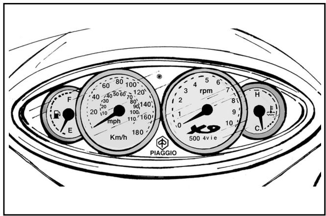
Instrument panel
The X9 is equipped with a dual instrument panel consisting of an analog section installed in the front fairing and a digital section mounted on the handlebars.
The analog section includes:
- A dual-scale (km/h-mph) speedometer controlled by the speed sensor by means of the digital section;
- A tachometer controlled by a signal coming from the power unit-injection;
- A fuel gauge controlled by a resistive sensor (in the fuel tank);
- A coolant temperature indicator controlled by a resistive sensor (on the cylinder head).
These instruments are of the electrical type, and are operated by step-by-step motors.
04_009
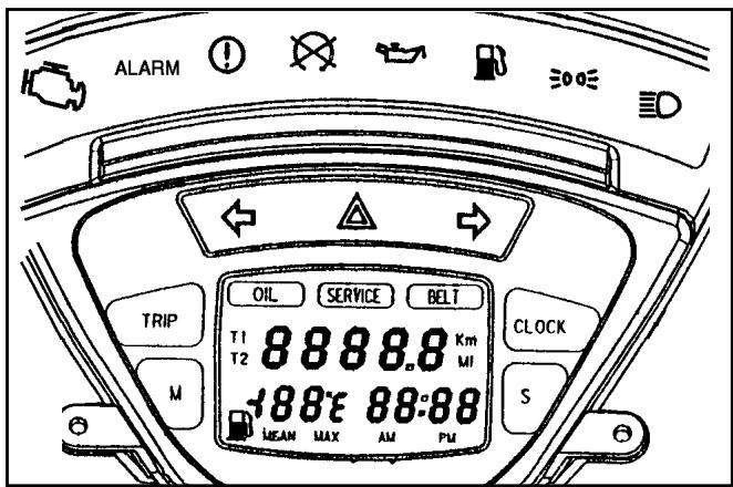
The digital section includes the following indicators:
- Reserve fuel warning light: amber.
- Lights-on and low beam warning light: green.
- High beam warning light: blue.
- Left-hand turn indicator warning light: green.
- Right-hand turn indicator warning light: green.
- Hazard warning lights (four turn indicators): red
- Engine disabled: red.
- Brake light bulb burnt-out warning light: red.
- Oil pressure warning light: red;
- Injection warning light: amber;
- ALARM warning light (electrohydraulic cable): red.
04_010
The reserve fuel, turn indicator and hazard warning lights are activated by the electronics of the instrument. For example, the fuel reserve warning light comes on only when the reserve fuel indication from the fuel tank lasts a minimum of 13.5 seconds. This prevents the warning light from blinking when the engine begins to run on reserve fuel.
- The flashing function is built in the electronics of the instrument, which allows the hazard warning lights to work when the ignition switch is in the "OFF" position and the control switch is disabled. The control switch is active only when the instrument panel is on.
For greater riding safety, the "turn indicator control" function is connected to the mileometer. If the turn indicators are inadvertently left on, they are automatically switched off after 1 kilometre.
- The "engine start disabled" warning light is activated by the standby switch and the emergency switch on the right side of the handlebar.
- The indication "brake light bulb burnt-out" is activated when at least two of the five bulbs fail to operate.
- The warning light is controlled by a circuit that measures the absorption of the brake light bulb.
- The liquid crystal display shows a 5-digit total mileage count in either kilometres or miles. Naturally, this counter can never be reset. To select the unit, with key turned to “OFF”, press the “Trip” and “M” buttons at the same time and turn the ignition switch to the “ON” position. If the two buttons are depressed for longer than three seconds, the word “SET” is displayed and then the unit toggles between kilometres and miles.
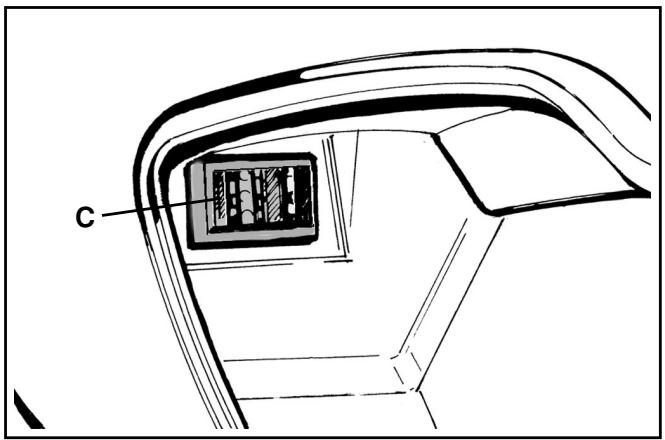
3 Four fuses «C» in the glove compartment, on the left side.
| Fuse | Protected circuits |
| 1 x 15 A | Flash, horn, accessories |
| 1 x 7.5 A | Brake light buttons, start button, starter relay switch |
| 1 x 7.5 A | Lights switch, parking lights, number-plate light |
| 1 x 7.5 A | Digital instrument panel, PICS control unit power supply |
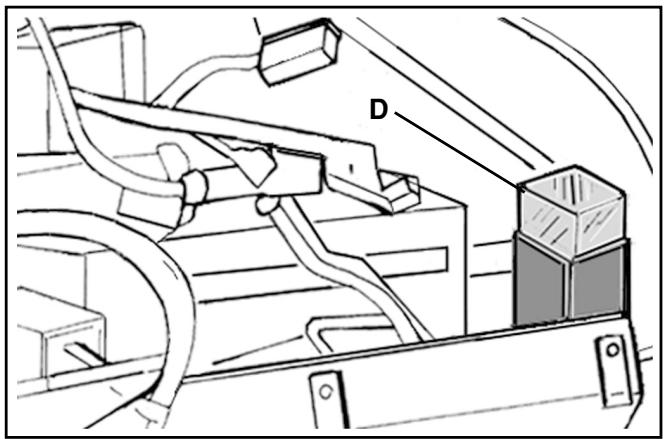
4 One fuse «D» of 30A (main fuse) located next to the battery on the solenoid starter. A spare fuse is also provided underneath.
04_016
04_017
List of bulbs
| Function | Type | Power |
| Low beam bulb | halogen | 12V-55W |
| High beam bulb | halogen | 12V-55W |
| Front parking light bulb | all-glass | 12V-5W x 2 |
| Front turn indicator bulb | spherical | 12V-10W x 2 |
| Rear parking light bulb | spherical | 12V-5W x 2 |
| Brake light bulbs | spherical | 12V-2.3W x 5 |
| Rear turn indicator bulb | spherical | 12V-10W x 2 |
| Instrument panel lighting bulb | all-glass | 12V-2W x 5 |
| Glove compartment lamp bulb | cylindrical | 12V-5W |
| Number-plate light bulb | cylindrical | 12V-5W |
Battery (12V - 14Ah)
Caution
- The battery electrolyte causes severe
burns as it contains sulphuric acid. Avoid contact with the eyes, the skin and clothing.
In case of contact with the eyes or the skin, rinse generously with water for about 15 minutes and immediately seek medical attention.
In case of ingestion, immediately drink large quantities of water or milk. Subsequently administer milk of magnesia, beaten eggs or vegetable oil. Immediately seek medical attention.
Batteries produce explosive gases. Keep them away from open flames, sparks and cigarettes. If the battery is charged in a closed place, ensure adequate ventilation.
Always protect the eyes when working close to batteries.
Keep out of reach of children.
Installing charged-dry batteries:
1) - Remove the short closed tube and the plugs. Fill the cells to the upper level with accumulator sulphuric acid, specific weight 1.26, corresponding to 30^ Bé at a temperature of at least 15^ .
2) - Leave at rest for at least two hours and then restore the level by adding sulphuric acid.
3) - Recharge within 24 hours by means of the specific charger 020333Y (single station) or 020334Y (multiple station) with intensity equal to about 1/10 of the battery rated power, until the acid density reaches the value of about 1,27, corresponding to 31 Bé, and until such values have stabilized.
4) - When the charging is over, level off the acid (by adding distilled water), put the plugs back into place and clean thoroughly.
5) - Proceed to install the battery on the vehicle, taking care to observe the connections described at item 3) of the paragraph Recharging the battery.
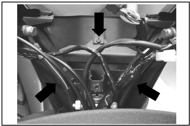
Removing and installing the battery
- Lift the saddle;
- Remove the rear optical unit and the covering element;
- Disconnect the battery by detaching the negative (-) cable first and then the positive (+) cable.
- Remove the battery strap and then the battery itself.
-
To install the battery, follow these steps:
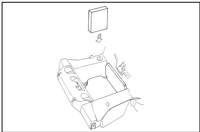
-
Fit the lower support shown in the figure on the battery compartment bottom.
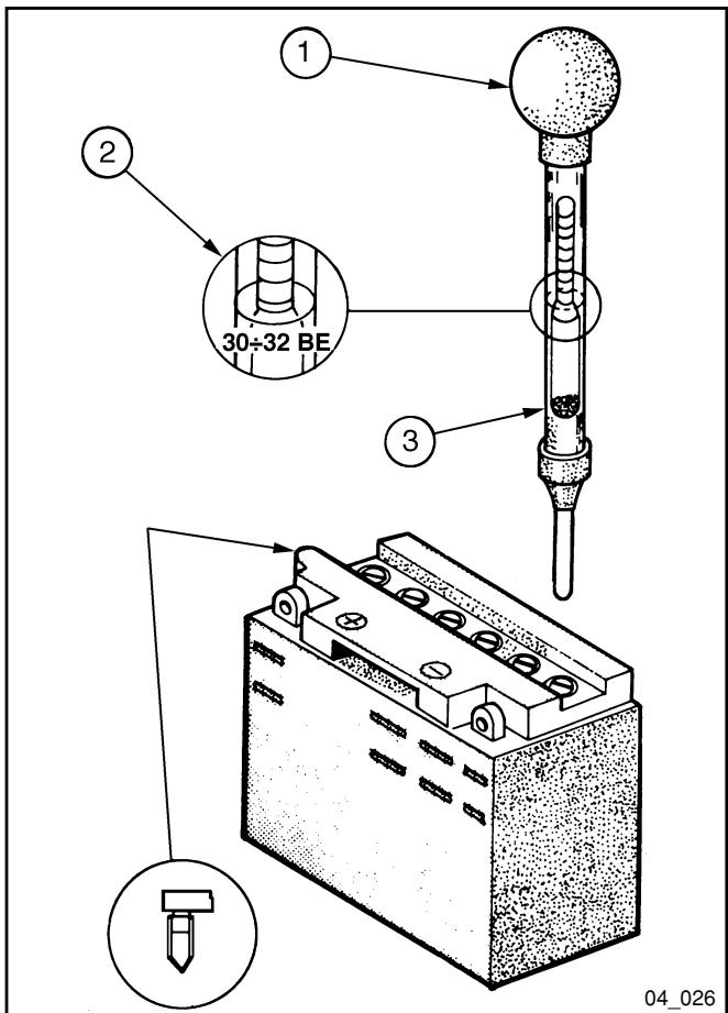
| 1 | Hold tube upright |
| 2 | Check visually |
| 3 | Float must be disengaged |
04_019
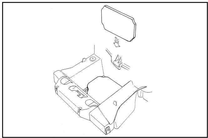
- At last, fit the left side element.
04_020
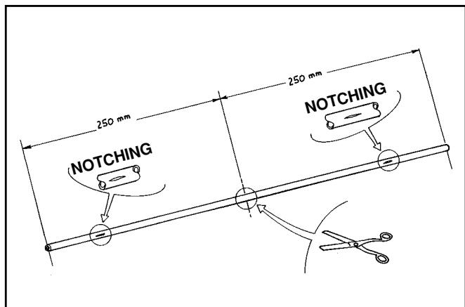
- Cut the breather pipe supplied as shown in the figure.
04_021
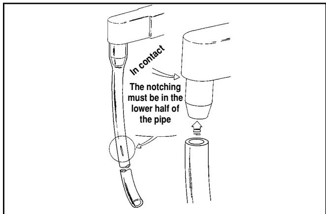
- Fit the pipe until it contacts the battery and in the direction shown in the figure.
04_022
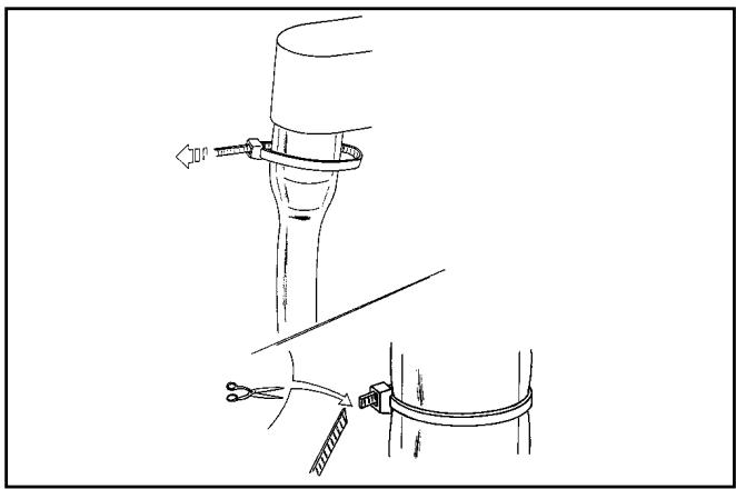
- Lock the pipe with a tear-clamp and cut the end that sticks out of the clamp.
04_023
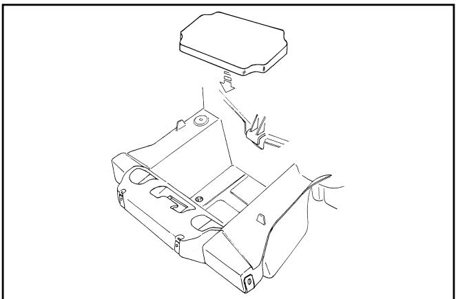
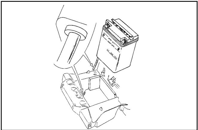
- Insert the battery in the compartment taking care to fit the breather pipe in the bottom hole.
04_024
- Insert the battery in the compartment taking care to fit the breather pipe in the bottom hole.
04_025
Checking the electrolyte level
Frequently check that the electrolyte reaches the upper level. To top up, only use distilled water.
If you need to top up the battery too frequently, check the vehicle electrical equipment as the battery is certainly working in overload conditions, which will lead to rapid deterioration.
Checking the battery charge
After restoring the electrolyte level, check its density with the special hydrometer (see figure).
When the battery is charged, electrolyte density must be between 30 and 32 Bé, corresponding to specific gravity of 1.26-1.28 at a temperature not lower than 15^ . If density has fallen below 20^ Bé, the battery is completely discharged and needs recharging.
If the vehicle is not used for some time (1 month or more) the battery must be periodically recharged. In three months the battery runs down completely.
When refitting the battery take care not to invert the connections: the ground lead (black) is to be connected to the negative (-) terminal and the other lead (red) must be connected to the positive (+) terminal.
Battery recharge
- Before charging the battery remove all cell plugs. Keep free flames or sparks away from the battery during recharge. When the battery has to be removed from the vehicle, disconnect the negative terminal first.
Charge the battery using the specific charger 020333Y (single station) or 020334 (multiple station), by putting the charger selector on the type of battery to be recharged (use current at 1/10 of the battery rated power). Connection to the power supply must be made by means of the corresponding poles (+ with + and - with -).
4) Cleaning the battery
Keep the battery clean, especially the top; coat the terminals with Vaseline.
Warning - Never use fuses having a greater capacity than the one recommended. The use of a fuse of unsuitable capacity may result in serious damage to the whole vehicle or even cause a fire.
Warning - Normal drinking water contains salts that are harmful for batteries. Use only distilled water.
Warning - To ensure maximum performance the battery must be charged before using the vehicle. Failure to properly charge the battery before starting the vehicle will cause the battery premature breakdown.
Sealed battery
Putting a sealed battery into service
If the vehicle is equipped with a sealed battery, servicing is limited to checking the charge level and, if necessary, recharging the battery.
These operations must be performed during predelivery, and every six months of open-circuit storage.
Therefore, in addition to checking and, if necessary, charging the battery before delivery, it is necessary to carry out these operations before storing the vehicle, and subsequently every six months.
RECHARGING THE BATTERY FOLLOWING OPEN-CIRCUIT STORAGE
1) Checking the voltage
Before installing the battery on the vehicle, measure the open-circuit voltage with an ordinary multimeter.
- If the voltage exceeds 12.60V , the battery can be installed without recharging.
- If the voltage is less than 12.60 ~V , recharge the battery as described at item 2).
2) Constant-voltage charging method
- Constant voltage: 14.40-14.70 V
- Initial charging current: 0.3 - 0.5 × rating
- Charging time: Recommended 10-12 hrs
Minimum 6 hrs
Maximum 24 hrs
3) Constant-current charging method
- Initial charging current: 1/10 of rating
- Charging time: Maximum 5 hrs
Caution
- When the battery is deeply discharged
far below 12.6V), 5 hours' recharging may not be enough to obtain optimum performance.
In these conditions, however, to avoid damaging the battery beyond repair, it is essential not to recharge it for more than 8 consecutive hours.
TABLE OF CONTENTS
ENGINE
Engine disassembly from frame
Caution - Perform these operation with the engine cold.
- Disconnect the battery.
- Remove the saddle, and the upper and lower body sides (Chapter 8 - Bodywork)
- Drain the coolant (Chapter 3 - Maintenance)
- Disassemble the muffler assembly and relevant support, as described below.
- Remove the rear wheel (Chapter 6 - Front/Rear Suspension)
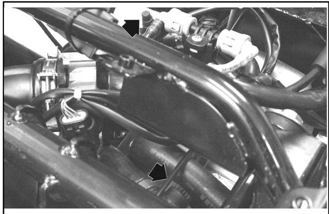
- Remove the accelerator control transmissions and mark their position on the throttle body control.
- Disconnect the air filter sleeve and the engine oil values collecting pipe.
- Disconnect the earth cable from the engine.
- Disconnect the electrical devices from the throttle body, head, and starter feed cable.
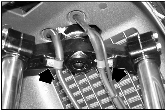
- Detach the fuel delivery and return pipes to the injector and the coolant system pipes (head outlet and thermostat input)
- Close the injector Tee Joint with rubber plugs to prevent dirt from entering.
- Detach the H.V. cable from the spark plug.
- Detach the generator harness from the vehicle electrical system.
Caution - Take care when handling the petrol.
Warning - When installing the battery, first fix the positive cable and then the negative cable.
Muffler assembly disassembly
- Unloose the two fixings of the exhaust manifold on the head.
05_001
- Unloose the 3 screws fixing the muffler to the supporting arm.
- Remove the muffler assembly.
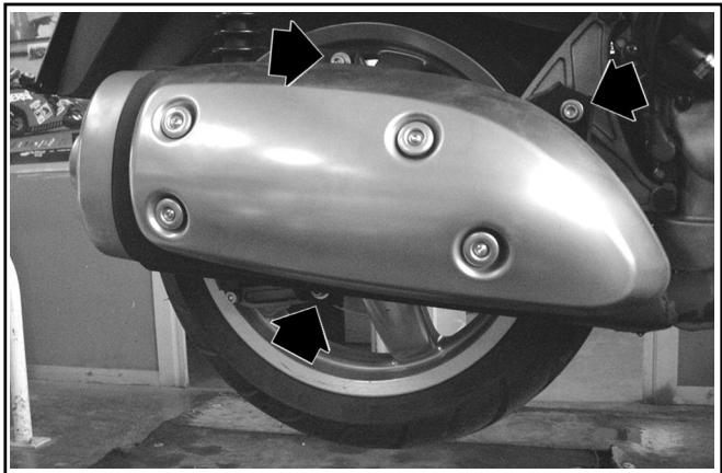
05_002
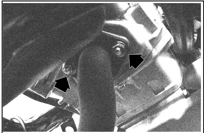
Supporting arm disassembly
- Unscrew and remove the r.h. shock absorber to supporting arm lower fixing bolt
- Unloose the arm to engine 2 fixing screws.
- Remove the split pin and unscrew the wheel axle nut; avoid the wheel turning by means of the integral brake.
- Remove the supporting arm.
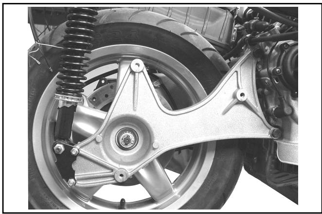
05_003
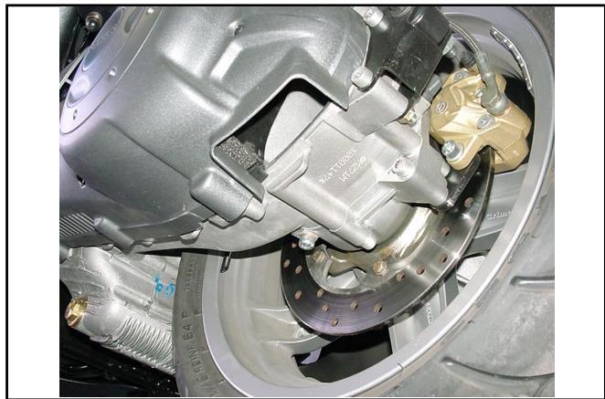
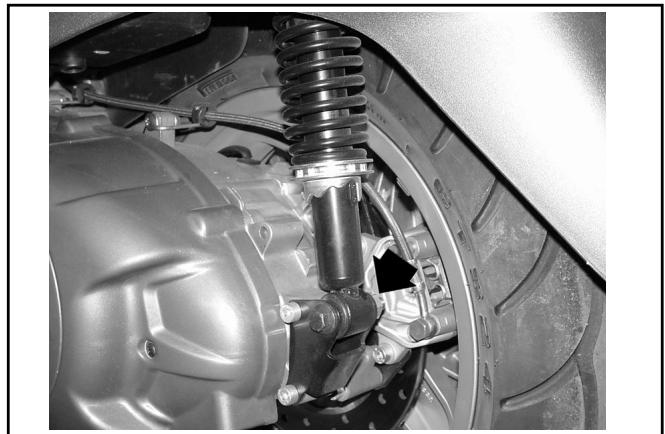
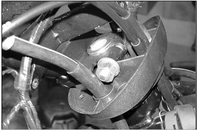
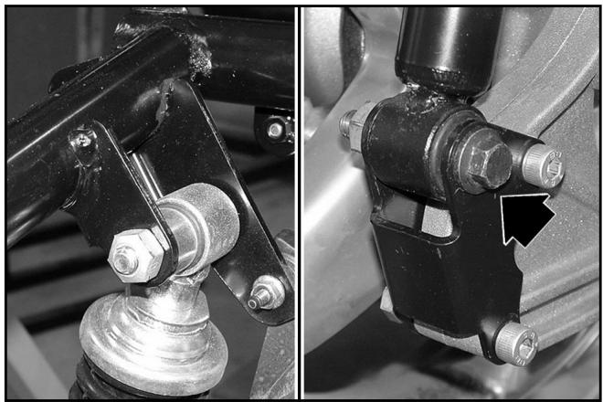
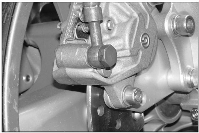
Disassembly of I.h. shock absorber lower pin
- Remove the bolt shown in the figure.
N.B.: To be able to remove the shock absorber support, remove the two nuts on the brake caliper side and the screws.
05_004
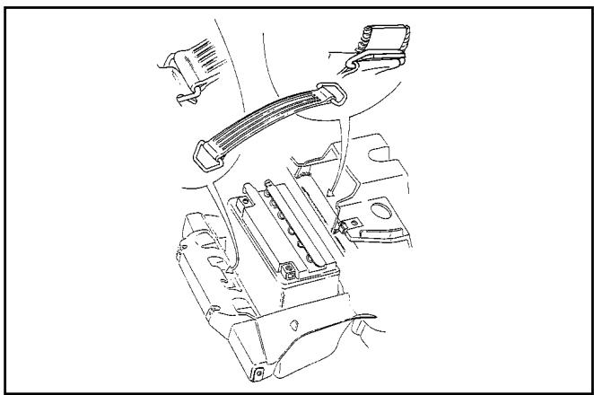
Engine pin/swing arm disassembly
- Adequately support the engine.
- Remove the nut shown in the figure.
- Remove the pin.
- Now the engine is free.
05_005
Engine assembly to vehicle
- Perform the assembly in the reverse order observing the tightening torques indicated in Chapter 1.
Warning - Take care not to invert the position of the two accelerator control transmissions. Check that both show a slight play with the valve in contact with the register.
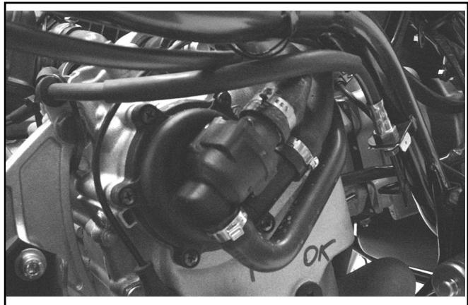
N.B.: Carefully clean the injector Tee Joint before reassembling the quick-connections. Direct the injector in such a way as to avoid any interferences of the electrical cables with the coolant and fuel pipes.
- Check the engine oil level, top up if necessary with oil of the recommended type.
- Fill the cooling system (Chapter 11-Cooling).
- Check the accelerator and electrical devices function.
Handlebar
Removal
- Begin by removing the radio-interphone and then disconnect the feeder cable.
- Remove the digital panel support and the front and rear sections of the handlebar cover as described in Chapter 8-Bodywork.
- Disengage the handlebar from the components installed on it.
- Remove the two counterpoises after loosening the side screws.
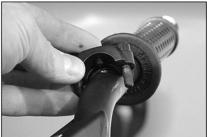
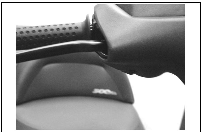
- Remove the pumps after loosening the screws on the clevises shown in the figure.
- Slide the throttle control off the handlebar after loosening the fixing screws.
- Remove the left handgrip.
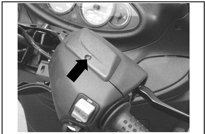
- Loosen the bolt fastening the handlebar to the steering tube shown in the figure and then remove it. Remove the handlebar and the plastic support.
Note: If the handlebar is removed to proceed to the removal of the front fork, simply overturn the handlebar onto the front of the vehicle without removing the parts fitted on it. Take care not to damage the flexible transmissions, the pipes or the bodywork.
Fitting
Perform the removing procedure in reverse order. To align the handlebar with the steering tube, align the notch on the handlebar with the notch on the steering tube. Tighten the fasteners with the torques specified in Chapter 1.
Tightening torques:
Handlebar fastening bolt: 43 - 47 N·m
06_001
06_002
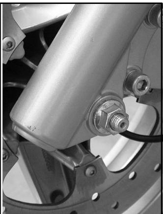
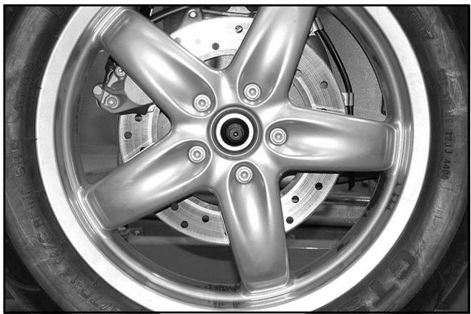
Removing the front wheel
- Remove the two brake calipers as described in Chapter 7-Braking system.
- Unscrew the axle locknut.
- Disengage the axle by loosening the two screws on the right-hand fork sheath (see figure).
- While supporting the wheel, remove the axle on the right side of the vehicle.
Caution - When removing the wheel, take care not to damage the speed sensor.
06_003
Overhauling the front wheel
Check the bearings for any excessive play or stickiness causing noise and uneven rotation of the wheel.
Should the wheel bearings need to be replaced, follow these steps:
- Using a suitable extractor on the inner race, remove the two bearings on the left side of the wheel (speed sensor side).
06_004
- Support the wheel to allow the removal of the internal parts.
- Using a mallet and a drift of suitable diameter, simultaneously drive out the inner spacer, the right-hand bearing and the outer spacer complete with the dust ring on the same side.
06_005
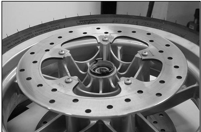
- Refit the two bearings on the left side of the wheel rim.
- Using a tube of suitable diameter on the outer race of the bearings, push them home into their seats.
- Fit the spacer in the right side of the wheel as shown in the figure.
- Fit the right-hand bearing by following the same procedure as the other bearings.
06_006
- Refit the two front brake discs as described in Chapter 7-Braking system.
- Fit the outer spacer and the related ring taking care not to compress it excessively against the wheel bearing.
06_007
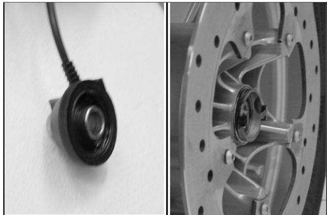
- Check the condition of the speed sensor seal ring and of the related groove in the wheel rim.
- Insert the pin from the r.h. side by aligning the spacers.
- Take care not to damage the phonic wheel.
- Offset the drives beforehand by about 90^ .
- Tighten the wheel axle nut.
- Tighten the two screws of the clamp on the pin housing, on the r.h. sheath.
Tightening torques:
Axle nut: 45 - 50 N·m
Right-hand sheath lower screws: 6 - 7 N·m
06_008
Removing the front fork
- Remove the mudguard as described in Chapter 8-Bodywork.
- Remove the handlebar and the front wheel as previously described.
- Loosen the two screws fastening the brake line supports (see figure).
Note: It is also possible to remove one of the two fork rods after loosening the two related screws on the fork upper plate.
06_009
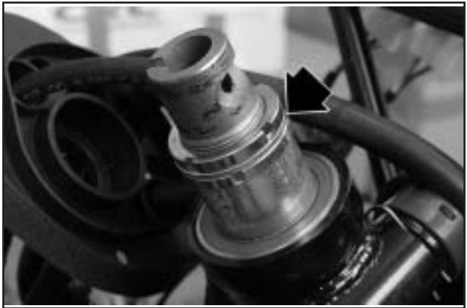
- Remove the two rings, the middle washer shown in the figure and the spacer below.
Caution - Adequately support the vehicle so as to allow the steering tube to come out of the head tube.
Warning - Before unscrewing both rings, support the fork assembly so as to prevent it from falling.
- Pull out the fork assembly.
Specific tool:
Steering tube ring spanner: 020055Y
06_010
Replacing the steering bearings
- Using the specially designed tool shown in the figure and a mallet, remove the upper ball bearing.
N.B.: Act at different times between the two points at 180^ . Failure to observe this instruction may damage the housing.
Specific tool:
Steering thrust ring removing drift: 020004Y
06_011
- Use the same method to extract the seat of the lower roller bearing.
N.B.: Act at different times between the two points at 180^ . Failure to observe this instruction may damage the housing.
Specific tool:
Steering thrust ring removing drift: 020004Y
06_012
- Remove the lower roller bearing and the dust cover ring from the fork by means of the specific tool.
- Use the larger half ring pair and the shorter steering tube protection.
06_013
Steering tube lower bearing extractor: 020458Y
Fitting the steering bearing
- Check the condition of the bearing races and rollers.
- Fit the upper bearing and the lower bearing housing by inserting the specific tool in the steering sleeve, provided with 2 adapters.
- Fit the dust cover ring and the roller bearing on the steering tube by means of a piece of tube having a suitable diameter, and by resting against the inner race of the roller bearing.
Steering seats assembly tool: 001330Y
Upper bearing adapter: 001330Y010
Lower bearing adapater: 001330Y009
06_014
- Lubricate the steering bearing housing with grease of the TUTELA Z2 type.
- Fit the steering tube into the sleeve.
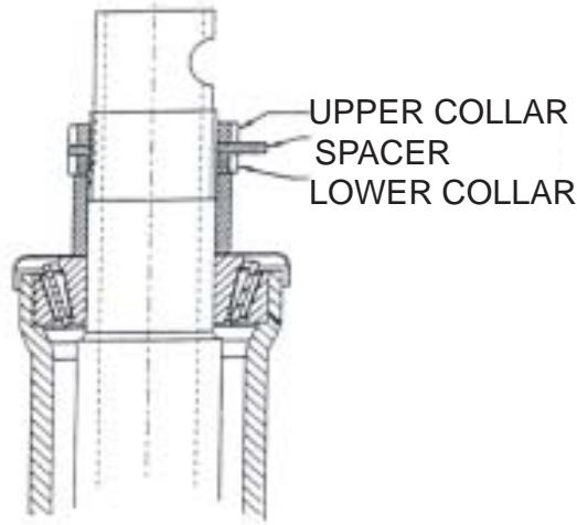
- Tighten the lower collar with a torque of 20-25 Nm (2-2.5 Kgm) and then loosen it completely.
- Tighten it again with a torque of 10 - 13 Nm (1-1.3 Kgm), then loosen it by 90 degrees.
- Insert the spacer.
- Lock the upper collar with a torque of 30-36Nm (3-3.6 Kgm).
Wrench for Steering Tube Collar - 020055Y
N.B.
This procedure is also valid for the previous versions with upper ball bearing.
06_010
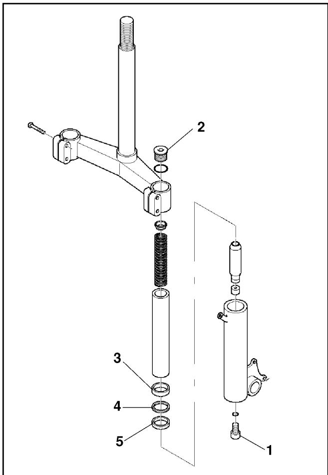
Replacing the seal ring and removing the fork rod
- Remove lower screw (1).
- Drain the oil from the suspension.
- Remove the fork rod.
- Replace seal rings (3), (4) and (5) with new ones.
- Fit the new rings after lubricating their seats.
- Reinsert the fork rod;
- Unscrew plug (2);
- Fit from the top a suitable wrench of 12mm in order to block the pumping element. Refit the lower screw (1).
- Pour in 90 cc of "Fork PG" SAE 20W oil;
- Reassemble by following the reverse procedure.
06_015
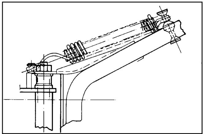
Rear shock absorbers
Removal
Follow these steps:
- Put the vehicle on the central stand.
- Using a jack, slightly lift the engine so as to free both shock absorbers.
- Remove the silencer.
- Unloose the shock absorber spring assembly fixing screw from the support fixed to the engine, on one side, and from the one fixed to the muffler support, on the other side;
- Unscrew the two upper nuts (one on each side) fixing the shock absorber spring assemblies to the frame and then remove the assemblies themselves.
Fitting
Perform the removing procedure in reverse order taking care to observe the prescribed tightening torques.
Tightening torques:
Shock absorbers lower fixing screw: 33 - 41 N·m
Shock absorbers upper fixing screw: 33 - 41 N·m
06_016
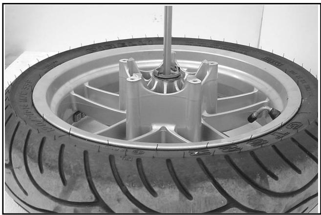
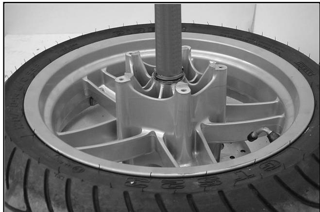
Rear wheel
Removal
- Remove the shock absorber as previously described.
- Remove the silencer and the bracket as described in Chapter 5-Engine.
- Remove the 5 screws fixing the rear wheel to the hub.
- Take down the wheel.
Fitting
Fit the wheel using the reverse procedure to the removal. Tighten the rear wheel fixing screws and the axle locknut with the prescribed torques.
06_017
Tightening torque:
Rear wheel rim screws: 20 - 25 N·m
Central stand (Basic model)
Removal
- Release the springs.
- Unloose the r.h. and l.h. nut.
- Remove the screws.
Fitting
Perform the above procedure in reverse order and then move the seal rings into their seats.
06_018
Warning - Lubricate the following parts with TU-TELA Z2 grease: spring connection pins, bushes on stand clamps.
Tightening torques:
Central stand bolt: 25 - 30 N·m
06_019
TABLE OF CONTENTS

LUBRICATE WITH OIL

LUBRICATE WITH GREASE

APPLY PRODUCT

CLEAN CAREFULLY

WARNING - HANDLE WITH CARE

ALWAYS REPLACE
| CALLOUT | A | B | C | D | E | F | G | H | I | L | M | N | O | | | |
| QUANTITY | 6 | 4 | 3 | | 1 | 1 | 1 | 2 | | | 2 | 10 | 5 | | | |
| TORQUE N·m | 20-25 | 42-62 | 15-20 | | 20-25 | 20-25 | 16-20 | 16-20 | | | 20-25 | 5-6,5 | 14-17 | | | |
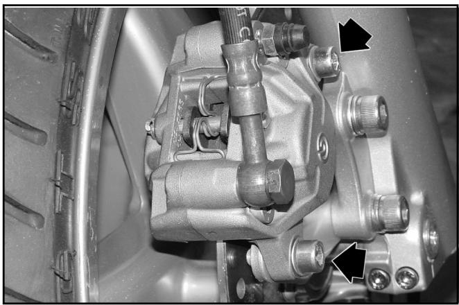
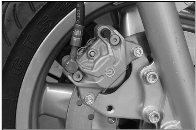
Checking and replacing the brake pads
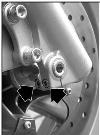
Removing the front brake pads:
Follow these steps:
- Loosen the two screws shown in the figure and disengage the calipers from their supports.
- Remove the retaining ring and the pin. During the operation pay special attention to the pin retaining spring as it may spring off abruptly.
- Remove the two pads by pulling them downwards.
- Check the thickness of the pads.
Wear limit: 1.5mm
- Repeat the operations on the brake caliper on the opposite side.
07_001
To fit the pads, follow these steps:
- Insert the two pads into the caliper.
- Fit the pin retaining spring.
- Press down the spring to allow the insertion of the pin (see figure).
- Insert the pin.
- Fit the retainer.
- Fit the caliper on its support and then tighten the two screws with the prescribed torque.
Tightening torques:
Screws fixing caliper to support: 20 - 25 N·m
N.B.: If during the assembly it is not possible to fit the caliper on the disc, refit the pistons in the caliper carefully.
07 002
Removing and replacing the rear brake pads
Follow these steps:
- Remove the left-hand rear shock absorber support with the shock absorber itself and the rear wheel as described in Chapter 6-Front and rear suspensions.
- Unloose the two screws fixing the brake caliper support to the engine.
- Remove the caliper from its support.
- Remove the retaining ring and the pin.
- Remove the two pads by pulling them downwards.
- Check the thickness of the pads.
Wear limit: 1.5mm
- If the thickness of the pads is less than the prescribed limit, replace them.
- Refit the parts by following the same procedure used for the front brake pads.
- Tighten the two screws fixing the caliper support to the engine with the prescribed torque.

07_003
Tightening torques:
Screws fixing caliper to support: 20 - 25 N·m
Screws fixing caliper support to engine: 20 - 25 N·m
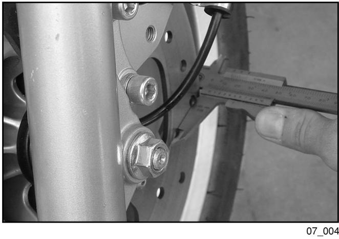
Brake discs
Checking disc thickness
It is important to check the brake discs. The discs should always be perfectly clean and free from rust, grease and dirt and shown no deep scoring.
Thickness of front discs when new 4.0 mm
Thickness of rear disc when new 5.0 mm
Wear limit (front discs) 3.5 mm
Wear limit (rear) 4.5 mm
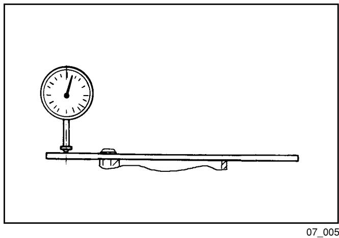
Checking disc distortion
Take down the wheel and, using suitable equipment, check that the axial runout of the braking surface does not exceed the specified limit.
Max. axial runout: 0.1mm
If the runout exceeds the specified limit, replace the disc as described below and repeat the measurement.
If the problem persists, check and if necessary replace the wheel hub.
Note: When refitting, thoroughly clean the disc and its seat on the hub.
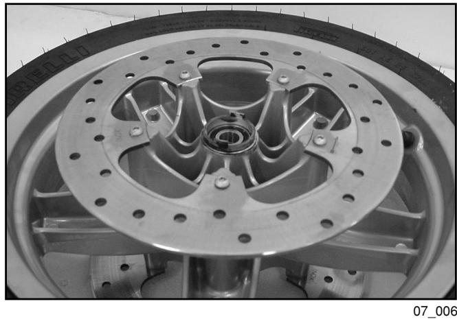
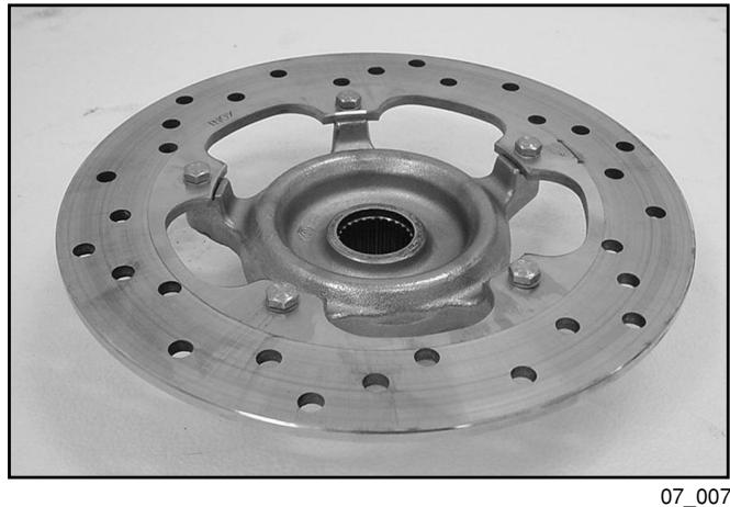
Replacing the front brake discs
Follow these steps:
- Remove the front wheel as described in Chapter 6-Front and rear suspensions.
- For each disc, loosen the five screws shown.
- Carefully clean the seats on the front wheel hub and the discs.
- When fitting the disc, take care to position it properly by referring to the arrow stamped on it.
- Tighten the screws with the prescribed torque and smear them with LOCTITE Threadlocker medium 242.
Note: The disc side bearing the arrow indicating the direction of rotation must face the outside of the vehicle.
Tightening torques:
Brake disc fixing screws: 5 - 6 N·m
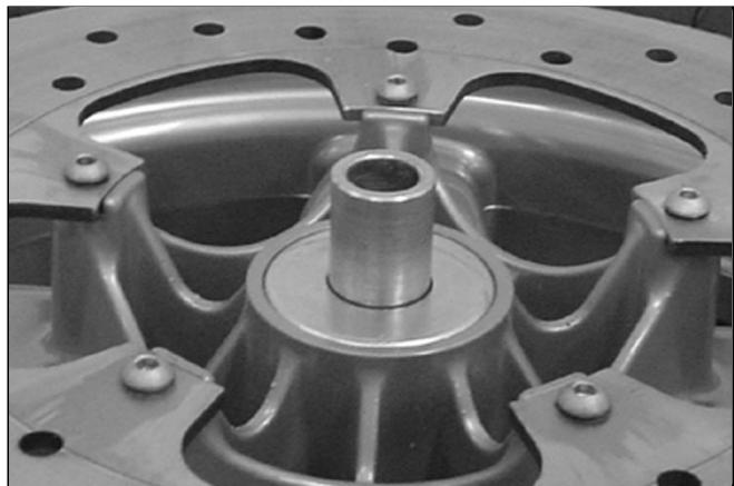
Replacing the rear brake disc
- Remove the rear wheel as described in Chapter 6-Front and rear suspensions.
- Remove the hub with the brake disc.
- Follow the same procedure used for the front brake discs.
Note: The disc side bearing the arrow indicating the direction of rotation must face the outside of the vehicle.
Tightening torques:
Brake disc fixing screw: 14 - 17 N·m
General guidelines for servicing the hydraulic braking system
Caution - The brake fluid is corrosive. Always wear protective gloves when working on the hydraulic system. In case of contact with the eyes, rinse generously with water.
The used brake fluid is harmful to the environment. Collect and dispose of used oil according to the regulations in force.
Under normal climatic and riding conditions the brake fluid should be renewed every two years. However, if the brakes are subjected to heavy stress the fluid should be renewed at shorter intervals.
When reassembling, reused parts should be perfectly clean and free from oil, diesel fuel and grease. It is therefore necessary to thoroughly clean them with denatured alcohol. Braking system.
Note: When topping up or renewing the brake fluid, only use DOT4 - NHTSA 116 fluid.
Always ensure that all parts are perfectly clean.
The brake fluid is highly corrosive. Take care not to spill it on painted surfaces.
The brake fluid is hygroscopic, i.e. it absorbs humidity from the air. If the humidity contained in the fluid exceeds a given concentration, the braking action becomes insufficient owing to a reduction in the boiling point of the liquid.
Note: Always take the brake fluid from sealed containers.
Note: Rubber parts must not be left immersed in alcohol for longer than 20 seconds. After the washing, dry the parts with a compressed air jet and wipe them with a clean cloth.
Seal rings must be immersed in the liquid of use. The use of the PRF1 protective agent is permitted.
Caution - The braking action is decreased if brake fluid is present on the brake discs or pads. Should the discs and the pads become contaminated with brake fluid, replace the pads and clean the disc with a good-quality solvent.
Renewing the brake fluid and bleeding air from the brake circuit Front brake
Follow these steps:
1) Put the vehicle on the stand on level ground.
2) Remove the brake fluid pump reservoir cap as described in Chapter 8-Bodywork.
3) Remove the two screws shown in the figure and open the front brake fluid reservoir.
4) Using the bleeder screw on the brake caliper, empty the brake circuit through a pipe of suitable diameter.
5) Collect the used fluid in a suitable container.
6) Operate the brake pump until all the fluid has come out.
7) Close the bleeder valve.
8) Fill the circuit reservoir to the maximum level with fluid of the prescribed type.
9) Attach the pipe of the specific tool (Mityvac-type manual pump) to the bleeding connection.
10) While acting on the bleeder with the specific tool, constantly pour fresh fluid into the reservoir so as to avoid sucking in air. Stop pumping as soon as the fluid flows out of the bleeder with no air bubbles.
11) Tighten the bleeder screw with the prescribed torque.
Tightening torque:
Drain screw: 12 - 16 N·m
07_008
Note: If air keeps coming out during the bleeding, check all connections. If these are tight, check the different pump seals and the caliper pistons.
During the operation oil may trickle from the bleeder screw onto the caliper and the disc. In that case, carefully dry the caliper and degrease the disc.
Specific tool: Vacuum pump MITIVAC type: 020329Y
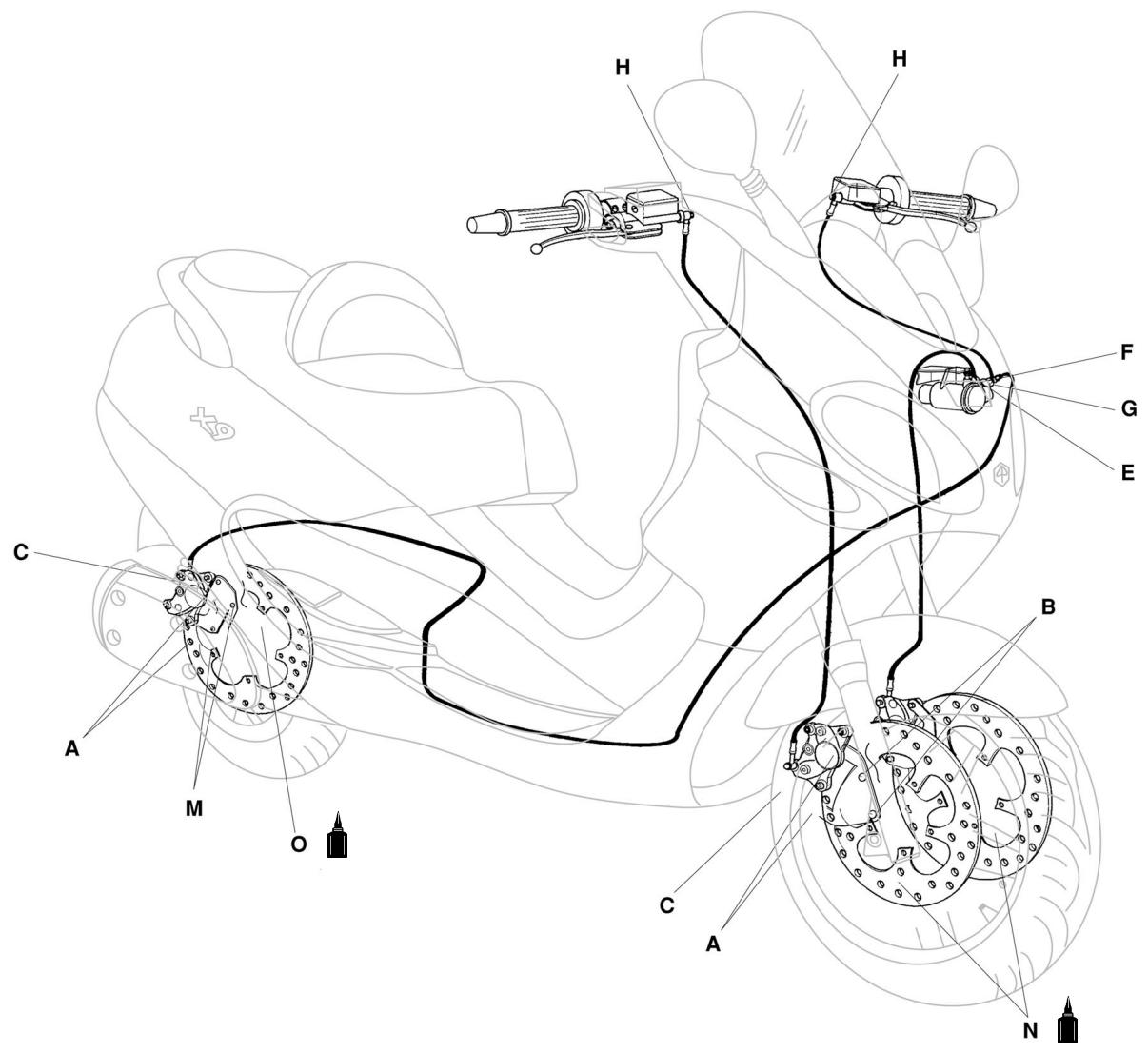
Combined brake
A control system allows the left brake lever to simultaneously operate the left-hand front caliper and the rear caliper.
To empty the circuit, follow the procedure given for the right-hand front brake, using the bleeder of both brake calipers, front and rear.
To bleed the system, follow these steps:
1) Attach the specific Mityvac tool to the bleeder fitted on the pressure divider valve shown in the figure.
2) Fill the left brake fluid reservoir to the maximum level.
3) Slowly operate the left brake lever while pouring fresh fluid into the reservoir until all the air has come out, thus obtaining the bleeding of the first section of the combined brake line. Tighten the bleeder valve with the prescribed torque.
4) Proceed to bleed each caliper - the front caliper first and then the rear caliper - following the same procedure used for the front brake.
Specific tool: Vacuum pump MITIVAC type: 020329Y
Tightening torque: Oil drain screw: 12 - 16 N·m
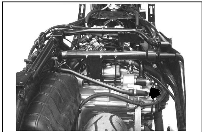
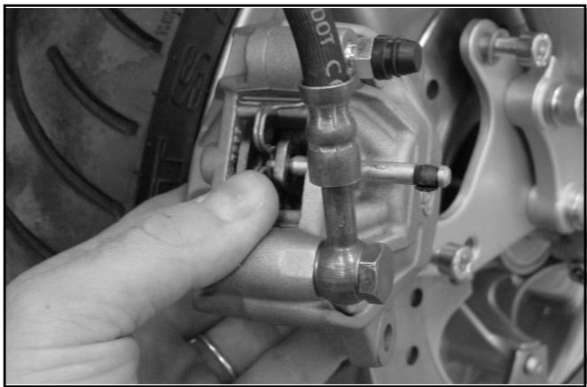
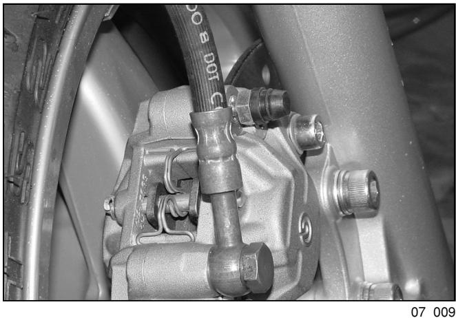
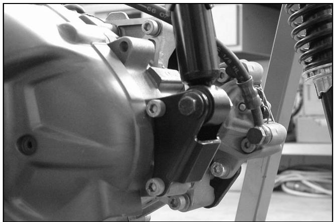
Removing the brake calipers
Check the condition of the brake lines, the gaskets and the related connections. Should any fluid leak onto the calipers, replace them by following these steps:
- Empty the circuit as previously described for the brake fluid renewal.
- Remove the caliper pipe connection shown in the figure.
- Collect any fluid residues left in the pipe.
- Remove the two screws fixing the caliper to the support.
- Remove the caliper.
- Remove the brake pads from the caliper as previously described.
- Replace the caliper with a new one and then follow the reverse procedure to the removal.
Note: Fit new copper gaskets on the connection.
- Tighten the two fixing screws with the prescribed torque.
- Complete the operation by filling and bleeding the circuit.
- Use the same procedure for the three calipers, the only difference being that the rear brake caliper must be removed from the vehicle together with its support. This is obtained by loosening the two screws shown in the figure after removing the rear wheel as described in Chapter 6-Front and rear suspensions.
Tightening torque:
Screws fixing caliper to support: 20 - 25 N·m
07_011
07_012
07_013
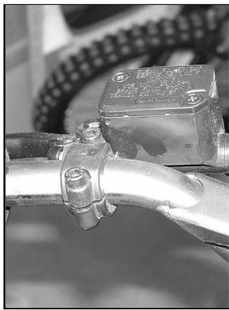
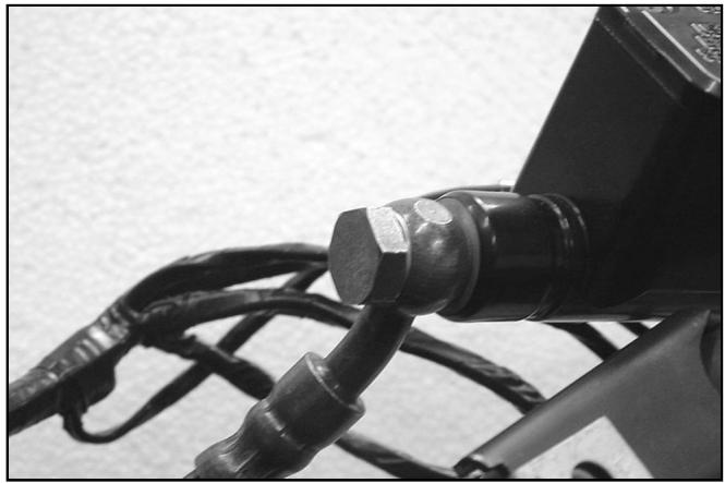
Removing the brake pumps
To remove and replace the brake pumps, follow these steps:
- Empty the related braking circuit as described in the previous paragraphs.
- Remove the connection shown in the figure taking care to prevent any fluid residues from coming out.
- Remove the two screws fastening the clevis to the handlebar.
- Replace the broken pump.
- Reassemble taking care to replace the copper gaskets. Fasten the connection and tighten the two screws fixing the pump to the handlebar.
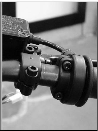
07_014
Note: Take care to properly insert the specially designed projection on the pump clevis in the related hole in the handlebar (see figure).
- Complete the overhaul by filling and bleeding the circuit.
- The removing procedure is the same for both brake pumps (see figure).
07_015
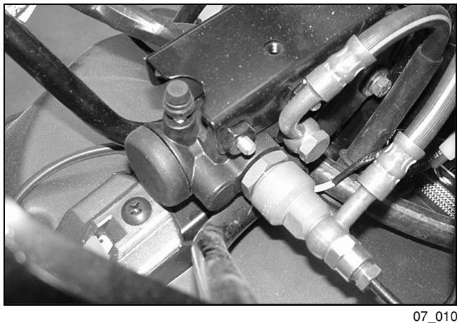
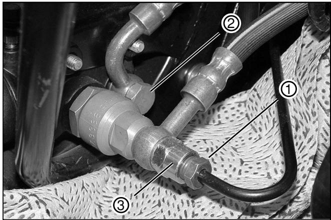
Replacing the pressure divider valve Removal
Should the braking action between the front left and rear calipers by unevenly distributed (e.g. with the same surface and adhesive force on both wheels the rear brake jams while the front brake is not applied or vice versa, or the brakes work in a completely different manner, or the divider valve does not work properly), follow these steps:
- Empty the combined brake circuit as previously described.
- Remove the front countershield as described in Chapter 8-Bodywork.
- Unscrew rear caliper connection 1 (see figure).
Note: Place a rag under the divider valve to prevent brake fluid from soiling the brake pads or other components.
- Remove front brake caliper connection 2.
- Remove connection 3, conveying the fluid from the pump to the valve.
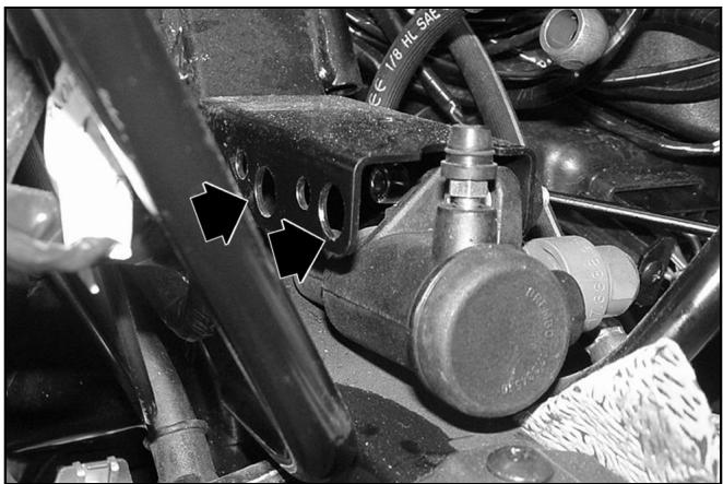
- Remove the two cheese-headed socket screws fixing the valve to the frame in the two holes shown in the figure.
- Remove the valve and replace it with a new one.
07_016
07 017
Fitting
Follow the reverse procedure to the removal.
Note: Fit new copper gaskets on the connections.
- Tighten the screws fixing the valve to the frame and, above all, the connections on the brake lines with the prescribed torque.
- Fill and bleed the brake circuit as previously described.
Tightening torques:
Oil pump - Integral braking device tube connection: 16 - 20 N·m
Front brake caliper - Integral braking device connection: 20 - 25 N·m
Rear brake caliper - Integral braking device connection: 20 - 25 N·m
TABLE OF CONTENTS
: Perform all operations with great care. Plastics are easily damaged.
: Avoid cleaning painted plastics with solvents containing petrol and its derivatives.

LUBRICATE WITH OIL

LUBRICATE WITH GREASE

APPLY PRODUCT

CLEAN CAREFULLY

WARNING - HANDLE WITH CARE

ALWAYS REPLACE
Front central cover
- Lift the rearview mirror covers.
- Unscrew the five fixing screws shown in the figure.
- Remove the front central cover with the weather strip.
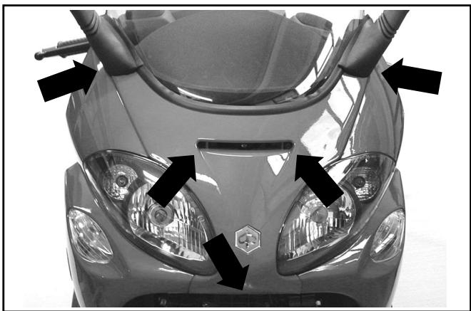
08_001
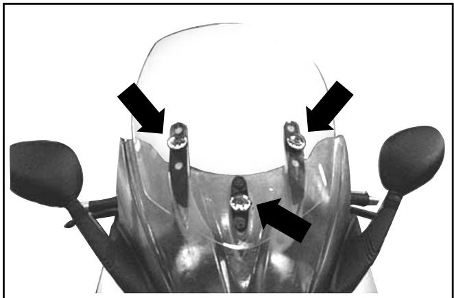
Lower guard - Windscreen
- Remove the rearview mirrors;
- Unloose the 3 fixing screws shown in the figure and relevant spacers;
- Remove the upper windscreen;
- Unloose the 4 fixing screws with washers, located under the rearview mirrors and under the front central cover;
- Remove the lower guard and relevant weather strip.
Note: When refitting, take care to properly reinsert the weather strips into their seats.
08_002A
Front lamp cluster
- Remove the three fixing screws.
- Detach the electrical connectors.
- Remove the front lamp cluster by pulling it forward.
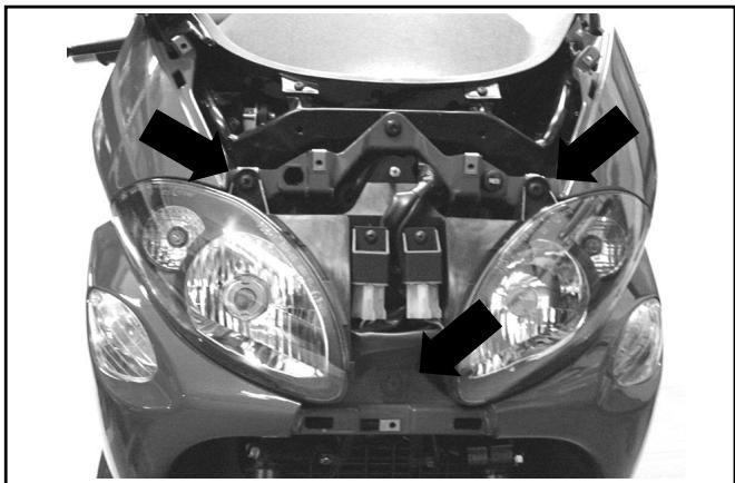
08_003
Front shield
- Remove the two front screws.
- Remove the two screws behind the wheel.
- Unscrew the remaining six fixing screws.
- Detach the electrical connectors.
- Remove the front shield with the turn indicators.
08_004
Digital instrument panel support
- Remove the three fixing screws.
- Detach the electrical connectors.
- Remove the support with the digital instrument panel.
- Pay special attention to the electrical connectors.
08_005
Front handlebar cover
- Loosen the two screws fixing the radio-interphone unit.
- Detach the electrical connectors.
- Remove the radio-interphone.
- Remove the two handlebar cover lower screws (one on each side).
08_006
- Remove the brake fluid pump cover on the right side.
- Remove the front handlebar cover.
08_007
Rear handlebar cover
- Remove the three fixing screws.
- Detach the electrical connectors.
- Remove the rear handlebar cover.
08_008
TABLE OF CONTENTS

| 1 ENGINE | Op. | Code | Description | Time |
| 1-2-3
1-2-3
1-2-3
1-2-3
1-2-3
1-2-3
1-2-3
1-2-3
1-2-3
1-2-3
1-2-3
1-2-3
1-2-3
1-2-3
1-2-3
1-2-3
1-2-3
1-2 | 1
2
3 | 001001
001127
003057 | Engine from frame - Removal and reinstatement
Engine - Complete overhaul
Engine anchorage - Tightening of nuts | 160'
450'
20' |
| 2 CRANKCASE | Op. | Code | Description | Time |
| 1
2
3 | 1
2
3 | 001133
001153
001100 | Crankcase - Replacement
Crankcase half gasket - Replacement
Oil seal clutch side - Replacement | 410'
280'
60' |
| 3 CRANKSHAFT | Op. | Code | Description | Time |
| 1
2 | 1
2 | 001117
001098 | Crankshaft - Replacement
Countershaft - Replacement | 310'
290' |
| 4 CYLINDER - PISTON - PISTON PIN ASSEMBLY | Op. | Code | Description | Time |
| 1
2
3 | 1
2
3 | 001002
001154
001129 | Cylinder-piston - Replacement
Piston-piston rings-piston pin assembly - Overhaul
Chain stretcher - Overhaul and replacement | 250'
240'
45' |
| 5 CYLINDER HEAD | Op. | Code | Description | Time |
| 6 Rocker ARM SUPPORT ASSEMBLY | 1 | 001126 | Cylinder head - Replacement | 250' |
| 2 | 001045 | Valves - Replacement | 240' |
| 3 | 001049 | Valves - Adjustment | 75' |
| 4 | 001056 | Cylinder head gasket - Replacement | 210' |
| 5 | 007023 | Union tee head outlet - Replacement | 95' |
| 6 | 005081 | Temperature sensor - Replacement | 80' |
| | | |
| 7 CYLINDER HEAD COVER | Op. | Code | Description | Time |
| 8 FLYWHEEL COVER | 1 | 001089 | Cylinder head cover - Replacement | 70' |
| 2 | 001093 | Spark plug - Replacement | 15' |
| 3 | 001088 | Cylinder head cover gasket - Replacement | 70' |
| | | |
| 1 | 001087 | Flywheel cover - Replacement | 105' |
| 2 | 001113 | Water pump - Replacement | 60' |
| 3 | 001123 | Oil filter - Replacement | 15' |
| 4 | 001124 | By-pass - Replacement | 100' |
| 5 | 001057 | Thermostat - Replacement | 55' |
| 6 | 001062 | Water pump control shaft - Replacement | 85' |
| 7 | 001150 | Flywheel cover gasket - Replacement | 100' |
| 8 | 001160 | Oil minimum pressure sensor - Replacement | 20' |
| 9 | 007011 | By pass sleeve-Thermostat-Drain valve - Replacement | 70' |
| 10 | 007019 | Water pump connection pipe-Return pipe - Replacement | 70' |
| 11 | 007012 | Drain valve - Coolant outlet pipe - Replacement | 70' |
| 9 DRIVEN PULLEY AND CLUTCH | Op. | Code | Description | Time |
| 3-4
1-2
6 | 1 | 001022 | Clutch - Replacement | 60' |
| 2 | 003072 | Clutch assembly - Wear check | 50' |
| 3 | 001012 | Driven pulley - Overhaul | 75' |
| 4 | 001110 | Driven pulley - Replacement | 60' |
| 5 | 001155 | Clutch bell housing - Replacement | 50' |
| 6 | 001167 | Driven pulley shaft support - Overhaul / Replacement | 60' |
| 10 OIL PUMP | Op. | Code | Description | Time |
| 4
3
1-2 | 1 | 001112 | Oil pump - Replacement | 270' |
| 2 | 001042 | Oil pump - Overhaul | 280' |
| 3 | 001051 | Timing chain/belt - Replacement | 220' |
| 4 | 001125 | Chain guide shoes - Replacement | 225' |
| 11 REDUCTION GEARING ASSEMBLY | Op. | Code | Description | Time |
| 1
2
3 | 1 | 001010 | Reduction gearing - Overhaul | 75' |
| 2 | 001156 | Reduction gearing cover - Replacement | 75' |
| 3 | 003065 | Gear box oil - Renewal | 15' |
| 12 DRIVING PULLEY | Op. | Code | Description | Time |
| 4
3
2 | 1 | 001086 | Driving half pulley - Replacement | 50' |
| 2 | 001011 | Drive belt - Replacement | 65' |
| 3 | 001006 | Driving pulley - Overhaul | 55' |
| 4 | 001141 | Belt antiflapping roller - Replacement | 45' |
| 5 | 001066 | Driving pulley - Disassembly and reassembly | 55' |
| 13 TRANSMISSION COVER | Op. | Code | Description | Time |
| 1 | 001096 | Transmission crankcase cover - Replacement | 35' |
| 2 | 008002 | Mechanical transmission cover - Replacement | 30' |
| 14 STARTER MOTOR | Op. | Code | Description | Time |
| 1 | 001020 | Starter motor - Replacement | 40' |
| 2 | 001017 | Starter pinion - Replacement | 90' |
| 3 | 003064 | Engine oil - Replacement | 20' |
| 15 FLYWHEEL MAGNETO | Op. | Code | Description | Time |
| 1 | 001058 | Flywheel - Replacement | 100' |
| 2 | 001067 | Stator - Removal and reinstallation | 95' |
| 3 | 001104 | Starting free wheel - Replacement | 100' |
| 4 | 001151 | Starting driven gear - Replacement | 100' |
| 16 THROTTLE BODY | Op. | Code | Description | Time |
| 1 | 001013 | Intake manifold - Replacement | 75' |
| 2 | 001047 | Injector - Replacement | 70' |
| 3 | 001166 | Throttle body - Replacement | 70' |
| 17 AIR CLEANER | Op. | Code | Description | Time |
| 1 1 2 | 1 | 001015 | Air filter box - Replacement | 40' |
| 2 | 001014 | Air filter - Replacement/Cleaning | 20' |
| 18 SILENCER | Op. | Code | Description | Time |
| 1 1 3 2 | 1 | 001009 | Silencer - Replacement | 10' |
| 2 | 001092 | Exhaust manifold - Replacement | 20' |
| 3 | 001095 | Silencer guard - Replacement | 5' |
| 4 | 001136 | Exhaust emissions - Adjustment | 30' |
| 19 TANK | Op. | Code | Description | Time |
| 2 1 3 | 1 | 004073 | Fuel pump - Replacement | 20' |
| 2 | 004005 | Fuel tank - Replacement | 65' |
| 3 | 004137 | Fuel pump tube - Replacement | 70' |
| 20 FRAME BODY | Op. | Code | Description | Time |
| 3 1 | 1 | 004001 | Frame - Replacement | 480' |
| 2 | 004146 | Front frame - Replacement | 50' |
| 3 | 004116 | Rear frame - Replacement | 45' |
| 21 SWINGARM | Op. | Code | Description | Time |
| 1 | 001072 | Engine-frame connection swing arm - Replacement | 65' |
| 2 | 003082 | Damper arm - Replacement | 65' |
| 22 CENTRAL STAND/ELECTROHYDRAULIC | Op. | Code | Description | Time |
| 1 | 004004 | Stand - Replacement | 65' |
| | | | |
| 23 SIDESTAND | Op. | Code | Description | Time |
| 1 | 004102 | Side stand - Replacement | 20' |
| 2 | 005079 | Stand switch - Replacement | 40' |
| | | | |
| 24 FRONT SHIELD | Op. | Code | Description | Time |
| 1 | 004064 | Front shield, front section - Replacement | 35' |
| 2 | 006012 | Front shield - Painting | 30' |
| 3 | 004149 | Front shield central cover - Replacement | 10' |
| 4 | 006006 | Steering head tube cover - Painting | 30' |
| 5 | 005085 | Reset button - Replacement | 10' |
| | | | |
| 25 WINDSCREEN | Op. | Code | Description | Time |
| 1 | 004028 | Windscreen glass - Replacement | 15' |
| 2 | 004066 | One rearview mirror - Replacement | 10' |
| 26 REAR SHIELD | Op. | Code | Description | Time |
| 1 | 004065 | Front shield, rear section - Removal and refitting | 50' |
| 2 | 004081 | Glove compartment door - Replacement | 50' |
| 3 | 002082 | Fuel tank door opening cable - Replacement | 50' |
| 4 | 004156 | Glove compartment door and/or support - Replacement | 40' |
| 27 FOOTBOARD - FUEL TANK DOOR | Op. | Code | Description | Time |
| 1 | 004135 | Fuel tank door - Replacement | 15' |
| 2 | 004011 | Frame central cover - Replacement | 20' |
| 3 | 004157 | Fuel tank door catch - Replacement | 15' |
| 28 EXPANSION TANK | Op. | Code | Description | Time |
| 1 | 007001 | Expansion tank - Replacement | 40' |
| 2 | 007013 | Expansion tank connection pipe, radiator - Replacement | 45' |
| 3 | 001052 | Coolant renewal and air bleeding - Replacement | 60' |
| 29 RADIATOR | Op. | Code | Description | Time |
| 1 2 3 4 | 007002
007016
007003
007022 | Radiator - Replacement
Fan complete with support - Replacement
Coolant delivery and return pipe - Replace.
Coolant return pipe - Replacement | 110'
100'
80'
60' | |
| 30 UNDERSADDLE COMPARTMENT | Op. | Code | Description | Time |
| 1 2 3 4
6 1
5 1
1 | 005033
005026
005027
004142
004016
002083 | Glove compartment lamp switch - Repl.
Helmet compartment lamp - Replacement
Helmet compartment lamp support - Repl.
Electrical socket - Replacement
Helmet compartment - Removal and refitting
Saddle opening cable - Replacement | 50'
5'
5'
5'
45'
70' | |
| 31 MATS AND COVERS | Op. | Code | Description | Time |
| 1 3 4-6
1 5-7
9-11 2 10 | 004075
004076
004068
004012
004129
006005
006008
004059
004079
004053
004015 | 1 front mat - Replacement
One rear mat - Replacement
One grab handle - Replacement
2 Rear body sides - Removal and refitting
Rear side panel - Replacement
Two side covers - Painting
Rear side fairing - Painting
Spark plug inspection door - Replacements
Footrest (1) - Replacement
Spoiler - Replacement
Footboards - Replacement | 10'
40'
10'
30'
20'
50'
40'
5'
35'
50'
50' | |
| 32 FRONT MUDGUARDS | Op. | Code | Description | Time |
| 1 2 1-2 | 004002
006003 | Front mudguard - Replacement
Front mudguard - Painting | 10'
30' | |
| 33 SADDLE | Op. | Code | Description | Time |
| 5 4 1 2 | 1 | 004003 | Saddle - Replacement | 10' |
| 2 | 004144 | Bag - Replacement | 10' |
| 3 | 004150 | Saddle damper - Replacement | 5' |
| 4 | 004067 | Rider's backrest - Replacement | 10' |
| 5 | 004054 | Saddle catch - Replacement | 10' |
| 34 STEERING THRUST RINGS | Op. | Code | Description | Time |
| 1-2-3 | 1 | 004119 | Steering upper thrust ring/bearing - Replace. | 60' |
| 2 | 003002 | Steering thrust rings - Replacement | 80' |
| 3 | 003073 | Steering play - Adjustment | 30' |
| 35 FRONT FORK | Op. | Code | Description | Time |
| 1 2 3 | 1 | 003051 | Fork assembly - Replacement | 60' |
| 2 | 003079 | Fork rod - Replacement | 30' |
| 3 | 003048 | Fork oil seal - Replacement | 40' |
| 36 REAR SHOCK ABSORBER | Op. | Code | Description | Time |
| 1 1 3 2 | 1 | 003007 | Rear shock absorber - Removal and refitting | 20' |
| 37 INSTRUMENT PANEL | Op. | Code | Description | Time |
| 38 HANDLEBAR COVERS | 1 | 005014 | Speedometer - Replacement | 35' |
| 2 | 005078 | Speedometer glass - Replacement | 40' |
| 3 | 005082 | Instrument panel wiring - Replacement | 35' |
| 4 | 005083 | Trip computer - Replacement | 10' |
| | | |
| 1 | 004151 | Instrument panel support - Replacement | 30' |
| 2 | 004018 | Handlebar front section - Replacement | 15' |
| 3 | 004019 | Handlebar rear section - Replacement | 20' |
| 4 | 006013 | Handlebar front section - Painting | 30' |
| 5 | 006014 | Rear handlebar protection - Painting | 30' |
| 6 | 004152 | Trip computer cover - Replacement | 10' |
| | | |
| 39 HANDLEBAR COMPONENTS | Op. | Code | Description | Time |
| 1 3 2 5 9 10 6-8 | 1 | 002060 | Throttle control assembly - Replacement | 20' |
| 2 | 002037 | Brake or clutch lever - Removal | 20' |
| 3 | 002071 | Left handgrip - Replacement | 10' |
| 4 | 002024 | Brake pump - Removal and reinstallation | 40' |
| 5 | 003001 | Handlebar - Removal and refitting | 40' |
| 6 | 002063 | Throttle control cable assembly - Replacement | 70' |
| 7 | 002059 | Throttle twist grip - Replacement | 10' |
| 8 | 003061 | Throttle control cable - Adjustment | 15' |
| 9 | 002088 | All-wheel brake pump - Replacement | 50' |
| 10 | 005017 | Stoplight switches - Replacement | 20' |
| 40 BRAKE LINES | Op. | Code | Description | Time |
| 1 6 2 3 4 5 7 8 | 1 | 002021 | Front brake line - Removal and refitting | 65' |
| 2 | 002084 | All-wheel brake pump tube device - Replacement | 60' |
| 3 | 002085 | Front caliper all-wheel braking device tube - Replacement | 60' |
| 4 | 002087 | All-wheel braking rear rigid tube - Replacement | 80' |
| 5 | 002090 | All-wheel brake fluid - Renewal and system bleeding | 40' |
| 6 | 002047 | Front brake oil and system draining - Replacement | 25' |
| 7 | 002089 | Integral braking device - Replacement | 60' |
| 41 BRAKE CALIPER | Op. | Code | Description | Time |
| 1-2-5-6 3-4
1-2-5-6
REVVISION
Rear BRAKE CALIPER | 1 | 002007 | Front brake shoes/pads - Replacement | 10' |
| 2 | 003070 | Front brake pads/shoes - Wear check | 5' |
| 3 | 002039 | Brake caliper - Removal and refitting | 20' |
| 4 | 002048 | Front brake caliper - Replacement | 45' |
| 5 | 002002 | Rear brake pads - Replacement | 45' |
| 6 | 003071 | Rear brake pads/hook - Wear check | 40' |
| 42 HEADLIGHT | Op. | Code | Description | Time |
| 1-2-5-6 3
1-2-5-6
REVVISION
Rear BRAKE CALIPER | 1 | 005002 | Headlight - Replacement | 15' |
| 2 | 005008 | Headlight bulbs - Wear check | 15' |
| 3 | 005044 | Headlight wiring harness - Replacement | 15' |
| 4 | 005067 | Front turn indicator bulb - Replacement | 10' |
| 5 | 005012 | Front turn indicators - Replacement | 30' |
| 6 | 005091 | Turn indicators glass - Replacement | 5' |
| 43 REAR LIGHT | Op. | Code | Description | Time |
| 1-2-5-6 3
1-2-5-6
REVVISION
Rear BRAKE LIGHT | 1 | 005090 | Stoplight bulbs - Replacement | 15' |
| 2 | 004141 | Reflector - Replacement | 15' |
| 3 | 005005 | Rear light - Replacement | 15' |
| 4 | 005066 | Rear light bulbs - Replacement | 15' |
| 5 | 005031 | Number-plate light bulb - Replacement | 5' |
| 6 | 005032 | Number-plate light lens - Replacement | 15' |
| 7 | 005030 | Rear light wiring harness - Replacement | 15' |
| 44 REAR COVERS | Op. | Code | Description | Time |
| 1-2-5-6 3
1-2-5-6
REVVISION
Rear BRAKE COVERS | 1 | 004057 | Tail lamp lower cover - Replacement | 15' |
| 2 | 004009 | Rear mudguard - Replacement | 20' |
| 3 | 005048 | Number plate holder - Replacement | 5' |
| 4 | 005046 | Battery cover - Replacement | 10' |
| 45 ELECTRICAL DEVICES | Op. | Code | Description | Time |
| 7 6 5 7
1 8 3 4 | 1 | 005040 | Horn button - Replacement | 20' |
| 2 | 005041 | Starting device button - Replacement | 20' |
| 3 | 005084 | Hazard warning light button - Replacement | 20' |
| 4 | 005095 | Electrical stand push button - Replacement | 20' |
| 5 | 005077 | Emergency stop switch - Replacement | 10' |
| 6 | 005039 | Lights selector switch - Replacement | 10' |
| 7 | 005006 | Lights or turn indicator switch - Replacement | 10' |
| 8 | 005003 | Horn - Replacement | 50' |
| 46 BATTERY AND HV COIL | Op. | Code | Description | Time |
| 2 6 3
1 5 4 | 1 | 001069 | HV coil - Replacement | 35' |
| 2 | 005007 | Battery - Replacement | 20' |
| 3 | 005011 | Starting relay switch - Replacement | 20' |
| 4 | 005097 | Electrical central stand electromagnetic switch - Replacement | 20' |
| 5 | 001094 | Spark plug cap - Replacement | 15' |
| 6 | 005024 | Battery fuse - Replacement | 10' |
| 47 FUEL INJECTION CONTROL UNIT | Op. | Code | Description | Time |
| 1 3 2
1 5 4 | 1 | 005035 | Headlight relay switch - Replacement | 10' |
| 2 | 005073 | Decoder - Replacement | 40' |
| 3 | 001023 | Electronic control unit - Replacement | 40' |
| 48 VOLTAGE REGULATOR ASSEMBLY | Op. | Code | Description | Time |
| 3 4
1 2
1 | 1 | 005009 | Voltage regulator - Replacement | 30' |
| 2 | 005098 | Stand control unit - Replacement | 25' |
| 3 | 005088 | Hazard warning light relay switch - Replacement | 25' |
| 4 | 005096 | Injection components electromagnetic switch - Replacement | 25' |
| 49 RADIO - INTERCOM | Op. | Code | Description | Time |
| 3 1 2 | 1 | 005092 | Radio / intercom control unit - Replacement | 45' |
| 2 | 005093 | Radio / Intercom cables - Replacement | 60' |
| 3 | 005094 | Radio / Intercom display - Replacement | 15' |
| 50 WIRING (WIRING HARNESS) | Op. | Code | Description | Time |
| 2 1 2 | 1 | 005001 | Electrical equipment - Removal and reinstallation | 140' |
| 2 | 005025 | Battery fuse holder - Replacement | 10' |
| 51 LOCKS | Op. | Code | Description | Time |
| 1 1-2 | 1 | 005016 | Ignition switch - Replacement | 25' |
| 2 | 004010 | Security lock - Replacement | 50' |
| 52 FRONT WHEEL | Op. | Code | Description | Time |
| 7 6 1-4 2-5 3 | 1 | 003037 | Front wheel rim - Removal and refitting | 30' |
| 2 | 003047 | Front tyre - Replacement | 20' |
| 3 | 004123 | Front wheel - Replacement | 20' |
| 4 | 006018 | Wheel rim - Painting | 35' |
| 5 | 003063 | Tyre pressure - Check | 5' |
| 6 | 003040 | Front wheel bearings - Replacement | 40' |
| 7 | 002041 | Front brake disc - Replacement | 20' |
| 8 | 005089 | Speed sensor - Replacement | 15' |
| 53 REAR WHEEL | Op. | Code | Description | Time |
| 6-7 2-5 1-4 9 8 3 | 1 | 001071 | Rear wheel rim - Removal and refitting | 45' |
| 2 | 004126 | Rear tyre - Replacement | 45' |
| 3 | 001016 | Rear wheel - Replacement | 35' |
| 4 | 006018 | Wheel rim - Painting | 35' |
| 5 | 003063 | Tyre pressure - Check | 5' |
| 6 | 003014 | Rear suspension arm - Replacement | 20' |
| 7 | 003077 | Silencer/rear shock absorber support arm - Overhaul | 25' |
| 8 | 002070 | Rear brake disc - Replacement | 40' |
| 9 | 002028 | Rear wheel hub - Replacement | 40' |
| | | | |
| | | | |
| | | | |
| | | | |
| | | | |
| | | | |