USER MANUAL X8 PIAGGIO
PIAGGIO WOULD LIKE TO THANK YOU
for choosing one of its products. We have prepared this booklet to help you to get the very best from your scooter. Please read it carefully before riding the scooter for the first time. It contains information, tips and precautions for using your scooter. It also describes features, details and devices to assure you that you have made the right choice. We believe that if you follow our suggestions, you will soon get to know your new vehicle and it will serve you well for a long time to come. This booklet forms an integral part of the scooter; should the scooter be sold, it must be transferred to the new owner.
X8 400 i.e.

PIAGGIO
The instructions given in this manual are intended to provide a clear, simple guide to using your scooter; this booklet also details routine maintenance procedures and regular checks that should be carried out on the vehicle at an authorised Dealer or Service Centre. The booklet also contains instructions for simple repairs. Any operations not specifically described in this manual require the use of special tools and/or particular technical knowledge: to carry out these operations refer to any authorised Dealer of Service Centres.

Personal safety
Failure to completely observe these instructions will result in serious risk of personal injury.

Safeguarding the environment
Sections marked with this symbol indicate the correct use of the vehicle to prevent damaging the environment.

Vehicle intactness
The incomplete or non-observance of these regulations leads to the risk of serious damage to the vehicle and sometimes even the invalidity of the guarantee.
The signs that you see on this page are very important. They are used to highlight those parts of the booklet that should be read with particular care. As you can see, each sign consists of a different graphic symbol, making it quick and easy to locate the various topics.
INDEX
VEHICLE 7
8
Analogue instrument panel. 9
Clock. 10
Setting the hour/minutes function. 10
Key switch. 10
Locking the steering wheel. 11
Releasing the steering wheel 11
Switch direction indicators 11
Horn button. 12
Light switch. 12
Start-up button. 13
Engine stop button. 13
The immobilizer system 13
Keys. 14
Immobilizerdevice enabled indicator led. 15
Operation 15
Programming the immobilizer system 16
Saddle opening remote control. 18
Remote control programming. 18
Power supply socket. 20
The saddle. 20
Opening the saddle to access the helmet compartment by
remote control. 21
Opening the saddle 22
Opening the saddle to access the helmet compartment in an emergency. 22
Identification 23
Rear top box opening button. 24
USE 27
Checks 28
Refuelling. 28
Tyre pressure. 30
Shock absorbers adjustment. 31
Running in. 32
Starting up the engine 33
Precautions 35
Difficult start up. 35
Stopping the engine 36
Stand. 37
Automatic transmission 38
Safe driving. 39
MAINTENANCE 43
Engine oil level. 44
Engine oil level check. 44
Engine oil top-up. 45
Warning light (insufficient oil pressure) 45
Engine oil change 46
Hub oil level 47
Tyres. 49
Spark plug dismantlement 51
Removing the air filter. 52
Air filter cleaning. 52
Cooling fluid level. 53
Checking the brake oil level. 55
Braking system fluid top up. 56
Battery. 57
Use of a new battery. 57
Checking the electrolyte level. 58
Long periods of inactivity 59
Fuses 59
Front light group. 66
Headlight adjustment 67
Front direction indicators 67
Rear optical unit 68
Rear turn indicators. 69
Number plate light. 69
Helmet compartment lighting bulb. 70
Rear-view mirrors. 71
Front and rear disc brake. 71
Puncture. 72
Periods of inactivity. 73
Cleaning the vehicle. 74
TECHNICAL DATA. 79
Kit equipment. 83
SPARE PARTS AND ACCESSORIES 85
Warnings. 86
PROGRAMMED MAINTENANCE 89
Scheduled maintenance table. 90
X8 400 i.e.

PIAGGIO

Chap. 01 Vehicle
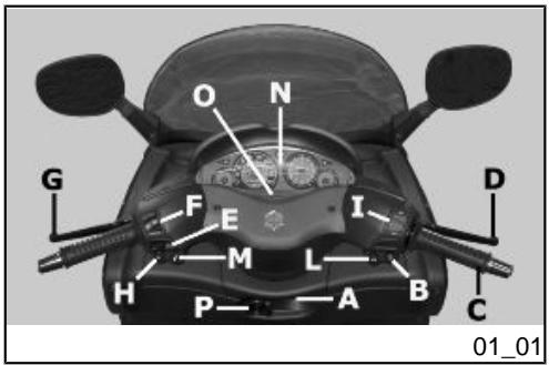
[ \text{ Dashboard(01_01, 01_02)} ]
A = Ignition key-switch
B = Starter button
C = Throttle control
D = Front brake lever
E = Turn indicator switch
F = Headlight switch
G = Rear brake lever
H = Horn button
I = Engine cut-off switch
L = Boot opening switch
M = Saddle opening button
N = Instrument panel unit
O = Indicator unit
P = Bag hook
![PIAGGIO X8 - [ \text{ Dashboard(01_01, 01_02)} ] - 1](/content/2019/10/11122/images/e991d6fdc024071fc663b4a74a0eb229c175de73efb5e6e859b45c05f2975db5.jpg)
Analogue instrument panel (01_03)
A = Twin scale speedometer (km/h and mph)
B = Fuel gauge
C = LED immobilizer / anti-theft device
D = Coolant temperature gauge
E = Right turn signal warning light
E = Left turn signal warning light
H = Low fuel warning light
I = Lights ON warning light
L = High-beam warning light
M = Low oil pressure warning light
N = Helmet compartment light ON warning light
O = Engine control telltale light and injection system failure warning light
P = Analogue clock
Q = Total odometer
R = Trip odometer
S = Trip odometer reset button
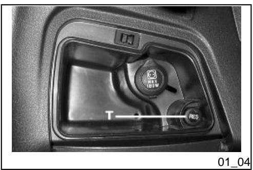
Clock (01_04)
The clock, powered directly by the vehicle's battery, may be set by pressing the «T» button located inside the LHS glove-box on the knee-guard panel.
Pressing the button for less than one second will add one minute to the displayed time; Keep the «T» button pressed to rapidly increase the time.
Setting the hour/minutes function
Pressing the "RES" key increases the minutes of the indicated time one by one. Hold the "RES" key down to increase the numbers faster.
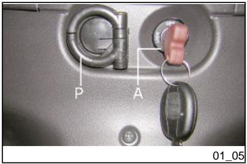
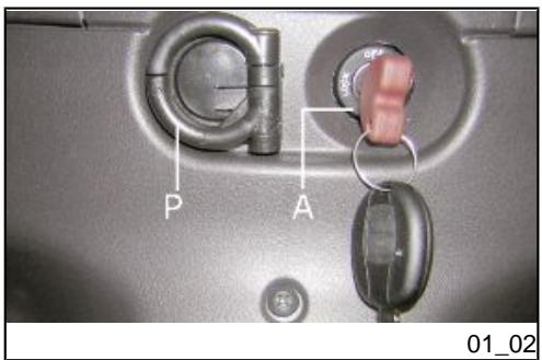
Key switch (01_05)
LOCK = Ignition disabled, extractable key, mechanical antitheft device enabled. OFF = Ignition disabled, extractable key, mechanical antitheft device disabled. ON = Ready to start, non-extractable key, mechanical antitheft device disabled.
Locking the steering wheel
Turn the handlebar to the left as far as it will go, turn the key to position "LOCK" and remove the key.
Releasing the steering wheel
Reinsert the key and turn it to «OFF».
CAUTION

DO NOT TURN THE KEY TO «LOCK» OR «OFF» WHILE RIDING.
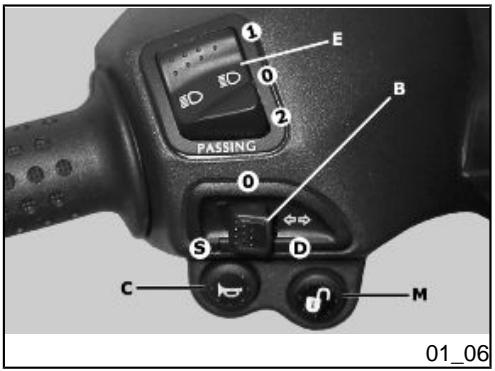
Switch direction indicators (01_06)
Lever towards "S" = Left turn indicator is switched on;
Lever towards "D" = Right turn indicator is switched on;
The lever returns automatically to position "0" and the turn indicator "B" remains on; press the lever to turn them off.
Push the «C» button to sound the horn.
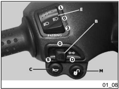
Light switch (01_08)
0 = Low-beam light
1 = High beam light
2 = Passing (flashing)

To start the engine, press the starter button "G" while pulling either of the two brake levers.
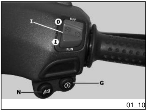
Functioning of the engine cut-off switch "I":
$$
\begin{array}{l} 0 = O F F \ 1 = R U N \ \end{array}
$$
The immobilizer system
In order to enhance theft protection, the scooter is equipped with a «PIAGGIO IMMOBILIZER » electronic engine locking device that is activated automatically when the starter key is removed. Upon start-up, the «PIAGGIO IMMOBILIZER» system
checks the starter key, and only if this key is recognised will the immobilizer system allow the scooter to be started.
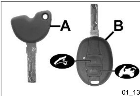
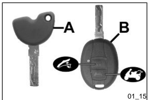
Keys (01_11, 01_12, 01_13)
Two types of keys come with the vehicle.
The red-handgrip key "A" is the "MASTER" key.
Only a single copy of this key is supplied, which is necessary to program all your other keys and for your dealer to perform some maintenance operations. For this reason it is advised that it be used only in exceptional circumstances.
The black key "B" (single copy supplied) is used for normal operations such as:
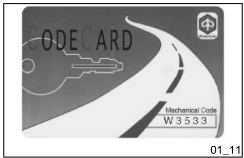
Together with the two keys, you will be given a CODE CARD bearing the same code imprinted onto the two keys.
WARNING

LOSING THE RED KEY PREVENTS ANY REPAIRS OF THE 'PIAGGIO IMMOBILIZER' SYSTEM AND THE ENGINE CONTROL UNIT.
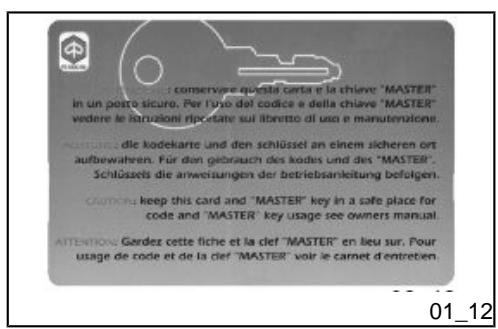
WARNING

KEEP THE 'CODE CARD' AND THE RED HANDGRIP KEY IN A SAFE PLACE (NOT ON YOUR VEHICLE).
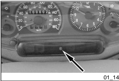
Immobilizerdevice enabled indicator led (01_14)
Activation of the "PIAGGIO IMMOBILIZER" system is signalled by a flashing "C" indicator. In order to reduce battery discharge, the indicator LED turns off automatically after 48 hours of uninterrupted functioning. Should the signal led system break down in its flashing function, give information about the type of problem to an Authorised Piaggio-Gilera Service Centre.
Operation
Every time the starter key is removed in the "OFF" or "LOCK" position, the safety system activates the immobilizer system. Turning the key to "ON" disables the engine lock, provided that the safety system recognises the code transmitted by the key. If the code is not recognised, turn the key first to "OFF" and then to "ON"; if the lock cannot be disabled, try with the other key supplied (red-coloured). If the engine cannot be started, contact an Authorised Piaggio Service Centre, which is provided with the electronic equipment required to detect and repair the system.
When additional keys are required, please note that data storage (up to 7 keys max.) must be done on all keys, both new ones and existing ones.
Take the red-handgrip key and all the black keys supplied to an Authorised Piaggio Service Centre.
The codes of keys not submitted for the new storage procedure are deleted from the memory. Any lost keys will therefore not be enabled to start the engine.
WARNING

EACH KEY HAS ITS OWN AND UNIQUE CODE, WHICH MUST BE STORED BY THE SYSTEM CONTROL UNIT.
VIOLENT SHOCKS MAY AFFECT THE ELECTRONIC COMPONENTS OF THE KEY.
IF OWNERSHIP OF THE VEHICLE IS TRANSFERRED, THE RED-HANDGRIP KEY (AS WELL AS THE OTHER KEYS) AND THE "CODE CARD" MUST ALSO BE TRANSFERRED TO THE NEW OWNER.
Programming the immobilizer system
Below is described the procedure to follow for programming the PIAGGIO IMMOBILIZER system and/or for storing other key codes. The programming procedure should be carried out with the engine stop switch set to «RUN».
Procedure start - red key
Insert the red-handgrip key in the switch key (in "OFF" position) and turn it to "ON". After 1 - 3 seconds, turn the key to "OFF" again and pull it out.
After pulling out the red key, insert the black key within 10 seconds and promptly turn it to «ON». After 1-3 seconds, turn the key to "OFF" again and pull it out. In this way, a maximum of 7 black keys can be programmed by repeating the above procedure keeping the indicated times.
Final step - red key
After pulling out the last black key, insert the red key again and turn it to "ON" (this operation should be performed within 10 seconds of pulling out the previous key). Leave it in this position for 1 to 3 seconds and return it to the «OFF» position.
Proper programming check
Insert the red key disabling the transponder (i.e., tilt the key cap by 90^ ) and turn the key to "ON". Perform the engine start-up operation. Ensure that the engine does not start. Insert the black key and repeat the start-up operation. Check that engine starts.
WARNING
SHOULD THE ENGINE START WITH THE RED KEY (WITH TRANSPONDER OFF), OR IN THE EVENT OF WRONG OPERATION DURING PROGRAMMING, REPEAT THE PROCEDURE FROM THE BEGINNING.
Saddle opening remote control (01_15, 01_16)
The vehicle is equipped with a key with remote control to open the saddle and the back compartment cover from the distance. This remote control is supplied together with the «MASTER» key and it has been programmed to control the opening device control unit at the manufacturing stage. A maximum of 7 keys operated by remote control can be programmed (see «remote control programming» section). The remote control for the black key is powered by inner batteries that get discharged after extended used; If the green LED on the handgrip turns on when the button is pressed, the remote control is working properly.
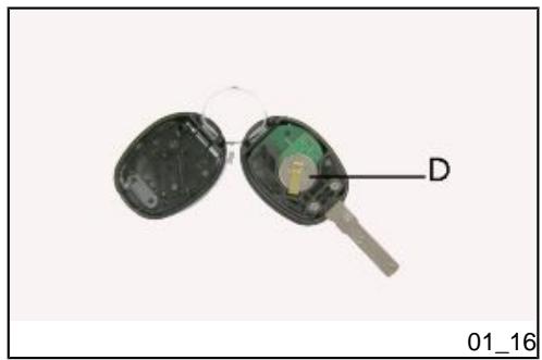
You may need to replace the batteries inside the key if the remote control fails or if its range of operation is reduced.
In order to carry out this operation, separate the two halves of the remote control by inserting an edge or the thin tip of a plain slot screwdriver on the external groove and slide it all around said groove.
Go to the printed circuit and remove the two batteries from the contact terminal; replace the two batteries «D», paying attention to reassemble them with the poles facing the correct sense and with new CR1616 batteries, then reassemble the handgrip.
To open the saddle without the remote control, follow the procedure described in the «Saddle» or «Opening saddle with remote control» section
Remote control programming
Follow these steps to program the remote controls:
- Insert the remote control key to be programmed in the steering lock key block.
- Turn the key to «ON», press the button on the remote control, release the button, turn the key back to «OFF» from the «ON» position, all within 4 seconds.
3 Wait 1 to 8 seconds.
- Repeat steps 2 and 3 for 4 times without removing the key.
The control unit confirms the programming has been successfully executed by opening the saddle.
WARNING

TO STORE THE OTHER REMOTE CONTROLS TO MEMORY, (MAXIMUM 8), YOU NEED TO REPEAT THE WHOLE PROCEDURE AGAIN. FAILURE TO CARRY OUT THESE OPERATIONS WITHIN THE INDICATED TIMES WILL RESULT IN THE AUTOMATIC CANCELLATION OF THE PROCESS FOR PROGRAMMING THE REMOTE-CONTROLLED KEYS.
WARNING

AVOID PRESSING THE REMOTE CONTROL BUTTON MORE THAN ONCE WHEN FAR AWAY FROM THE SCOOTER. THE SYNCHRONISM BETWEEN THE REMOTE CONTROL AND THE RECEIVER CAN BE IMPAIRED. SHOULD THIS BE THE CASE, REPEAT THE PROGRAMMING PROCEDURE. DO NOT KEEP THE REMOTE CONTROL IN PLACES WITH TEMPERATURES EXCEEDING 60^ C THE BATTERY WILL RUN DOWN TOO QUICKLY.
WARNING

TO AVOID BATTERY DISCHARGE, THE SADDLE OPENING REMOTE CONTROL RADIO RECEIVER DEACTIVATES 7 DAYS AFTER THE LAST TIME THE VEHICLE WAS SHUT OFF.
JUST TURN THE KEY TO «ON» TO REACTIVATE THE RECEIVER.
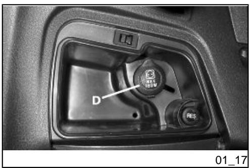
Power supply socket (01_17)
The scooter is equipped with a 12V socket, "D", inside the LHS glove compartment. This may be used to power electrical devices with a maximum power below 180W (i.e. mobile phones, flashlights, etc.).
CAUTION

PROLONGED USE OF THE PLUG SOCKET MAY RESULT IN PARTIAL DISCHARGE OF THE BATTERY
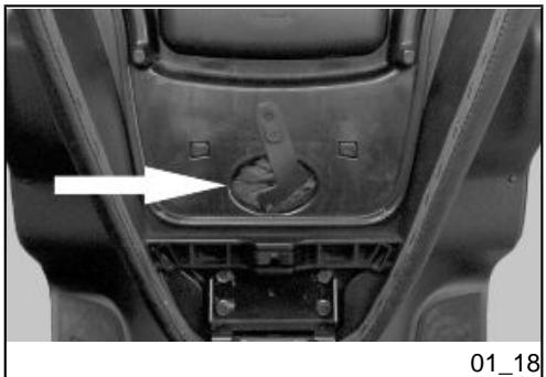
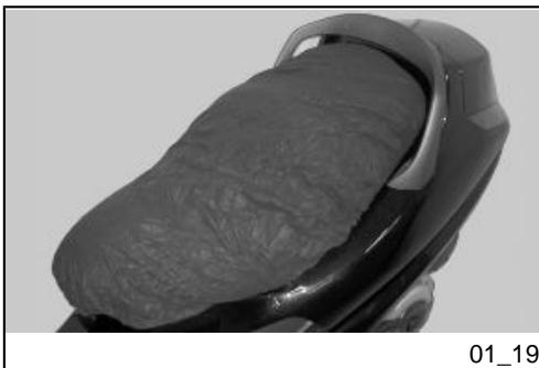
The saddle (01_18, 01_19)
The saddle is supplied with a protection cover which may be used in case of rain.
Lift the saddle and extract the cover from its housing, then extend it over the whole length of the saddle, starting from the front-end; do not over stretch the cover to avoid tearing the material; close the saddle.
CAUTION

DO NOT USE THE VEHICLE WITHOUT THE PROTECTION COVER.
Opening the saddle to access the helmet compartment by remote control
When the key is in «LOCK» or «OFF» position, the saddle and/or the rear glove-box can be opened with the remote control. The saddle cannot be opened only when the key is set to "ON".
CAUTION

OBJECTS INAPPROPRIATELY PLACED INSIDE THE HELMET COMPARTMENT MAY DEFORM THE SADDLE AND PREVENT THE COURTESY LIGHT FROM TURNING OFF, WHICH MAY RESULT IN BATTERY DISCHARGE.
WARNING
THE REMOTE CONTROL OPERATES WITHIN A DISTANCE OF ABOUT 100 METRES WITH FULLY CHARGED BATTERIES. WHEN YOU ARE NEAR THE VEHICLE, HANDLE THE REMOTE CONTROL CAREFULLY SO AS TO AVOID UNINTENTIONAL OPENING OF THE SADDLE AND/OR THE REAR GLOVE-BOX. REFER TO THE «OPENING THE SADDLE WITH REMOTE CONTROL» SECTION TO REPLACE BATTERIES.
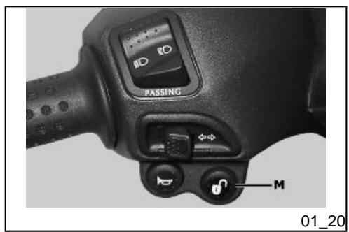
Opening the saddle (01_20)
With the key set to "OFF" or "ON" or with the engine on, you can electrically open the saddle by pressing button "M". If the electric opening does not work, use the emergency lever "A". When the key is set to "LOCK" the saddle cannot be opened.

OBJECTS INAPPROPRIATELY PLACED INSIDE THE HELMET COMPARTMENT MAY CAUSE THE SADDLE TO DEFORM AND MAY PREVENT THE COURTESY LIGHT FROM TURNING OFF.
HOWEVER, THIS IS SIGNALLED BY THE CORRESPONDING WARNING LIGHT Fitted ON THE INSTRUMENT PANEL
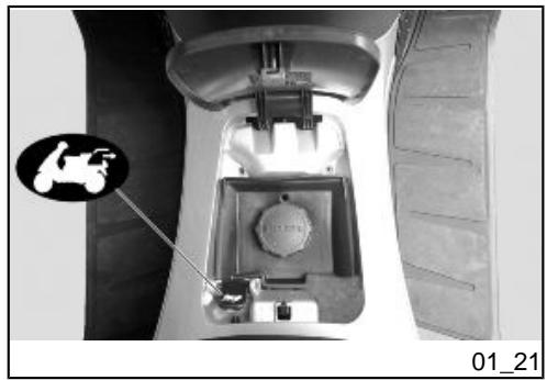
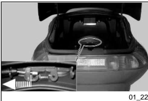
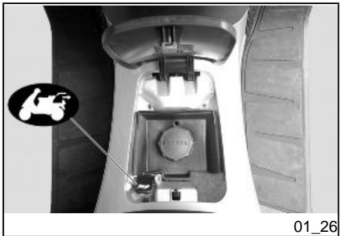
Opening the saddle to access the helmet compartment in an emergency (01_21, 01_22)
With the key in position "OFF" or "ON" it is possible to open the cover of the fuel tank filler neck.
Press the lever to open the rear compartment of the scooter.
To open the saddle it is necessary to press the metallic lever of the seat lock manually towards the left of the scooter (as seen in the direction of travel). For this operation you have to reach into the inside of the luggage compartment after having opened the rear cover.
WARNING

OBJECTS INAPPROPRIATELY PLACED INSIDE THE HELMET COMPARTMENT MAY DEFORM THE SADDLE AND PREVENT THE COURTESY LIGHT FROM TURNING OFF, WHICH MAY RESULT IN BATTERY DISCHARGE.
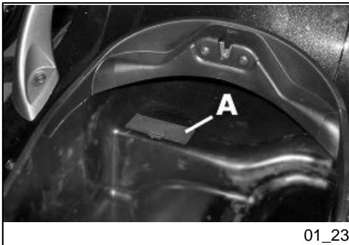
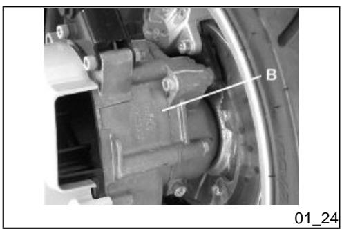
Identification (01_23, 01_24)
The identification registration numbers consist of a prefix stamped on the chassis and engine "B" respectively, followed by a number. These numbers must always be indicated on spare parts requests. To read the chassis number, remove the relevant port "A" in the helmet compartment placed under mat. We recommend checking that the chassis registration number stamped on the scooter corresponds with that on the scooter's documents.
CAUTION

BE REMINDED THAT ALTERING IDENTIFICATION REGISTRATION NUMBERS CAN LEAD TO SERIOUS PENAL SANCTIONS (IMPOUNDING OF THE VEHICLE, ETC.).
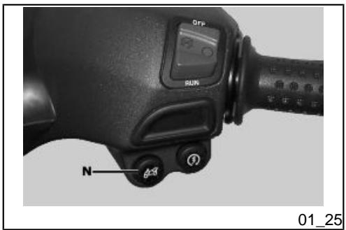
If the ignition key-switch is turned to either the "ON" or "OFF" position, or the engine is running, it is possible to open the boot door electrically, pressing button "N".
Should the electrical opening fail, please use the lever indicated located underneath the fuel tank filler neck.
X8 400 i.e.

PIAGGIO

Chap. 02 Use
Checks
Before using the vehicle, check:
- There is enough fuel in the fuel tank.
- The correct fluid level for front and rear brakes.
- That tyres are properly inflated.
- The correct functioning of tail lights, headlamp, turn indicators, stop light and license plate light.
- The correct functioning of front and rear brakes.
- The oil level in the gearcase.
- The engine oil level.
- The coolant level.
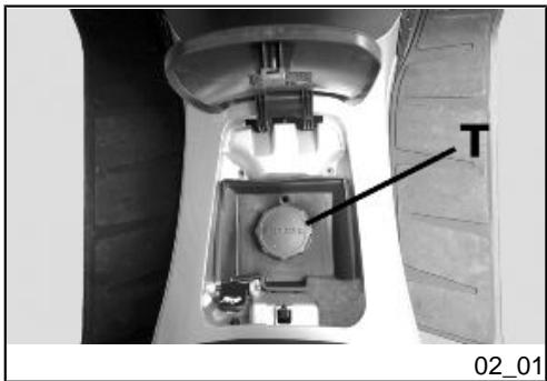
Refuelling (02_01, 02_02)
Fuel: By pressing the switch-key (with the key in «OFF» or «ON») open the tank cover to reach the fuel filler cap and remove it «T».
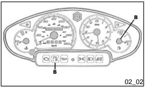
Recommended fuel: Unleaded petrol, min octane rating of 95. The fuel reserve level is indicated by the warning light and the digital gauge "B".
WARNING

SWITCH OFF THE ENGINE BEFORE REFUELLING WITH PETROL.
PETROL IS HIGHLY INFLAMMABLE.
DO NOT SMOKE AND KEEP OPEN FLAMES AT A DISTANCE:FIRE HAZARD.
DO NOT INHALE FUEL FUMES.
DO NOT ALLOW PETROL TO COME INTO CONTACT WITH HOT ENGINE OR ANY PLASTIC PARTS.
CAUTION

PETROL DAMAGES THE PLASTIC PARTS OF THE BODYWORK.
WARNING

DO NOT RIDE WITH THE FUEL TANK ALMOST EMPTY, LACK OF FUEL CAN DAMAGE THE CATALYTIC CONVERTER.
CAUTION

USING NON-RECOMMENDED PETROL REDUCES THE EFFICIENCY OF THE EXHAUST AND FUEL SUPPLY SYSTEMS.
WARNING

IT IS HIGHLY INADVISABLE TO REFUEL USING METHODS OTHER THAN NORMAL FUEL PUMPS. IF PETROL IS NOT COMPLETELY CLEAN, IT CAN DAMAGE THE FUEL SUPPLY SYSTEM FILTERS.
Characteristic
Fuel tank capacity
Fuel tank capacity: 12 l (approx.)
Fuel reserve
approx. 2.5 litres (indicative value)
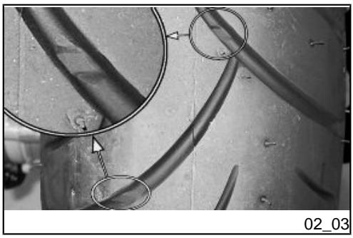
Tyre pressure (02_03)
Check the tyre pressure and wear periodically (roughly every 500~km ). The tyres are equipped with wear indicators; the tyres should be replaced as soon as these indicators become visible on the tyre tread. Also check that the tyres do not show signs of splitting at the side or irregular tread wear; if this occurs, go to an authorised workshop or at least a workshop equipped to perform the replacement.
CAUTION

TYRE PRESSURE SHOULD BE CHECKED WHEN TYRES ARE COLD.INCORRECT TYRE PRESSURE CAUSES ABNORMAL TYRE WEAR AND MAKES RIDING DANGEROUS.
TYRES MUST BE REPLACED WHEN THE TREAD REACHES THE WEAR LIMITS SET FORTH BY LAW.
Characteristic
Front tyre pressure
2.2 bar
Rear tyre pressure
2.4 bar
Rear wheel pressure (rider and passenger):
2.5 bar
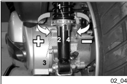
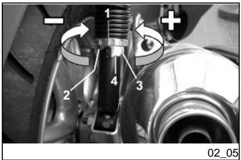
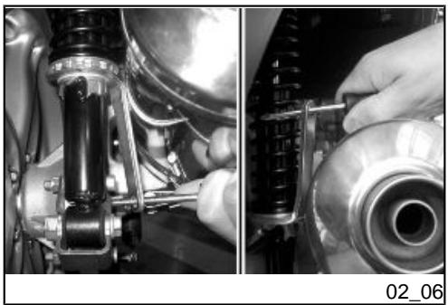
Shock absorbers adjustment (02_04, 02_05, 02_06)
The preloading of the springs can be adjusted to 4 positions using the ring nut located in the lower part of the shock absorbers and the specific spanner supplied.
Position 1: minimum preload: driver only
Position 2 medium preloading: driver only
Position 3 medium preloading: rider and passenger
Position 4: maximum preloading: driver, passenger, and luggage.
In order to carry out this operation you will need to use the specific spanner in the kit.
CAUTION

RIDING THE VEHICLE WITH THE SPRING PRELOADING NOT CORRECTLY SET FOR THE RIDER AND POSSIBLE PASSENGER, COULD REDUCE THE COMFORT OF THE RIDE AND THE PRECISION OF THE STEERING.
WARNING

WE RECOMMEND WEARING GLOVES WHILE CARRYING OUT THIS OPERATION IN ORDER TO AVOID INJURIES.
WARNING

WE STRONGLY RECOMMEND NOT TO ADJUST BOTH SHOCK ABSORBERS WITH DIFFERENT PRELOADING
Running in
DURING THE FIRST 1000 KM DO NOT RIDE THE VEHICLE OVER 80% OF ITS MAX. SPEED. AVOID OPENING THE THROTTLE GRIP COMPLETELY OR KEEPING A CONSTANT SPEED ALONG LONG SECTIONS OF ROAD. AFTER THE FIRST 1000 KM INCREASE SPEED PROGRESSIVELY, IF POSSIBLE, UNTIL THE MAXIMUM PERFORMANCE IS OBTAINED.
CAUTION

IN ORDER TO AVOID DAMAGING THE VEHICLE, PLEASE COMPLY WITH THE RULES LISTED ABOVE.
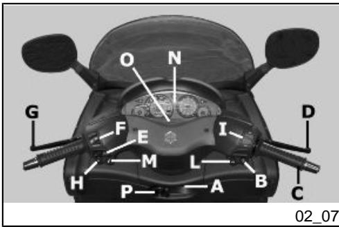
Starting up the engine (02_07)
The vehicle is supplied with an ignition cut-off system, activated by the emergency cut-off switch. The engine cannot be started if the ignition cut-off switch is in the OFF position
A running engine automatically switches off when the ignition cut-off switch is set to OFF.
The scooter is equipped with automatic transmission with direct drive, so that starting is effected by turning the throttle grip to idle speed; to start-off from still, progressively twist the throttle grip. The vehicle is equipped with an electrical fuel pump that switches on automatically as soon as the engine is started. In order to start the engine, it is necessary to pull either the front, "D", or the rear brake lever, "G", while pressing the starting button, "B", so to disengage the safety switches.
- Rest the vehicle on its centre-stand, ensuring the rear wheel is not touching the ground.
- Maintain the throttle "C" completely untwisted.
- Insert the key into the ignition switch "A" and turn it onto the ON position.
- Make sure that the "I" switch is set onto the ON position.
- Pull either the front, "D", or rear brake lever, "G", while pressing the starter button "B".
WARNING

THE AUTOMATIC TRANSMISSION MAKES THE REAR WHEEL TURN EVEN WHEN THE THROTTLE IS SLIGHTLY TWISTED. RELEASE THE BRAKE CAREFULLY AFTER STARTING, AND THEN ACCELERATE GRADUALLY.
CAUTION

DO NOT START-UP THE ENGINE IN CLOSED AREAS BECAUSE EXHAUST GASES ARE TOXIC.
CAUTION

DUE TO THE HIGH TEMPERATURES THE CATALYTIC CONVERTER CAN REACH, ALWAYS TAKE CARE, WHEN PARKING THE SCOOTER, THAT THE EXHAUST DOES NOT COME INTO CONTACT WITH FLAMMABLE MATERIALS, TO AVOID SERIOUS BURNS.
CAUTION

DO NOT SWITCH OFF THE ENGINE WHILE THE VEHICLE IS MOVING. UNBURNED FUEL COULD ENTER THE CATALYTIC CONVERTER AND BURN, CAUSING IT TO OVERHEAT AND POSSIBLY DESTROYING IT.
Precautions
CAUTION

NEVER STRESS THE ENGINE AT LOW TEMPERATURES IN ORDER TO AVOID POSSIBLE DAMAGE. BE CAREFUL NEVER TO EXCEED THE MAXIMUM SPEED WHILE RUNNING DOWNHILL, IN ORDER TO AVOID DAMAGING THE ENGINE. IN ANY CASE, IN ORDER TO PRESERVE THE ENGINE FROM PROLONGED EXCESSIVE REVOLUTIONS, THE REVOLUTION LIMITER WILL BE ACTIVATED IF THE ENGINE SPEED EXCEEDS THE ESTABLISHED THRESHOLD.
WARNING

AFTER A LONG DISTANCE COVERED AT THE MAXIMUM SPEED, DO NOT STOP THE ENGINE IMMEDIATELY, BUT LET IT RUN AT IDLE FOR A FEW SECONDS.
Difficult start up
In the rare event of a flooded engine, and to facilitate start-up, it is possible to attempt to operate start engine with the throttle partially or fully twisted. It is however necessary, once the engine is started, to visit an Authorised Piaggio Service Centre to determine the cause and make certain that the scooter functions properly.
In case of fuel exhaustion:After having refilled the scooter, start it, using the starter switch «A» and keeping the gas hand grip at the minimum. If you cannot start the scooter using the above methods then turn to an Authorised Piaggio-Gilera Service Centre.
Faulty battery and start-up with auxiliary battery: If the battery is dead it is possible to start the engine by means of a connection to another battery, with cables capable of accepting high current and with clamps at the ends. If the auxiliary battery is installed
in another scooter, do not allow the two scooters to touch and position them both on the centre stand (if the other scooter has one).
Proceed as follows:
a) Switch off all services and users, start up the vehicle with the auxiliary battery and make the engine run slightly above idle to ensure deep battery charge; then turn off the engine.
b) Set the vehicle key switch to "OFF".
c) Connect the positive terminal (+) of the discharged battery to the positive terminal (+) of the auxiliary battery, and the negative terminal (-) of the discharged battery to the negative terminal (-) of the auxiliary battery.
d) Try to start the scooter by alternating 5 seconds of turning the starter motor with 5 seconds of pause. If the motor does not start after 20^ of using the start-up system, do not continue with the attempt, since the scooter might not start due to some other problem.
e) Once the engine has started, keep it running slightly above idle and disconnect the cable (one cable at a time from both battery terminals) following the reverse mounting procedure: first the negative terminal (-) and then the positive one (+) . As soon as you can, control the electrolyte level (in the case of unsealed batteries) and top up with distilled water, if necessary. If the fault that causes the battery to discharge is unknown, contact an authorised Piaggio Service Centre to check the vehicle's electrical system.
Stopping the engine
Fully untwist the throttle grip, then rotate the key in the switch «A » to «KEY OFF» (extractable key).
CAUTION

DUE TO THE HIGH TEMPERATURES THE CATALYTIC CONVERTER CAN REACH, ALWAYS TAKE CARE, WHEN PARKING THE SCOOTER, THAT THE EXHAUST DOES NOT COME INTO CONTACT WITH FLAMMABLE MATERIALS, TO AVOID SERIOUS BURNS.
CAUTION

DO NOT SWITCH OFF THE ENGINE WHILE THE VEHICLE IS MOVING. UNBURNED FUEL COULD ENTER THE CATALYTIC CONVERTER AND BURN, CAUSING IT TO OVERHEAT AND POSSIBLY DESTROYING IT.
WARNING

TO START AFTER A LONG STATIONARY PERIOD, OR IN SEVERE WEATHER CONDITIONS, FULLY TWIST THE THROTTLE 2 ÷ 3 TIMES BEFORE PRESSING THE STARTER BUTTON.
Stand (02_08)
CENTRE STAND
Push with your foot on the centre stand's fork «F» while lifting the vehicle backward, holding onto the handlebar.
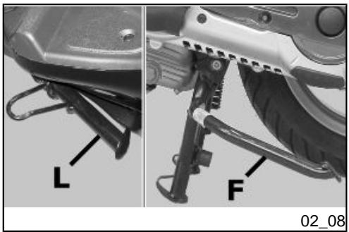
SIDE
Push with your foot on the fork of the stand "L" to bring it into the open position while lifting the scooter at the same time.
CAUTION

TAMPERING MAY CAUSE SERIOUS ENGINE MALFUNCTION.
WARNING
THE SIDE STAND CAUSES THE ENGINE TO CUT OUT EVERY TIME THAT IT IS LOWERED; THIS CONDITION IS INDICATED BY THE RESPECTIVE WARNING LIGHT ON THE INSTRUMENT PANEL.
Automatic transmission
To ensure simple, pleasurable riding, the vehicle is equipped with automatic transmission with regulator and centrifugal clutch. The system is designed to provide the best performance (acceleration and consumption) while riding on both flat roads and uphill.
If you have to stop on an uphill slope (traffic lights, traffic jam, etc.) use only the brake to keep the vehicle still, leaving the engine running at idle speed. Using the engine to keep the vehicle still can cause the clutch to overheat, due to the friction of the clutch mechanism itself against the clutch bell.
It is therefore recommended to avoid conditions of prolonged clutch slippage (other than those previously indicated) like driving uphill fully laden on steep slopes or starting off with driver and passenger at slopes with steepness greater than 25% .
Observe the following precautions if the clutch overheats:
-
Do not continue riding in such conditions.
-
Let the clutch cool down with the engine at idle speed for a few minutes.
Safe driving
Some simple tips are provided below that will enable you to use your vehicle on a daily basis in greater safety and peace of mind. Your skill and your mechanical knowledge are the basis of safe riding. We recommend trying out the vehicle in traffic - free zones, in order to acquire a good knowledge of the vehicle it self.
- Before riding off, remember to put on your helmet and fasten it correctly.
- Reduce speed on rough roads and drive with care.
- After riding on a long stretch of wet road without using the brakes, braking can be poor at the beginning. Given these conditions, it is a good idea to operate the brakes from time to time.
- Do not brake hard on wet, dirt or slippery road surfaces.
- Avoid riding off by mounting the scooter when resting on the support. In any case, the rear wheel should not be turning when in comes into contact with the ground, in order to avoid abrupt departures.
- When riding along roads covered by sand, mud, snow mixed with salt, etc. we recommend cleaning the brake disc frequently with a non-corrosive detergent in order to prevent corrosive particles from building up in the holes, which may cause early brake pad wear.
CAUTION

ALWAYS RIDE WITHIN YOUR LIMITS RIDING UNDER THE INFLUENCE OF ALCOHOL OR OTHER DRUGS AND CERTAIN MEDICATIONS IS EXTREMELY DANGEROUS.
CAUTION

IN ORDER TO PREVENT ANY ACCIDENTS RIDE VERY CAREFULLY AFTER ADDING ACCESSORIES AND WHILE CARRYING LUGGAGE. ADDING ACCESSORIES AND LUGGAGE CAN REDUCE THE VEHICLE'S STABILITY, PERFORMANCE AND SAFETY DURING USE.
WARNING

NEVER RIDE THE SCOOTER EQUIPPED WITH ACCESSORIES (TOP BOX AND/ OR WINDSHIELD) AT A SPEED HIGHER THAN 100km / h .
THE SCOOTER CAN BE RIDEN AT A HIGHER SPEED WITHOUT THE ACCESSORIES MENTIONED BEFORE WITHIN THE LIMITS ESTABLISHED BY LAW.
IF THERE SHOULD BE NON-PIAGGIO ACCESSORIES INSTALLED, OR AN AB-NORMAL LOAD, OR IF THE SCOOTER IS NOT IN A GENEALLY GOOD CONDITION, OR WHENEVER WEATHER CONDITIONS DEMAND IT, SPEED SHOULD BE REDUCED FURTHER.
CAUTION

DO NOT ADJUST THE MIRRORS WHILE RIDING. THIS COULD CAUSE YOU TO LOOSE CONTROL OF THE VEHICLE.
CAUTION

ANY CHANGES TO THE VEHICLE PERFORMANCE AS WELL AS ALTERATIONS TO ORIGINAL STRUCTURAL PARTS IS STRICTLY FORBIDDEN BY LAW, AND
RENDERS THE VEHICLE NO LONGER CONFORMING TO THE APPROVED TYPE AND DANGEROUS FOR RIDING.
X8 400 i.e.

PIAGGIO
Chap. 03 Maintenance
Engine oil level
In 4-stroke engines, engine oil is used to lubricate the distribution elements, the bushes and the thermal group. An insufficient quantity of oil can cause serious damage to the engine. In all four-stroke engines, a loss of efficiency in oil performance and consumption should be considered normal. Consumption can particularly reflect the conditions of use (i.e. when driving at "full acceleration" all the time, oil consumption increases). The replacement frequencies provided for by the maintenance programme are defined, depending on the total contents of oil in the engine and average consumption measured following standardised methods.
In order to prevent any problems, we recommend checking oil level more frequently than indicated in the Scheduled Maintenance table or before setting off on long journeys. The scooter is, however, equipped with an oil pressure warning light on the instrument panel.
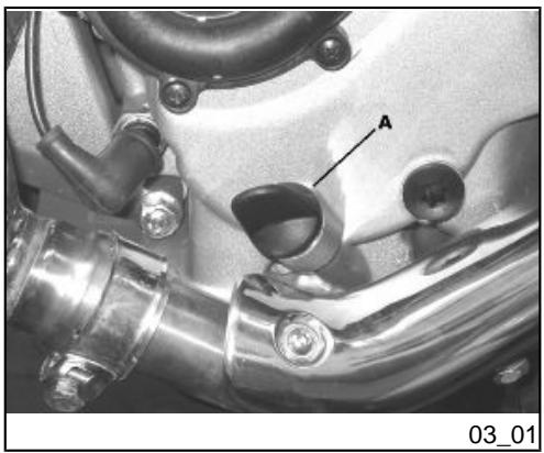
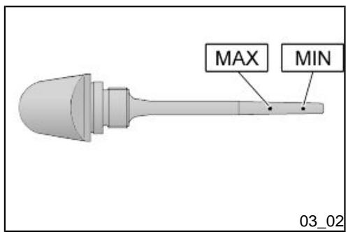
Engine oil level check (03_01, 03_02)
This operation must be carried out with the engine cold and following the procedure below:
1) Rest the scooter on the central stand and on a flat ground.
2) Set the strut that regulates the position to its minimum height.
3) Screw off cap/dipstick «A», dry it off with a clean cloth and reinsert it, screwing down completely.
4) Remove the cap/dipstick «A» again and check that the level is between the MAX and MIN marks; top up, if required.
The MAX level as shown in the figure indicates that there is about 1700 cc of oil in the engine. If the check is carried out after the vehicle has been used, and therefore with a hot engine, the level line will be lower; in order to carry out a correct check it is necessary to wait at least 10 minutes after the engine has been stopped, so as to get the correct level.
Engine oil top-up
Any topping up with oil must be carried out after the oil level check by adding oil, but never exceeding the MAX level. The topping up of the level between MIN and MAX requires approx. 200 cc of oil. Every 5000km , however, the engine oil level should be checked and topped up, if necessary, at an Authorised Piaggio Service Centre.
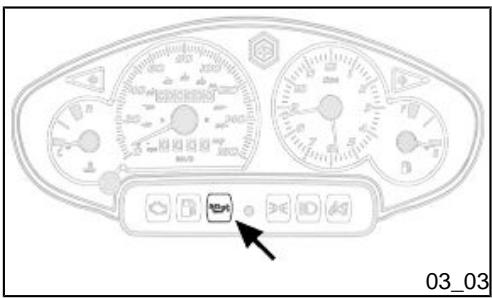
Warning light (insufficient oil pressure) (03_03)
The vehicle is equipped with a warning light that lights up when the key is turned to the «ON». However, this light should switch off once the engine has been started. If the light comes on while braking, at idle speed or while turning a corner, it is necessary to check the oil level and top it up if required. If after having topped-up the oil, the warning light still comes on while braking, at idle speed or while turning a corner, it will be necessary to take your vehicle to an Authorised Service Centre.
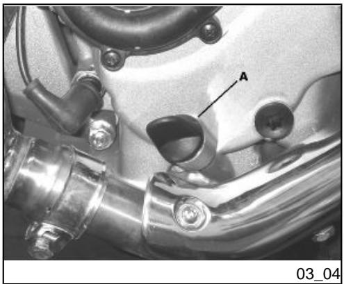
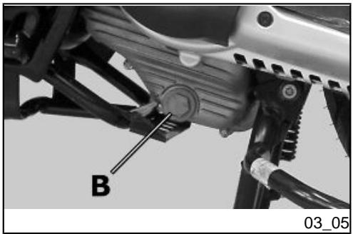
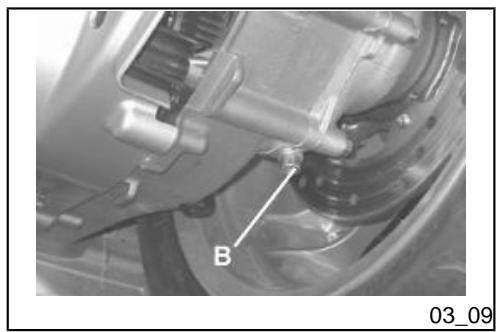
Engine oil change (03_04, 03_05, 03_06)
The engine oil and filter must be replaced every 6,000km at an Authorised Piaggio-Gilera Service Centre. The engine should be emptied by draining the oil via the drainage tap «B» of the mesh filter on the transmission side. In order to facilitate oil drainage, loosen the cap/dipstick «A». Unscrew and remove the oil cartridge filter. Install a new oil filter taking care to lubricate the sealing O-rings with engine oil. Since a certain quantity of oil still remains in the circuit, add approx. 1500 cc of oil through cap "A". Then start up the scooter, leave it running for a few minutes and switch it off: after five minutes, check the level and if necessary top up without exceeding the MAX. level. The cartridge filter must be replaced at every oil change. For top-ups and oil changes, use new oil of the recommended type.
CAUTION

RUNNING THE ENGINE WITH INSUFFICIENT LUBRICATION OR WITH INADEQUATE LUBRICANTS ACCELERATES THE WEAR AND TEAR OF THE MOVING PARTS AND CAN CAUSE IRRETRIEVABLE DAMAGE.
TOPPING UP THE ENGINE WITH AN EXCESSIVE AMOUNT OF OIL MAY CAUSE MALFUNCTION AND/OR A DROP IN PERFORMANCE OF THE VEHICLE.
USING OILS OTHER THAN THOSE RECOMMENDED CAN SHORTEN THE LIFE OF THE ENGINE.
CAUTION

USED OILS CONTAIN SUBSTANCES HARMFUL TO THE ENVIRONMENT. FOR OIL REPLACEMENT, CONTACT AN AUTHORISED SERVICE CENTRE, WHICH IS EQUIPPED TO DISPOSE OF USED OILS IN AN ENVIRONMENTALLY FRIENDLY AND LEGAL WAY.
Recommended products
AGIP CITY HI TEC 4T
Four-stroke engine oil

Lubricating oil for flexible shafts (throttle control)
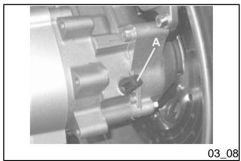
Hub oil level (03_07, 03_08, 03_09)
Check the oil in the rear hub.
To check the rear hub oil level, proceed as follows:
1.Park the scooter on level ground and rest it on its centre stand.
2. Unscrew the oil dipstick «A», dry it with a clean cloth. Reinsert it and screw it tightly into place.
3. Pull out the dipstick and check that the oil level is between the MIN and MAX reference marks. If the oil level is below the MIN notch, top up with the required amount of hub oil.
4. Screw the dipstick back in, checking that it is locked in place.
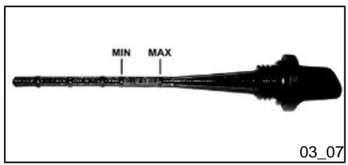
The notches on the hub oil level dipstick, apart from that indicating the MAX level, refer to other models from the manufacturer and have no specific function for this model.
CAUTION

RIDING THE VEHICLE WITH INSUFFICIENT HUB LUBRICATION OR WITH CONTAMINATED OR IMPROPER LUBRICANTS ACCELERATES THE WEAR AND TEAR OF THE MOVING PARTS AND CAN CAUSE SERIOUS DAMAGE.
CAUTION

USED OIL CAN HARM THE ENVIRONMENT. COLLECTION AND DISPOSAL SHOULD BE CARRIED OUT IN COMPLIANCE WITH CURRENT REGULATIONS.
CAUTION

AN EXCESSIVE QUANTITY OF OIL CAN LEAD TO SPILL OVER, WHICH MAY CAUSE THE ENGINE AND THE WHEEL TO GET DIRTY.
CAUTION

UPON REPLACING HUB OIL, AVOID THE OIL COMING INTO CONTACT WITH THE REAR BRAKE DISC.
CAUTION

FOR OIL REPLACEMENT, CONTACT ANY AUTHORISED SERVICE CENTRE AS THEY ARE EQUIPPED TO DISPOSE OF USED OILS IN AN ENVIRONMENTALLY FRIENDLY AND LEGAL WAY.
Recommended products
AGIP ROTRA 80W-90
Rear hub oil
SAE 80W/90 Oil that exceeds the requirements of API GL3 specifications
Characteristic
Quantity:
approx. 250 cc
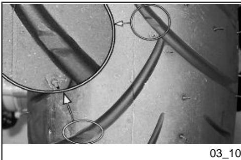
Tyres (03_10)
WARNING

THE WHEELS FITTED WITH TYRES SHOULD ALWAYS BE BALANCED. RIDING THE VEHICLE WITH VERY LOW TYRE PRESSURE OR WITH INCORRECTLY BALANCED TYRES CAN LEAD TO DANGEROUS STEERING VIBRATIONS.
CAUTION

THE USE OF TYRES OTHER THAN THOSE INDICATED MAY CAUSE INSTABILITY. IT IS HIGHLY ADVISIBLE TO USE ORIGINAL PIAGGIO TYRES.
CAUTION

TYRE PRESSURE SHOULD BE CHECKED WHEN TYRES ARE COLD.INCORRECT TYRE PRESSURE CAUSES ABNORMAL TYRE WEAR AND MAKES RIDING DANGEROUS.
TYRES MUST BE REPLACED WHEN THE TREAD REACHES THE WEAR LIMITS SET FORTH BY LAW.
Characteristic
Front tyre pressure
2.2 bar
Rear tyre pressure
2.4 bar
Rear wheel pressure (rider and passenger):
2.5 bar
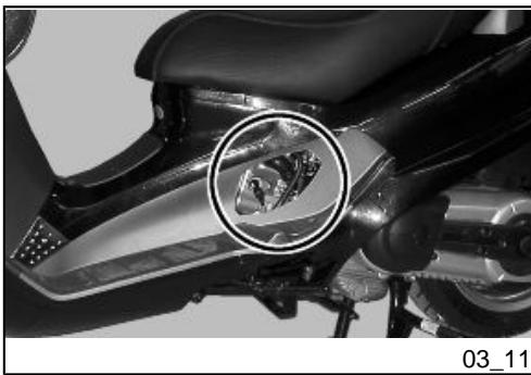
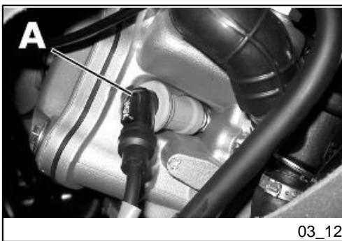
Spark plug dismantlement (03_11, 03_12)
Proceed as follows:
- Remove the lid to access the spark plug and reach it with your hand;
- Disconnect spark plug HV wire cap «A»;
- Unscrew the spark plug using the spark plug wrench supplied;
- When refitting, place the spark plug into the hole at the required angle and tighten by hand until it is finger tight;
- Use the wrench only for final tightening of the spark plug;
- Place hood "A" fully over the spark plug.
N.B.
THE USE OF SPARK PLUGS OTHER THAN THE INDICATED TYPE OR OF SHIELDLESS SPARK PLUG CAPS CAN CAUSE ELECTRICAL SYSTEM FAILURES.

THE SPARK PLUG MUST BE REMOVED WHEN THE ENGINE IS COLD. SPARK PLUG REPLACEMENT OPERATIONS ARE DESCRIBED IN THE SCHEDULED MAINTENANCE TABLE
THE USE OF ELECTRONIC CONTROL UNITS OR NON-COMPLIANT ELECTRONIC IGNITION SYSTEMS AND/OR SPARK PLUGS OTHER THAN THOSE PRESCRIBED MAY SERIOUSLY DAMAGE THE ENGINE.
IF THE SPARK PLUG NEEDS TO BE REMOVED AFTER A FLOODED ENGINE SITUATION, IT IS ADVISIBLE TO KEEP THE TUBE CONNECTED TO THE SPARK PLUG, AND THIS IN TURN TO A GROUND POINT AWAY FROM THE SPARK PLUG HOLE TO AVOID OUTGOING PETROL FROM CATCHING FIRE.
Characteristic
Spark plug
NGK CR7EKB
Electrode gap
0.7-0.8 mm
Locking torques (N^*m)
spark plug
12 to 14 Nm
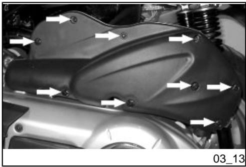
Removing the air filter (03_13)
Proceed as follows:
- Remove the LHS fairing;
- Loosen the screws "A" (two of which have a knob-type head) and remove the air filter cover.
Air filter cleaning
- Wash the sponge with water and neutral soap.
- Dry it with a clean cloth and small blasts of compressed air.
- Impregnate the sponge with a mixture of 50% petrol and 50% specified oil.
- Gently squeeze the filter element, let it drip and then refit it.
CAUTION

IF THE VEHICLE IS USED ON DUSTY ROADS, IT IS NECESSARY TO SERVICE THE AIR FILTER MORE OFTEN TO AVOID DAMAGING THE ENGINE.
Recommended products
AGIP FILTER OIL
Oil for air filter sponge
Mineral oil with specific additives for increased adhesiveness
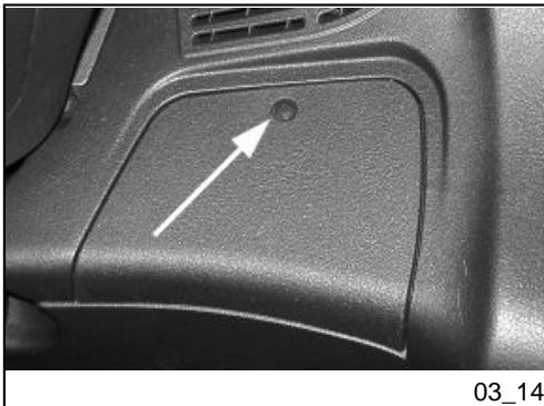
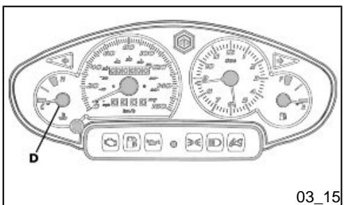
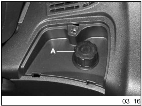
Cooling fluid level (03_14, 03_15, 03_16, 03_17)
The engine cooling system is of the forced liquid circulation type. The coolant circuit contains approx. 1.8 litres of coolant consisting of a mixture of 50% demineralised water and glycol ethylene-based antifreeze solution with corrosion inhibitors.
The liquid supplied with the scooter is already mixed and ready for use.
For the engine to work properly, the coolant temperature must range between a minimum value of 60^ and a maximum value of 105^ , as indicated by the instrument "D" on the analogue instrument panel by coloured references. If the pointer enters into the red zone, stop the engine, let it cool down and check the fluid level; if the result is normal, turn to an Authorised Piaggio Service Centre.
The fluid inspection should be carried out every 6,000km when the engine is cold, following the methods indicated below.
a) Rest the scooter on its centre stand, on flat ground.
b) Remove the filler cap cover by loosening the screw shown in the figure.
c) Remove the plug from expansion tank "A" by turning it counter clockwise.
d) Look into the expansion tank: a mark on the plastic part indicates the maximum and minimum reference of the expansion tank.
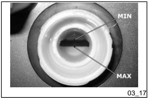
e) Top up the cooling fluid if the fluid level is below the minimum level margin inside the expansion tank.
The fluid level must always be between MIN and MAX level
If the fluid is near the minimum level, proceed with the top-up operation to be carried out when the engine is cold. If it is necessary to top up the coolant frequently, or if the expansion tank is completely dry, you should look for the cause in the cooling system. It is therefore indispensable to have the cooling system checked at an Authorised Piaggio Service Centre.
The coolant should be replaced every 2 years. For this operation, please contact an authorised Piaggio service centre.
N.B.
IF DURING A NON-DEMANDING RIDE THE COOLANT WARNING LIGHT COMES ON, SHUT OFF THE ENGINE AND ALLOW IT TO COOL DOWN. THEN CHECK THE COOLANT LEVEL; IF THE LEVEL IS NOT CORRECT, CONTACT AN AUTHORISED SERVICE CENTRE.
WARNING

WHENEVER REFITTING THE EXPANSION TANK FILLER CAP, PLEASE ENSURE IT IS CORRECTLY TIGHTENED SO AS TO AVOID LEAKAGE IN THE CIRCUIT.
WARNING

TO AVOID THE RISK OF SCALDING, DO NOT UNSCREW THE EXPANSION TANK COVER WHILE THE ENGINE IS STILL HOT.
WARNING

IN ORDER TO AVOID HARMFUL FLUID LEAKS WHILE RIDING, IT IS IMPORTANT TO MAKE SURE THAT THE LEVEL NEVER EXCEEDS THE MAXIMUM VALUE.
IN ORDER TO GUARANTEE THE PROPER FUNCTION OF THE ENGINE, IT IS NECESSARY TO KEEP THE RADIATOR GRILLE CLEAN.
Recommended products
AGIP PERMANENT SPEZIAL
coolant
Monoethylene glycol-based antifreeze fluid, CUNA NC 956-16
03_18
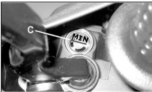
Checking the brake oil level (03_18)
The front and rear brake fluid reservoirs are both positioned on the handlebars. Proceed as follows:
- Place the scooter on its centre stand and make sure the handlebar is centred;
- Check the fluid through the specific sight glass «C».
A certain lowering of the level is caused by wear on the pads. Should the level appear to be below the minimum mark, please contact an Authorised Service Centre or Dealer in order to have braking system thoroughly checked.
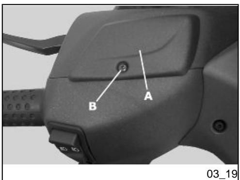
Braking system fluid top up (03_19)
Proceed as follows:
Loosen the screw "B" and lift the plastic cover "A" in order to access the brake fluid reservoir. Loosen the two fixing screws and remove the reservoir cover; top-up with the recommended fluid without exceeding the 'MAX.' mark.
This procedure applies to the rear brake pump top-up operation; follow the same procedure for the front brake pump.
Under normal climatic conditions, the fluid must be changed every 20,000 km or any way every two years.
This operation must be carried out by trained technicians; please contact your nearest Authorised PIAGGIO Dealer or Service Centre.
WARNING

ONLY USE DOT 4 CLASS BRAKE FLUIDS. COOLING SYSTEM FLUIDS ARE HIGHLY CORROSIVE. MAKE SURE THAT IT DOES NOT COME INTO CONTACT WITH THE PAINTWORK
CAUTION

AVOID CONTACT OF BRAKE FLUID WITH EYES, SKIN, AND CLOTHING. IN CASE OF CONTACT, RINSE WITH WATER. THE BRAKING CIRCUIT FLUID IS HYGROSCOPIC, THAT IS, IT ABSORBS HUMIDITY FROM THE SURROUNDING AIR. IF THE HUMIDITY IN THE BRAKING FLUID EXCEEDS A CERTAIN VALUE, IT WILL LEAD TO INEFFICIENT BRAKING. NEVER USE BRAKING FLUID KEPT IN CONTAINERS THAT HAVE ALREADY BEEN OPENED, OR PARTIALLY USED.
Recommended products
AGIP BRAKE 4
Brake fluid
FMVSS DOT 4 Synthetic fluid
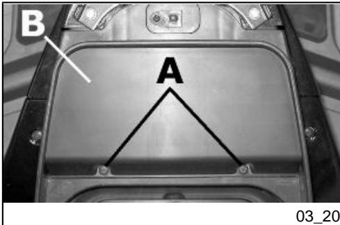
Battery (03_20)
To access the battery, proceed as follows:
- Place the scooter on its centre stand;
- Open the saddle, following the previously described procedure;
- Remove the two fasteners "A" and the cover "B".
The battery is the electrical device that requires the most frequent inspections and diligent maintenance. The main points of maintenance to be observed are as follows:
CAUTION

IN ORDER TO AVOID DAMAGING THE ELECTRICAL SYSTEM, NEVER DISCONNECTION THE WIRING WHILE THE ENGINE IS RUNNING. DO NOT TIP THE SCOOTER TOO MUCH IN ORDER TO AVOID DANGEROUS LEAKAGE OF BATTERY ELECTROLYTE
Use of a new battery
Make sure that the terminals are connected correctly.
CAUTION

DO NOT REVERSE THE POLARITY: RISK OF SHORT CIRCUIT AND DAMAGE TO THE ELECTRICAL SYSTEM.
WARNING

SPENT BATTERIES ARE HARMFUL FOR THE ENVIRONMENT. COLLECTION AND DISPOSAL SHOULD BE CARRIED OUT IN COMPLIANCE WITH CURRENT REGULATIONS.
Checking the electrolyte level
The electrolyte level, which should be checked regularly, must always be at the maximum level. To reach this level, use only distilled water. Should it become necessary to top up the battery with water too frequently, check the scooter's electrical system because the battery is being overloaded, causing it to lose power quickly.
CAUTION

ELECTROLYTE CONTAINS SULPHURIC ACID: AVOID CONTACT WITH EYES, SKIN AND CLOTHES. IN THE CASE OF ACCIDENTAL CONTACT, RINSE WITH ABUNDANT OF WATER AND CONSULT A DOCTOR.
Long periods of inactivity
If the vehicle has not been used for long periods, it is necessary to periodically recharge the battery, bearing in mind that the battery tends to go completely flat within around three months. The battery must be recharged with a current load equal to 1/10 of the battery rated capacity (~ 1A ) for a period not longer than 8 hours. Contact an Authorised Service Centre to carry out this operation safely. When refitting a removed battery, make sure that all terminals and the vent pipe are properly connected.
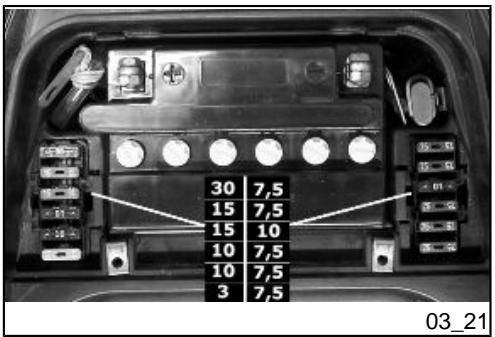
Fuses (03_21)
The electrical system is equipped with 12 protective fuses for the various circuits on the scooter, subdivided into two fuse boxes located alongside the battery.
The chart shows the position and characteristics of the fuses in the vehicle.
CAUTION

NEVER TRY TO REPLACE A BLOWN FUSE WITH A FUSE OF A DIFFERENT RATING THAN THAT SPECIFIED OR USING OTHER MATERIAL (FOR EXAMPLE, A PIECE OF ELECTRICAL WIRE).
BESIDES, IF AFTER REPLACING A FUSE, THE NEW FUSE ALSO BLOWS, THE SCOOTER NEEDS TO BE TAKEN TO AN AUTHORISED PIAGGIO/GILERA SERVICE CENTRE TO IDENTIFY THE CAUSE OF THE FAULT AND AVOID FURTHER DAMAGE TO THE ELECTRIC SYSTEM COMPONENTS OR THE VEHICLE ITSELF.
CAUTION

MODIFICATIONS OR REPAIRS TO THE ELECTRICAL SYSTEM, PERFORMED INCORRECTLY OR WITHOUT STRICT ATTENTION TO THE TECHNICAL SPECIFICATIONS OF THE SYSTEM, CAN CAUSE ERRORS IN FUNCTIONING AND RISK OF FIRE.
FUSE TABLE
| Fuse No. 1 | Threshold of operation: 30 A
Location: Battery compartment on the left side
Protected circuits: Battery charge |
| Fuse No. 2 | Threshold of operation: 15A
Location: Battery compartment on the left side
Protected circuits: Lines protected by fuses 8, 9, 10,12 - Engine stop remote control |
| Fuse No. 3 | Threshold of operation: 15A
Location: Battery compartment on the left side
Protected circuits: 12V 180W socket - Wiring for anti-theft device - Electrical fan remote control - Saddle opening control unit - Actuator for opening saddle and glove-box |
| Fuse No. 4 | Threshold of operation: 10 A
Location: Battery compartment on the left side
Protected circuits: Remote control for injection components (fuel pump, injector, h.v. coil.) |
| Fuse No. 5 | Threshold of operation: 10 A
Location: Battery compartment on the left side
Protected circuits: Headlight remote control - Bulb for helmet compartment light - Warning light for saddle/rear compartment cover open |
| Fuse No. 6 | Threshold of operation: 3 A
Location: Battery compartment on the left side
Protected circuits: Ignition ECU - Immobilizer decoder |
| Fuse No. 7 | Threshold of operation: 7.5A
Location: Battery compartment on the right side
Protected circuits: Instrument panel - Wiring for radio |
| Fuse No. 8 | Threshold of operation: 7.5A
Location: Battery compartment on the right side
Protected circuits: Saddle opening control unit - Turn indicator remote control |
| Fuse No. 9 | Threshold of operation: 10 A
Location: Battery compartment on the right side
Protected circuits: Headlight remote control - Start-up remote control - Stop light bulbs |
| Fuse No. 10 | Threshold of operation: 7.5A
Location: Battery compartment on the right side
Protected circuits: Horn - Taillight and license plate light bulbs - Instrument panel |
| Fuse No. 11 | Threshold of operation: 7.5A
Location: Battery compartment on the right side |
| Protected circuits: Remote control for injection components (fuel pump, injectors, h.v. coil.) - Electrical fan remote control - Ignition ECU - Immobilizer decoder |
| Fuse No. 12 | Threshold of operation: 7.5A
Location: Battery compartment on the right side
Protected circuits: Wiring for radio - Wiring for anti-theft device - Instrument panel |
LIGHT BULBS TABLE
| High-beam light bulb | Type: HALOGEN (H7) |
| Power: 12V - 55W |
| Quantity: 1 |
| Low-beam bulb | Type: HALOGEN (H1) |
| Power: 12V - 55W |
| Quantity: 1 |
| Front tail light bulb | Type: ALL GLASS |
| Power: 12V - 5W |
| Quantity: 2 |
| Instrument panel bulb | Type: ALL GLASS
Power: 12V - 1.2W
Quantity: 4 |
| Clock light bulb | Type: ALL GLASS
Power: 12V - 2W
Quantity: 1 |
| Front turn indicator bulb | Type: ALL GLASS
Power: 12V - 5W
Quantity: 2 RHS + 2 LHS |
| Helmet compartment light bulb | Type: CYLINDRIC
Power: 12V - 5W
Quantity: 1 |
| Rear turn indicator light bulb | Type: ALL GLASS
Power: 12V - 5W
Quantity: 2 RHS + 2 LHS |
| Rear tail light bulb | Type: ALL GLASS
Power: 12V - 5W
Quantity: 2 |
| Stop light bulb | Type: SPHERICAL
Power: 12V - 10W
Quantity: 2 |
| License plate light bulb | Type: ALL GLASS
Power: 12V - 5W
Quantity: 1 |
| 12V - 1.2W warning light bulb | Type: ALL GLASS
Application: Lighting system warning light - Full beam headlamp warning light - Open boot warning light - Injection warning light
Quantity: 4 |
| 12V - 2W warning light bulbs | Type: ALL GLASS
Application:Fuel reserve
Quantity: 1
Application: Turn indicators
Quantity: 2 |
| 12V - 3W warning light bulbs | Type: ALL GLASS
Application:Engine oil pressure
Quantity: 1 |
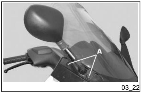
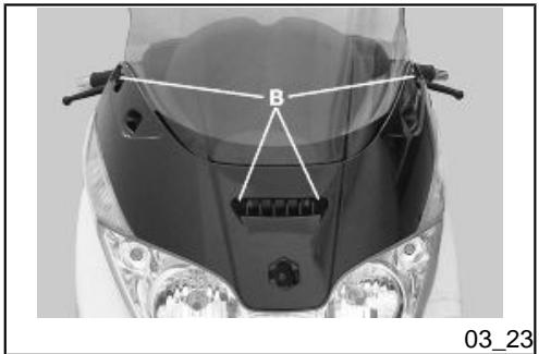
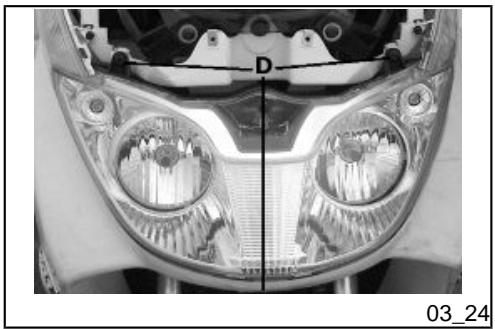
Front light group (03_22, 03_23, 03_24)
To remove the rear light assembly, proceed as follows:
- Remove the mirror cover, fastened by the two top screws and retained by the lower rubber ring joining it to the lower fairing;
- Remove both driving mirrors by loosening the fixing screws "A" on the right and left hand-side;
- Loosen the four fixing screws "B" and then remove the headlight cover;
- Extract the headlight from it housing by loosening the three fixing screws "D"; To reassemble, repeat the operation in the reverse order.
WARNING

HIGH AND LOW BEAM LIGHT ARE OF THE HALOGEN TYPE: DO NOT TOUCH WITH YOUR FINGERS TO AVOID DAMAGING THEIR FUNCTION.
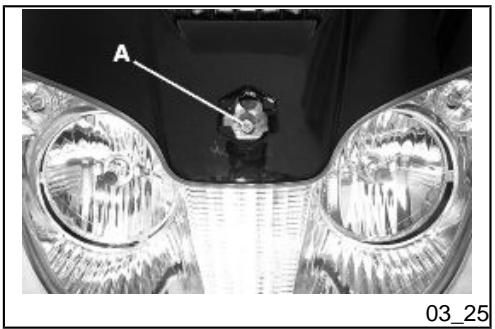
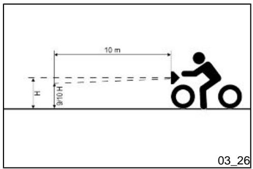

Headlight adjustment (03_25, 03_26)
Proceed as follows:
- Position the unloaded scooter, in running order and with the tyres inflated to the prescribed pressure, on a flat surface 10m away from a half-lit white screen; ensure that the longitudinal axis of the scooter is perpendicular to the screen;
- Turn on the headlight and check that the borderline of the projected light beam should be lower than 9/10 of the distance from the ground to the centre of the vehicle's headlight, and higher than 7/10;
- If not, adjust the projection by turning the central screw «A» set inside the glove box.
N.B.
THE ABOVE PROCEDURE COMPLIES WITH THE EUROPEAN STANDARDS REGARDING MAXIMUM AND MINIMUM HEIGHT OF LIGHT BEAMS. REFER TO THE STATUTORY REGULATIONS IN FORCE IN EVERY COUNTRY WHERE THE vehicle IS USED.
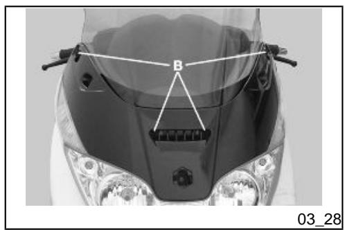
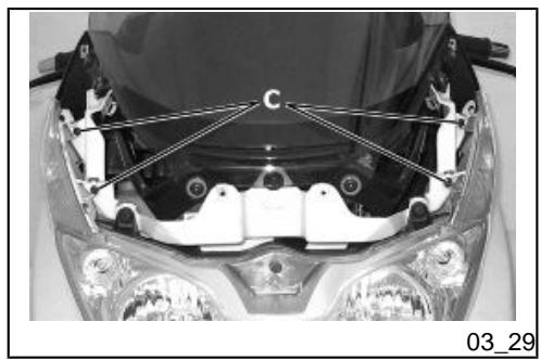
Front direction indicators (03_27, 03_28, 03_29)
To replace a burst bulb:
- Remove the driving mirrors, by lifting the cover and loosening the two screws "A" on both sides.
- Remove the front turn indicator light assembly cover, by loosening the four fixing screws "B".
- By loosening the two fixing screws "C" remove the turn indicator light;
To reassemble, repeat the operation in the reverse order.
WARNING

HIGH AND LOW BEAM LIGHT ARE OF THE HALOGEN TYPE: DO NOT TOUCH WITH YOUR FINGERS TO AVOID DAMAGING THEIR FUNCTION.
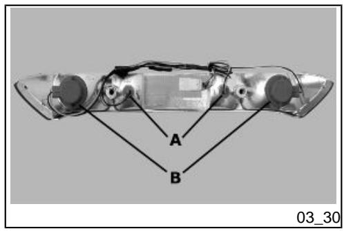
Rear optical unit (03_30, 03_31)
Open the rear flap (boot door), loosen the two fixing screws, "D", and remove the taillight assembly from its housing.
Follow this procedure to remove the bulbs:
Side lights - Snap-on central bulb " A"
Stop lights - Side bulbs "B" in bayonet socket making a 30^ clockwise turn.
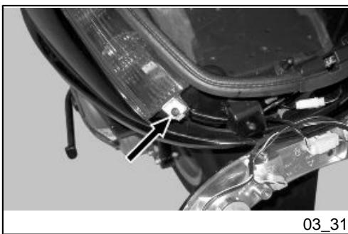
Rear turn indicators (03_31)
Detach the taillight to reach the fixing screw of the turn indicator.
Detach the rubber bulb holder and slide the burned out bulb off the bayonet joint.
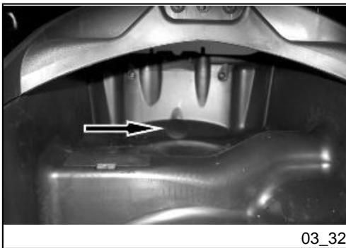
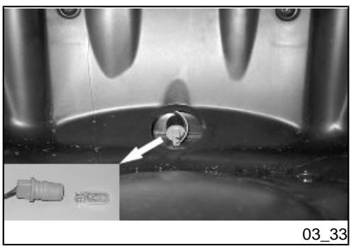
Number plate light (03_32, 03_33)
Follow these instructions to replace the license plate light bulb:
- Remove the rubber cap at the back of the helmet compartment.
- Remove the rubber bulb holder from its housing; then take the bulb off the holder and replace it.
- Install the bulb holder in its position on the mudguard and mount the rubber cap back.
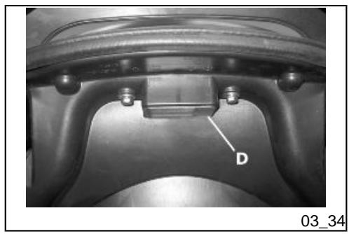
Helmet compartment lighting bulb (03_34)
Open the rear boot and insert a small plain slot screwdriver in the lateral notch to detach the snap-on glass "D", then replace the bulb.
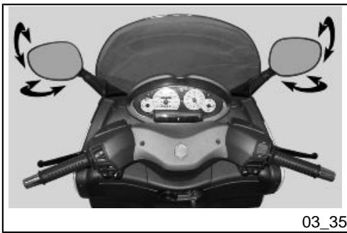
Rear-view mirrors (03_35)
The mirrors can be set to the desired position by adjusting the mirror frame.
Front and rear disc brake
The brake disc and pad wear is automatically compensated, therefore it has no effect on the functioning of the front and rear brakes. For this reason it is not necessary to adjust the brakes. An excessively elastic brake lever stroke may indicate the presence of air in the braking circuit or a failure in the braking system. In this case, mainly due to the importance of brakes to guarantee safe riding conditions, the vehicle should be taken to an Authorised Service Centre or Dealer.
CAUTION

The vehicle is equipped with Tubeless tyres (without inner tube). In the event of a puncture, contrary to the situation with a tyre with inner tube, the tyre deflates more slowly, resulting in a greater steering safety. In the event of a puncture, it is admissible to make an emergency repair using an "inflate and repair" spray can. For a final repair, take your vehicle to an Authorised Service Centre or Dealer. The replacement of a tyre involves removing the wheel in question. Take your vehicle to an Authorised Service Centre or Dealer for these operations.
CAUTION

TO USE THE "INFLATE AND REPAIR" SPRAY PROPERLY FOLLOW THE INSTRUCTIONS ON THE PACKAGING.
WARNING

THE WHEELS FITTED WITH TYRES SHOULD ALWAYS BE BALANCED. RIDING THE VEHICLE WITH VERY LOW TYRE PRESSURE OR WITH INCORRECTLY BALANCED TYRES CAN LEAD TO DANGEROUS STEERING VIBRATIONS.
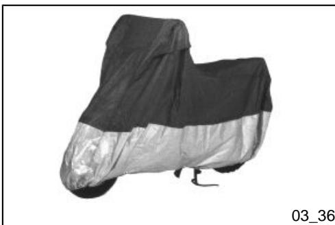
Periods of inactivity (03_36)
We recommend carrying out the following operations:
- Clean the scooter thoroughly and then cover it with a canvas;
- With engine off and piston at the bottom dead centre, remove the spark plug, fill with 1 ÷ 2 ~cm^3 of oil (adding more than this quantity is dangerous for the engine). Operate the starter button 1-2 times for roughly 1 second to turn the engine over slowly, then insert the spark plug again;
- Drain all the fuel from the scooter; spread antirust grease on the unpainted metal parts; keep the wheels lifted above the ground by resting the chassis on two wooden wedges;
- As regards the battery, follow the instructions in the «Battery» section.
Recommended products
AGIP CITY HI TEC 4T
Oil to lubricate flexible transmissions (throttle control) Oil for 4-stroke engines
Cleaning the vehicle
In order to soften the dirt and mud deposited on the painted surfaces, use a low pressure jet of water. Once softened, mud and dirt must be removed with a soft sponge for bodywork soaked in lots of water and "shampoo" (2-4% of car shampoo in water). Then rinse abundantly with water, and dry with a shammy cloth. For the outside of the engine, use petroleum, a brush and clean cloths. Petroleum can damage paintwork. Remember that any polishing with silicone wax must always be preceded by washing
CAUTION

DETERGENTS CAN POLLUTE WATER. THE VEHICLE MUST BE WASHED AT A WASH STATION EQUIPPED WITH A SPECIAL WATER PURIFICATION SYSTEM.
CAUTION

PER IL LAVAGGIO DEL MOTORE E DEL VEICOLO É SCONSIGLIATO L'UTILIZZO DELL'IDROPULITRICE; NEL CASO CHE NON SIA POSSIBLE EFFETTUARE TALE OPERAZIONE IN UN ALTRO MODO, É NECESSARIO:
USARE SOLAMENTE IL GETTO A VENTAGLIO.
- NON AVVICINARE LA LANCIA A MENO DI 2 FT (60 CM).
- NON USARE ACQUA A TEMPERATURE SUPERIORI A 100^ F (40^)
- NON UTILIZZARE IL GETTO AD ALTA PRESSIONE.
- NON UTILIZZARE IL LAVAGGIO A VAPORE.
- NON INDIRIZZARE IL GETTO DIRETTAMENTE VERSO: IL MOTORE, I CABLAGGI ELETTRICI, LE FERITOIE DI RAFFREDDAMENTO DEL COPERCHIO TRASMISSIONE E DEL COPERCHIO CHIOCCIOLA.
CAUTION

NEVER WASH THE SCOOTER IN DIRECT SUNLIGHT, ESPECIALLY IN SUMMER WHEN THE BODYWORK IS STILL HOT AS THE SHAMPOO COULD DAMAGE THE PAINTWORK IF IT DRIES BEFORE BEING RINSED OFF. NEVER USE CLOths SOAKED IN ALCOHOL, PETROL, DIESEL OIL OR KEROSENE FOR CLEANING THE PAINTED OR PLASTIC SURFACES, IN ORDER NOT TO DAMAGE THE LUSTRE FINISH OR ALTER THE MECHANICAL PROPERTIES. USING SILICONE-BASED WAX CAN DAMAGE THE PAINTED SURFACES, DEPENDING ON THE VEHICLE COLOUR (SATIN COLOURS). FOR FURTHER INFORMATION ON THIS MATTER, CONTACT AN AUTHORISED SERVICE CENTRE.
STARTING FAILURE
| Emergency switch in «OFF» | Set the switch back to «ON» |
| Fuse blown | Replace the blown fuse and have the vehicle checked by an Authorised Service Centre. |
STARTING DIFFICULTIES (SEE «START-UP PROBLEMS» SECTION)
| Lack of fuel in tank. | Refuelling |
| Injection system fault | Contact an Authorised Service Centre |
| Faulty fuel pump | Contact an Authorised Service Centre |
| Battery flat | Recharge the battery. |
- IMPORTANT: DO NOT USE THE SCOOTER TO THE COMPLETE EXHAUSTION OF FUEL; SHOULD THIS OCCUR, DO NOT ATTEMPT TO START THE ENGINE. TURN THE KEY SWITCH TO «OFF» AND TOP-UP THE FUEL TANK AS SOON AS POSSIBLE. FAILURE TO FOLLOW THESE GUIDELINES COULD DAMAGE THE FUEL PUMP AND/OR THE CATALYTIC CONVERTER.
IGNITION PROBLEMS
| Faulty spark plug | Contact an Authorised Service Centre. |
| Faulty ignition / injection control unit. Due to the presence of high voltage, this check should only be carried out by an expert. | Contact an Authorised Service Centre |
LACK OF COMPRESSION
| Loose spark plug. | Screw in the spark plug tightly |
| Cylinder head loose, piston gas rings worn. | Contact an Authorised Service Centre. |
| Valve stuck | Contact an Authorised Service Centre. |
Clogged or dirty air filter
Try to blow out with compressed
air, otherwise replace the filter
INSUFFICIENT BRAKING
Greasy disc. Worn pads. Faulty braking system. Presence of air in the front and rear brake circuit.
Contact an Authorised Service
Centre.
INEFFICIENT SUSPENSIONS
Shock absorber fault, oil leak, end buffer damaged; shock absorber preloading incorrectly set
Contact an Authorised Service
Centre.
IRREGULAR AUTOMATIC TRANSMISSION
Variator rollers and/or driving belt damaged
Contact an Authorised Service
Centre.
X8 400 i.e.

PIAGGIO

Chap. 04
Technical data
ENGINE TECHNICAL DATA
| Version (400) | 400 |
| Engine | Single-cylinder, four-stroke, four valves, single overhead camshaft, chain driven on the flywheel side |
| Cubic capacity | 399 cm³ |
| Bore x stroke | 85.8 X 69 mm |
| Compression ratio | 10.6 ± 0.5 : 1 |
| Idle speed | 1500 ± 100 rpm |
| Maximum torque (to the crankshaft) | 36 Nm at 5500 rpm |
| Maximum power (to the crankshaft) | 24.5 kW at 7250 rpm |
| Electronic ignition | inductive, high efficiency integrated with the injection system, with variable timing and separate HV coil. |
| Ignition advance (before TDC) | Variable advance controlled by the injection control unit |
| Fuel supply | 38 Ø mm throttle body and single injector |
| Lubrication | Engine lubrication with trochoidal pump (inside the crankcase), oil filter and pressure adjustment by-pass. |
| Cooling | Forced fluid circulation, with engine driven pump; 3-way thermostat to pump intake. |
| Transmission | Automatic expandable pulley speed variator, V belt, dry self-ventilating automatic centrifugal clutch, gear reduction unit and transmission casing with forced air circulation cooling. |
| Spark plug | • NGK CR7EKB
• Champion RG6YC |
| Valve clearance | intake: 0.15 mm discharge (when cold): 0.15 mm (when cold) |
| Exhaust muffler | absorption-type exhaust muffler with catalytic converter. |
| Engine oil (empty) | 1.7 lt. |
| Engine oil (at oil and filter change) | 1.5 lt. |
| Rear hub oil | 250 cc |
VEHICLE TECHNICAL DATA
| Overall width | 750 mm |
| Overall length | 2190 mm |
| Overall height | 1360 mm |
| Saddle height | 790 mm |
| Wheelbase | 1540 mm |
| Front suspension | Double effect hydraulic telescopic fork with Ø 35 mm stems and pin backwards with connections for double brake calliper |
| Rear suspension | Engine with swinging fork attached to the frame by means of an arm with one degree of freedom and a pair of double effect hydraulic shock absorbers with 4 adjustable preload positions. |
| Front brake | Ø 240mm double disk brake with hydraulic control activated by the handlebar right-hand lever. |
| Rear brake | Ø 240 mm disc brake with hydraulic control activated by handlebar left lever. |
| Front wheel rim | Die-cast aluminium alloy, 3.50"x14" |
| Rear wheel rim | Die-cast aluminium alloy 4.50"x14" |
| Front tyre | Tubeless 120/70 - 14" - Michelin Gold Standard M/C 55S |
| Rear tyre | Tubeless 140/70 - 14" - Michelin Gold Standard M/C 68S |
| Frame | Welded tubular steel structure, with asymmetrical frame structure, front beams and union elements in stamped sheets. |
| Kerb weight | 206 kg |
| Maximum load | 180 kg. |
| Cooling system | Capacity: approx. 1.8 litres |
| Fuel tank capacity | Tank capacity: ~12 l (approximate value) |
| Fuel reserve | approx. 2.5 litres (indicative value) |
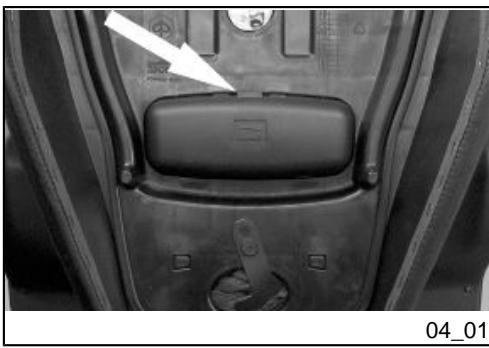
Kit equipment (04_01)
The tools are located under the seat in an appropriate container. To open, release the catch.
Tools: One 16 mm socket wrench; one twin screwdriver, one wrench for the shock absorbers.
X8 400 i.e.

PIAGGIO

Chap. 05
Spare parts and accessories
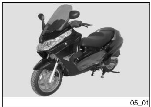
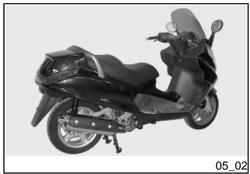
Warnings (05_01, 05_02)
WARNING

TO PREVENT ACCIDENTS AND TO GUARANTEE PROPER STABILITY, PERFORMANCE AND SAFETY, RIDE THE VEHICLE VERY CAREFULLY WHEN IT IS Fitted WITH ACCESSORIES OR WITH UNUSUAL LOADS.
WARNING

IT IS ALSO RECOMMENDED THAT "ORIGINAL PIAGGIO SPARE PARTS" BE USED, AS THESE ARE THE ONLY ONES OFFERING YOU THE SAME QUALITY GUARANTEE AS THOSE INITIALLY FITTED ON THE SCOOTER. THE USE OF NON-ORIGINAL SPARE PARTS RENDERS THE WARRANTY Void.
WARNING

PIAGGIO MARKETS ITS OWN LINE OF ACCESSORIES THAT ARE RECOGNISED AND GUARANTEED FOR USE. IT IS THEREFORE ESSENTIAL, IN ORDER TO CHOOSE AND MOUNT THE ACCESSORIES CORRECTLY, TO CONTACT AN AUTHORISED DEALER OR SERVICE CENTRE. THE USE OF NON-ORIGINAL ACCESSORIES MAY AFFECT THE STABILITY AND OPERATION OF YOUR VEHICLE AND REDUCE SAFETY LEVELS WITH POTENTIAL RISKS FOR THE RIDER.

NEVER RIDE THE SCOOTER FITTED WITH ACCESSORIES (GLOVE-BOX) AT SPEEDS OVER 110 KM/H.
THE SCOOTER CAN BE RIDEN AT A HIGHER SPEED WITHOUT THE AFORE-MENTIONED ACCESSORIES WITHIN THE LIMITS ESTABLISHED BY LAW.
IF THERE SHOULD BE NON-PIAGGO ACCESSORIES INSTALLED, OR AN AB-NORMAL LOAD, OR IF THE SCOOTER IS NOT IN A GENEALLY GOOD CONDITION, OR WHENEVER WEATHER CONDITIONS DEMAND IT, SPEED SHOULD BE REDUCED FURTHER.
WARNING

BE EXTREMELY CAREFUL WHEN INSTALLING AND REMOivating THE MECHANICAL ANTI-THEFT DEVICE ON THE VEHICLE (U-SHAPED PADLOCK, DISK BLOCK, ETC.).
MAINLY NEAR THE BRAKE PIPES, TRANSMISSIONS AND/OR ELECTRIC CABLES, AN INCORRECT INSTALLATION OR REMOVAL OF THE ANTI-THEFT DEVICE AS WELL AS LEAVING IT ON BEFORE STARTING THE VEHICLE CAN SERIOUSLY DAMAGE ITS COMPONENTS, COMPROMISE THE CORRECT FUNCTIONING OF THE VEHICLE AND USERS' SAFETY.
X8 400 i.e.

PIAGGIO

Chap. 06 Programmed maintenance
Scheduled maintenance table
Adequate maintenance is fundamental to ensuring long-lasting, optimum operation and performance of your scooter.
For this purpose, PIAGGIO has developed a series of checks and maintenance operations (against payment) that are contained in the summary table shown on the next page. Any minor faults should be reported without delay to a PIAGGIO Dealer or Authorised Service Centre without waiting until the next scheduled service.
Carrying out scheduled services on time is necessary to ensure your warranty remains valid. For all other information concerning Warranty procedures and "Scheduled Maintenance", please refer to the "Warranty Booklet".
EVERY 2 YEARS
| Coolant - change |
| Brake fluid - change |
AFTER 1,000 KM
| Safety locks - check |
| Throttle lever - adjustment |
| Engine oil - change |
| Electrical system and battery - check |
| Coolant level - check |
| Brake fluid level - check |
| Engine oil - replacement |
| Brake pads - check condition and wear |
| Tyre pressure and wear - check |
| Vehicle and brake test - road test |
| Hub oil - change |
| Crankcase breather - empty |
| Steering - adjustment |
| Injection system pipework - visual check |
AFTER 10,000 KM AFTER 30,000 KM AFTER 50,000 KM AND AFTER 70,000 KM
| Safety locks - check |
| Spark plug - replacement |
| Driving belt - replacement |
| Throttle lever - adjustment |
| Air filter - check |
| Air filter belt compartment - check |
| Engine oil - change |
| Electrical system and battery - check |
| Coolant level - check |
| Brake fluid level - check |
| Engine oil - replacement |
| Brake pads - check condition and wear |
| Sliding block / variable speed rollers - change |
| Tyre pressure and wear - check |
| Vehicle and brake test - road test |
| Hub oil - check |
| Idle speed (*) - adjustment |
| Centre/side stand joint - lubrication |
| Suspensions - check |
| Steering - Check |
| Injection system pipework - visual check |
| Crankcase breather - empty |
AFTER 20,000 KM AFTER 40,000 KM AFTER 60,000 KM AND AFTER 80,000 KM
| Safety locks - check |
| Bushing of driven pulley |
| Spark plug - replacement |
| Driving belt - replacement |
| Throttle lever - adjustment |
| Air filter - check |
| Air filter belt compartment - check |
| Engine oil - change |
| Valve clearance - check |
| Electrical system and battery - check |
| Coolant level - check |
| Brake fluid level - check |
| Engine oil - replacement |
| Brake pads - check condition and wear |
| Sliding block / variable speed rollers - change |
| Tyre pressure and wear - check |
| Vehicle and brake test - road test |
| Hub oil - check |
| Idle speed (*) - adjustment |
| Centre/side stand joint - lubrication |
| Crankcase breather - empty |
| Suspensions - check |
| Steering - Check |
| Injection system pipework - visual check |
| Fuel filter - check |
(*) See instructions in «Idle speed adjustment» section
RECOMMENDED PRODUCTS TABLE
| Product | Description | Specifications |
| AGIP ROTRA 80W-90 | Rear hub oil | SAE 80W/90 Oil that exceeds the requirements of API GL3 specifications |
| AGIP CITY HI TEC 4T | Oil to lubricate flexible transmissions (throttle control) | Oil for 4-stroke engines |
| AGIP FILTER OIL | Oil for air filter sponge | Mineral oil with specific additives for increased adhesiveness |
| AGIP GP 330 | Calcium complex soap-based grease with NLGI 2; ISO-L-XBCIB2 | Grease (brake control levers, throttle grip) |
| AGIP CITY HI TEC 4T | Engine oil | SAE 5W-40, API SL, ACEA A3, JASO MA Synthetic oil |
| AGIP BRAKE 4 | Brake fluid | FMVSS DOT 4 Synthetic fluid |
| AGIP PERMANENT SPEZIAL | coolant | Monoethylene glycol-based antifreeze fluid, CUNA NC 956-16 |
TABLE OF CONTENTS
A
Air filter: 52
F
Fuses: 59
M
Maintenance: 43, 89, 90
Mirrors: 71
B
Battery: 57
Brake: 55, 71
H
Headlight: 67
Horn: 12
Hub oil: 47
C
Clock: 10
1
Identification: 23
Immobilizer: 13, 16
Instrument panel: 9
D
Disc brake: 71
K
Key switch: 10
Keys: 14
E
Engine oil: 44-46
Engine stop: 13
L
Light switch: 12
s
Saddle: 18, 20-22
Scheduled maintenance: 90
Shock absorbers: 31
Spark plug: 51
Stand: 37
Start-up: 13
T
Technical Data: 79
Top box: 24
Transmission: 38
Turn indicators: 69
Tyre pressure: 30
Tyres: 49

PIAGGIO
The descriptions and illustrations given in this publication are not binding. While the basic specifications as described and illustrated in this manual remain unchanged, PIAGGIO-GILERA reserves the right, at any time and without being required to update this publication beforehand, to make any changes to components, parts or accessories, which it considers necessary to improve the product or which are required for manufacturing or construction reasons.
Not all versions/models shown in this publication are available in all countries. The availability of single versions should be checked at the official Piaggio sales network.
Copyright 2007 - PIAGGIO & C. S.p.A. Pontedera. All rights reserved. Reproduction of this publication in whole or in part is prohibited."
PIAGGIO & C. S.p.A. - After-Sales
V.Ie Rinaldo Piaggio, 23 - 56025 PONTEDERA (Pi)