
I-Tech HD 9000HD - Radio CROWN - Free user manual and instructions
Find the device manual for free I-Tech HD 9000HD CROWN in PDF.


| Product Type | Radio |
| Brand | Crown |
| Model | I-Tech HD 9000HD |
| Dimensions (approx.) | 200 x 100 x 50 mm |
| Weight (approx.) | 0.5 kg |
| Power Supply | AC 230V 50Hz |
| Battery Backup | Not applicable |
| Tuning Bands | AM, FM |
| Preset Stations | 20 (10 AM + 10 FM) |
| Display | LCD with backlight |
| Audio Output | Built-in speaker, headphone jack (3.5mm) |
| Antenna | Built-in ferrite bar (AM), telescopic (FM) |
| Controls | Rotary tuning, volume, buttons for functions |
| Additional Functions | Sleep timer, alarm clock |
| Material | Plastic cabinet |
| Color | Black |
| Cleaning Instructions | Wipe with a soft dry cloth |
| Safety Precautions | Do not expose to water or moisture |
| Spare Parts Availability | Contact Crown customer service |
| Repairability | Refer to qualified technician |
| User Manual | Available in PDF format |
Frequently Asked Questions - I-Tech HD 9000HD CROWN
User questions about I-Tech HD 9000HD CROWN
0 question about this device. Answer the ones you know or ask your own.
Ask a new question about this device
Download the instructions for your Radio in PDF format for free! Find your manual I-Tech HD 9000HD - CROWN and take your electronic device back in hand. On this page are published all the documents necessary for the use of your device. I-Tech HD 9000HD by CROWN.
USER MANUAL I-Tech HD 9000HD CROWN
natural_image
Front view of three I-TECH network equipment units (5000, 9000, 12000) with control knobs and drive dials, no visible text or symbols on the devices themselves.I-T5000 HD
I-T9000 HD
I-T12000 HD
Obtaining Other Language Versions: To obtain information in another language about the use of this product, please contact your local Crown Distributor. If you need assistance, localing your local distributor, please contact Crown at 574-294-8000.
This manual does not include all of the details of design, production, or variations of the equipment. Nor does it cover every possible situation which may arise during installation, operation or maintenance.
The information provided in this manual was deemed accurate as of the publication date. However, updates to this information may have occurred. To obtain the latest version of this manual, please visit the Crown website at www.crownaudio.com.
Trademark Notice: Crown, Crown Audio, IQ, BCA, and Amcron are registered trademarks of Crown International. HiQnet is a trademark of Harman International Industries, Inc. Other trademarks are the property of their respective owners.
Some models may be exported under the name Amcron.*
©2006 by Crown Audio ^® Inc., 1718 W. Mishawaka Rd., Elkhart, Indiana 46517-9439 U.S.A. Telephone: 574-294-8000
140811-1
5/11
Important Safety Instructions
- Read these instructions.
- Keep these instructions.
- Heed all warnings
- Follow all instructions.
- Do not use this apparatus near water.
- Clean only with a dry cloth
- Do not block any ventilation openings. Install in accordance with the manufacturer's instructions.
-
Do not install near any heat sources such as radiators, heat registers, sloves, or other apparatus (including amplifiers) that produce heat.
-
Do not defeat the safety purpose of the polarized or grounding-type plug. A polarized plug has two blades with one wider than the other. A grounding-type plug has two blades and a third grounding prong. The wide blade or the third prong is provided for your safety. If the provided plug does not fill into your outlet, consult an electrician for replacement of the obsolete outlet.
-
Proiect the power cord from being walked on or pinched, particularly at plugs, convenience receptacles, and the point where they exit from the apparatus.
-
Only use attachments/accessories specified by the manufacturer.
-
Use only with a cart, stand, tripod, bracket, or table specified by the manufacturer, or sold with the apparatus. When a cart is used, use caution when moving the carl/apparatus combination to avoid injury from tip-over.
-
Unplug this apparatus during lightning storms or when unused for long periods of time.
-
Refer all servicing to qualified service personnel. Servicing is required when the apparatus has been damaged in any way, such as power-supply cord or plug is damaged, liquid has been spilled or objects have fallen into the apparatus, the apparatus has been exposed to rain or moisture, does not operate nor mally, or has been dropped.
-
Use the mains plug to disconnect the apparatus from the mains.
-
WARNING: TO REDUCE THE RISK OF FIRE OR ELECTRIC SHOCK, DO NOT EXPOSE THIS APPARATUS TO RAIN OR MOISTURE.
-
DO NOT EXPOSE THIS EQUIPMENT TO DRIPPING OR SPLASHING AND ENSURE THAT NO OBJECTS FILLED WITH LIQUIDS, SUCH AS VASES, ARE PLACED ON THE EQUIPMENT.
-
THE MAINS PLUG OF THE POWER SUPPLY CORD SHALL REMAIN READILY OPERABLE.
TO PREVENT ELECTRIC SHOCK DO NOT REMOVE TOP OR BOTTOM COVERS. NO USER SERVICEABLE PARTS INSIDE. REFER SERVICING TO QUALIFIED SERVICE PERSONNEL.
À PRÉVENIR LE CHOC ÉLECTRIQUE N'ENLEVEZ PAS LES COUVERCLES. IL N'Y A PAS DES PARTIES SERVICEABLE À L'INTÉRIEUR. TOUS REPARATIONS DOIT ETRE FAIRE PAR PERSONNEL QUALIFIÉ SEULMENT.
PARA PREVENIR UN CHOQUE ELÉCTRICO. NO RETIRE LAS CUBIERTAS SUPERIOR O INFERIOR. NO EXISTEN PARTES QUE PUEDÁN SER REPARADAS POR EL USUARIO AL INTE RIOR. REMITA EL SERVICICO AL PERSONAL TÉCHNICAL CALIFICADO.
TO COMPLETELY DISCONNECT THIS EQUIPMENT FROM THE AC MAINS, DISCONNECT THE POWER SUPPLY CORD PLUG FROM THE AC RECEPTACLE. THE MAINS PLUG OF THE POWER SUPPLY CORD SHALL REMAIN READILY OPERABLE.
POUR DÉMONTER COMPLÈTEMENT L'ÉQUIPEMENT DE L'ALIMENTATION GÉNÉRALE, DÉMONTER LE CÂBLE D'ALIMENTATION DE SON RÉCEPTACLE. LA PRISE D'ALIMENTATION RESTERA AISÉMENT FONCTIONNELLE.
WATCH FOR THESE SYMBOLS:
The lightning bolt triangle is used to alert the user to the risk of electric shock.
The exclamation point triangle is used to alert the user to important operating or maintenance instructions.
REGARDEZ CES SYMBOLES:
The I-Tech Series amplifiers are certified only at 120V ∼ in Canada.
IMPORTANT
CAUTION! Do not locate sensitive high-gain equipment such as pre-amplifiers directly above or below the unit. Because this amplifier has a high power density, it has a strong magnetic field which can induce hum into unshielded devices that are located nearby. The field is strongest just above and below the unit.
If an equipment rack is used, we recommend locating the amplifiers) in the bottom of the rack and the preamplifier or other sensitive equipment at the top.
FCC COMPLIANCE NOTICE
This device complies with part 15 of the FCC rules. Operation is subject to the following two conditions: (1) This device may not cause harmful interference, and (2) this device must accept any interference received, including interference that may cause undesired operation.
CAUTION: Changes or modifications not expressly approved by the party responsible for compliance could void the user's authority to operate the equipment.
NOTE: This equipment has been tested and found to comply with the limits for a Class B digital device, pursuant to part 15 of the FCC Rules. These limits are designed to provide reasonable protection against harmful interference in a residential installation. This equipment generates, uses, and can radiate radio frequency energy and, if not installed and used in accordance with the instruction manual, may cause harmful interference to radio communications. However, there is no guarantee that interference will not occur in a particular installation. If this equipment does cause harmful interference to radio or television reception, which can be determined by turning the equipment off and on, the user is encouraged to try to correct the interference by one or more of the following measures:
• Reorient or relocate the receiving antenna.
- Increase the separation between the equipment and receiver.
- Connect the equipment into an outlet on a circuit different from that to which the receiver is connected.
- Consult the dealer or an experienced radio/TV technician for help.


| Crown International, Inc. | DECLARATION of CONFORMITY | |
| ISSUED BY: Crown International, Inc.1718 W. Mishawaka RoadElkhart, Indiana 46517 U.S.A. | FOR COMPLIANCE QUESTIONS ONLY: | Sue Whitfield574-294-8289 |
| European Representative's Name and Address:David Budge10 Harvest CloseYaleley GU46 6YSUnited KingdomEquipment Type: Commercial Audio Power AmplifiersFamily Name: I-Tech HDModel Names: I-T5000HD, I-T9000HD, I-T12000HDEMC Standards:EN 55103-1:1997 Electromagnetic Compatibility - Product Family Standard for Audio, Video, Audio-Visual and Entertainment Lighting Control Apparatus for Professional Use, Part 1: EmissionsEN 55103-1:1997 Magnetic Field Emissions-Annex A @ 10 cm and 20 cmEN 61000-3-2:2005 and AMD1:2008 Limits for Harmonic Current Emissions (equipment input current less than or equal to 16 A per phase)EN 61000-3-3:2008 Limitation of Voltage Fluctuations and Flicker in Low-Voltage Supply Systems Rated Current less than or equal to16AEN 55022:2006 Limits and Methods of Measurement of Radio Disturbance Characteristics of ITE: Radiated, Class B Limits; Conducted, Class AEN 55103-2:1997 Electromagnetic Compatibility - Product Family Standard for Audio, Video, Audio-Visual and Entertainment Lighting Control Apparatus for Professional Use, Part 2: ImmunityEN 61000-4-2:2001 Electrostatic Discharge Immunity (Environment E2-Criteria B, 4k V Contact, 8k V Air Discharge)EN 61000-4-3:2006 Radiated, Radio-Frequency, Electromagnetic Immunity (Environment E2, criteria A)EN 61000-4-4:2007 Electrical Fast Transient/Burst Immunity (Criteria B)EN 61000-4-5:2006 Surge Immunity (Criteria B)EN 61000-4-6:2006 Immunity to Conducted Disturbances Induced by Radio-Frequency Fields (Criteria A)EN 61000-4-11:2004 Voltage Dips, Short Interruptions and Voltage VariationSafety Standard:IEC 60065: 2001 7th Ed. and AMD 1: 2005 Safety Requirements - Audio Vidoo and Similar Electronic ApparatusI certify that the product identified above conforms to the requirements of the EMC Council Directive 89/336/EEC as amended by 92/31/EEC, and the Low Voltage Directive 73/23/EEC as amended by 93/68/EEC. | ||
| Signed | Andrew StoppAndrew StumpTitle: Director of Manufacturing | Date of Issue: November 1, 2008 |
Table of Contents
Important Safety Instructions 2
Declaration of Conformity....3
Table of Contents 4
1 Welcome ....5
1.1 Features 5
1.2 How to Use This Manual 5
2 Setup 6
2.1 Unpack and Install Your Amplifier 6
2.2 Connecting to AC Mains 7
2.3 Wire Inputs and Outputs 7
3 Operation 11
3.1 Protecting Your Speakers....11
3.2 Startup Procedure 11
3.3 Precautions 11
3.4 Front Panel Controls and Indicators 12
3.5 Back Panel Controls, Indicators and Connectors .... 13
4 Advanced Operation ....14
4.1 Advanced Operation Table of Contents....14
4.2 Navigating the LCD Control Screen....15
4.3 Presels 23
4.4 File Transfer Via the USB Port....24
4.5 List of Pop-Up Boxes and Descriptions....25
4.6 Digital Audio Options (AES/EBU) 26
4.7 Networking the Amplifier....26
4.8 Software-Controllable Onboard DSP 26
5 Troubleshooting....39
6 Specifications ....41
7 AC Power Draw and Thermal Dissipation....45
8 Advanced Features ....48
8.1 Protection Systems 48
8.2 Global, Switching Power Supply with PFC 48
8.3 3rd Generation Class I Circuitry 48
8.4.Color-Coded Rear Overlay 498
9 Appendix A: Network and CobraNet Basics....49
Appendix B: Setting Sensitivity for Best Gain Staging.....53
10 Service....54
11 Warranty....55
Product Registration....57
Crown Factory Service Information Form 59
I-T5000HD
| 20 Hz - 20 kHzPower |
| 2-ohm Dual (per ch.) | 1,800W |
| 4-ohm Dual (per ch.) | 2,000W |
| 8-ohm Dual (per ch.) | 1,250W |
| 4-ohm Bridge | 3,600W |
| 8-ohm Bridge | 4,000W |
20 Hz - 20 kHz Power refers to guaranteed minimum power in watts with 0.35% THD.
I-T9000HD
| 20 Hz - 20 kHzPower |
| 2-ohm Dual (per ch.) | 2,500W |
| 4-ohm Dual (per ch.) | 3,000W |
| 8-ohm Dual (per ch.) | 1,500W |
| 4-ohm Bridge | 5,000W |
| 8-ohm Bridge | 6,000W |
20 Hz - 20 kHz Power refers to guaranteed minimum power in watts with 0.35% THD.
I-T12000HD
| 20 Hz - 20 kHz |
| Power |
| 2-ohm Dual (per ch.) | 3,500W |
| 4-ohm Dual (per ch.) | 4,000W |
| 8-ohm Dual (per ch.) | 2,100W |
| 4-ohm Bridge | 7,000W |
| 8-ohm Bridge | 8,000W |
20 Hz - 20 kHz Power refers to guaranteed minimum power in watts with 0.35% THD.

1 Welcome
The Crown® I-TechHD Series offers amazing power, light weight and ease of use for touring sound applications. Unlike other amplifiers, it includes onboard high-definition DSP, an LCD control screen, and a built-in network connection.
Modern power amplifiers are sophisticated pieces of engineering capable of producing extremely high power levels. They must be treated with respect and correctly installed if they are to provide the many years of reliable service for which they were designed.
In addition, I-Tech Series amplifiers include a number of features which require some explanation before they can be used to their maximum advantage.
Please take the time to study this manual so that you can obtain the best possible service from your amplifier.
1.1 Features
- Global Power Supply with PFC (Power Factor Correction) works anywhere in the world.
• High power density, up to 8000 watts in a 2U chassis. - Highest output voltage in the industry (200V peak) provides clean transient peaks.
-
3rd-generation patented Class I (BCA ^® ) circuitry couples power efficiently to the load and provides low AC current draw.
-
Onboard high-definition DSP with 24-bit, 192 kHz Cirrus Logic SHARC A/D and D/A converters. Advanced IIR filters and linear-phase FIR filters.
- Pushbutton presets simplify setup. Custom presets for various loudspeakers can be downloaded.
• AES/EBU digital audio input - EtherCon® Ethernet connector for HiQnet™ control or CobraNet digital audio transport. This "Single Plug" connection allows HiQnet protocol and CobraNet digital audio through the same CAT 5 cable.
• Analog and digital thru connectors. - LCD Control Screen is used to adjust the amplifier's attenuation and muting, configure the amp, set up and view error monitoring, and recall DSP presets to reconfigure the amp for various applications.
- Comprehensive array of indicators provide accurate diagnostics: Power, Data, along with Ready. Signal. Clip, Thermal and Fault for each channel.
- AC mains indicator in power switch glows green when AC power is present.
-
Front-panel USB connector accepts a USB drive to transfer presets from the drive to the amplifier DSP, and vice versa.
-
Light weight due to aluminum chassis, special internal construction and switching power supply.
• Thermal management controller and two discrete thermal zones with variable-speed fans, forced-air cooling. - Advanced protection circuitry guards against shorted outputs, DC, mismatched loads, general overheating, under/over voltage, high-frequency overloads and internal faults.
- Three-Year, No-Fault, Fully Transferable Warranty completely protects your investment and guarantees its specifications.
1.2 How to Use This Manual
This manual provides you with the necessary information to satisfy and correctly setup and operate your amplifier. It does not cover every aspect of installation, setup or operation that might occur under every condition. For additional information, please consult the online help in System Architised software, Crown's Amplifier Application Guide, J-Tech Application Guide (available online at www.crownaudio.com), Crown Technical Support, your system installer or retailer.
We strongly recommend you read all instructions, warnings and cautions contained in this manual. Also, for your protection, please send in your warranty registration card today. And save your bill of sale — it's your official proof of purchase.
2 Setup

2.1 Unpack and Install Your Amplifier
Please unpack and inspect your amplifier for any damage that may have occurred during transit. If damage is found, notify the transportation company immediately. Only you can initiate a claim for shipping damage. Crown will be happy to help as needed. Save the shipping carton as evidence of damage for the shipper's inspection.
We also recommend that you save all packing materials so you will have them if you ever need to transport the unit. Never ship the unit without the factory pack.
YOU WILL NEED (not supplied):
- Input wiring cables
• Output wiring cables - Ethernet cables
- Rack for mounting amplifier (or a stable surface for stacking)

WARNING: Before you start to set up your amplifier, make sure you read and observe the Important Safety Instructions found at the beginning of this manual.

CAUTION: Before you begin, make sure your amplifier is disconnected from the power source, with the power switch in the "off" position and all level controls turned completely down (counterclockwise).
Use a standard 19-inch (48.3 cm) equipment rack (EIA RS-310B). See Figure 2.1 for amplifier dimensions.
You may also stack amps without using a cabinet.
NOTE: When transporting, amplifiers should be supported at both front and back.
MAGNETIC FIELD

CAUTION! Do not locate sensitive high-gain equipment such as preamplifiers or tape decks directly above or below the unit. Because this amplifier has a high power density, it has a strong magnetic field which can induce hum into unshielded devices that are located nearby. The field is strongest on the right side and right bottom of the amplifier (lacing the amplifier).
If an equipment rack is used, we recommend locating sensitive equipment at least 20 cm (8 inches) away from the amplifier.
When using an equipment rack, mount units directly on top of each other. Close any open spaces in rack with blank panels. DO NOT block front or rear air vents. The side walls of the rack should be a minimum of two inches (5.1 cm) away from the amplifier sides, and the back of the rack should be a minimum of four inches (10.2 cm) from the amplifier back panel.
Figure 2.2 illustrates standard amplifier airflow.

natural_image
3D technical illustration of a server rack with multiple drive bays and ventilation fans (no text or symbols)Figure 2.2 Airflow
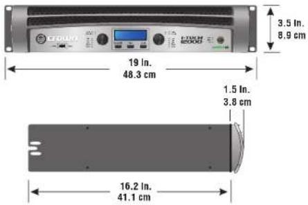
Figure 2.1
Dimensions
Operation Manual
2 Setup
2.2 Connecting to AC Mains
WARNING: The third (ground) prong of the supplied AC power cord connector is a required safety feature. Do not attempt to disable this ground connection by using an adapter or other methods.

Amplifiers don't create energy. The AC mains voltage and current must be sufficient to deliver the power you expect. You must operate your amplifier from an AC mains power source with not more than a 10% variation above or a 15% variation below the amplifier's specified line voltage range and within the specified frequency requirements (indicated on the amplifier's back panel label). If you are unsure of the output voltage of your AC mains, please consult your electrician.
Packed with your I-Tech amplifier is a clip that retains the power cord so it can't pull out accidentally.
- Locate the clip in a bag in the I-Tech packing carton.
- Locate the IEC power connector on the back of the amplifier. Above and below that connector are two slots. Stretch the ends of the clip and insert them into the slots (Figure 2.3).
- Plug the power cord all the way into the amplifier IEC power connector.
- Pull the clip to the left and snap it onto the power cord.

Figure 2.3 IEC Power Connector Clip
2.3 Wire Inputs and Outputs
2.3.1 Wiring basics
- Always use shielded wire for input wiring. The higher the density of the shield (the outer conductor) the better. Spiral wrapped shield is not recommended.
- When using unbalanced lines keep the cables as short as possible. Avoid lengths greater than 10 feet (3 meters).
- Do not run the audio input cables together with the high-level wiring such as loudspeaker wires or AC cords. (This lessens the chance of hum and noise being induced into the input cables.)
- Turn the entire sound system off before changing any connections. Crown is not liable for damage incurred when any transducer or component is overdriven.

THE CHANNEL 2 INPUT IS IGNORED by default in Bridge Mono mode. It can be summed using the input source selector and used instead of Channel 1.
For additional information on audio input wiring please refer to the Crown-Amplifier Application Guide available online at www.crownaudio.com. It contains helpful information on preventing unwanted subsonic frequencies, radio frequency interference, ground loops, and feedback oscillation.
When using network connections, pass the CAT 5 cable five times through a terrile core (Figure 2.4), available from Crown Audie Inc. This is to ensure compliance with emission regulations.
Figure 2.4 Pass the CAT 5 Cable Five Times Through the Ferrite Core

natural_image
3D diagram of a cube connected by a coiled cable, with a small labeled component on the left (no text or symbols present)2 Setup
2.3.2 Choose Input Wire and Connectors
Crown recommends using pre-built or professionally wired, balanced line (two-conductor plus shield), 22-24 gauge cables and connectors. Use 3-pin male XLR connectors.
Unbalanced line may also be used but may result in noise over long cable runs.
Figure 2.5 shows connector pin assignments for balanced analog wiring or AES/EBU digital wiring. The use of standard analog cable with AES/EBU will result in diminished performance. For best results, 110 ohm shielded twisted-pair cable for AES/EBU signals is highly recommenced. Figure 2.6 shows connector pin assignments for unbalanced analog wiring.
NOTE: Custom wiring should only be performed by qualified personnel.
2.3.3 Choose Output Wire and Connectors
Crown recommends using pre-built or professionally wired, high-quality, two- or four-conductor, heavy gauge speaker wire and connectors. Use Class 2 output wiring. You may use a 4-pole Spakon® connector (Figure 2.7) or banana plugs, spade lugs, or bare wire for your output connectors (Figure 2.8). To prevent the possibility of short circuits, wrap or otherwise insulate exposed loudspeaker cable connectors.
CAUTION – SHOCK HAZARD: Potentially lethal voltages exist at the output connectors when the amplifier is turned on and is passing a signal.
Using the guidelines below, select the appropriate size of wire based on the distance from amplifier to speaker.
Distance Wire Size
| up to 25 ft. | 16 AWG |
| 26-40 ft. | 14 AWG |
| 41-60 ft. | 12 AWG |
| 61-100 ft. | 10 AWG |
| 101-150 ft. | 8 AWG |
| 151-250 ft. | 6 AWG |
CAUTION: Never use shielded cable for output wiring.

Figure 2.5
Balanced Analog Input Connector Wiring or AES/EBU Digital Connector Wiring
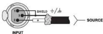
Figure 2.6 Unbalanced Analog Input Connector Wiring

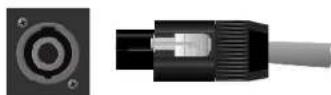
Figure 2.7
Left: Speakon ^16 Output Connector on Back Panel
Right: Speakon ^17 Cable Connector

Figure 2.8 Binding Post Connections
2 Setup
2.3.4 Stereo Mode Wiring
Typical input and output wiring is shown in Figure 2.9.
IMPORTANT: Turn off the amplifier and unplug its power cord.
INPUTS: Choose one of these options:
- Connect analog input wiring for both channels.
- Connect an AES/EBU digital signal to the AES/EBU connector.
OUTPUTS: Maintain proper polarity (+/-) on output connectors. Use Class 2 output wiring.
Figure 2.9 shows how to wire stereo speakers to the binding posts. Connect Channel 1 loudspeaker's positive (i) lead to Channel 1 positive (red) terminal of amp; repeat for negative (-). Repeat Channel 2 wiring as for Channel 1.
To wire stereo speakers to the Speakon® connectors, use one of these methods:
Method 1 (Table 1 and Figure 2.10): Wire one Speakon ^® cable connector to two speakers. Insert the Speakon ^® cable connector into the amplifier's top Speakon ^® connector.
Method 2 (Table 2 and Figure 2.11): Plug the Channel 1 speaker into the Channel 1 (top) Speakon ^® connector, and plug the Channel 2 speaker into the Channel 2 (bottom) Speakon ^® connector.
Table 1
Stereo Wiring Method 1: Use Top Speakon ^® Only
| PIN 1-1-2+2- | ||
| CH 1+1-2+2- |
Channel 1 Loudspasaker Enceinte du Canal 1 Lautsorecher Kansl 1 Altoparlante del Canal 1
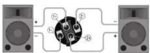

Channel 2
Loudspeaker
Enceinte du Canal 2
Lautsprecher Kansl 2
Altoparlante del Canal 2
Figure 2.10 Wiring Two Stereo Speakers to the Top Speakon® Connector
Operation Manual

Channel 2
Table 2 Stereo Wiring Method 2: Use Both Speakon's
Top
| PIN 1+1- | |
| CH 1↓1- |
Bottom
| PIN 1+1- | |
| CH 2+2- |
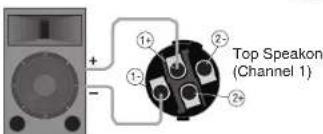
Channel 1 Loudspeaker
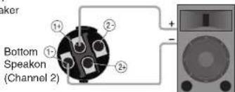
Channel 2
Loudspeaker
Figure 2.11 Stereo Wiring Using Both Speakori ^® Connectors
2 Setup
2.3.5 Bridge-Mono Mode
Overview: Turn on the amp, enable Bridge-Mono mode using the LCD Control Screen, turn off the amp, wire it, and turn it back on.
- Be sure that no cables are connected to the amplifier. Turn on the front-panel power switch. The LCD Control Screen will light up (Figure 2.12).
- Under the LCD Control Screen, press the Menu/Exit button. Press the Next button until you see OUTPUT MODE on the screen. If N/A is displayed, OUTPUT MODE is locked via software. If LOCKOUT is displayed, all the LCD screens are locked via software.
- Press an Encoder knob to select BRIDGE MONO. Press the knob again to confirm your choice. Press Menu/Exit. Turn down both level controls (Encoders) until you reach maximum attenuation.
4. IMPORTANT: Turn off the amplifier and unplug its power cord.
INPUTS: There are three ways to connect an input signal to the amplifier (Figure 2.13).
- Connect an analog signal source to the Channel-1 amplifier Input.
- Connect an AES/EBU digital signal source to the Digital Input IN connector.
NOTE: Crown provides a reference of wiring pin assignments for commonly used connector types in the Crown Amplifier Application Guide available at www.crownaudio.com.
OUTPUTS: Use Class 2 output wiring. There are two ways to wire the amplifier output connectors for Bridge-Mono mode:
1) Wire the speaker across the red binding post of each channel (Figure 2.14). Do not use the black binding posts when operating in Bridge-Mono mode.
2) Wire the speaker only to the top Speaker® connector as shown in Table 3 and Figure2.14

Figure 2.12
The LCD Control Screen
NOTE: In Bridge-Mono mode, the Channel 1 Level control sets the level; the Channel 2 Level control is defeated. All Channel-2 objects and controls are hidden and disabled.

Table 3 Top Speakor® Wiring for Bridge-Mono
| PIN 1+ 2+ | ||
| SPKR | + | - |

Figure 2.14 Wiring a Speaker in Bridge-Mono Mode to the Top Speaker ^® Connector
Operation Manual
3 Operation
3.1 Protecting Your Speakers
It's wise to avoid clipping the amplifier signal. Not only does clipping sound bad, it can damage high-frequency drivers. To prevent clipping, use System Architect software's Level Max suite to enable or display the peak voltage limiter and average power limiter in your amplifier's built-in DSP. That way, no matter how strong a signal your mixer produces, the amplifier output will not clip. Set the limiter threshold so that mixer signals above 0 dB or 0 VU on the mixer motors do not quite drive the amplifier into clipping.
Also, avoid sending strong subsonic signals to the amplifier. High-level, low-frequency signals from breath pops or dropped microphones can blow out drivers. To prevent subsonic signals, use one of these methods:
- Insert a highpass filter between mixer output and amplifier input (or between mixer and limiter).
- Use the I-Tech's onboard DSP to set up a highpass filters.
- Switch in highpass filters at your mixer. Set the filter to as high a frequency as possible that does not affect your program. For example, try 35 Hz for music and 75 Hz for speech. On each mixer input channel, set the filter frequency just below the lowest fundamental frequency of that channel's instrument.
3.2 Startup Procedure
When first turning on your amplifier, follow the procedures in the Quick-Start Guide on page 4 (stereo) or page 5 (bridge-mono).
If you ever need to make any wiring or installation changes, don't for get to disconnect the power cord.
For help with determining your system's optimum gain structure (signal levels) please refer to the Crown Amplifier Application Guide, available online at www.crownaudio.com.
3.3 Precautions
Your amplifier is protected from internal and external faults, but you should still take the following precautions for optimum performance and safety:
- Before use, your amplifier first must be configured for proper operation, including input and output wiring hookup. Improper wiring can result in serious operating difficulties. For information on wiring and configuration, please consult the Setup section of this manual or, for advanced setup techniques, consult Crown's Amplifier Application Guide available online at www.crownaucio.com.

- Use care when making connections, selecting signal sources and controlling the output level. The load you save may be your own!
- Do not short the ground lead of an output cable to the input signal ground. This may form a ground loop and cause oscillations.
- WARNING: Never connect the output to a power supply, battery or power main. Electrical shock may result.
- Tampering with the circuitry, or making unauthorized circuit changes may be hazardous and invalidates all agency listings.
- Do not operate the amplifier with the red Clip LEDs constantly flashing.
- Do not overdrive the mixer, which will cause clipped signal to be sent to the amplifier. Such signals will be reproduced with extreme accuracy, and loudspeaker damage may result
- Do not operate the amplifier with less than the rated load impedance. Due to the amplifier's output protection, such a configuration may result in premature clipping and speaker damage.
- CAUTION - SHOCK HAZARD: Potentially lethal voltages exist at the output connectors when the amplifier is turned on and is passing a signal.
Remember: Crown is not liable for damage that results from overdriving other system components.
3 Operation
3.4 Front Panel Controls and Indicators
Many of these functions can be disabled using Blackout Mode (a selection in the Advanced Menu, Section 4.2.3).
A. Cooling Vents
Front-to-rear forced airflow through foam dust tiller
B. LCD Control Screen
Integrated LCD with white backlight, controls amplifier setup and operation. The LCD Control Screen and its controls let the user adjust the amplifier's attenuation and muting, con figure the amp, set up and view error monitoring (such as temperature and load supervision), and recall DSP presets. The presets allow the user to quickly reconfigure the amp for various applications.
C. Power Switch
Push-on/push-off switch glows green when AC power is present at the power cord and the amplifier circuit breaker is in the "on" position.
D. USB 2.0 Connector
Accepts a USB drive to transfer presets from the drive to the amplifier DSP, and vice versa.
E. Fault Indicator
Red LED, one per channel, flashes when the amplifier output channel has stopped operating. Usually this means that the amplifier must be serviced.
F. Thermal Indicator
Red LED, one per channel, illuminates when the channel has shut down due to thermal stress or overload.
G. Clip Indicator
Rod LED, one per channel, illuminates when the channel's output signal reaches the onset of audible clipping. The Clip Indicator also will illuminate during Thermal Level Control (TLC) limiting. The Clip Indicator can be turned of during Blackout mode.
H. Level Controls (Encoders)
Speed-sensitive, 0.5 dB steps, range 0 to -100 dB. These two knobs affect the Channel-1 and Channel-2 output levels. They also select Menu items and adjust parameter values that are displayed on the LCD control screen.
1. Menu/Exit Button
"Menu" enters the main menu. "Exit" leaves the menu.
J. Prev Button
Selects the previous item in the menu.
K. Next Button
Selects the next item in the menu.
L. Signal Indicators
These can be disabled during Blackout mode. Three green LEDs per channel indicate the amplifier's input and output signal levels. From top to bottom the LEDs are
-10 dB: amplifier output is 10 dB below clipping.
-20 dB: amplifier output is 20 dB below clipping.
Signal: selected input signal is above -40 dBu.
M. Ready Indicator
Green LED, one per channel, illuminates when the channel is initialized and ready to produce audio output. Indicator is off when the channel is set to standby mode via System Architect or in Blackout mode.
N. Power Indicator
Blue LED indicates amplifier has been turned on and AC power is available. The LED will flash when the AC line voltage is 15% above or below the nominal rated range. This indicator can be turned off in Blackout mode.
0. Data Indicator
Yellow LED indicates network data activity. Data indicator flashes only when the amplifier is polled for data, or is polled to see whether it is online. This indicator can be turned off in Blackout mode.
P Bridge Mode Indicator
Yellow LED illuminates when the amplifier is set to Bridge-Mono mode.

Figure 3.1 Front Panel Controls and Indicators
3 Operation
3.5 Back Panel Controls, Indicators and Connectors
A. Fans
Provide front-to-back forced airflow for cooling.
ANALOG INPUTS SECTION
B. Balanced Analog XLR Inputs
A 3-pin female XLR connector for each channel.
C. Balanced Analog XLR Loop-Through Outputs
Two 3-pin male XLR output connectors are provided (one per channel). The signal at these connectors is paralleled with the input signal for leading the input signal to other amplifiers.
OUTPUTS SECTION
D. 4-Pole Speakon ^® Output Connectors
Two high-current, 50A Neutrik® Speakon® NL4MLP (mates with NL4FC and NL4), one per channel. Class 2 output wiring required.
These two connectors accept 2-pole or 4-pole Speakon® connectors. See Figures 2.5 through 2.10 and Tables 1, 2 and 3 for connector wiring. The top Speakon® connector is wired for both channels so it can be used for bridge mono wiring or for stereo wiring of two speakers to a single Speakon® connector.
E. Binding Post Output Jacks
One pair per channel of high-current, 60A color-coded binding posts. Accepts banana plugs, wire or spade lugs.
F. Power Cord Connector
Standard 20 amp IEC inlet. Voltage range is indicated above IEC inlet.
G. Reset Switch/Circuit Breaker
If the current draw of the amplifier exceeds sale limits, this breaker automatically disconnects the power supply from the AC mains. The switch resets the circuit breaker.
H. MAC Address
This specific amplifier's network identifier that is burned into its firmware.
1. Preset Indicator
LED flashes to signal the number of the current preset if active. LED is green if the preset values have not been changed once loaded. LED is yellow if the preset values have been changed since they were loaded.
J. Reset Button
To restore factory default settings: Press the Reset Button with a thin, non-conductive object, then turn on amplifier power, and continue to hold the reset button until the Preset light comes on green (approximately 16 seconds).
K. Data Indicator
Flashes yellow only when the amplifier is polled for data, or is polled to see whether it is online.
DIGITAL INPUTS SECTION
L. AES/EBU Digital Input
This 3-pin female XLR connector accepts a digital signal in the AES/EBU format.
M AES/EBU Digital Loop-through Output
Male XLR active/re-clocked AES/FBU digital loop-through. The signal at this connector duplicates the digital input signal for feeding the input signal to other amplifiers.
It is not recommended to loop through more than four amplifiers. If larger distribution of AES is needed, the use of an AES distribution amplifier is recommended.
NETWORKING SECTION
N. Link/Act Indicator
Shows network activity. The LINK ACT LED illuminates when the network port is connected and flashes when network activity is detected.
O. Network Connector
This EtherCon ^® Ethernet connector is for networking. Warning: Only connect to networks that remain inside the building.
P. Cond Indicator
Turns on if the amplifier is set to be the CobraNet conductor. The CobraNet conductor is a CobraNet node that provides the master timing clock for the CobraNet digital audio transport network.

Figure 3.2 Back Panel Controls and Connectors
4 Advanced Operation
4.1 Advanced Operation Table of Contents.....14
4.2 Navigating the LCD Control Screen ..... 15
4.2.1 Introduction 15
4.2.2 Basic Selections 16
4.2.3 Advanced Menu 17
4.2.4 Monitor Menu 20
4.2.5 Alert Menu....20
4.2.6 Networking Menu 21
4.2.7 CobraNet Menu 22
4.3 Presels....23
4.3.1 Introduction 23
4.3.2 User Presels 23
4.3.3 Downloadable Presets 23
4.4 File Transfer Via the USB Port 24
4.5 List of Pop-Up Boxes and Descriptions ..... 25
4.6 Digital Audio Options (AES/EBU) 26
4.7 Networking the Amplifier....26
4.7.1 NetworkTroubleshooter....26
4.8 Software-Controllable Onboard DSP 26
4.8.1 Amplifier DSP Selection Screen....27
4.8.2 Amplifier Mode 27
4.8.3 Levels and Indicators 27
4.8.4 Input Signal Router 28
4.8.5 Source Configuration 29
4.8.6 CobraNet Advanced Settings 29
4.8.7 Input Signal Compressor 30
4.8.8 Input Delay and Driver Delay 30
4.8.9 Input EQ and Output EQ 31
4.8.10 Crossover Filters 32
4.8.11 LevelMax Suite 33
4.8.12 Front Panel Security 33
4.8.13 Amplifier Settings 34
4.8.14 Amplifier Information 35
4.8.15 Apply to Others 35
4.8.16 Delay (Latency) 35
4.8.17 Preset Manager 36
4.8.18 Signal Generator 37
4.8.19 Fixed-Gain Mode in the I-Tech HD 38
4 Advanced Operation
4.2 Navigating the LCD Control Screen
4.2.1 Introduction
The LCD Control Screen and its controls let you configure the amplifier and access many features that before were available only through a remote computer. Also, you can recall DSP presets via the front panel. (Some DSP parameters cannot be adjusted with the LCD Control Screen. That is done in System Architect.)
Figure 4.1 shows the parts of the LCD Control Screen. Its functions are described below. NOTE: Listed functions can also be controlled in System Architect.

Figure 4.1 Parts of the LCD Control Screen
Here's how to access the various menus and settings in the LCD control screen:
- Starting from the Alternation screen, press Menu/Exit to go to the Sample Rate screen.
- Press Next to go to the next item in the menu.
- Press Prev to go to the previous item in the menu.
- Turn or press either Encoder knob to change the value of the displayodparameter.
- When you see a menu screen, push the knob once to see the items in that menu. Or press Next to go to the next menu.
- Press Menu/Exit to leave the menu and return to the Attenuation screen at any time.
Some menu items require confirmation: alter you request a change, the display might say "Press and hold." To confirm a change, press and hold an Encoder knob. If you don't want the change to occur during a confirmation, turn the knob or wait five seconds.
The entire front panel or just selected screens can be locked out or set to read only status using System Architect software. Locked-out screens will either say "Lockout" or the individual parameter will say "N/A". It a change is attempted the screen will say "Changes Disabled".
Operation Manual
MENU TREE
Attenuation - Mute - Lockout
Menu button
Sample Rate
Analog Input Sensitivity
Presets
Amp Mode
Locate
ALL MENUS: Next/Previous loops
Prev to Cobranet Menu

Menu Tree
As a handy reference, Figure 4.2 shows the menu structure of the LCD control screen. Starting from any Menu screen, press an Encoder knob to go to the first selection in the Menu. You can loop
through a menu's selections using the Next and
Prev buttons. The Menu/Exit button returns
you to the Attenuation screen which you see on power-up.
ADVANCED MENU Next
(press knob once to access these items:)
Attenuator Limits
Attenuator Link
Input Sources
Analog Source Select
Maximum Analog Input
Digital Source Select
AES Source Select
AES Input Trim
AES Input Status
Cobranet Source Select
Cobranet Input Trim
Bandpass Gain
Output Polarity
Input Delay
Speaker Delay
LED Meter Display Type
Bar Meter Display Type
LevelMax
Peak Voltage Limiter
RMS Voltage Limiter
Transducer Thermal Limiter
Pink Noise Generator
SLM (Sweep Load Monitoring)
Front Panel Blackout
MONITOR MENU
(press knob once to access these items:)
Load Monitoring
Thermal %
Thermal Temp deg. C
AC Line Voltage
Operating Time
Watts Output
Next
Exit
ALERT MENU
(press knob once to access these items:)
Amp Output Clip Errors
Analog Input Clip Errors
Thermal Errors
Low Limit Load Errors
High Limit Load Errors
SLM Errors
Line Voltage Errors
Fan Errors
Clear All Error Logs
Next
To Sample Rate
NETWORKING MENU
(press knob once to access
these items:)
Network Info
Manufacturing Info
HiQnet Node Address
DHCP
IP Address
Subnet Mask
Next
COBRANET MENU
(press knob once to access
these items:
Cobranet Information
Ch1 Cobranet Rx
Ch2 Cobranet Rx
Cobranet Tx
Cobranet Conductor Priority
Cobranet Transport Latency
Next
Sweep Load Monitoring is not available
in early I-Tech HD models.
Figure 4.2 The Menu Tree
4 Advanced Operation
Operation Examples
Operation Example 1
How to set the CH1 input sensitivity using the LCD Control Screen:
- After power-up, when the Attenuation screen appears, press
Menu/Exit.
2. Press Next
- Turn the left Encoder to set the sensitivity. NOTE: If you do not see the sensitivity you want, try changing the Maximum Analog Input level (see below).
4. Press Menu/Exit
Operation Example 2
How to set the Maximum Analog Input level using the LCD Control Screen:
- After power-up, when the Attenuation screen appears, press
Menu/Exit.
-
Press Next until you see "Advanced Menu."
-
Push an Encoder knob.
-
Press Next until you see "Maximum Analog Input."
-
Turn an Encoder to change the maximum analog input level
Press an Encoder to confirm and save your setting.
- Press Menu/Exit.
Operation Example 3
How to monitor the Thermal Errors using the LCD Control Screen:
- After power-up, when the Attenuation screen appears, press
Menu/Exit.
-
Press Prev until you see "Alert Menu."
-
Push an Encoder knob.
-
Press Next until you see "Thermal Errors."
Now let's look at the function of each menu selection.
4.2.2 Basic Selections
Opening Screen: On power-up, the LCD Control Screen displays the Crown logo. After a few seconds, the firmware version appears, then the Attenuation screen appears.
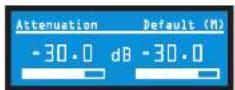
Attenuation and Bar Meters
This screen dis plays the attenuation in dB and on bar motors. To change the attenuation in either channel, turn the Encoder. Attenuation changes 0.5 dB per delent when you turn the Encoder slowly, and more when you turn the Encoder quickly. The current preset name is displayed in the upper-right corner. The (M) is explained on the next page under Presets.
Mute/Unmute (in the Attenuation screen)
- To mute either channel: Press and hold an Encoder knob for 1 second. The display will alternate between MUTE and the attenuation level. While the amplifier is muted, you can adjust attenuation for each channel by turning an Encoder knob.
- To unmute either channel: Press and hold an Encoder knob again for 1 second.

Front Panel Lockout (in the Attenuation screen)
The amplifier's administrator can control access to menu mode and the amplifier's attenuators. This lockout can be done either by the front panel buttons or by System Architect software.
To lock or unlock the menu with the front-panel buttons: press Next and Prev simultaneously. To lock or unlock the menu with System Architect software: go to the Tools Menu > Display Screen Security and press the lockout button. If a specific parameter is protected, the screen says "N/A" or "Change Disabled."
If the lockout is done from the software, the user can disable the lockout only in the software, not by pressing the front-panel but tons.
If the menu is locked and you press any button or turn an Encoder, the word "LOCKOUT" is displayed. If a specific parameter is protected, the screen says "N/A" or "Change Disabled."
4 Advanced Operation
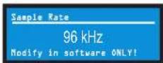
Sample Rate: Starting from the Attenuation screen, press Menu/Exit to go to the Sample Rate screen. The sample rate of the amplifier's DSP is displayed. It can be modified only in System Architect software because all of the FIR filter settings will need to be recalculated as a result of the change. Please refer to its Help files. When you route a Cobranet input, the sample rate displayed here must match the Cobranet source.
Analog Input Sensitivity: Turn the left Encoder knob to change the Ch. 1 Input sensitivity; turn the right Encoder knob to change the Ch. 2 Input sensitivity. This screen also displays the amp gain for each channel resulting from the sensitivity settings. See Figure 4.4.
Note: If you do not see the sensitivity you need, try changing the Maximum Analog Input level in the Advanced Menu (described later). This makes different sensitivities available.
To optimize the system gain structure, see Section 3.1 in the I-Tech application Guide at www.crownaudio.com/itoch/pdf/137327.pdf.

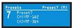
Presets: A preset is a group of DSP and amplifier settings for a particular speaker system. Turn an Encoder to view Presets 1 through 50. To recall a preset, press the Encoder, then press and hold the Encoder to confirm. For more information on presets, see Section 4.3.
The preset currently in use is displayed in the upper right corner.
(A) Active means that the amplifier is operating exactly according to that preset.
(M) Modified means that the amplifier is operating according to the preset but with some settings changed.
If a presel number is flashing, it is not in use.
In the example shown below.
- Preset 7 is in use (it's in the upper right corner).
- The amplifier settings have been modified (M) since Preset 7 was loaded.
- The large "7" is not flashing, which means that Preset 7 is in use.
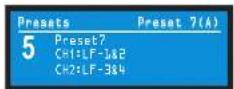
In the example shown below, you turned down an Encoder knob two notches after loading Preset 7.
- Preset 7 is in use (it's in the upper right corner).
- Preset 7 is active (A). That means the amplifier is operating exactly according to that preset.
- The large "5" is flashing because Preset 5 is not in use.
- Presel 5's Channel-1 label is "LF-1&2."
- Preset 5's Channel-2 label is *LF-3&4.
Amp Mode: This screen lets you set up the amplifier for Dual, Input Y or Bridge Mono mode. Turn an Encoder knob to choose among these three options, then press the knob to save your choice. You will be prompted to confirm your choice. The LCD screen displays the currently selected mode.
In Dual (or Stereo) mode, both channels operate independently. In Bridge Mono mode, both channels are summed to double the power, and the amplifier pulls out a mono signal. In Input Y mode, Channel 1's input signal feeds both channels, and each channel can be set to a different output level, usually for bi-amp operation.

Locate: Allows users to identify a specific amplifier in a large network of amplifiers without having to compare address information. Locate can be turned off from software and/or the front panel. Press an Encoder knob to turn on the Locate function. When on, the LCD screen flashes. Press the knob again to turn off the Locate function. In System Architect, the device icon has a blue outline to indicate that it is in Locate mode.

4.2.3 ADVANCED MENU
When you see this screen, press an Encoder knob to access the selections in the Advanced Menu, described next. To get to the Advanced Menu screen from the Attenuation screen, press Menu/Exit twice, then press Next five times.

4 Advanced Operation
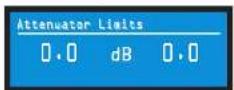
Attenuator Limits: You can set the maximum attenuation from 0 dB to -100 dB. This feature allows you to set a limit on the attenuators. Once set attenuation cannot be adjusted beyond this level. The attenuator limit appears as a line in the attenuator bar meter.
NOTE: The attenuator setting must be below the attenuator limit that you are trying to set. For example, if the attenuator is set at -3 dB, you cannot set the attenuator limit below -3 dB unless you decrease the attenuator level.
Attenuator Link You can set the attenuators to be independent or linked. Turn an Encoder knob to choose one of those options, then press the knob to save your choice.

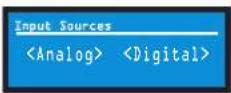
Input Sources: For each channel, turn the Encoder to select analog, digital, or automatic backup source. Options are:
Analog
Digital
Digital with analog backup
Digital with analog override
Digital with analog backup: The I-Tech HD is being fed a digital signal and an analog signal. The input is currently switched to the digital signal. If it fails, the I-Tech HD switches instantly to the analog signal.
Digital with analog override: The input is switched to the digital signal, and no analog signal is applied. If an analog signal is sent, the I-Tech HD switches instantly to the analog signal. If the analog signal fails, the I-Tech HD switches to the digital signal after a delay set by the Hold Time slider in the Input Section of the System Architect page.
Analog Source Select: Turn the left Encoder knob to select Analog 1, Analog 2, or Analog 1.2 signals for Channel 1. The right Encoder does the same for Channel 2. Press the knob to confirm your selection.
Analog 1 is Analog input Channel 1.
Anolog 2 is Analog input Channel 2.
Analog 1+2 is Analog input Channels 1 and 2.

Maximum Analog Input: Turn an Encoder to select the maximum input level to the amplifier: +21 dBu or +15 dBu. Press the knob to confirm your selection Note: Changing this value changes the range of sensitivities available to the amplifier.
For more information see Figure 4.4 and the I-Tech Sensitivity Charts in the Appendix of the I-Tech Application Guide. It is available online at www.crownaudio.com/itech/pdf/137327.pdf.

Digital Source Select: Turn the left Encoder knob to select the digital source for Channel 1: AES or Cobranet. The right Encoder does the same for Channel 2. Press the knob to confirm your choice.

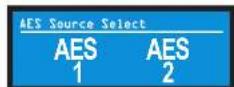
AES Source Select: Turn the left Encoder knob to select the digital source for Channel 1: AES1, AES2, or AES1.2. The right Encoder does the same for Channel 2. Press the knob to confirm your choice.
AES 1 Is AES Input Channel 1.
AES 2 is AES input Channel 2.
AES 1+2 is AES input Channels 1 and 2.
AES Input Trim: Turn the left Encoder knob to vary the gain of the AES digital signal for Channel 1: -100.0 dB to +20 dB. The right Encoder does the same for Channel 2. See Figure 4.4 for more information.

AES Input Status: "Lock" indicates that an AES cable is plugged in and the amplifier is receiving (and locking to) the AES clock pulse. "No Lock" means that the amplifier is not receiving, or is not locking to the AES clock pulse.

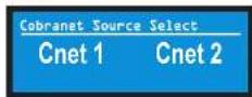
CobraNet Source Select: Turn the left Encoder knob to select the CobraNet source for Channel 1: Cnel1, Cnel2, or Cnel 1+2. The right Encoder does the same for Channel 2. Press the knob to confirm your choice.
Cnet1 is Bundle A.
Cnel2 is Bundle B.
Cnet 1:2 is Bundles A+B.
CobraNet Input Trim: Turn the left Encoder knob to vary the gain of the CobraNet digital signal for Channel 1: -100.0 dB to +20 dB. The right Encoder does the same for Channel 2. See Figure 4.4 for more information.

4 Advanced Operation
Bandpass Gain: In each channel of the I-Tech HD's DSP, just before the output limiter and after the preceding filter, is a gain block (not shown on the Signal Path block diagram). Bandpass Gain adjusts the gain of this block between -24 dB and +24 dB.
Adjusting the bandpass gain in the LCD screen makes it easy to vary the level of subcoolers, midrange drivers and high-frequency drivers.

Output Polarity: Press each channel's Encoder knob to toggle the output signal polarity between and -

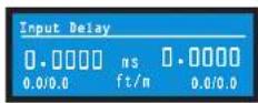
Input Delay: Sets the input signal delay in each channel. Turn each channel's Encoder knob to vary the delay. The delay step size is speed sensitive. Pressing the encoder enables or disables the Delay.
Below each channel's delay setting is the equivalent distance in feet and meters. For example, 10 ms is the signal delay of sound traveling 11.3 feet or 3.4 m.
Output Delay: Sets the output signal delay in each channel. Turn each channel's Encoder knob to vary the delay. The delay step size is speed sensitive. Pressing the encoder enables or disables the Delay.
Below each channel's delay setting is the equivalent distance in feet and meters. For example, 10 ms is the signal delay of sound traveling 11.3 feet or 3.4 m.

Operation Manual
LED Meter Display Type : Here you can set the LCD bar meters to display average or peak levels. Turn an Encoder knob to select the option, then press the knob to confirm your selection.

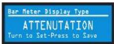
Bar Meter Display Type: You can select what the bar meters will display in the Attenuator Screen. Press an Encoder knob to select Attenuation, Input Levels, Output Levels, or Thermal %. Attenuation is displayed as the length of the bar meters in the Attenuation screen that appears on startup. The meters display average input levels and output levels.
LevelMax - Clip Limiter: Limits the peak output voltage to just below clipping for each channel. Press an Encoder knob to turn it OFF or ON.

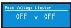
LevelMax- Peak Voltage Limiter: Limits the peak output voltage to a level that you set, either OFF or 1 to 500 volts, for each channel. Press an Encoder to turn on the Limiter. Once it's on, turn the Encoder to set the voltage. Additional controls, such as attack and release, are available through System Architec.
LevelMax - RMS Voltage Limiter: Limits the output rms voltage to an amount that you set, either OFF or 1 to 500 volts, for each channel. Press the Encoder to turn on the Limiter. Once it's on, turn the Encoder to set the voltage.

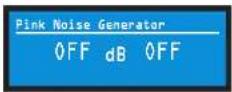
Pink Noise Generator: Press an Encoder knob to turn on the generator. Its level will read -100 dB. Adjust the noise level from -100 dB to +20 dB in 0.5 dB stops by turning Encoder 1 or 2. To turn off the generator, press an Encoder knob or go to another menu item.
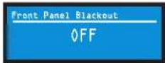
Front Panel Blackout: This screen lets you black out the front panel display unless you press a front-panel button or turn an Encoder. This feature turns off the LCD backlight and all front panel LEDs except for the fault LEDs and power switch green LED. After blackout is enabled, an Encoder press/turn will "reactivate" the display. If no button is pressed/turned for 5 seconds, the display will return to blackout mode.
Exit: To exit the Advanced Menu and go to the Attenuation screen, press Menu/Exit once.
4 Advanced Operation
4.2.4 MONITOR MENU
This menu lets you monitor the status of the amplifier. Starting from the Attenuation Screen, press Menu, then press Prev four times. Or, starting from the Advanced Menu screen, press Next to go to the Monitor Menu screen. Then press an Encoder knob to access the selections in this menu.
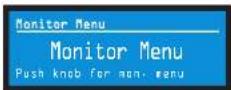
Load Monitoring: Press an Encoder knob to turn speaker load monitoring on or off for either channel. When load monitoring is on, the load connected to the amplifier output is displayed. The text below the reported load indicates whether the value is within the limits set in System Architect. OFF means load monitoring is off. LOW means the load is below limits. HIGH means the load is above limits. NORMAL means the load is within limits.

Thermal %: This indicates the amplifier temperature in percent, where 100% is the maximum allowable temperature. If Thermal % reaches 100%, the amplifier is out of thermal headroom and has shut down (or will very soon). Measurements are shown for Channel 1, Channel 2, and the power supply.
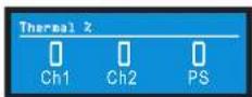
Thermal Temp deg. C: This screen displays the temperature in degrees Celsius of the Ch. 1 output devices, Ch. 2 output devices, and the power supply.

AC Voltage: This shows the AC line voltage at the AC cord inlet to the amplifier.

Operating Time: This displays the number of hours the amplifier has been on since manufacture. Like a car's odometer, it shows the total amount of operating hours and cannot be reset. All I-Tech HD amplifiers come with a variable amount of operating time on them due to burn-in and testing before shipping.

Watts Output: This displays the slow-averaged continuous output power of each channel in watts.

Exit: To exit the Monitor Menu and go to the Attenuation screen, press Menu/Exit once.
4.2.5. ALERT MENU
To access this menu from the Attenuation screen, press an Encoder knob, then press Prev three times. This menu displays a wide variety of errors in the signal, amplifier, or load. Push an Encoder knob to see the selections in the Alert Menu.

Amp Output Clip Errors: A clip error occurs if the number of clip events in the amplifier output exceeds the value set with the Count slider (within the time set by the Time slider) on the Amplifier Settings page in System Architect.
When an error occurs, the count displayed in this screen is incremented, and the operating time since the error is displayed.
To clear this screen, press and release an Encoder. The display will prompt you to confirm your choice by pressing and holding the Encoder.

Analog Input Clip Errors: A clip error occurs if the number of clip events in the analog input exceeds the value set with the Count slider (within the time set by the Time slider) on the Amplifier Settings page in System Architect.
When an error occurs, the count displayed in this screen is incremented, and the operating time since the error is displayed.
To clear this screen, press and release an Encoder. The display will prompt you to confirm your choice by pressing and holding the Encoder.
NOTE: You must use System Architect to enable error reporting and set its limits.

Thermal Errors: This screen lets you view thermal errors without using the control software. A thermal error occurs if the amplifier thermal % exceeded the value set with the Thermal slider on the Amplifier Settings page in System Architect.
When an error occurs, the count displayed in this screen is incremented, and the operating time since the error is displayed.
To clear this screen, press and release an Encoder. The display will prompt you to confirm your choice by pressing and holding the Encoder.
NOTE: You must use System Architect to enable error reporting and set its limits.

4 Advanced Operation
Low Limit Load Errors: This screen lets you view low-load errors without using the control software. A low limit load error occurs if the load impedance falls below the value set with the Low Limit spin control on the Amplifier Settings page in System Architect.
When an error occurs, the count displayed in this screen is incremented, and the operating time since the error is displayed.
To clear this screen, press and release an Encoder. The display will prompt you to confirm your choice by pressing and holding the Encoder.
NOTE: You must use System Architect to enable error reporting and set its limits.

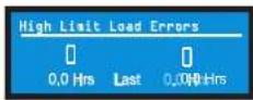
High Limit Load Errors: This screen lets you view high limit load errors without using the control software. A high limit load error occurs if the load impedance rises above the value set with the High Limit value on the software Control Panel.
When an error occurs, the count displayed in this screen is incremented, and the operating time since the error is displayed.
To clear this screen, press and release an Encoder. The display will prompt you to confirm your choice by pressing and holding the Encoder.
NOTE: You must use System Architect to enable error reporting and set its limits.
Operation Manual
SLM (Sweep Load Monitoring) Errors: This screen lets you view SLM errors without using the control software.
When an error occurs, the count displayed in this screen is incremented, and the operating time since the error is displayed.
To clear this screen, press and release an Encoder. The display will prompt you to confirm your choice by pressing and holding the Encoder.
NOTE: You must use System Architect to enable error reporting and set its limits.

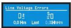
Line Voltage Errors: This screen lets you view line-voltage errors without using the control software. A line voltage error occurs if the line voltage falls outside the values set with the High/Low Limits slider on the Line Voltage Page of the Control Panel.
When an error occurs, the count displayed in this screen is incremented, and the operating time since the error is displayed. The "Low" and "High" indicators show whether the line voltage was below or above the line-voltage limits.
To clear this screen, press and release an Encoder. The display will prompt you to confirm your choice by pressing and holding the Encoder.
NOTE: You must use System Architect to enable error reporting and set its limits.
Fan Errors: When a fan error occurs, the count displayed in this screen is incremented, and the operating time since the error is displayed.

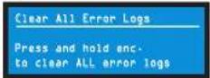
Clear All Error Logs: In this screen, you can press and hold an Encoder knob to clear all the error logs.
Exit: To exit the Alert Menu and go to the Attenuation screen, press Menu/Exit once.
4.2.6 NETWORKING MENU
To access this menu from the Attenuation screen, press an Encoder knob, then press Prev twice. This menu has screens for setting up audio network parameters. Push an Encoder knob to see the selections in the Networking Menu.

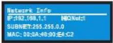
Network Info: This screen displays information about the audio network; IP address, HiQnet address, Subnet and MAC address. Section 9.1 of this manual explains these terms.
Manufacturing Info: This screen displays information about your I-Tech HD amplifier: model number, firmware version, serial number, and amplifier date code.

HiQnet Node Address: This screen lets you set the HiQnet address of this amplifier (a node in the network). Turn an Encoder knob to set the address, then press the knob to save your setting.

4 Advanced Operation
DHCP: Turn an Encoder knob to turn DHCP on or off, then press the knob to confirm your selection. With DHCP enabled, the IP address of the amplifier might change at power-up. See System Architect Help files for more information on DHCP.

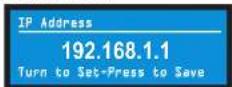
IP Address: You set the IP address of the amplifier here. See Section 9.1 for more information on IP Address. This function is disabled when DHCP is enabled.
- Press an Encoder knob to access the left three digits, then turn the knob to set the number.
- Press again to access the middle three digits, then turn the knob to set the number.
- Press again to access the next digit to the right, then turn the knob to set the number.
- Press again to access the right-most digit, then turn the knob to set the number.
- Press again to save the IP address.
Subnet Mask: You sell the Subnet Mask of the amplifier here. See Section 9.1 for more information on Subnet Mask. This function is disabled when DHCP is enabled.
- Press an Encoder knob to access the left three digits, then turn the knob to set the number.
- Press again to access the middle three digits, then turn the knob to set the number.
- Press again to access the next digit to the right, then turn the knob to set the number.
- Press again to access the right-most digit, then turn the knob to set the number.
- Press again to save the Subnet Mask.

4.2.7 COBRANET MENU
To access the CobraNet Menu from the Attenuation screen, press an Encoder knob, then press Prev. This menu has selections for setting CobraNet parameters. Press an Encoder knob to access the CobraNet Menu selections. See Section 9.2 and the System Architect Help files for more on CobraNet.

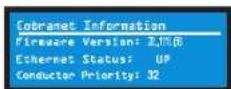
CobraNet Information: This screen displays information about the CobraNet network: The firmware version, ethernet status (down or up), and conductor priority.
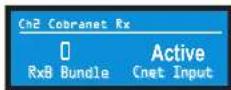
Ch1 CobraNet Rx: Turn the left Encoder knob to set the number of the RxA Bundle for Channel 1. Turn the right Encoder knob to set the CobraNet input for Channel 1. The word "Active" appears if there is audio on the bundle. Bundles 1-8 are available at 48 kHz sampling rate, and bundles 1-4 are available at 96 kHz sampling rate.

Ch2 CobraNet Rx: Turn the left Encoder knob to set the number of the RxA Bundle for Channel 1. Turn the right Encoder knob to set the CobraNet input for Channel 2. The word "Active" appears if there is audio on the bundle. Bundles 1-8 are available at 48 kHz sampling rate, and bundles 1-4 are available at 96 kHz sampling rate.
CobraNet Tx: Turn the left Encoder knob to set the number of the TxA Bundle for Channel 1. Turn the right Encoder knob to set the TxA position for Channel 2.

CobraNet Conductor Priority: Turn an Encoder knob to set the priority number of the CobraNet channel. Press the knob to confirm your choice. See Section 9.2 for more on CobraNet conductor priority.

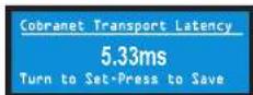
CobraNet Transport Latency: Tum an Encoder knob to set the CobraNet transport latency: either 5.33, 2.66, or 1.33msec. Press the knob to confirm your choice. This latency must match the Cobranet source for proper Cobranet reception.
4 Advanced Operation
4.3 Presets
4.3.1 Introduction
Your I-Tech HD amplifier has a wide variety of onboard Digital Signal Processing (DSP). Some applications for this DSP are speaker configuration (setting the drive levels, frequency bands, delays and limiting for your particular speakers), EQ filtering, compression, and much more. Those functions are described in Section 4.6. System Architect software lets you adjust the DSP settings, such as filler slope, compression ratio, EQ frequency bands, and so on.
A preset is a group of DSP settings that configure the amp for a specific application. For example, you might use one preset that optimizes the amp's DSP for a JBL Vertec Line Array. You might use another preset that sets up the DSP for a stereo pair of loudspeakers of your choice. You can choose any of 50 presets with the LCD Control Screen.
Preset 1 is the factory default preset and cannot be overwritten. It sets up the amplifier for stereo operation with no DSP.
The I-Tech HD amplifier works with two types of presets.
-
User presets. Using System Architect, you can create your own custom DSP presets, label them, and send them to the I-Tech HD amplifier. The amp stores those presets in firmware. You can recall those presets from the LCD Control Screen.
-
Downloadable presets. Crown and JBL engineers have designed presets that are optimized for various JBL loudspeakers, such as Vertec Line Arrays. You can download presets from the I-Tech pages in the Crown website www.crownaudio.com. Then in the software, or with a USB drive, send the preset files to the I-Tech HD amplifier, where you can recall them from the LCD Control Screen.
We will describe each type of preset in detail.
4.3.2 User Presets
User presets are DSP presets that you set up. This is the basic procedure:
1. Adjust the DSP settings as desired in the System Architect soft ware (not with the LCD Control Screen).
2. Save this group of settings as preset. Give it a label.
3. Download the preset to the I-Tech HD amplifier. See the software Help file for details. As soon as you save the setting as a preset, it is sent to the amplifier. Another option, described on the next page, is to transfer the preset file using a USB drive.
4. Select that preset from the LCD Control Screen. The preset will automatically set the DSP parameters as you set them up in the control software.
Setting some parameters of the DSP in the I-Tech HD amplifier is done using the control software, not by the amplifier's LCD Control Screen. For example, if you want to set filter Q, compression ratio, or graphic EQ, you would do so within the System Architect software.
- When you want to recall the preset, select it from the Preset screen in the LCD display. The preset will automatically set the DSP parameters as you set them up in the control software.
4.3.3 Downloadable Presets
Crown and JBL engineers have designed I-Tech HD DSP presets that are optimized for various JBL loudspeakers, such as Vortec Line Arrays. To use them, follow this procedure in System Architect:
-
Go to the I-Tech pages at www.crownaudio.com.
-
Select Downloads.
-
Click on the file of your choice. It will download to your computer.
- In System Architect, see the Help file on Presets for details on downloading the pre set to an I-Tech HD amplifier. Basically, you will open and engage a data frame. The file will overwrite the preset you designate. Another option, described on the next page, is to transfer the preset file using a USB drive.
- Recall the preset from the LCD Control Screen. Then your amp will be configured to work with the specified loudspeaker model.
Section 4.8.19 describes the Presels Manager screen in System Archiled.
4 Advanced Operation
4.4 File Transfer Via the USB Port
On the front panel of the amplifier is a USB Type A port which can transfer files either direction between a USB flash drive and the amplifier. These files can be of two types:
A Preset file, which contains amplifier DSP settings for a specific loudspeaker/amplifier configuration.
A Device file, which contain all 50 presets and the current amplifier DSP settings.
When you plug in the drive, the amplifier defaults to a file-exchange mode and is muted. Then you can load or save individual files. No computer is needed for this file transfer.
How to transfer a file from a USB flash drive to the amplifier:
- The file must reside in the flash-drive root (top-level) directory.
- Plug the flash drive into the amplifier's USB port on the front panel.
- The screen asks if you want to load or save a file. Press the left Encoder to LOAD a file.
- The screen asks whether you want to load a device file or preset file. Press the left Encoder to load a device file, or press the right Encoder to load a preset file.
- The screen says "Select File to Load." Turn an Encoder to select the file.
- If you are loading a preset, the front panel shows the acceptable files in the flash drive root directory. Turn the Encoder to view the files; press the Encoder to select. Note: You can't explore folders or subfolders.
- The amplifier loads the file into its memory and displays the Eject Menu. To stop the transfers, press the left Encoder. To continue with more transfers, press the right Encoder.
- Unplug the flash drive. The amp is unmuled and returns to the determined state.
- If desired, recall the preset following the procedures in Sections 4.3.2 and 4.3.3.
How to transfer a file from the amplifier to a USB flash drive:
- Plug the flash drive into the amplifier's USB port on the front panel.
- The amplifier goes into "File Mode" and is muted.
- The front panel asks if you want to load or save a file. Press the right Encoder to select SAVE.
- The screen will ask whether you want to save a device file or preset file. Press the left encoder to save a device file, or press the right encoder to save a preset file.
- If you chose to save a preset file, the screen says "Select Preset to Save."
- The screen shows the preset files in the amplifier's memory. Turn an Encoder to view the files; press the Encoder to select.
- The amplifier's Preset file will be saved to a default filename in the flash-drive root directory. If the default filename already exists, a number will be appended to the end of the filename.
- You will see the Eject Menu. To stop the transfers, press the left Encoder. To continue with more transfers, press the right Encoder. Unplug the drive when finished.
- Unplug the flash drive. The amp is unmuted and returns to the determined state.

flowchart
graph TD
    A["Insert USB Device"] --> B["USB Main Menu LOAD or SAVE"]
    B --> C["Load a File DEVICE PRESET"]
    B --> D["Save a File DEVICE PRESET"]
    C --> E["Load Device File"]
    C --> F["Load Preset File"]
    D --> G["Save Device File"]
    D --> H["Save Preset File"]
    E --> I["Select file to load"]
    F --> J["Select file to load"]
    G --> K["Select Preset to Save"]
    H --> L["Select Preset to Save"]
    I --> M["(Pop-up box) Loading File Successful"]
    I --> N["(Pop-up box) Loading File Failed!"]
    J --> O["(Pop-up box) Overwriting Preset Successful"]
    J --> P["(Pop-up box) Overwriting Preset Failed!"]
    K --> Q["(Pop-up box) Save to USB Successful"]
    K --> R["(Pop-up box) Save to USB Failed!"]
    L --> S["(Pop-up box) Save to USB Successful"]
    L --> T["(Pop-up box) Save to USB Failed!"]
    M --> U["EJECT MENU"]
    N --> U
    O --> U
    P --> U
    Q --> U
    R --> U
    S --> U
    T --> U
    U --> V["Ch1 Enc"]
    U --> W["Ch2 Enc"]
    V --> X["DONE"]
    W --> X
    X --> Y["NOTE: Pressing any of the navigation buttons (MENU, 'PREV' or 'NEXT'), at any time will go to the "EJECT-MENU" selection screen."]
Figure 4.3 USB File Transfer Flow Chart
4 Advanced Operation
4.5 List of Pop-Up Boxes and Descriptions
These messages may appear on the LCD screen.
If N/A is displayed, the particular menu has been locked out via System Architect software.
| Lockout | "Lockout" is displayed when front panel lockout has been enabled from either the software or front panel. It prevents any changes from the display. |
| USB Lockout | "USB Lockout" is displayed when USB lockout has been enabled from the software. It disables all USB functions. |
| Invalid Subnet | An invalid subnet mask was selected. |
| Invalid Address | An invalid IP address was selected. |
| Preset Loaded | The selected preset has been successfully loaded. |
| Address Changed | The selected address has been modified. Applies to HiQnet node address, IP address and subnet mask. |
| DHCP Changed | The current state of DHCP has been changed to either ON or OFF. |
| USB Fault Overcurrent! | The USB drive is drawing more than 500mA of current. |
| Device File is not valid! | The selected USB device file cannot be loaded because it is not valid. This is most likely a device file formatting problem. Try to create a new device file. |
| Loading File FAILED! | Loading the preset or device file from the USB device failed. This could be due to the format or contents of the file. |
| Loading File Successful! | Loading the preset or device file from the USB device was successful. |
| Confirm Change (Press knob again) | Displayed after the first button press. To continue, the user must release the button and press it again. |
| Confirm Change (Press and Hold) | Displayed after the first button press has been released. To continue, the user must press the button again. |
| Press and Hold (Hold knob) | Displayed after the second button press. To continue, the user must continue to hold the button for at least 2 seconds. |
| Change cancelled | To modify this parameter, the encoder button must be pressed twice with the second press being held down for at least 2 seconds. This message indicates that the encoder button was not properly pressed and/or held down. |
| No Change Selected | The selected object to change has not been modified from the current value. |
| Changes Disabled | The display does not have permission to change this parameter. The display observes HiQnet access rights role 4. Individual screens' parameters can be user defined as Write Protected and/or Read Protected. When a parameter is Read Protected, a "N/A" is displayed. |
| Change Failed! | The selected change was not made. It may have been out of range or invalid. |
4 Advanced Operation
4.6 Digital Audio Options (AES/EBU)
Digital audio inputs allow you to keep the amplifier input signals in the digital domain. Keeping the input signal digital reduces the number of Digital-to-Analog and Analog-to-Digital conversions. This provides better sound quality and reduces pickup of electrical interference.
The AES/EBU connector provides the most widely accepted format. Con nect an AES/EBU signal to the AES/EBU connector on the rear panel. If the amplifier's low-voltage power supply is lost for any reason, the AES input signal goes directly to the AES output. The amplifier has a digital buffer converter so it will adapt to any AES sample rate between 32 and 96kHz that is sent to it.
4.7 Networking the Amplifier
If you need help understanding network concepts, please see Appendix A on Network and CobraNet Basics. Please check the System Architect help file for directions on how to use its networking configuration tools.
An I-Tech HD amplifier may be used in an existing I-Tech network and can use existing I-Tech device or venue files.
You can make the following settings via the front panel or by using the Network Trouhleshooter:
HiQnet node address
DHCP off/on
IP address
Subnet mask
You cannot set the CobraNet IP address via the front panel.
4.7.1 Network Troubleshooter
The network troubleshooter can assist you in setting up your HiQnet network for the first time. Using the troubleshooter, you can address your components and be informed of addressing and other errors in the system. Please note that this wizard is designed to work with devices that are on the same physical network segment as the computer it is running on. It will not work through a router.
Select Network Card
The first page of the wizard lists all the network adapters currently in the computer. If you have more than one adapter, you can scroll through the list and see the IP Address assigned to each card.
If you have a card with an IP address of 0.0,0.0, it typically means one of several things:
-
The card is disabled.
-
The card is not connected to a network.
-
The card is setup to obtain its address from a DHCP server, and no DHCP server is available.
Select the card that is connected to the HiQnet system and click the Next button. The Wizard will walk you through the rest of the process. Please see the System Architect online help for more information.
4.8 Software-Controllable Onboard DSP
Crown's latest-generation Digital Signal Processing is built into the I-Tech HD amplifier. Its 24-bit/96kHz converters offer extremely low noise and extended dynamic range. When you use an I-Tech HD amp, the loud speaker processors, crossovers, limiters and delays are in the onboard DSP – so you don't need those rack-mounted devices. This drastically cuts setup time, commissioning, rack space and costs.
The I-Tech HD's DSP can be monitored and controlled with a computer running System Architect software, and connected to the amplifier Network Connector by a network Category 5 cable.
Some applications for this DSP are:
- Set up signal flow
- Optimize system gain structure
- Set up speaker configurations (set the drive levels, frequency
hands, delays and limiting for your particular speakers)
- Set up EQ, filtering, compression, and much more.
The next several pages explain some of the available DSP functions. See the System Architect Help files for more detailed information.
4 Advanced Operation
4.8.1 Amplifier DSP Selection Screen
On the left of this screen is the Input Signal Level Monitor (explained later on this page). On the right side are rows of DSP selection buttons for each channel. When you click on a button, a control panel opens for that button's function.
Also on the right are buttons that open control panels for these functions:
- Amplifier mode (dual, bridge-mono, Input Y)
• Signal generator (pink noise and sine wave) - Amplifier information
- Recall and store presets
- Preset manager
- Apply to others (apply this amplifier's DSP settings to other devices)
We'll explain each of these functions on the next several pages.
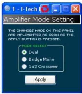
4.8.2 Amplifier Mode
This is switchable between dual, bridge-mono and 1x2 (input Y).
Operation Manual

4.8.3 Input Level, Mute, Link, Level Meters, and Indicators
This panel is on the left side of the 1-Tech main control panel shown above. Channel 1 and 2 Level Controls set the input signal level of each channel. Each channel can be muted, and both faders can be linked with the Link button.
Input Signal Level Meter
The measure mont range is from 0dBFS to -40dBFS with 0.5dB resolution. Each audio channel has the following monitors:
- Switched Audio Input: This meter shows only the switched (selected) audio input after the Input Audio Router.
- Clip Indicator
Output Signal Level Meter
The mea surement range is from 0 dB to -40 dB with 0.5 dB resolution. The monitors are scaled so that 0 dB is referenced to the full rated output voltage of the amplifier. The left meter is rms and the right meter is peak. An output clip indicator is provided.
Indicators
Temp: Lights if the temperature of the amplifier is too high and the amplifier is near shutdown. Green: Thermal headroom used up is less than 59%.
Yellow: Thermal headroom used up is 60-80%.
Red: Thermal headroom used up is more than 81%.
Limit: Lights when the amplifier signal is being limited.
Load: Lights when the load impedance is out of range.
Ready: Lights when the amplifier is on and ready to supply power.

4 Advanced Operation
4.8.4 Input Signal Router
Each channel of the I-Tech's signal processing has an input Signal Router that lets you choose the audio signal that will be used by the channel. Choose one of the following configurations:
- Analog Audio: This is the audio input from the audio connector on the back panel of the amp. Choices for the Analog Audio input are Channel 1, Channel 2, or a sum of Channels 1 and 2.
- Digital Audio: This is the audio input from the AES/EBU connector or CobraNet connector on the back panel of the amp. It can be set up for Digital with Analog Backup or Digital with Analog Override:
• Digital with Analog Backup
The input takes the digital signal as its source when the digital signal (or just the digital clock) is present. If the digital lock is lost, the input switches to the selected Analog Source. Once that digital lock is found again, the input switches back to the selected digital source. This works even when the digital signal has no audio but is sending a clock signal.
• Digital with Analog Override
The input takes the digital signal as its source. If the analog signal level is greater than an Analog Signal Detect Threshold that the user defines, the input switches to the analog signal. As long as the analog signal level exceeds the threshold, or as long as its level falls below threshold for a user-defined hold time, the input remains the analog signal.
Analog Signal Detect Threshold (-100 dB to 0 dB)
This option is not displayed unless override is selected. If the selected analog signal exceeds the threshold level, the analog signal becomes the source for this input rather than the selected digital input source. Use the numeric spin box or the fader provided to set the threshold.
Hold Time (0 - 60 seconds)
This option is not displayed unless override is selected. Once an overriding analog input signal falls below threshold, the Hold Time determines how long the input will continue to be the selected analog input before reverting to the selected digital input. Use the numeric spin box or the factor provided to set this time.
The control operation will vary based on the mode that is selected.
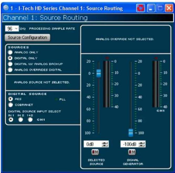
4 Advanced Operation
4.8.5 Source Configuration
In this screen you can configure the levels and settings of the analog, AES and CobraNet inputs. The input signal of each channel can be independently muted.
The I-Tech HD amplifier can be set to work as a fixed gain amplifier: any input signal is given a fixed amount of gain, either 26dB or 32dB. In addition, you can set the input sensitivity to determine how much gain is provided. See Section 4.8.20 for more details.
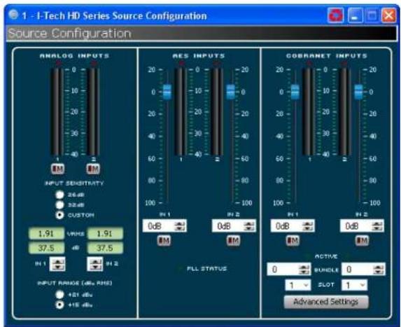
4.8.6 CobraNet Advanced Settings
In the CobraNet Advanced Settings screen you can set the parameters shown here. Indicators that are green can't be modified.
The latency on this screen is the CorbaNet transport latency or buffering. This latency must be set to the same latency as the source CobraNet device.
The Foldback control panel lets you select the items to transmit via CobraNet. Selections available are the Analog Inputs, Amplifier Outputs or AES input signal. The audio can be routed out through only one bundle.

4 Advanced Operation
4.8.7 Input Signal Compressor
An input signal compressor is available for each channel. Several parameters control this feature:
On/off button: Enables or disables this function.
Threshold: Sets the level, in dBu, above which the compressor begins to attenuate the input signal. This level corresponds to the input level meter reading. The compressor is "lead-forward," meaning that the level detection point is located before the gain control stage. The range is from 120 dBu to -50 dBu.
Attack Time: Sets the attack time of the compressor. The attack time is defined as the time it takes the compressor to attenuate the signal gain by 20 dB. The range is from 1 millisecond to 0.1 second.
Release Time: Sets the release time of the compressor. The release time is defined as the time it takes the compressor to increase the signal gain by 20 dB. The range is from 10 milliseconds to 10 seconds.
Compression Ratio: Sets the compression ratio of the compressor. The ratio is the relation between the amount of attenuation applied by the compressor verses the amount that the input signal is over the threshold. The available settings are 2:1 to 32:1.
Makeup gain: The amount of gain you want to apply to the compressed signal to raise it to a higher level.
Knee width: The knee of the compression curve is the transition point between no compression and compression. The wider the knee, the more gradual is the transition — so compression is not so obvious when the signal is close to threshold.
Beyond the controls for each channel, a single-control CompressorTie connects the compressors together. The compressors are tied at their sense points, meaning that the greater of the two input signals will be used as stimulus for both compressors. Each compressor will still compress based on its individual threshold, attack, release and ratio settings.

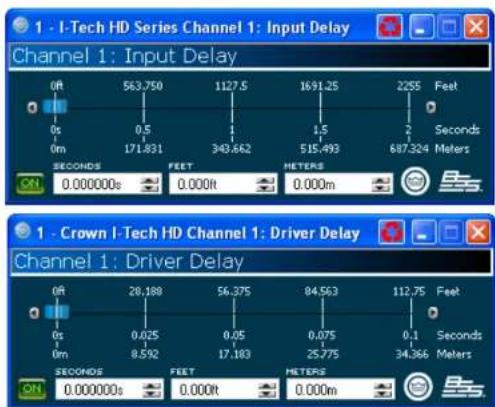
4.8.8 Input Delay and Driver Delay
In these screens you can set the signal delay for each channel in seconds, feet or meters.
4 Advanced Operation

line
| Frequency | Amplitude (dB) | | --------- | -------------- | | 114.06 | 21.97 | | 1.21 | -14.87 | | 5.5 | 12.17 |4.8.9 Input EQ and Output EQ
These screens let you adjust channel equalization at up to 16 frequencies. You can select filter type, frequency, gain, and bandwidth in octaves or Q as set by the user preferences in System Architect. Changes to the equalizer's frequency response can be done by typing in parameters or by click-dragging the response curve.
4 Advanced Operation

4.8.10 Crossover Filters
The Crossover section lets you use infinite impulse response (IIR) or finite impulse response (FIR) filters for the crossover.
FIR advantages: FIR has a longer processing latency but has less phase artifacts compared to IIR. FIR allows for brickwall, 48dB/oct and 24dB/octave filters.
IIR advantages: FIR has one processing block per channel; IIR has one or more. For example, you can place an FIR at only one end of a channel, but you can place an IIR at either end.
The amplifier contains two FIR blocks which can be used in various configurations:
- 2x2 mode: One FIR filter per channel can be used.
- Bridge mono mode: Both FIR fillers can be used.
- 1x2 mode: Two modes are available – Duplicate or Unique. In Duplicate mode the same settings are used on both channels, allowing two FIR filters per bandpass. In Unique mode the FIR filters are limited to one per bandpass. However, if the High Pass of Channel 1 and Low Pass for Channel 2 are set to identical slopes and frequencies, you can use FIR on all the bandpasses. The logic for this operation is built into the software controls. In addition, the Processing (FIR) latency sets the minimum frequency that can be set for an FIR.
A polarity inverter button lets you change the polarity of each channel independently.
Each audio channel has three separate places where filters can be placed in the system: input EQ (16 filters), Crossover, and Output EQ. Up to 24 filters per channel are available, plus crossover filters and 4 filters for the signal generator. Each filter has up to 12 -24cB of gain. The following filters are available:
• Lowpass: Bessel 2-4, Butterworth1-4, and Linkwilz-Riley 8
• Highpass: Bessel 2-4, Butterworth1-4, and Linkwitz-Riley 8
• Lowshelf: Low-frequency shelving EQ
• Highshelf: High-frequency shelving EQ
- Lowpass EQ: Variable bandwidth, can be expressed as Q (0.100 to 35) or Octaves (0.041 to 6.672)
• Highpass EQ: Variable Q from 0.1 to 25
• Parametric EQ: Variable Q form 0.1 to 35
Operation Manual
4 Advanced Operation
4.8.11 LevelMax Suite
This is a suite consisting of a peak voltage limiter, average power limiter, clip limiter and thermal transducer limiter. First you will set the mode to automatic or advanced:
- Automatic mode: The software determines the best settings based on the signal characteristics. You can modify only the RMS threshold, Speaker Thermal threshold and time constant. Everything else is set automatically.
- Advanced mode: You can modify the RMS threshold, Speaker Thermal threshold, time constant, Peak Threshold and Peak/RMS release.
Peak Voltage Limiter
This limits the peak voltage output of 4.8 the amplifier. On: Enables or disables this function. You'll set the parameters below:
- Threshold: Sets the level, in absolute voltage, which the limiter will allow from the amplifier. The range is from 12Vin to 255Vin
- Attack Time: Sets the attack time of the limiter. The attack time is defined as the time it takes the limiter to attenuate the output signal by 20 dB. The range is from 1 millisecond to 100 milliseconds. The instant setting attack time is instant (0 millsecond).
- Release Time: Sets the release time of the compressor. The release time is defined as the time it takes the limiter to increase the output signal by 20 dB. The range is from 10 milliseconds to 10 seconds.
Average Power Limiter
This limits the long-term output power of the amplifier. You'll set the parameters below:
- Threshold: Sets the average power level, in watts, which the limiter will allow from the amplifier channel. The range is from 10 watts to 10,000 watts. This level should be set to the connected loudspeaker's long-term power rating. Also you must enter the loudspeaker's nominal impedance.
- Attack Time: Sets the attack time of the limiter. The attack time is defined as the time it takes the limiter to attenuate the output signal by 20 dB. The range is from 1 second to 30 seconds.
- Release Time: Sets the release time of the compressor. The release time is defined as the time it takes the limiter to increase the output signal by 20 dB. The range is from 1 second to 30 seconds.
Clip Eliminator: This limiter monitors the clip events and attenuates the input signal to prevent amplifier clipping. The attack and release times are preset to optimum rates. Only one parameter controls this limiter. "Enable" enables or disables this limiter.
A lookahead feature prevents overshoot of the limiters. These settings were developed with JBL to protect the speakers from overvoltage.
Transducer Thermal Limiting
This limits the long-term output power of the amplifier to what the loudspeaker load can handle without overheating and going into thermal compression. You can set the thermal level at which the thermal limiter engages, the thermal response time and thermal voltage. Your loudspeaker manufacturer might be able to provide this information. Meters show the amplifier output level in dBFS; and peak, rms, and total gain reduction.
Operation Manual

4.8.12 Front Panel Security
Here you can choose which amplifier LCD screens to lock so they can't be changed.
![Front Panel Display Screen Security Front Panel Display is Locked USB Port is Locked [FW] Main/Menu [RW] Alternation [R] Sample Rate (Read Only) [RW] Analog Input Sensitivity [RW] Select [RW] Area Mode [RW] Locate [FW] Advanced [RW] Alternator Limits [RW] Alternator Link [RW] Input Sources [RW] Analog Source Select [RW] Maximum Analog Input [RW] Digital Source Select [RW] ACS Source Select Read Write OK Apply Cancel](/content/2026/05/1109799/images/bf4792e6601786899c5b212931e2a73b56e84bc5ffc7a1d5a6831402cb14a977.jpg)
4 Advanced Operation
4.8.13 Amplifier Settings
The Amplifier Output Enable button turns each channel on or off.
Error Reporting
The I-Tech amplifier can detect four different error conditions per channel and errors in the AC line voltage. Each error type can be individually configured to report the error through the network. Network reported errors appear in the control software Event Log. The following describes each error source.
Clip: A clip detector is provided each channel. These monitors will indicate any clip condition (>0.05% distortion) in the amplifier channel. The clip detectors also can indicate Thermal Level Control limiting.
The I-Tech HD can be configured to report if an excessive number of output clip events occur in either amplifier channel. The clip events are consider an error if they exceed the defined count per the defined unit of time.
The Count Control sets the maximum number of events before the error is reported. The range is 1 to 100. The Time Control defines the amount of time that the events are counted before starting the counting process over. Its range is 1 to 10 seconds. Note: Clip events are defined as the start of each clip and every 10 milliseconds the amplifier is in clip thereafter. Using a high count setting with a short time setting may result in clip errors never being detected.
Thermal: Errors can be generated for excessive temperature in the output section of the amplifier channel. The Threshold Control sets the level that, if exceeded, will generate the error report. This control has a range of 1 to 100%.
Line voltage: The AC line voltage can be monitored and an error generated whenever the voltage is outside of the limits set by the soft ware.
Fan: Using the ON button, you can enable reports of any lan errors.
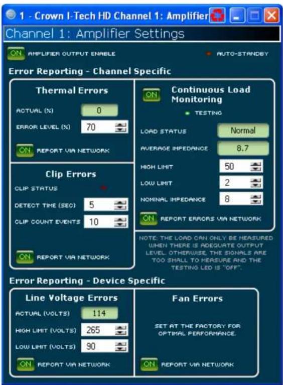
Continuous Load Monitoring
The load supervision feature allows real-time monitoring of the load connected to each amplifier channel. When enabled, the I-Tech continuously monitors the amplifier output voltage and current, and calculates the long-term average load impedance. The measured load impedance is compared against the user-defined high and low limits. If either limit is exceeded, the status indicator and, if enabled, the System Architect Error Reporting functions alert the user of the problem. There are six controls and two indicators for each channel:
On: Enables or disables the load-supervision function.
Load Status: This indicator shows the present status of the load impedance with respect to the user-defined high and low limits.
Average Impedance: Sets the expected average impedance for the connected load. This value determines the output signal level required for the test. This parameter is also used by the average power limiter to determine the expected power threshold.
High Limit: Sets the upper bound above which the system will report a "high" error status.
Low Limit: Sets the lower bound below which the system will report a "low" error status.
Average Impedance: Sets the expected average impedance for the connected load. This value determines the output signal level required for the test. This parameter is also used by the average power limiter to determine the expected power threshold. You set this field to the nominal impedance of the connected load per channel.
Report Errors via Network: When this is turned on, high and low load errors are sent via the network to System Architect software.
4 Advanced Operation
4.8.14 Amplifier Information
Information about the amplifier is stored in the software system inventory and is displayed on the software control panels. Information includes manufacturer, model, date code, and serial number. The green items can't be edited.
Channel Labels: Each amplifier includes two labels that you may edit for your own use. Simply type in the text areas. Use these labels to describe the channels of your amplifier. These names will appear in the individual processing blocks.
Attenuator Limits: This lets you set a limit on the attenuators. You can set the maximum attenuation from 0 dB to -100 dB. Once set attenuation cannot be adjusted beyond this level.
NOTE: The attenuator setting must be below the attenuator limit that you are trying to set. For example, if the attenuator is set at -3 dB, you cannot set the attenuator limit below -3 dB unless you decrease the attenuator level.
Blackout Mode: This button lets you blackout the front panel display until you press a front-panel button or turn an Encoder. This feature turns off the LCD backlight and all front panel LEDs except for the fault LEDs and power-switch green LED. After blackout mode is enabled, an Encoder press/turn will "reactivate" the display. If no button is pressed/turned for over 5 seconds, the display will return to blackout mode.

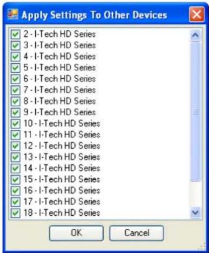
4.8.15 Apply to Others
This screen lets you apply the System Architect settings for your I-Tech HD amplifier to other I-Tech HD amplifiers in the venue file.
4.8.16 Delay (Latency)
Due to the nature of DSP processing, there is some inherent delay or latency within the I-Tech's DSP. These latencies are shown in Table 4 below:
Table 4. I-Tech HD latencies at two sample rates
| Sample rate | ADC DSP DAC Ampli- | fier | Total latency | ||
| 48 kHz 23 | 0μs 668μs | 196μs 54μs | 1.168ms | ||
| 96 kHz 94 | 0μs 333μs | 48μs 54μs | 529μs | ||
These latencies do not include CobraNet Transport Latency and FIR Processing Latency
4 Advanced Operation
4.8.17 Preset Manager
The control settings for all the functions can be stored as presets. Up to 50 presets can be saved in the I-Tech amp's nonvolatile memory. Each preset can be named with a 30 character name describing its function, which is also stored in memory.
- The Store Preset Control saves the current setting to the specified preset.
- The Recall Preset Control recalls the specified presel settings. It appears in the Active Preset field. If you change the settings after recalling a preset, the Store button will turn yellow.
You can drag the presets to place them in a logical order. Also, you can color-code the presets to organize them.
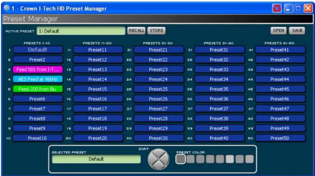
4 Advanced Operation
4.8.18 Signal Generator
Both channels share a noise generator that allows noise to be mixed into the audio signal. This is useful for noise masking applications and testing. Each channel has the following controls:
- Noise On/Off: Turns the noise generator on or off.
- Noise Type: Selects full-spectrum white noise or pink noise.
- Noise Level: Sets the noise level with a fader.
The sine-wave signal generator lets you mix a single tone into the audio signal. Its controls are listed below:
- Sine On/Off: Turns the sine-wave generator on or off.
- Sine Frequency: Sets the frequency anywhere from 20Hz to 20kHz.
- Sine Level: Sets the level of each channel's sinowave signal independently.
The noise generator and sinc-wave generator cannot be used at the same time.

4 Advanced Operation

flowchart
graph LR
    A["Analog input"] --> B["Analog input"]
    B --> C["Analog input sensitivity"]
    C --> D["Source select"]
    D --> E["Output attenuator"]
    E --> F["Fixed gain compensation"]
    F --> G["Limiters"]
    G --> H["Amplifier"]
    I["AES input"] --> J["AES input trim"]
    J --> D
    K["Cobranet input"] --> L["Cobranet input trim"]
    L --> D
    M["Maximum analog input\nLow +21 dBu (0 dB)\nHigh +15 dBu (+6 dB)"] -.-> N["Fixed gain\nLow +21 26/32 dB\nHi +15 32/38 dB"]
Figure 4.4 The Various Gain Settings in the I-Tech HD
4.8.19 Fixed-Gain Mode in the I-Tech HD
Fixed-gain mode makes any I-Tech HD model have the same gain, regardless of output power.
To do that, fixed-gain mode sets the Analog Input Sensitivity to 0 dB gain, then adjusts the Fixed Gain Compensation tader, and the Maximum
Analog Input, to achieve 26 or 32 dB of gain (if the Maximum Analog Input is set Low), or to achieve 32 or 38 dB of gain (if the Maximum Analog Input is set High), no matter what model the amplifier is.
However, In fixed-gain mode, the input trims (Analog, AES, CobraNet) can still be adjusted.
5 Troubleshooting


CONDITION: Power indicator is off and power switch is not illuminated.
POSSIBLE REASON:
• The amplifier has lost AC power.
- The amplifier is not plugged into the power receptacle.
- Rear-panel breaker is off.


CONDITION: Thermal indicator is on.
POSSIBLE REASON:
- The amplifier is becoming too hot for safe operation. Allow amplifier to cool. Check for loads less than 2 ohms, and for excessive input levels. Check for proper ventilation.
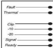


CONDITION: Power Indicator is off and power switch is illuminated.
POSSIBLE REASON:
• The amplifier's power switch is off.
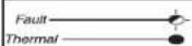


CONDITION: Fault indicator is flashing.
POSSIBLE REASON:
- The amplifier channel has stopped operating. Refer the unit to an authorized Crown Service Center.


CONDITION: Power indicator is flashing.
POSSIBLE REASON
- The AC line voltage has dropped below 15% or has risen above 15% of the rated range.


CONDITION: Power indicator is off and power switch is not illuminated.
POSSIBLE REASON
- Load is wired incorrectly or Output Mode switch. In LCD-screen menu is set incorrectly. Check both.
- Input is overloaded by a signal level that is too high. Turn down your amplifier level controls (Encoders), or turn down the input signal, until the clip light goes out.
Note: If the signal sounds distorted even though the Clip LED is off, the input signal may be distorted before it reaches the amplifier input. Check gain staging and output levels of the mixer or preamp.
"Off/Flashing/On" means that the LED can be off, or flashing, or on.
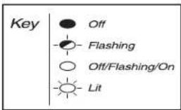
5 Troubleshooting


CONDITION: Yellow LINK ACTIVITY indicator in Ethernet connector does not illuminate or flash.
POSSIBLE REASON:
- Ethernet link is broken.

CONDITION: COND indicator is off.
POSSIBLE REASON:
- There is only one conductor allowed per network system. This indicator is ill only when the amplifier is the conductor.
- Amplifier is in blackout mode. Press or turn an Encoder to reactivate the LCD display.
CONDITION: Computer does not communicate with the network devices.
POSSIBLE REASON:
- Incorrect wiring. See Section 3.5 letter D on network wiring.
- IP Addressing is not done correctly. Use the Network Troubleshooting Wizard in System Architect.
6 Specifications
Minimum Guaranteed Power I-T5000HD I-T9000HD I-T12000HD
| 20 Hz - 20 kHz with 0.35% THD | |||
| Stereo, 2 ohms (per ch.) | 1800W | 2500W | 3500W |
| Stereo, 4 ohms (per ch.) | 2000W | 3000W | 4000W |
| Stereo, 6 ohms (per ch.) | 1250W | 1500W | 2100W |
| Bridge mono, 4 ohms | 3600W | 5000W | 7000W |
| Bridge mono, 8 ohms | 4000W | 6000W | 8000W |
Performance I-T5000HD I-T9000HD I-T12000HD
| Input Sensitivity (volts RMS) for rated output Adjustable in 0.1V stops from | 1.28V to 8V | Adjustable in 0.1V steps from 1.28V to 8V | Adjustable in 0.1V steps from 1.28V to 8V |
| Voltage Gain for full rated power at 8 ohms 37.1 dB to 22.2 dB 37.9 dB to 23.0 dB 40.1 dB to 24.5 dB | |||
| Frequency Response (at 1 watt, 20Hz - 20 kHz) ± 0.25 dB ± 0.25 dB ± 0.25 dB | |||
| Signal to Noise Ratio below rated full-bandwidth power, A-weighted >108 dB >108 dB >108 dB | |||
| Total Harmonic Distortion (THD) at full rated power at 1 kHz | <0.1% | <0.1% | <0.1% |
| Intermodulation Distortion (IMD) 60 Hz and 7 kHz at 4:1, from full rated output to -35 dB | <0.35% <0.35% | <0.35% | |
| Maximum Input Level | +15 dBu or +21 dBu, depending on setting of maximum input level | +15 dBu or +21 dBu, depending on setting of maximum input level | +15 dBu or +21 dBu, depending on setting of maximum input level |
| Latency | 1.16 mS at 48 kHz, 529 μS at 96 kHz | 1.16 mS at 48 kHz, 529 μS at 96 kHz | 1.16 mS at 48 kHz, 529 μS at 96 kHz |
| A/D, D/A Converters | 24-bit 96 kHz Cirrus Logic | 24-bit 96 kHz Cirrus Logic | 24-bit 96 kHz Cirrus Logic |
| Digital Input | AES/EBU, 24-bit, 32-96 kHz. Onboard sample rate converter. | AES/EBU, 24-bit, 32-96 kHz. Onboard sample rate converter. | AES/EBU, 24-bit, 32-96 kHz. Onboard sample rate converter. |
| Network | Onboard HiQnet and TCP/IQ, compatible with standard 100Mb Ethernet hardware | Onboard HiQnet and TCP/IQ, compatible with standard 100Mb Ethernet hardware | Onboard HiQnet and TCP/IQ, compatible with standard 100Mb Ethernet hardware |
| DSP | 24-bit conversion with 32-bit, floating-point DSP processing | 24-bit conversion with 32-bit, floating-point DSP processing | 24-bit conversion with 32-bit, floating-point DSP processing |
| Attenuators | Speed-sensitive rotary encoders, 0.5 dB steps, range 0 to -100 dB. | Speed-sensitive rotary encoders, 0.5 dB steps, range 0 to -100 dB | Speed-sensitive rotary encoders, 0.5 dB steps, range 0 to -100 dB |
6 Specifications
| Performance I-T5000HD I-T9000HD I-T12000HD | |||
| Damping Factor (8 ohms): 20 Hz to 100 Hz >5000 >5000 >5000 | |||
| Crosstalk (below rated power, 20 Hz to 1 kHz) >80 dB >80 dB >80 dB | |||
| Common Mode Rejection (CMR) (20 Hz to 1 kHz) | >55 dB, typically >70 dB | >55 dB, typically >70 dB | >55 dB, typically >70 dB |
| DC Output Offset (Shorted input) < ± 3 mV < ± 3 mV < ± 3 mV | |||
| Input Impedance (nominal) | 20 kilohms balanced, 10 kilohms unbalanced | 20 kilohms balanced, 10 kilohms unbalanced | 20 kilohms balanced, 10 kilohms unbalanced |
| Load Impedance (Note: Sale with all types of loads)StereoBridge Mono | 1-2-4-5-16 ohms2-4-8 ohms | 1-2-4-8-16 ohms2-4-8 ohms | 1-2-4-8-16 ohms2-4-8 ohms |
| Required AC Mains | Universal AC Input, 100-240VAC (±15%), 50/60 Hz. Max. AC mains voltage 277VAC. | Universal AC Input, 100-240VAC (±15%), 50/60 Hz. Max. AC mains voltage 277VAC. | Universal AC Input, 100-240VAC (±15%), 50/60 Hz. Max. AC mains voltage 277VAC. |
| AC Line Connector | USA, UK, European, Australia, India | USA, UK, European, Australia, India | USA, UK, European, Australia, India |
| Construction | I-T5000HD | I-T9000HD | I-T12000HD |
| Ventilation | Flow-through ventilation from front to back | Flow-through ventilation from front to back | Flow-through ventilation from front to back |
| Cooling | Dual-zone, microprocessor controlled, continuously variable speed fans | Dual-zone, microprocessor controlled, continuously variable speed fans | Dual-zone, microprocessor controlled, continuously variable speed fans |
| Dimensions | EIA Standard 19-inch rack mount width (EIA RS-310B), 3.5-inch (8.9-cm) height, 16.2-inch (41.1-cm) depth behind front mounting surface | EIA Standard 19-inch rack mount width (EIA RS-310B), 3.5-inch (8.9-cm) height, 16.2-inch (41.1-cm) depth behind front mounting surface | EIA Standard 19-inch rack mount width (EIA RS-310B), 3.5-inch (8.9-cm) height, 16.2-inch (41. 1 -cm) depth behind front mounting surface |
| WeightNetShipping | 28 pounds (12.7 kg)36 pounds (16.3 kg) | 28 pounds (12.7 kg)36 pounds (16.3 kg) | 28 pounds (12.7 kg)36 pounds (16.3 kg) |
6 Specifications
Charts

line
| Freq (Hz) | dB | | --------- | ---- | | 10 | 0.0 | | 100 | 0.0 | | 1000 | 0.0 | | 10000 | -0.5 | | 100000 | -0.2 |Figure 6.1 Typical Frequency Response (1W)
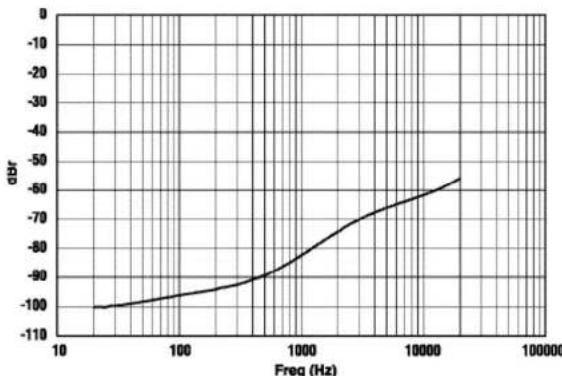
line
| Freq (Hz) | dBR | | --------- | ---- | | 10 | -100 | | 100 | -95 | | 1000 | -85 | | 10000 | -70 | | 100000 | -60 |Figure 6.2 Typical Crosstalk vs. Frequency
6 Specifications
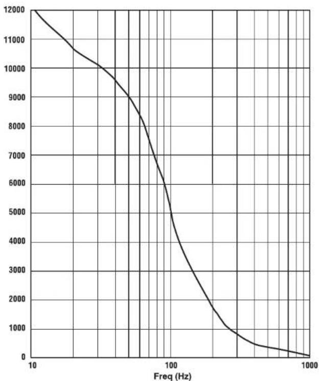
line
| Freq (Hz) | Value | | --------- | ------ | | 10 | 12000 | | 50 | 10000 | | 100 | 7000 | | 200 | 4000 | | 500 | 1000 | | 1000 | 0 |Figure 6.3 Typical Damping Factor vs. Frequency
7 AC Power Draw and Thermal Dissipation
I-Tech 5000HD AC Current Draw and Thermal Dissipation:
Pink noise 12dB crest factor, bandwidth limited 22Hz to 22kHz.
Typical line impedance used.
Data based on both channels driven.
| I-T5000HD | ||||||||||
| Load | 120VAC | 208VAC | 230VAC | Watts Dissipated | Thermal Dissipation | |||||
| Line Current 120VAC | Watts Out Per 1A Amp Line Current | Line Current 208VAC | Watts Out Per 1A Amp Line Current | Line Current 230VAC | Watts Out Per 1A Amp Line Current | Btu/hr kcal/hr | ||||
| Idle (sleep mode) 0.8 0.95 0.9 53 182 157 | ||||||||||
| Idle (awake) 1.6 1.4 1.3 172 587 505 | ||||||||||
| 1/8th Power Pink Noise 8 Ohms/Ch.Typical of program material 16 just at clip. | Ohms/Ch.Ohms Bridge | 5.3 | 59.6 | 3.4 | 94.6 | 3.1 | 102.6 | 305 | 1040 | 262 |
| 4 Ohms/Ch.8 Ohms Bridge | 7.8 | 64.9 | 4.7 | 106.9 | 4.4 | 116.3 | 414 | 1413 | 356 | |
| 2 Ohms/Ch.4 Ohms Bridge | 8.0 | 58.1 | 4.8 | 96.1 | 4.4 | 106.0 | 476 | 1625 | 410 | |
| 1/3rd Power Pink NoiseTypical of program material with severe clipping. 4 Ohms/Ch.Ch.8 Ohms Bridge | 10.9 | 77.1 | 6.6 | 126.2 | 6.0 | 139.9 | 437 | 1491 | 376 | |
| 17.8 | 77.0 | 10.5 | 129.1 | 9.5 | 142.1 | 711 | 2426 | 612 | ||
| 17.7 | 70.3 | 10.7 | 115.3 | 9.4 | 128.7 | 824 | 2814 | 709 | ||
7 AC Power Draw and Thermal Dissipation
I-Tech 9000HD AC Current Draw and Thermal Dissipation:
Pink noise 12dB crest factor, bandwidth limited 22Hz to 22kHz.
Typical line impedance used.
Data based on both channels driven.
| I-T9000HD | ||||||||||
| Load | 120VAC | 208VAC | 230VAC | Watts Dissipated | Thermal Dissipation | |||||
| Line Current 120VAC | Watts Out Per 1A Amp Line Current | Line Current 208VAC | Watts Out Per 1A Amp Line Current | Line Current 230VAC | Watts Out Per 1A Amp Line Current | Btu/hr kcal/hr | ||||
| Idle (sleep mode) 1.0 1.0 0.95 60 205 177 | ||||||||||
| Idle (awake) 2.1 1.7 1.6 225 767 660 | ||||||||||
| 1/8th Power Pink Noise 8 Ohms/Ch.Typical of program material 16 just at clip. 4 Ohms/Ch. | Ohms/Ch.Ohms Bridge | 6.6 | 57.6 | 4.2 | 91.2 | 3.8 | 99.8 | 392 | 1338 | 337 |
| 8 Ohms Bridge | 11.6 | 65.7 | 7.0 | 108.8 | 6.3 | 120.4 | 593 | 2024 | 510 | |
| 2 Ohms/Ch.4 Ohms Bridge | 11.5 | 55.9 | 6.8 | 96.5 | 6.2 | 105.3 | 695 | 2373 | 598 | |
| 1/3rd Power Pink Noise 8 Ohms/Ch.Typical of program material with severe clipping. 4 Ohms | Ohms/Ch.16 Ohms Bridge | 13.6 | 74.4 | 8.1 | 125.3 | 7.4 | 137.2 | 579 | 1977 | 498 |
| Ch.8 Ohms Bridge | 27.6 | 73.9 | 16.0 | 127.2 | 14.3 | 141.0 | 1149 | 3921 | 988 | |
| 2 Ohms/Ch.4 Ohms Bridge | 25.0 | 67.0 | 14.9 | 113.5 | 13.6 | 124.3 | 1223 | 4173 | 1052 | |
7 AC Power Draw and Thermal Dissipation
I-Tech 12000HD AC Current Draw and Thermal Dissipation:
Pink noise 12dB crest factor, bandwidth limited 22Hz to 22kHz.
Typical line impedance used.
Data based on both channels driven.
| I-T12000HD | ||||||||||
| Load | 120VAC | 208VAC | 230VAC | Watts Dissapited | Thermal Dissipation | |||||
| Line Current 120VAC | Watts Out Per 1A Amp Line Current | Line Current 208VAC | Watts Out Per 1A Amp Line Current | Line Current 230VAC | Watts Out Per 1A Amp Line Current | Blu/hr kcal/hr | ||||
| Idle (sleep mode) 0.9 1.1 1.0 62 212 183 | ||||||||||
| Idle (awake) 2.0 1.8 1.6 213 726 625 | ||||||||||
| 1/8th Power Pink Noise 8 Ohms/Ch.Typical of program material 16 just at clip. 4 Ohms/Ch. | Ohms/Ch.Ohms Bridge | 8.3 | 63.6 | 5.1 | 103.3 | 4.7 | 111.8 | 441 | 1504 | 379 |
| 8 Ohms Bridge | 14.6 68.8 | 8.7 | 115.2 | 8.0 | 124.5 | 7012394 | 603 | |||
| 2 Ohms/Ch.4 Ohms Bridge | 14.2 | 62.9 | 8.2 | 106.1 | 7.7 | 113.6 | 764 | 2607 | 657 | |
| 1/3rd Power Pink Noise 8 Ohms/Ch.Typical of program material with severe clipping. 4 Ohms/Ch. | Ohms/Ch.16 Ohms Bridge | 18.1 | 77.4 | 11.0 | 128.3 | 9.9 | 142.0 | 715 | 2439 | 615 |
| Ch.8 Ohms Bridge | 35.1 | 76.3 | 20.8 | 128.6 | 18.7 | 144.2 | 1370 | 4677 | 1179 | |
| 2 Ohms/Ch.4 Ohms Bridge | 33.9 | 69.2 | 19.9 | 118.0 | 17.9 | 131.1 | 1589 | 5425 | 1368 | |
8 Advanced Features
8.1 Protection Systems
Your Crown amplifier provides extensive protection and diagnostic capabilities, including thermal level control, fault indicators, high-pass filtering, DC protect, AC under/over voltage protection, inrush limiting, and variable-speed fans with tachometer feedback. Microprocessor monitors fans, and signals an error via System Architect if fans are not operating.
8.1.1 Thermal Level Control (TLC)
If the amplifier becomes too hot for sale operation, the TLC will engage the input compressor and the clip LED will illuminate. By compressing the input, the amplifier will not generate as much heat and will have a chance to cool down. The degree of compression is proportional to the amount of overheating. This feature allows the show to go on, rather than having the amplifier shut down, and only occurs in extreme situations.
8.1.2 Circuit Breaker
If the current draw of the amplifier exceeds safe limits, this breaker automatically disconnects the power supply from the AC mains.
8.2 Global Switching Power Sup ply with PFC
Thanks to its global power supply, the I-Tech amplifier works anywhere in the world. There's no need to reset an AC mains voltage switch, and no need to order a special model. The amp will work and meet all specs on 100V - 240VAC, 50/60 Hz.
Crown's Switching Power Supply minimizes the amplifier's weight.
Typical non-switching power supplies require large, heavy transformers in order to produce the required power at the output stage. These transformers must be large to operate at 50 to 60 Hz (standard AC supplied by the power company).
By contrast, switching power supplies can operate with a much smaller (and lighter) trans former because they first convert the AC up to a much higher frequency, thereby reducing waste.
Power Factor Correction (PFC) controls how your amplifier draws current from the AC mains. Instead of drawing high-magnitude current spikes that reduce the capacity of your power
distro (and couple noise into other system components). PFC draws a smooth and quiet current waveform that is in phase with the mains voltage waveform. PFC allows you to reduce the size and weight of your power distri button and improve the performance of your signal processors.
8.3 3rd Generation Class | Circuitry
Class I (BCA, Balanced Current Amplifier) Interleave technology allows high levels of power output without all the associated heat found in a conventional amplifier. This highly efficient design also provides accurate, uncolored sound with very low distortion and a high damping factor for tight, clean bass response. And it can deliver more power to reactive loads than conventional dissipative designs (comfortably driving the latest high-technology transducers). Class I also reduces current draw of the AC mains, providing energy conservation.
8.4 Color-Coded Rear Overlay
The labels on the rear panel are color coded to group similar functions under common colors.
9 Appendix A: Network and CobraNet Basics
9.1 HiQnet Networks
Background: A Local Area Network (LAN) is a group of computers in a venue that share data, either through cables or via wireless transmission. Ethernet is a popular LAN communication protocol for PCs. An audio network is a Local Area Network made of audio devices and one or more computers. A subnet is a small network within a larger network. For example, an audio network might have two subnets: one for entertainment audio, and one for paging.
One use of an audio network is to control and monitor power amplifiers on stage from a computer at Front-of-House. You can set amplifier levels, adjust crossovers, measure speaker impedance, check for overheating and clipping, all from the house mixing console.
You need a way to send computer commands to several audio devices at once. This is done with an Ethernet switch, which is something like an audio Y cable or distribution amp. The computer, and all the audio devices, connect to the switch as in Figure 9.1.
HiQnet protocol lets you control and monitor certain Harman products (including Crown) on an Ethernet network. Figure 9.1 shows a typical HiQnet network.
HiQnet control offers many advantages:
- Use of "off-the-shelf" network hardware. HiQnel uses standard hardware commonly used in the computer industry, making it both low-cost and readily available. - Better Performance. Motors display faster in real-time because the network is wide bandwidth.
HiQnet provides these functions:
- Quickly find all HiQnet components connected to the network.
- Synchronize multiple control points on a network.
- Control and monitor components on different Local Area Networks (LANs) through the use of an IP router (explained later).
- Upgrade firmware via the network.
Network Addresses
Each component in a HiQnet network has three addresses to identify it:
• Media Access Control (MAC) Address
- Internet Protocol (IP) Address
• HiQnet Address
Let's explain each identifier.

flowchart
graph TD
    A["Computer"] --> B["Laptop"]
    B --> C["100Mb Switch"]
    C --> D["I-T5000HD"]
    C --> E["I-T5000HD"]
    C --> F["I-T9000HD"]
    C --> G["I-T9000HD"]
    C --> H["I-T12000HD"]
Figure 9.1 A HiQnet Network
MAC address: Short for Media Access Control, MAC is an address for an audio component that is burned into firmware in the component by its manufacturer, and cannot be changed. Every component in a network has its own unique MAC address. The MAC address is printed on a label outside the component. It is shown in hexadecimal format as 6 two-byte olets such as:
00-0A-40-00-DC-2F
HIQnel Address: When you set up a network with System Architect software, you assign an address to each component. Each component has its own address, numbered from 1 to 64,999.
Internet Protocol (IP) Address: When you set up a network, you assign an IP address to each component. The IP address identifies each component. That way, certain data can be sent to the correct address (the correct component). An IP address has four numbers separated by periods. Each of the four numbers must be 0 to 255. For example:
192.168.0.1
Part of an IP address the network ID, and the remaining part is the host ID. The host ID is either:
- A subnet number and a device address.
- A device address (if there is no subnet in the network).
To identify which part of the IP address is the network ID, you assign a Subnet Mask to the network. A Subnet Mask is four numbers (0-255) separated by periods. "255" means "this part of the address is the network ID". For example, if the subnet mask is 255.255.0.0, and the IP address is 192.168.0.127, the network ID is 192.168.
IP Router
To communicate between different networks, you need an IP Router. Any control data or monitor data that is sent to the other network must go through the IP Router.
The IP address allows components and computers on multiple networks to communicate with each other through the use of an IP Router as shown in Figure 9.2.
Here is an application for a router. Wireless devices, because of bandwidth limitations, can not be on a CobraNet network. However, the wireless devices can be on a non-CobraNet network, and access CobraNet devices through a router using IP addressing.
Discovery is the process where System Architect finds all the devices on an audio network and lists them on the computer screen. Discovery cannot be done through an IP router, so a Discovery Proxy is required. If you need to control or monitor components that are on another subnet, you will need to specify ONE component on the remote network that can act as a Discovery Proxy. Currently, all networked Crown products except the PIP Lite can function in this capacity.
To add a Proxy, select Setup > Network Setup > Proxy addresses. Choose any one of the components listed above, type its IP address in the box under Proxy Addresses, then click the Add button. To remove a Proxy, select the IP address in the list and click the Remove button.

flowchart
graph TD
    A["PIP-Lite"] --> B["100Mb Switch"]
    C["I-Tech HD power amplifiers"] --> B
    D["Laptop"] --> B
    E["Computer"] --> B
    B --> F["IP Router"]
    F --> G["100Mb Switch"]
    G --> H["Wireless Access Point"]
    H --> I["Mobile Device"]
    H --> J["Smartphone"]
    F --> K["Computer"]
    F --> L["Laptop"]
Figure 9.2 Multiple-Network Communication Via an IP Router
9.2 A Closer Look at CobraNet
Licensed by Cirrus, CobraNet is a protocol, firmware and hardware that lets you transmit digital audio over a 100Base-T Fast-Ethernet network.
This section provides an overview of CobraNet. Cirrus Logic has provided a number of technical papers that describe CobraNet in detail. These papers are available at: http://www.cobranelinfo.com.
9.2.1 Fast Ethernet
(100Base-T)
Fast Ethernet (100Base-T) runs at 100Mbps (Megabits per second). It uses a hub or network switch to interconnected all network nodes (components). This forms a star network (see Figure 9.1). In a star network, all PCs are connected to a centralized hub or switch. Messages are sent from the originating PC to the hub, which then transmits the message either to the whole network or, if a switched hub (network switch) is used, to the destination device only.
In larger Fast Ethernet networks, additional hubs, concentrators, and other network hardware are used to form a larger network, as shown in Figure 9.2.
Today, commonly available networking cards are 10/100Base-T capable, which allows them to be used on either 10BaseT or 100Base-T networks.
The maximum length of cable for CobraNet is the same as for Ethernet:100 meters over CAT-5 copper cable, 2 kilometers over multimode fiber. Proprietary "Fast Ethernet via single mode fiber" networks can reach even further.
9.2.2 Audio Specs
Sample rate: CobraNet can handle sample rates of 48 kHz or 96 kHz. I-Tech HD is switchable between 48 kHz and 96 kHz.
Bit depth: Set each channel to transmit 16-, 20- or 24-bit audio data as desired.
Latency: The transmitter and receiver buffers required for reliable transmission are set to 256 samples as a default. This gives a network transmission latency of 5.333 mS (256 samples at 1/48 kHz per sample). I-Tech HD latency is switchable between 1.33, 2.66, and 5.33 mS.
9.2.3 Bundles and Audio Channels
You assign all audio channels to groups called Bundles for transmission over the CobraNet network. Bundles were formerly called Network Channels.
A bundle can carry up to 8 audio channels. Up to 8 bundles can be sent in a 100 Mbps line, depending on the signal's bit depth and sampling rate. Only 4 bundles are available when 96 kHz sampling rate is in use.
The usual assignment is 8 channels at 20 bits. You can use fewer channels per bundle, but maximum size bundles are suggested for the most efficient use of network bandwidth. If 24-bit data is desired, then only 7 audio channels can be loaded into a single Bundle. With a 96 kHz sample rate, only 4 channels of audio are available.
Operation Manual
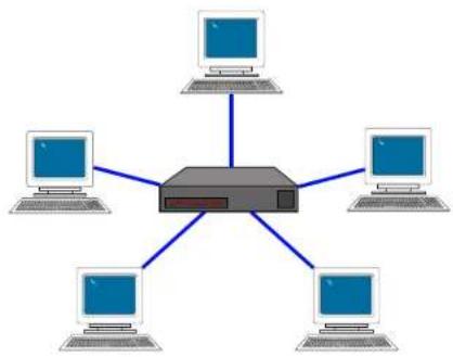
flowchart
graph TD
    A["Computer"] --> C["Switch"]
    B["Computer"] --> C["Switch"]
    D["Computer"] --> C["Switch"]
    E["Computer"] --> C["Switch"]
    F["Computer"] --> C["Switch"]
Figure 9.3 Star Topology

Figure 9.4 Multi-Star Topology
In System Architect, you create audio connections between sending devices (transmitters) and receiving devices (receivers). For example, a mixer could be a transmitter, and a power amp could be a receiver.
You assign each connection a Bundle number. The Bundle number indicates which devices are communicating with each other.
Also in System Architect, you address each connection as Multicast or Unicast. A Multicast (Broadcast) connection is from one transmitter to multiple receivers. A Unicast connection is from one transmitter to one receiver. For example, if you send a mixer's digital audio signal to several power amps, the signal would be Multicast. Unicast is most used on "switched" networks requiring more than 64 channels.
You specify a connection as Multicast or Unicast by the delivery address if you give it in System Architect. 255 and lower is Multicast (Broadcast); 256 and up is Unicast.
The "Receiver Count" monitor indicates how many devices are receiving the digital audio bundle. The "Active" indicator indicates whether the particular Bundle is being actively transmitted onto the network.
9.2.4 The Conductor
A CobraNet system is coordinated by one audio device in the network called the Conductor. It regulates the CobraNet digital audio traffic on the CobraNet network. That is, the Conductor is the master clock for the rest of the network.
You choose one device to be the network conductor based on a priority scheme. The Conductor indicator will light on the CobraNet device that is serving as the conductor.
The Conductor handles time-division multiplexing and clock recovery on the network. The Conductor periodically broadcasts a well-defined "beat" packet to all components to recover synchronous timing information. The "beat" also specifies which addresses can transmit at certain time slots within the "beat" period.
Each transmitting device is allowed to transmit in a given time-slot within the Conductor-controlled isochronous cycle time. The time-slot is deter mined by the assigned bundle priority. Higher bundle priorities receive lower-numbered positions and are transmitted first.
9.2.5 Switched Networks
A more complex CobraNet network can be built using Ethernet switches. Switches do not simply broadcast each and every packet to all nodes. Instead, they check each incoming data packet to determine its destination and (very quickly) transmit the data to only that destination port. This allows for more network data flow, more Bundles and more audio channels.
In effect, each network port in an audio component has 100MB of band width. The network can be as large as 100MB times the number of ports on the network.
Another advantage of switched networks is "full-duplex" connections between components. A full-duplex link allows simultaneous send and receive over the same Ethernet connection.
9 Appendix B: Setting Sensitivity for Best Gain Staging
Optimized system gain structure maximizes signal to noise within the system. Adjusting your amplifier to fit within an optimized system gain structure is accomplished by properly setting both the sensitivity and attenuation controls within the amplifier. I-Tech amplifiers offer 149 sensitivity and gain settings allowing very fine adjustment of the amplifier's gain and voltage sensitivity. The Appendix section of the I-Tech Application guide (online at www.crownaudie.com) provides charts with sensitivity in volts and gain in dB for each sensitivity/gain setting.
With other amplifiers, it is often necessary to apply attenuation in order to achieve the desired sound pressure level. Large amounts of attenuation are not necessary with I-Tech amplifiers and can, in fact, degrade performance. The attenuation adjustment should only be used for small (3 dB) or temporary adjustments in amplifier gain. Instead, set the sensitivity/gain of your I-Tech amplifier so that you can achieve the desired output with the attenuators at or near 0 dB.
Example: Suppose that you are using an I-19000HD with the sensitivity/gain set at 1.4V/37.1 dB. After optimizing the gain structure of the rest of your system you find that attenuating the amplifier by 10 dB produces the desired loudness. The same output level, with improved signal-to-noise ratio and headroom, can be achieved by using 0 dB of attenuation and by setting the amplifier sensitivity/gain to 5.81V/27.0 dB (37 dB - 10 dB = 27 dB).
Note: as indicated in the online appendix, the list of possible sensitivity settings is different for each position of the max input setting. If, while adjusting sensitivity/gain in your amplifier, you do not find the setting you need, try changing the status of the max input setting and search again.
10 Service
Crown amplifiers are quality units that rarely require servicing. Before returning your unit for service, please contact Crown Technical Support to verify the need for servicing.
This unit has very sophisticated circuitry which should only be serviced by a fully trained technician. This is one reason why each unit bears the following label:
CAUTION: To prevent electric shock, do not remove covers. No user serviceable parts inside. Refer servicing to a qualified technician.
Complete the Crown Audio Factory Service Information form, In the back of this manual, when returning a Crown product to the factory or authorized service center. The form must be included with your product inside the box or in a packing slip envelope securely attached to the outside of the shipping carton. Do not send this form separately.
Warranty is only valid within the country in which the product was purchased.
10.1 International and Canada Service
Service may be obtained from an authorized service center. (Contact your local Crown/Amcreon representative or our office for a list of authorized service centers.) To obtain service, simply present the bill of sale as proof of purchase along with the defective unit to an authorized service center. They will handle the necessary paperwork and repair.
Remember to transport your unit in the original factory pack.
10.2 US Service
Service may be obtained in one of two ways: from an authorized service center or from the factory. You may choose either. It is important that you have your copy of the bill of sale as your proof of purchase.
10.2.1 Service at a US Service Center
This method usually saves the most time and effort. Simply present your bill of sale along with the defective unit to an authorized service center to obtain service. They will handle the necessary paperwork and repair.
Remember to transport the unit in the original factory pack. A list of authorized service centers in your area can be obtained from Crown Factory Service, or online from http://www.crownaudio.com/support/servcent.htm.
10.2.2 Factory Service
Crown accepts no responsibility for non-serviceable product that is sent to us for factory repair. It is the owner's responsibility to ensure that their product is ser viceable prior to sending it to the factory. Serviceable product list is available at http://crownweb.crownintl.com/crownrna/. For more information, please contact us direct.
A Service Return Authorization (SRA) is required for product being sent to the factory for repair. An SRA can be completed online at www.crownaudio.com/support/factserv.htm. If you do not have access to the web, please call Crown's Customer Service at 574.294.8200 or 800.342.6939 extension 8205.
For warranty service, we will pay for ground shipping both ways in the United States. Contact Crown Customer Service to obtain prepaid shipping labels prior to sending the unit. Or, if you prefer, you may prepay the cost of shipping, and Crown will reimburse you. Send copies of the shipping receipts to Crown to receive reimbursement. Your repaired unit will be returned via UPS ground. Please contact us if other arrangements are required.
10.2.3 Factory Service Shipping Instructions:
-
Service Return Authorization (SRA) is required for product being sent to the factory for service. Please complete the SRA by going to www.crownaudio.com/support/factserv.htm. If you do not have access to our website, call 1.800.342 6939, extension 8205 and we'll create the SRA for you.
-
See packing instructions that follow.
-
Ship product to: CROWN AUDIO FACTORY SERVICE 1718 W MISHAWKA RD. ELKHART, IN 46517
-
Use a bold black marker and write the SRA number on three sides of the box.
- Record the SRA number for future reference. The SRA number can be used to check the repair status.
10.2.4 Packing Instructions
Important: These instructions must be followed. If they are not followed, Crown Audio, Inc. assumes no responsibility for damaged goods and/or accessories that are sent with your unit.
- Fill out and include the Crown Audio Factory Service Information sheet in the back of this manual.
- Do not ship any accessories (manuals, cords, hard ware, etc.) with your unit. These items are not needed to service your product. We will not be responsibility for these items.
- When shipping your Crown product, it is important that it has adequate protection. We recommend you use the original pack material when returning the product for repair. If you do not have the original box, please call Crown at 800.342.6939 or 574.294.8210 and order new pack material. See Instructions for "foam-in-place" shipping pack. (Do not ship your unit in a wood or metal cabinet.)
- If you provide your own shipping pack, the mini mum recommended requirements for materials are as follows:
a. 275 P.S.I. burst test, Double-Wall carton that allows for 2-inch solid Styrofoam on all six sides of unit or 3 inches of plastic bubble wrap on all six sides of unit.
b. Securely seal the package with an adequate carton scaling tape.
c. Do not use light boxes or "peanuts". Damage caused by poor packaging will not be covered under warranty.
Using your 'foam-in-place' shipping pack
Note: The foam-in-place packing is molded so that there is only one correct position for your product.
- Open carton and lift center cushion leaving both end-cushions in place.
- Carefully place your product with the product's front panel facing the same direction as arrows indicate.
- Reset center cushion down over top of product's chassis. The foam-in-place packing was molded to accommodate different chassis depth sizes. If your product's chassis does not completely fill the foam-in-place cavity, you may use a soft but solid packing material (such as paper or bubble wrap) behind the chassis.
- Enclose the completed Crown Audio Factory Service Information form (or securely attach it to the outside of carton) and re-seal the shipping pack with a sturdy carton sealing tape.
10.2.5 Estimate Approval
Approval of estimate must be given within 30 days after being notified by Crown Audio Inc. Units still in the pos session of Crown after 30 days of the estimate will become the property of Crown Audio Inc.
10.2.6 Payment of Non-Warranty Repairs
Payment on out-of-waranty repairs must be received within 30 days of the repair date. Units unclaimed after 30 days become the property of Crown Audio Inc.
If you have any questions, please contact Crown Factory Service.
Crown Factory Service
1718 W. Mishawaka Rd., Elkhart, Indiana 46517 U.S.A.
Telephone:
574.294.8200
800.342.6939 (North America)
Puerto Rico, and Virgin Islands only)
Facsimile:
574.294.8301 (Technical Support) 574.294.8124 (Factory Service)
Internet:
http://www.crownaudio.com
11 Warranty

UNITED STATES & CANADA
SUMMARY OF WARRANTY
Crown International, 1718 West Mishawaka Road, Elkhart, Indiana 48517-4095 U.S.A. warrants to you, the ORIGINAL PURCHASER and ANY SUB SEQUENT OWNER of each NEW Crown product, for a period of five (5) years from the date of purchase by the original purchaser (the "warranty period") that the new Crown product is free of defects in materials and workmanship. We further warrant the new Crown product regardless of the reason for failure, except as excluded in this Warranty.
Warranty is only valid within the country in which the product was purchased.
ITEMS EXCLUDED FROM THIS CROWN WARRANTY
This Crown Warranty is in effect only for failure of a new Crown product which occurred within the Warranty Period. It does not cover any product which has been damaged because of any intentional misuse, accident, negligence, or loss which is covered under any of your insurance contracts. This Crown Warranty also does not extend to the new Crown product if the serial number has been defaced, altered, or removed.
WHAT THE WARRANTOR WILL DO
We will remedy any defect, regardless of the reason for failure (except as excluded), by repair, replacement, or refund. We may not elect refund unless you agree, or unless we are unable to provide replacement, and repair is not practical or cannot be timely made. If a refund is elected, then you must make the defective or malfunctioning product available to us free and clear of all liens or other encumbrances. The refund will be equal to
the actual purchase price, not including interest, insurance, closing costs, and other finance charges less a reasonable depreciation on the product from the date of original purchase. War ranty work can only be performed at our authorized service centers or at the factory. Warranty work for some products can only be performed at our factory. We will remedy the defect and ship the product from the service center or our factory within a reasonable time after receipt of the defective product at our authorized service center or our factory. All expenses in remedying the defect, including surface shipping costs in the United States, will be borne by us. (You must bear the expense of shipping the product between any for eign country and the port of entry in the United States including the return shipment, and all taxes, duties, and other customs fees for such for eign shipments.)
HOW TO OBTAIN WARRANTY SERVICE
You must notify us of your need for warranty service within the warranty period. All components must be shipped in a factory pack, which, if needed, may be obtained from us free of charge. Corrective action will be taken within a reasonable time of the date of receipt of the defective product by us or our authorized service center. If the repairs made by us or our authorized service center are not satisfactory, notify us or our authorized service center immediately.
DISCLAIMER OF CONSEQUENTIAL AND INCIDENTAL DAMAGES
YOU ARE NOT ENTITLED TO RECOVER FROM US ANY INCIDENTAL DAMAGES RESULTING FROM ANY DEFECT IN THE NEW CROWN PRODUCT.
THIS INCLUDES ANY DAMAGE TO ANOTHER PRODUCT OR PRODUCTS RESULTING FROM SUCH A DEFECT. SOME STATES DO NOT ALLOW THE EXCLUSION OR LIMITATIONS OF INCIDENTAL OR CONSEQUENTIAL DAM AGES, SO THE ABOVE LIMITATION OR EXCLUSION MAY NOT APPLY TO YOU.
WARRANTY ALTERATIONS
No person has the authority to enlarge, amend, or modify this Crown Warranty. This Crown Warranty is not extended by the length of time which you are deprived of the use of the new Crown product. Repairs and replacement parts provided under the terms of this Crown Warranty shall carry only the unexpired portion of this Crown Warranty.
DESIGN CHANGES
We reserve the right to change the design of any product from time to time without notice and with no obligation to make corresponding changes in products previously manufactured.
LEGAL REMEDIES OF PURCHASER
THIS CROWN WARRANTY GIVES YOU SPECIFIC LEGAL RIGHTS, YOU MAY ALSO HAVE OTHER RIGHTS WHICH VARY FROM STATE TO STATE. No action to enforce this Crown Warranty shall be commenced after expiration of the warranty period.
THIS STATEMENT OF WARRANTY SUPERSEDES ANY OTHERS CONTAINED IN THIS MANUAL FOR CROWN PRODUCTS. 5/11
11 Warranty

WORLDWIDE EXCEPT USA & CANADA
SUMMARY OF WARRANTY
Crown International, 1718 West Mishawaka Road, Elkhart, Indiana 46517-4095 U.S.A. warrants to you, the SEQUENT PURCHASER and ANY SUB SEQUENT OWNER of each NEW Crown1 product, for a period of five (5) years from the date of pur chase by the original purchaser (the "warranty period") that the new Crown product is free of defects in materials and workmanship, and we further warrant the new Crown product regardless of the reason for failure, except as excluded in this Warranty.
Warranty is only valid within the country in which the product is purchased.
1 Note: If your unit bears the name "Amron," please substitute it for the name "Crown" in this warranty.
ITEMS EXCLUDED FROM THIS CROWN-WARRANTY
This Crown Warranty is in effect only for failure of a new Crown product which occurred within the Warranty Period. It does not cover any product which has been damaged because of any Intentional misuse, accident, negligence, or loss which is covered under any of your Insurance contracts. This Crown Warranty also does not extend to the new Crown product if the serial number has been delaced, altered, or removed.
WHAT THE WARRANTOR WILL DO
We will remedy any defect, regardless of the reason for failure (except as excluded), by repair, replacement, or refund. We may not effect refund unless you agree, or unless we are unable to provide replacement, and repair is not practical or cannot be timely made. If a refund is elected, then you must make the defective or malfunctioning product available to us free and clear of all liens or other encumbrances. The refund will be equal to the actual purchase price, not including interest, insurance, closing costs, and other finance charges less a reasonable depreciation on the product from the date of original purchase. Warranty work can only be performed at our authorized service centers. We will remedy the defect and ship the product from the service center within a reasonable time after receipt of the defect five product at our authorized service center.
HOW TO OBTAIN WARRANTY SERVICE
You must notify your local Crown importer of your need for warranty service within the warranty period. All components must be shipped in the original box. Corrective action will be taken within a reasonable time of the date of receipt of the defective product by our authorized service center. If the repairs made by our authorized service center are not satisfactory, notify our authorized service center immediately.
DISCLAIMER OF CONSEQUENTIAL AND INCIDENTAL DAMAGES
YOU ARE NOT ENTITLED TO RECOVER FROM US ANY INCIDENTAL DAMAGES RESULTING FROM ANY DEFECT IN THE NEW CROWN PRODUCT. THIS INCLUDES ANY DAMAGE TO ANOTHER PRODUCT OR PRODUCTS RESULTING FROM SUCH A DEFECT.
WARRANTY ALTERATIONS
No person has the authority to enlarge, amend, or modify this Crown Warranty. This Crown Warranty is not extended by the length of time which you are deprived of the use of the new Crown product. Repairs and replacement parts provided under the terms of this Crown Warranty shall carry only the unexpired portion of this Crown Warranty.
DESIGN CHANGES
We reserve the right to change the design of any product from time to time without notice and with no obligation to make corresponding changes in products previously manufactured.
LEGAL REMEDIES OF PURCHASER
No action to enforce this Crown Warranty shall be commenced after expiration of the warranty period. THIS STATEMENT OF WARRANTY SUPERSEDES ANY OTHERS CONTAINED IN THIS MANUAL FOR CROWN PRODUCTS. 5/11

crown®
by HARMAN
PRODUCT REGISTRATION
Crown Audio, Inc.
1718 W. Mishawaka Rd
Elkhart, IN 46517-9439
Phone: 574-294-8000
Fax: 574-294-8329
www.crownaudin.com
Online registration is also available at http://crownweb.crownintl.com/webregistration.
Warranty is only valid within the country in which the product is purchased.
When this form is used to register your product, it may be mailed or faxed.
Crown Audio, Inc.
1718 W Mishawaka Rd
Elkhart IN 46517
Fax: 574-294-8329
Please note that some information is required. Incomplete registrations will not be processed. * Indicates required information.
OWNER'S INFORMATION - PLEASE PRINT
* First name: ____ Middle initial: ____ * Last name: ____
Company:
* Mailing address:
* City: ____ * State: ____ * Zip Code: ____
* Country: ____ E-mail address: ____
* Phone # (include area code): ____ Fax #: ____
PRODUCT INFORMATION
* MODEL
e.g. IT8000, CDi1000, PCC160
* SERIAL #
e.g. 8000000000
* PURCHASE DATE
mo/day/yr

Product purchased from: *(Business/Individual) ____ Country: ____
Comments:
THIS PAGE INTENTIONALLY LEFT BLANK
Crown Audio Factory Service Information
Shipping Address: Crown Audio Factory Service, 1718 W. Mishawaka Rd., Elkhart, IN 46517
PLEASE PRINT CLEARLY
| SRA #:____(If sending product to Crown factory service.) | Model:____ | Serial Number:____ | Purchase Date:____ |
PRODUCT RETURN INFORMATION
| Individual or Business Name: | |||
| Phone #: | Fax #: | E-Mail: | |
| Street Address (please, no P.O. Boxes): | |||
| City: | State/Prov: | Postal Code: | Country: |
| Nature of problem: | |||
Other equipment in your system:
If warranty is expired, please provide method of payment. Proof of purchase may be required to validate warranty.
PAYMENT OPTIONS
| □ I have open account payment terms. Purchase order required. PO#: ________ □ COD |
| □ Credit Card (Information below is required; however if you do not want to provide this information at this time, we will contact you when your unit is repaired for the information.) |
| Credit card information: |
| Type of credit card: □ MasterCard □ Visa □ American Express □ Discover |
| Type of credit card account: □ Personal/Consumer □ Business/Corporate |
| Card #: ____ Exp. date: ____ * Card ID #: ____ |
| * Card ID # is located on the back of the card following the credit card #, in the signature area. On American Express, it may be located on the front of the card. This number is required to process the charge to your account. If you do not want to provide it at this time, we will call you to obtain this number when the repair of your unit is complete. |
| Name on credit card: ________ |
| Billing address of credit card: ________ |

CROWN®
by HARMAN
- Important Safety Instructions
- WATCH FOR THESE SYMBOLS:
- REGARDEZ CES SYMBOLES:
- IMPORTANT
- FCC COMPLIANCE NOTICE
- Table of Contents
- Welcome
- Features
- How to Use This Manual
- Setup
- Unpack and Install Your Amplifier
- MAGNETIC FIELD
- Connecting to AC Mains
- Wire Inputs and Outputs
- Wiring basics
- Choose Input Wire and Connectors
- Choose Output Wire and Connectors
- CAUTION – SHOCK HAZARD: Potentially lethal voltages exist at the output connectors when the amplifier is turned on and is passing a signal.
- Stereo Mode Wiring
- IMPORTANT: Turn off the amplifier and unplug its power cord.
- Operation Manual
- Bridge-Mono Mode
- IMPORTANT: Turn off the amplifier and unplug its power cord.
- Operation
- Protecting Your Speakers
- Startup Procedure
- Precautions
- Front Panel Controls and Indicators
- Many of these functions can be disabled using Blackout Mode (a selection in the Advanced Menu, Section 4.2.3).
- Cooling Vents
- LCD Control Screen
- Power Switch
- USB 2.0 Connector
- Fault Indicator
- Thermal Indicator
- Clip Indicator
- Level Controls (Encoders)
- Menu/Exit Button
- Prev Button
- Next Button
- Signal Indicators
- Ready Indicator
- Power Indicator
- Data Indicator
- P Bridge Mode Indicator
- Fans
- ANALOG INPUTS SECTION
- Balanced Analog XLR Inputs
- Balanced Analog XLR Loop-Through Outputs
- OUTPUTS SECTION
- 4-Pole Speakon ® Output Connectors
- Binding Post Output Jacks
- Power Cord Connector
- Reset Switch/Circuit Breaker
- MAC Address
- Preset Indicator
- Reset Button
- Data Indicator
- DIGITAL INPUTS SECTION
- AES/EBU Digital Input
- M AES/EBU Digital Loop-through Output
- NETWORKING SECTION
- Link/Act Indicator
- Network Connector
- Cond Indicator
- Advanced Operation
- Navigating the LCD Control Screen
- Introduction
- MENU TREE
- ADVANCED MENU Next
- MONITOR MENU
- Next
- Exit
- ALERT MENU
- NETWORKING MENU
- COBRANET MENU
- Operation Examples
- Operation Example 1
- Menu/Exit.
- Press Next
- Press Menu/Exit
- Operation Example 2
- Operation Example 3
- Basic Selections
- Attenuation and Bar Meters
- Mute/Unmute (in the Attenuation screen)
- Front Panel Lockout (in the Attenuation screen)
- ADVANCED MENU
- MONITOR MENU
- ALERT MENU
- NETWORKING MENU
- COBRANET MENU
- Presets
- Introduction
- User Presets
- Downloadable Presets
- File Transfer Via the USB Port
- How to transfer a file from a USB flash drive to the amplifier:
- How to transfer a file from the amplifier to a USB flash drive:
- List of Pop-Up Boxes and Descriptions
- Digital Audio Options (AES/EBU)
- Networking the Amplifier
- Network Troubleshooter
- Select Network Card
- Software-Controllable Onboard DSP
- Amplifier DSP Selection Screen
- Amplifier Mode
- Input Level, Mute, Link, Level Meters, and Indicators
- Input Signal Level Meter
- Output Signal Level Meter
- Indicators
- Input Signal Router
- • Digital with Analog Backup
- • Digital with Analog Override
- Source Configuration
- CobraNet Advanced Settings
- Input Signal Compressor
- Input EQ and Output EQ
- Crossover Filters
- LevelMax Suite
- Peak Voltage Limiter
- Average Power Limiter
- Transducer Thermal Limiting
- Front Panel Security
- Amplifier Settings
- Error Reporting
- Continuous Load Monitoring
- Amplifier Information
- Apply to Others
- Delay (Latency)
- Preset Manager
- Signal Generator
- Fixed-Gain Mode in the I-Tech HD
- Troubleshooting
- CONDITION: Power indicator is off and power switch is not illuminated.
- CONDITION: Thermal indicator is on.
- CONDITION: Power Indicator is off and power switch is illuminated.
- CONDITION: Fault indicator is flashing.
- CONDITION: Power indicator is flashing.
- Specifications
- AC Power Draw and Thermal Dissipation
- I-Tech 5000HD AC Current Draw and Thermal Dissipation:
- Advanced Features
- Protection Systems
- Thermal Level Control (TLC)
- Circuit Breaker
- Global Switching Power Sup ply with PFC
- 3rd Generation Class | Circuitry
- Color-Coded Rear Overlay
- Appendix A: Network and CobraNet Basics
- HiQnet Networks
- Network Addresses
- 00-0A-40-00-DC-2F
- 192.168.0.1
- IP Router
- A Closer Look at CobraNet
- Fast Ethernet
- Audio Specs
- Bundles and Audio Channels
- The Conductor
- Switched Networks
- Appendix B: Setting Sensitivity for Best Gain Staging
- Service
- CAUTION: To prevent electric shock, do not remove covers. No user serviceable parts inside. Refer servicing to a qualified technician.
- International and Canada Service
- US Service
- Service at a US Service Center
- Factory Service
- Factory Service Shipping Instructions:
- Packing Instructions
- Using your 'foam-in-place' shipping pack
- Estimate Approval
- Payment of Non-Warranty Repairs
- Crown Factory Service
- Telephone:
- Facsimile:
- Internet:
- Warranty
- UNITED STATES & CANADA
- SUMMARY OF WARRANTY
- ITEMS EXCLUDED FROM THIS CROWN WARRANTY
- WHAT THE WARRANTOR WILL DO
- HOW TO OBTAIN WARRANTY SERVICE
- DISCLAIMER OF CONSEQUENTIAL AND INCIDENTAL DAMAGES
- WARRANTY ALTERATIONS
- DESIGN CHANGES
- LEGAL REMEDIES OF PURCHASER
- WORLDWIDE EXCEPT USA & CANADA
- ITEMS EXCLUDED FROM THIS CROWN-WARRANTY
- PRODUCT REGISTRATION
- OWNER'S INFORMATION - PLEASE PRINT
- PRODUCT INFORMATION
- Crown Audio Factory Service Information
Brand : CROWN
Model : I-Tech HD 9000HD
Category : Radio