ZSR2104WE - Router Zonet - Free user manual and instructions
Find the device manual for free ZSR2104WE Zonet in PDF.


| Product Type | Wireless 125Mbps AP Router |
| Model | ZSR2104WE |
| Brand | Zonet |
| Maximum Wireless Speed | 125 Mbps (AfterBurner mode) |
| Wireless Standards | IEEE 802.11b/g |
| Frequency Band | 2.4 GHz |
| Number of LAN Ports | 4 (10/100 Mbps) |
| Number of WAN Ports | 1 (10/100 Mbps) |
| Power Supply | DC 5V |
| Default IP Address | 192.168.1.1 |
| Default Subnet Mask | 255.255.255.0 |
| Default SSID | wlan-g |
| Default Channel | 6 |
| Security Modes | WEP, WPA-PSK (TKIP/AES), WPA-RADIUS |
| DHCP Server | Yes (configurable) |
| Virtual Server / Port Forwarding | Yes |
| Dynamic DNS | DynDNS.org, TZO.com |
| VPN Pass-through | IPSec, L2TP, PPTP |
| Web Filters | Proxy, Java, ActiveX, Cookies |
| Firmware Upgrade | Yes (via web interface) |
| SNMP | Yes (v2c) |
| Operating Temperature | +5 to +40 °C |
| Package Contents | AP Router, Installation CD with manual, Quick Installation Guide, Power Supply, Ethernet Cable |
Frequently Asked Questions - ZSR2104WE Zonet
User questions about ZSR2104WE Zonet
0 question about this device. Answer the ones you know or ask your own.
Ask a new question about this device
Download the instructions for your Router in PDF format for free! Find your manual ZSR2104WE - Zonet and take your electronic device back in hand. On this page are published all the documents necessary for the use of your device. ZSR2104WE by Zonet.
USER MANUAL ZSR2104WE Zonet
Wireless 125Mbps AP Router User's Manual
Contents
- Introduction......2
- SafetyNotification....3
3.Hardware Installation....4 - Web Management Settings......6
4.1.PrimarySetup....7 ( how to set up 125Mbps mode )....12
4.2.Security....13
4.3.System....19
4.4.DHCPServer....23
4.5.SNMPInfo....25
4.6.Status....27
4.7.AdvancedWireless....29
4.8.AccessFilters....33
4.9.VirtualServer....36
4.10.RoutingTable....39
4.11.DynamicDNS....42
- Troubleshooting....44
1. Introduction
Thank you for purchasing this Wireless 125Mbps AP Router.
This user guide will assist you with the installation procedure.
The package you have received should contain the following items:
---AP Router Wireless 125Mbps AP Router
---Installation CD (with manual inside)
---Quick Installation Guide
---Power Supply / Cord
---Ethernet Cable
Note: if anything is missing, please contact your vendor
2. Safety Notification
Your Wireless AP Router should be placed in a safe and secure location. To ensure proper operation, please keep the unit away from water and other damaging elements. Please read the user manual thoroughly before you install the device. The device should only be repaired by authorized and qualified personnel.
---Please do not try to open or repair the device yourself.
---Do not place the device in a damp or humid location, i.e. a bathroom.
---The device should be placed in a sheltered and non-slip location within a temperature range of +5 to +40 Celsius degree.
---Please do not expose the device to direct sunlight or other heat sources. The housing and electronic components may be damaged by direct sunlight or heat sources.
3. Hardware Installation
Front Panel
The front panel provides LED's for device status. Refer to the following table for the meaning of each feature.
| LED STAT | US Description | ||
| PWR/STAT | Off No power | ||
| Red On | Red On | 1. Power on 2. Reset to default 3.Firmware upgrade (first 1 minute) | |
| Red Blink | 1. System up 2. Power on 3.Firmware upgrade | ||
| Red Blink | |||
| LAN | Off no Ethernet link detected | ||
| Green On | Green ON | 10/100Mbps Fast Ethernet linkdetected. No activity. | |
| Green Blink | Indicates data traffic on the 10/100Mbps LAN | ||
| WAN Orange | Blink | Indicates data traffic on the 10/100Mbps LAN | |
| G Yellow | Blink | Indicates the device is linking oractive data through wireless links | |
Rear Panel
The rear panel features 4 LAN ports, 1 WAN port and Reset button. Refer to the following table for the meaning of each feature.
| Power (DC 5v) | Used to connect to the power outlet. Only use the power adapter provided with the device. Use of an unauthorized power adapter may cause damage to your device and violate your warranty. |
| Reset | Press the Reset Button for approximately ten seconds, all configurations will set to factory default settings. |
| LAN | The RJ-45 Ethernet ports used to connect your PC, hub, switch or Ethernet network. |
| WAN | The RJ-45 Ethernet port labeled WAN is used to connect your AP Router to your xDSL or Cable modem. |
AP Router Default Settings
The default settings are shown following.
| User | |
| Password admin | |
| AP Router IP Address | 192.168.1.1 |
| AP Router Subnet Mask | 255.255.255.0 |
| RF ESSID wlan-g | |
| 11g RF Channel 6 | |
| Mode | Disabled11b+g11g onlyAfterBurner |
| Encryption Disabled | |
| DHCP client Enabled |
4 Web Management Settings
START UP & LOGIN
In order to configure the Wireless 11g AP Router, you must use your web browser and manually input http://192.168.1.1 into the Address box and press Enter. The Main Page will appear.

In order to configure the Wireless 125Mbps AP Router, you must input the password into the Password box and leave blank on the User Name box. The default password is "admin".
Once you have logged-in as administrator, it is a good idea to change the administrator password to ensure a secure protection to the Wireless 125Mbps AP Router. The Security Settings section described later in this manual describes how to change the password.
Once you have input the correct password and logged-in, the screen will change to the Setup page screen.
WARNING : TURN ON POWER SUPPLY
Quick power cycle can caused system corruption. When power on, be careful not to shut down in about 5 seconds, because data is writing to the flash.
4.1. Primary Setup
Primary Setup
This screen contains all of the Router's basic setup functions.
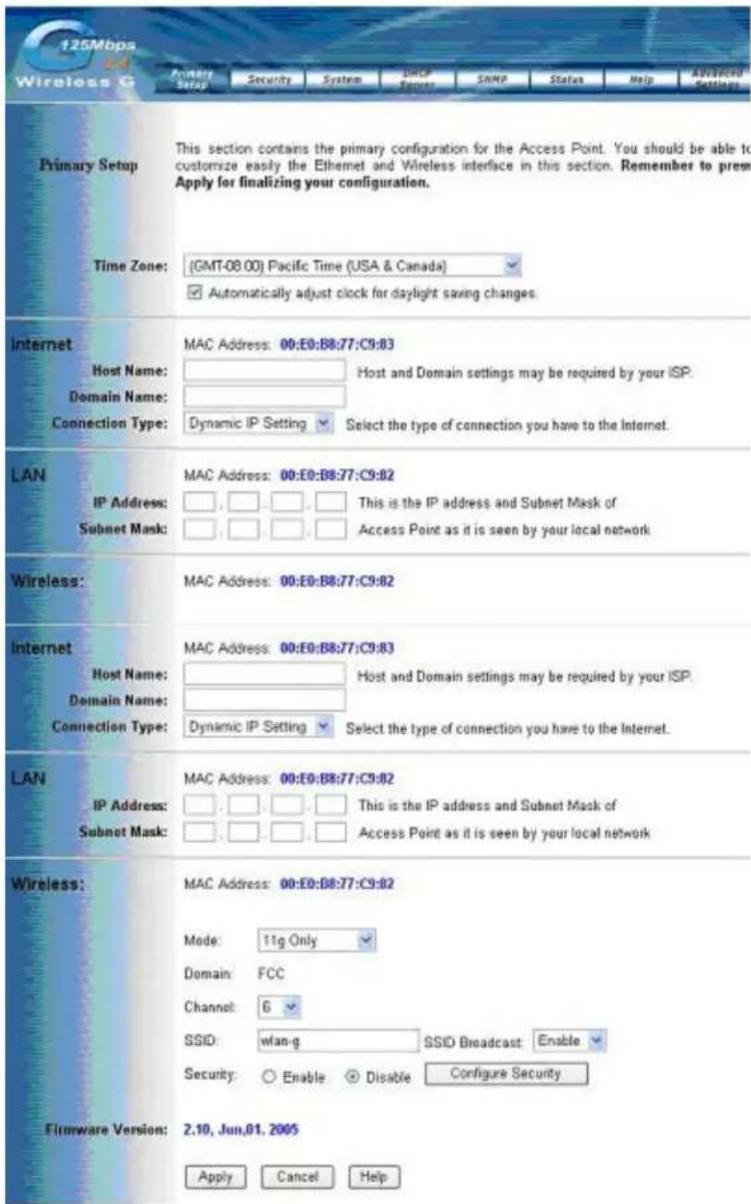
Most users will be able to configure the AP Router and get it working properly using the settings on this screen. Some Internet Service Providers (ISPs) will require that you enter AP Router Wireless 802.11g AP Router specific information, such as User Name, Password, IP Address, Default Gateway Address, or DNS IP Address. This information can be obtained from your ISP, if required.
MAKE CORRECT NETWORK SETTINGS OF YOUR COMPUTER
To change the configuration, use Internet Explorer (IE) or Netscape
Communicator to connect the WEB management 192.168.1.1.
WAN:
Host Name:
This entry is necessary for some ISPs and can be provided by them.
Domain Name:
This entry is necessary for some ISPs and can be provided by them.
Configuration Type:
The Router supports four connection types:
Dynamic IP Setting:
Static IP Address
PPPoE (Point-to-Point Protocol over Ethernet)
PPTP (Point-to-Point Tunneling Protocol)
Dynamic

Static IP Address

PPPoE

PPTP

These types can be selected from the drop-down menu next to Internet Connection. The information required and available features will differ depending on what kind of connection type you select.
Some descriptions of this information are included here:
Internet IP Address and Subnet Mask
This is the Router's IP Address and Subnet Mask as seen by external users on the Internet (including your ISP). If your Internet connection requires a static IP address, then your ISP will provide you with a Static IP Address and Subnet Mask.
Default Gateway
Your ISP will provide you with the Gateway IP Address.
DNS (Domain Name Server) IP Address
Your ISP will provide you with at least one DNS IP Address.
User Name and Password
Enter the User Name and Password you use when logging onto your ISP through a PPPoE or PPTP connection.
Connect on Demand
You can configure the Router to disconnect your Internet connection after a specified period of inactivity (Max Idle Time). If your Internet connection has been terminated due to inactivity, Connect on Demand enables the Router to automatically re-establish your connection as soon as you attempt to access the Internet again.
If you wish to activate Connect on Demand, click the radio button. If you want your Internet connection to remain active at all times, enter 0 in the 125Mbps AP Router max Idle Time field. Otherwise, enter the number of minutes you want to have elapsed before your Internet connection terminates.
Keep Alive Option
This option keeps you connected to the Internet indefinitely, even when your connection sits idle. To use this option, click the radio button next to Keep Alive. The default Redial
Period is 30 seconds (in other words, the Router will check the Internet connection every 30 seconds).
LAN IP Address and Subnet Mask:
This is the Router's IP Address and Subnet Mask as seen on the internal LAN. The default value is 192.168.1.1 for IP Address and 255.255.255.0 for Subnet Mask.
Wireless:
This section provide the Wireless Network settings for your WLAN
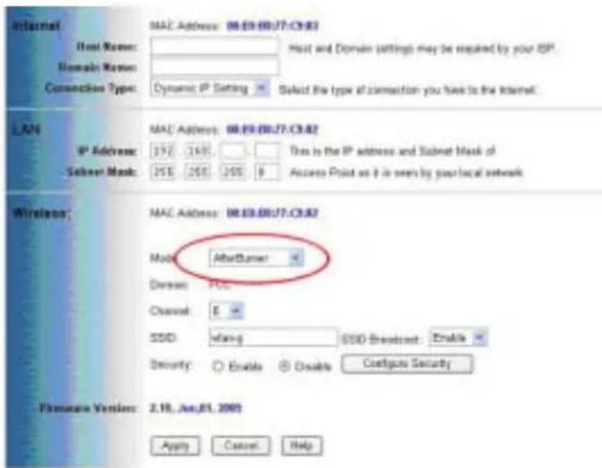
Mode:
This unit supports 3 wireless mode - 11b+g, 11g Only and AfterBurner (turbo mode).
Caution : In case to reach the 125 Mbps turbo mode speed , user have to use the device which supported 125 Mbps technology
SSID:
The service set identifier (SSID) or network name. It is case sensitive and must not exceed 32 characters, which may be any keyboard character. You shall have selected the same SSID for all the APs that will be communicating with mobile wireless stations.
Domain:
The displaying information is related with each domain regulation.
Channel:
Select the appropriate channel from the list provided to correspond with your network settings. You shall assign a different channel for each AP to avoid signal interference.
4.2 Security:
There are 3 types of security to be selected. To secure your Wireless Networks, it's strongly recommended to enable this feature.
WEP / WPA Preshared Key / WPA Radius
select the "enable" to enter "configure security" screen

then you can see WEP / Preshared Key / WPA Radius mode
WEP:

Make sure that all wireless devices on your network are using the same encryption level and key. WEP keys must consist of the letters "A" through "F" and the numbers "0" through "9."
WPA-Preshared key

There are two encryption options for WPA Pre-Shared Key, TKIP and AES. TKIP stands for Temporal Key Integrity Protocol. TKIP utilizes a stronger encryption method and incorporates Message Integrity Code (MIC) to provide protection against hackers. AES stands for Advanced Encryption System, which utilizes a symmetric 128-Bit block data encryption.
To use WPA Pre-Shared Key, enter a password in the WPA Shared Key field between 8 and 63 characters long. You may also enter a Group Key Renewal Interval time between 0 and 99,999 seconds.
| WPA Algorithms Please choose your algorithms method. You can select between TKIP or AES. | |
| WPA Shared Key Please input the Pre-Shared Key. The key should be 8 characters or 63 characters in alphanumeric. | |
| Group Key Renewal Please input the period of renewal time. The default selection is 300 seconds. |
Important Notice
In order to make right use of WPA, please ensure that your current Wireless Adapter's driver, and Wireless Utility can support it, WPA needs 802.1x authentication (when RADIUS mode is chosen), though the Operating System must also support 802.1x protocol. For Microsoft's OS family, only Windows XP has incorporated this by default. The rest of the OS must installed 3er party's client software such as Funk Odyssey.
WPA RADIUS

WPA RADIUS uses an external RADIUS server to perform user authentication. To use WPA RADIUS, enter the IP address of the RADIUS server, the RADIUS Port (default is 1812) and the shared secret from the RADIUS server.
| WPA Algorithms Please choose your algorithms method. You can select between TKIP or AES. | |
| Radius Server Address Please input your RADIUS Server IP address. | |
| RADIUS Server Port Please input the Authentication port of your RADIUS server. The default port being used is 1812 | |
| RADIUS Shared Key The RADIUS server will accept the authentication if both Shared Key matched. | |
| Group Key Renewal Please input the period of renewal time. The default selection is 300 seconds. |

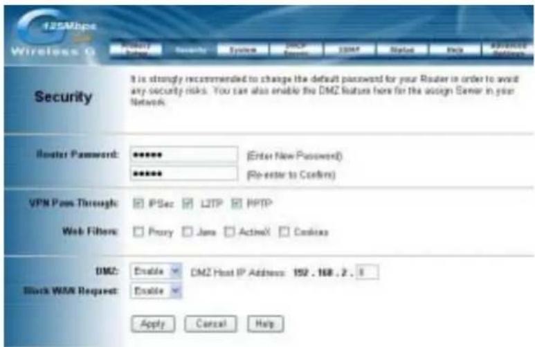
Router Password:
Changing the password for the AP Router is as easy as typing the password into the Enter New Password field. Then, type it again into the Re-enter to confirm.
* Click the Apply button to save the setting.
Use the default password when you first open the configuration pages, after you have configured these settings, you should set a new password for the Router (using the Security screen). This will increase security, protecting the Router from unauthorized changes.
VPN Pass-Through:
Virtual Private Networking (VPN) is typically used for work-related networking. For VPN tunnels, the Router supports IPSec Pass-Through, L2TP Pass-Through, and PPTP Pass-Through.
- IPSec - Internet Protocol Security (IPSec) is a suite of protocols used to implement secure exchange of packets at the IP layer. To allow IPSec tunnels to pass through the Router, IPSec Pass-Through is enabled by default. To disable IPSec Pass-Through, uncheck the box next to IPSec.
- L2TP - Layer 2 Tunneling Protocol is a protocol used to tunnel Point-to-Point Protocol (PPP) over the Internet. To allow L2TP tunnels to pass through the Router, L2TP Pass-Through is enabled by default. To disable L2TP Pass-Through, uncheck the box next to L2TP.
- PPTP - Point-to-Point Tunneling Protocol is the method used to enable VPN sessions to a Windows NT 4.0 or 2000 server. To allow PPTP tunnels to pass
through the Router, PPTP
Pass-Through is enabled by default. To disable PPTP Pass-Through, uncheck the box next to PPTP.
Web Filters: Using the Web Filters feature, you may enable up to four different filters.
- Proxy - Use of WAN proxy servers may compromise network security. Denying Proxy will disable access to any WAN proxy servers. To enable proxy filtering, click the box next to Proxy.
- Java - Java is a programming language for websites. If you deny Java, you run the risk of not having access to Internet sites created using this programming language. To enable Java filtering, click the box next to Java.
- ActiveX - ActiveX is a programming language for websites. If you deny ActiveX, you run the risk of not having access to Internet sites created using this programming language. To enable ActiveX filtering, click the box next to ActiveX.
- Cookies - A cookie is data stored on your PC and used by Internet sites when you interact with them. To enable cookie filtering, click the box next to Cookies.
DMZ:
The DMZ hosting feature allows one local user to be exposed to the Internet for use of a special-purpose service such as Internet gaming or videoconferencing. DMZ hosting forwards all the ports at the same time to one PC. The Port Forwarding feature is more secure because it only opens the ports you want to have opened, while DMZ hosting opens all the ports of one computer, exposing the computer so the Internet can see it.
Any PC whose port is being forwarded must have its DHCP client function disabled and should have a new static IP address assigned to it because its IP address may change when using the DHCP function.
- To expose one PC, select Enable.
- Enter the computer's IP address in the DMZ Host IP Address field.
- Click the Apply button.
Block WAN ICMP Request: By enabling the Block WAN Request feature, you can prevent your network from being "pinged," or detected, by other Internet users. The Block WAN Request feature also reinforces your network security by hiding your network ports. Both functions of the Block WAN Request feature make it more difficult for outside users to work their way into your network. This feature is enabled by default. Select Disable to disable this feature.
* Check all the settings and click Apply to save them.
4.3. System
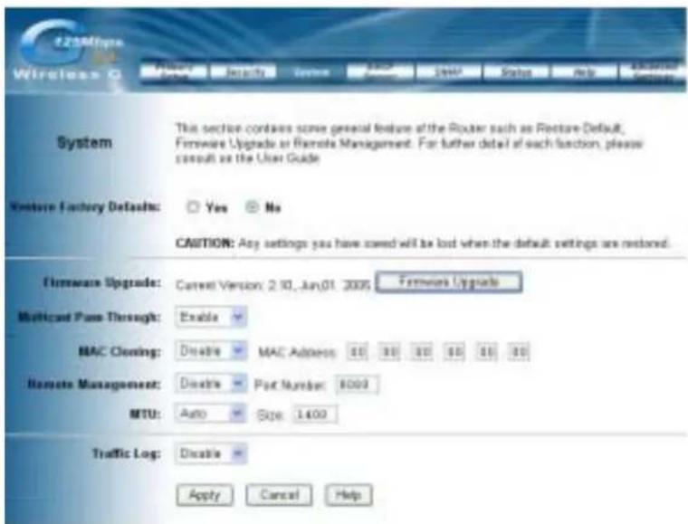
Restore Factory Defaults: Click the Yes button to reset all configuration settings to factory default values. Note: Any settings you have saved will be lost when the default settings are restored. Click the No button to disable the Restore Factory Defaults feature.
Click the Apply button to save the setting.
Firmware Upgrade: Click the Upgrade button to load new firmware onto the Router. If the Router is not experiencing difficulties, then there is no need to download a more recent firmware version, unless that version has a new feature that you want to use.
Note: When you upgrade the Router's firmware, you may lose its configuration settings, so make sure you write down the Router's settings before you upgrade its firmware.
To upgrade the Router's firmware:
- Download the firmware upgrade file from the internet.
- Extract the firmware upgrade file.
-
Click the Upgrade button.
-
On the Firmware Upgrade screen, click the Browse button to find the firmware upgrade file.

- Double-click the firmware upgrade file.
- Click the Upgrade button, and follow the on-screen instructions.
Note: Do not power off the Router or press the Reset button while the firmware is being upgraded.
Multicast Pass-Through: IP Multicasting occurs when a signal data transmission is sent to multiple recipients at the same time. Using the Multicast Pass-Through feature, the Router allows IP multicast packets to be forwarded to the appropriate computers. Keep the default setting, Enable, to support the feature, or select Disable to disable it.
MAC Cloning: The Router's MAC address is a 12-digit code assigned to a unique piece of hardware for identification. Some ISPs require that you register the MAC address of your network card/adapter, which was connected to your cable or DSL modem during installation. If your ISP requires MAC address registration, find your adapter's MAC address by following the instructions for your PC's operating system.
For Windows 98 and Millennium:
- Click the Start button, and select Run.
- Type winipcfg in the field provided, and press the OK key.
- Select the Ethernet adapter you are using.
- Click More Info.
- Write down your adapter's MAC address.
For Windows 2000 and XP:
- Click the Star button, and select Run.
- Type cmd in the field provided, and press the OK key.
- At the command prompt, run ipconfig /all, and look at your adapter's physical address.
- Write down your adapter's MAC address.
To clone your network adapter's MAC address onto the Router and avoid calling your ISP to change the registered MAC address, follow these instructions.
- Select Enable.
- Enter your adapter's MAC address in the MAC Address field.
- Click the Apply button
To disable MAC address cloning, keep the default setting, Disable.
Remote Management:
This feature allows you to manage your Router from a remote location, via the Internet. To disable this feature, keep the default setting, Disable. To enable this feature, select
Enable, and use the specified port (default is 8080) on your PC to remotely manage the Router. You Must also change the Router's default password to one of your own, if you haven't already. A unique password will increase security.
To remotely manage the Router, enter http://xxx.xxx.xxx.xxx:8080 (the x's represent the Router's Internet IP address, and 8080 represents the specified port) in your web browser's address field. You will be asked for the Router's password. After successfully entering the password, you will be able to access the Router's web-based utility.
Note: If the Remote Management feature is enabled, anyone who knows the Router's Internet IP address and password will be able to alter the Router's settings.
MTU: MTU is the Maximum Transmission Unit. It specifies the largest packet size permitted for Internet transmission. Keep the default setting, Auto, to have the Router select the best MTU for your Internet connection, To specify a MTU size, select Manual, and enter the value desired (default is 1400). You should leave this value in the 1200 to 1500 range.
Traffic Log: The Router can keep logs of all incoming or outgoing traffic for your Internet connection. This feature is disabled by default. To keep activity logs, select Enable.
To keep a permanent record of activity logs as a file on your PC's hard drive, Log
viewer software must be used. In the Send Log to field, enter the fixed IP address of the PC running the Log viewer software. The Router will send updated logs to that PC.
To see a temporary log of the Router's most recent incoming traffic, click the Incoming Access Log button. To see a temporary log of the Router's most recent outgoing traffic, click the Outgoing Access Log button.
Click the Apply button to save the setting.
4.4. DHCP Server

The DHCP Server screen allows you to configure the settings for the Router's Dynamic Host Configuration Protocol (DHCP) server function. The Router can be used as a DHCP server for your network. A DHCP server automatically assigns an IP address to each computer on your network. If you choose to enable the Router's DHCP server option, you must configure your entire network PCs to connect to a DHCP server, the Router.
If you disable the Router's DHCP server function, you must configure the IP Address, Subnet Mask, and DNS for each network computer (note that each IP Address must be unique).
DHCP Server: Select the Enable option to enable the Router's DHCP server option. If you already have a DHCP server on your network or you do not want a DHCP server, then select Disable from the options.
Starting IP Address: Enter a numerical value for the DHCP server to start with when issuing IP addresses. Because the Router's default IP address is 192.168.1.1, the Starting IP Address must be 192.168.1.2 or greater, but smaller
than192.168.5.253. The default Starting IP Address is 192.168.1.100.
Maximum Number of DHCP Users: Enter the maximum number of PCs that you want the DHCP server to assign IP addresses to. The absolute maximum is 253 - possible if 192.168.1.1 is your starting IP address. The default is 50.
Client Lease Time: The Client Lease Time is the amount of time a network user will be allowed connection to the Router with their current dynamic IP address. Enter the amount of time, in minutes, that the user will be "leased" this dynamic IP address. The default is 0 minutes, which means one day.
Static DNS 1-3: The Domain Name System (DNS) is how the Internet translates domain or website names into Internet addresses or URLs. Your ISP will provide you with at least one DNS Server IP Address. If you wish to utilize another, enter that IP Address in one of these fields. You can enter up to three DNS Server IP Addresses here. The Router will utilize these for quicker access to functioning DNS servers.
WINS: The Windows Internet Naming Service (WINS) manages each PC's interaction with the Internet. If you use a WINS server, enter that server's IP Address here. Otherwise, leave this blank.
Currently Assigned: Click the DHCP Clients Table button to see a list of PCs assigned IP addresses by the Router. For each PC, the list shows the client hostname, MAC address, IP address, and the amount of DHCP client lease time left. Click the Refresh button to display the most current information.
* Click Apply to save your settings.
4.5. SNMP
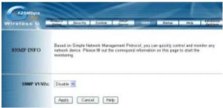
SNMP: The SNMP INFO screen allows you to customize the Simple Network Management Protocol (SNMP) settings. SNMP is a popular network monitoring and management protocol.
| SNMPv2c | To enable the SNMP support feature, select Enable. Otherwise, select Disable. | |
| Identification | Contact In the contact field, enter contact information for the Router. | |
| Unit Name and Description | In the Unit Name and Description field, enter the name of the Router. | |
| Physical Location | In the Physical Location field, specify the area or location where the Router resides. | |
| SNMP Community | public You may change the SNMP Community's name from its default, public. Then configure the community's access as either Read-Only or Read-Write. | |
| private You may change the SNMP Community's name from its default, public. Then configure the community's access as either Read-Only or Read-Write. | ||
Click Apply to save your settings.
4.6. Status
| 125Mbps Wireless G | Primary Select | Security | System | DHCP Server | SNMP | Status | Help | Advanced Settings |
| Status | This section contains a summary of the system. Please note that the information will be updated and displayed automatically every 10 seconds. | |||||||
| Firmware Version: | 2.10, Jun,01, 2005 | |||||||
| Current Time: | Thu Jan 1 00:59:04 1970 | |||||||
| Host Name: | ||||||||
| Domain Name: | zonet.com.tw | |||||||
| LAN | MAC Address: 00:E0:B8:77:C9:82 | |||||||
| IP Address: 192.168.1.1 Subnet Mask: 255.255.255.0 DHCP server: Enable | ||||||||
| Wireless | MAC Address: 00:E0:B8:77:C9:82 | |||||||
| Mode: 11b+g Channel: G SSID: wlan-g Encryption Function: Disabled | ||||||||

This screen displays the Wireless Router's current status and settings. This information is read-only.
This page will auto re-flash every 5 seconds to keep most update information.
Host Name: The Host Name is the name of the Router. This entry is necessary for some ISPs.
Domain Name: The Domain Name is the name of the Router's domain. This entry is necessary for some ISPs.
WAN IP Release: Click the WAN IP Release button to delete the Router's current Internet IP address.
WAN IP Renew: Click the WAN IP Renew button to get a new Internet IP address for the Router.
*Click the Refresh button to refresh the Router's status and settings.
4.7. Advanced Wireless
Wireless MAC Filters:
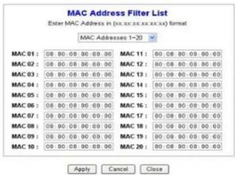
This function allows administrator to have access control by enter MAC address of client stations. When Enable this function, two new options will show up.

Depend on the filtering propose, it can be selected to Prevent or Permit.
Click on Edit MAC Filter List to add the client stations MAC list.
The table could store up to 40 different MAC addresses. Please follow the format that it required when an address is input.
Authentication Type:
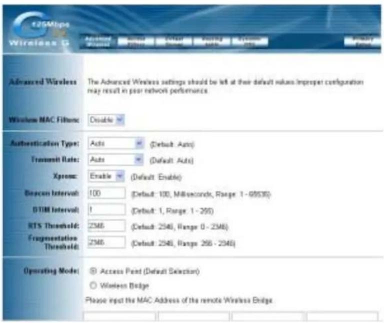

Auto:
Auto is the default authentication algorithm. It will change its authentication type
automatically to fulfill client's requirement.
Open System:
Open System authentication is not required to be successful while a client may decline to authenticate with any particular other client.
Shared Key:
Shared Key is only available if the WEP option is implemented. Shared Key authentication supports authentication of clients as either a member of those who know a shared secret key or a member of those who do not. IEEE 802.11 Shared Key authentication accomplishes this without the need to transmit the secret key in clear. Requiring the use of the WEP privacy mechanism.
Transmission Rate:
The rate of data transmission should be set depending on the speed of your wireless network. You can select from a range of transmission speeds, or you can select AUTO to have the Router automatically use the fastest possible data rate and enable the Auto-Fallback feature. Auto-Fallback will negotiate the best possible connection speed between the Router and a wireless client. The default setting is AUTO.
Xpress:
This is another wireless turbo mode. If wireless network card can support such turbo mode, then suggest to enable this function for enhance your WLAN performance.
DTIM Interval:
This value indicates the interval of the Delivery Traffic Indication Message (DTIM). A DTIM field is a countdown field informing clients of the next window for listening to broadcast and multicast messages. When the Access Point has buffered broadcast or multicast messages for associated clients, it sends the next DTIM with a DTIM Interval value.
Access Point Clients hear the beacons and awaken to receive the broadcast and multicast messages.
Beacon Interval:
The Beacon Interval value indicates the frequency interval of the beacon. Enter a value between 20 and 1000. A beacon is a packet broadcast by the Router to synchronize the wireless network. The default value is 100. User's Guide 22
RTS Threshold:
This value should remain at its default setting of 2346. Should you encounter inconsistent data flow, only minor modifications are recommended. If a network packet is smaller than the preset RTS threshold size, the RTS/CTS mechanism will not be enabled. The Router sends Request to Send (RTS) frames to a particular receiving station and negotiates the sending of a data frame. After
receiving an RTS, the wireless station responds with a Clear to Send (CTS) frame to acknowledge the right to begin transmission.
Fragmentation Threshold:
This value specifies the maximum size for a packet before data is fragmented into multiple packets. It should remain at its default setting of 2346. If you experience a high packet error rate, you may slightly increase the Fragmentation Threshold. Setting the Fragmentation Threshold too low may result in poor network performance. Only minor modifications of this value are recommended.
AP Mode or Wireless Bridge Mode:
802.11g AP Router can operate in two modes. When the AP Mode is selected, the device operates as a normal Access Point. Proving every wireless client station a join network point.
The Wireless Bridge Mode will be able to join different AP Router wirelessly by input the destination MAC Address.
* Click Apply to save your settings.
4.8. Access Filters
User's Guide 24
The Access Filter screen allows you to block or allow specific kinds of Internet usage. You can set up Internet access policies for specific PCs and set up filters by using network port numbers.

| This feature allows you to customize up to 10 different Internet Access Policies for particular PCs, which are identified by their IP or MAC addresses. For each policy's designated PCs, the Router can do one or more of the following:block or allow Internet access or inbound traffic during the days and time periods specifiedblock designated servicesblock websites with specific URL addressesblock websites that use specific keywords in their URL addresses.To create or edit a policy, follow these instructions:1. Select the policy's number (1-10) in the drop-down menu.Enter a name in the Enter Policy Name field.3. SelectInternet Accessor Inbound Trafficfrom the Policy Type drop-downbox, depending on the kind of access you want to control.SelectInternetAccessto control your network PCs' access to the Internet.SelectInboundTrafficto control Internet PCs' access to your local area network.Note: The screen's settings will vary depending on which Policy Type you select.4. SelectDenyor Allow, depending on how you want to control access for specific PCs.5. Click theEdit Listbutton next to PCs or Internet PCs.a. On theList of PCs or List of Internet PCs screen, specify PCs by IP address or MAC address. Enter the appropriate IP addresses into theIPfields. If you have a range of IP addresses to filter, complete the appropriateIP Rangefields. Enter the appropriate MAC addresses into theMAC fields.b. Click theApplybutton to save your changes. Click theCancelbutton to cancel your unsaved changes. Click theClosebutton to return to theInternet Filterscreen.6. Set the days when access will be filtered. Keep the default setting,Everyday, or select the appropriate days of the week.7. Set the time when access will be filtered. Keep the default setting,24 Hours, or checkthe box next toFromand use the drop-down boxes to designate a specific time period.Note: Access for the listed PCs will be controlled during the selected days and times. Any blocked service or websites will be | |
| InternetAccessPolicy | |
| InternetAccessPolicy | 8. In theBlocking Servicesdrop-down boxes, select the services you want to block (the default setting isNone). In theBlocking Servicesfields, the range of ports for this service will appear. If you want to change the range of ports, enter the new numbers in the Blocking Services fields, or edit the service's settings (see below).To add a service or edit a service's settings, follow these instructions:a. Click theAdd Servicebutton.b. To create a new service, enter the name of the service in theService Namefield. To edit a service's settings, select the service from the box on the right of the screen.c. From theProtocol drop-down menu, select the protocol type for this service:ICMP, UDP, TCP, or UDP & TCP.d. In thePort Rangefields, enter the range of ports for this service.e. To add a service, click theAddbutton. To edit the settings for a service, click theModifybutton.f. To delete a service, select the service from the box on the right of the screen. Click theDeletebutton.g. Click theApplybutton to save your changes. Click theCancelbutton to undo your changes. Click theClosebutton to close the Add Service window.9. If you want to block websites with specific URL addresses, enter each URL address in aWebsite Blocking by URL Address field. You can enter up to four URL addresses. (This feature is not available if you choseInbound Trafficfor the Policy Type.)10. If you want to block websites that use specific keywords as part of their URL addresses, enter each keyword in aWebsite Blocking by Keywordfield. You can enter up to six keywords. (This feature is not available if you choseInbound Trafficfor the Policy Type.)11. Click theApplybutton to save your settings for an Internet Access Policy. Click theCancelbutton to cancel your unsaved changes.12. To create or edit additional policies, |
| Delete | To delete an Internet Access Policy, select the policy's number, and click theDeletebutton. |
| Summary | To see a summary of all the policies, click theSummarybutton.TheInternet Policy Summary screen will show each policy's number, Name, Type, Days, and Time of Day. To delete a policy, click its box, and then click theDeletebutton. Click theClosebutton to return to theInternet Filterscreen. |
4.9. Virtual Server


The Virtual Server screen sets up public services on your network, such as web servers, ftp servers, e-mail servers, or other specialized Internet applications. (Specialized Internet applications are any applications that use Internet access to
perform functions such as videoconferencing or online gaming. Some Internet applications may not require any forwarding.)
When users send this type of request to your network via the Internet, the Router will forward those requests to the appropriate PC. Any PC whose port is being forwarded must have its DHCP client function disabled and must have a new static IP address assigned to it because its IP address may change when using the DHCP function.
| Customized Applications | Enter the name of the public service or other Internet application in the field provided. |
| External Port | Enter the numbers of the External Ports (the port numbers seen by users on the Internet). |
| TCP Protocol | Click this checkbox if the application requires TCP. |
| UDP Protocol | Click this checkbox if the application requires UDP. |
| IP Address | Enter the IP Address of the PC running the application. |
| Enable | Click the Enable checkbox to enable port forwarding for the application. |
| Port Triggering | Port Triggering is used for special Internet applications whose outgoing ports differ from the incoming ports. For this feature, the Router will watch outgoing data for specific port numbers. The Router will remember the IP address of the computer that sends a transmission requesting data, so that when the requested data returns through the Router, the data is pulled back to the proper computer by way of IP address and port mapping rules. Click the Port Triggering button to set up triggered ports, and follow these instructions: 1. Enter the Application Nameof the trigger.2. Enter the Outgoing Port Range used by the application. Check with the Internet application for the port number(s) needed.3. Enter the Incoming Port Range used by the application. Check with the Internet application for the port number(s) needed.4. Click theApplybutton to save your changes. Click theCancelbutton to cancel your unsaved changes. Click theClosebutton to return to thePort Forwarding screen. |
Check all the settings and click Apply to save them.
4.10. Routing Table

On the Routing Table screen, you can set the routing mode and settings of the Router. Gateway mode is recommended for most users.
| Operating Mode | The default setting is Gateway.Choose the correct working mode. Keep the default setting, Gateway, if the Router is hosting your network's connection to the Internet (Gateway mode is recommended for most users). Select Router if the Router exists on a network with other routers. |
| Dynamic Routing (RIP) | Note: This feature is not available in Gateway mode.The default setting is Disable.Dynamic Routing enables the Router to automatically adjust to physical changes in the network's layout and exchange routing tables with other routers. The Router determines the network packets' route based on the fewest number of hops between the source and destination.To enable the Dynamic Routing feature, select Enable. To disable the Dynamic Routing feature for all data transmissions, keep the default setting, Disable. |
| Static Routing, Destination IP Address, Subnet Mask, Gateway, and Interface | 1. To set up a static route between the Router and another network, select a number from the Static Routing drop-down list. (A static route is a pre-determined pathway that network information must travel to reach a specific host or network.) |
| 2. Enter the following data:Destination IP Address - The Destination IP Address is the address of the network or host to which you want to assign a static route.Subnet Mask - The Subnet Mask determines which portion of an IP address is the network portion, and which portion is the host portion.Gateway - This is the IP address of the gateway device that allows for contact between the Router and the network or host.3. Depending on where the Destination IP Address is located, select LAN & Wireless or Internet (WAN) from the Interface drop-down menu.4. To save your changes, click the Apply button. To cancel your unsaved changes, click the Cancel button. For additional static routes, repeat steps 1-4. | |
| Delete This Entry | To delete a static route entry:1. From the Static Routing drop-down list, select the entry number of the static route.2. Click the Delete This Entry button.3. To save a deletion, click the Apply button. To cancel a deletion, click the Cancel button. |
| Show Routing Table | Click the Show Routing Table button to view all of the valid route entries in use. The Destination IP address, Subnet Mask, Gateway, and Interface will be displayed for each entry. Click the Refresh button to refresh the data displayed.Destination LAN IP - The Destination IP Address is the address of the network or host to which the static route is assigned.Subnet Mask - The Subnet Mask determines which portion of an IP address is the network portion, and which portion is the host portion.Gateway - This is the IP address of the gateway device that allows for contact between the Router and the network or host.Interface - This interface tells you whether theDestination IP Address is on the LAN & Wireless (internal wired and wireless networks), the WAN (Internet), or Loop back (a dummy network in which one PC acts like a network—necessary for certain software programs). |
* Click Apply to save your settings.
4.11. Dynamic DNS

The Router offers a Dynamic Domain Name System (DDNS) feature. DDNS lets you assign a fixed host and domain name to a dynamic Internet IP address. It is useful when you are hosting your own website, FTP server, or other server behind the Router. Before using this feature, you need to sign up for DDNS service with one of two DDNS service providers, DynDNS.org or TZO.
DynDNS.org
| DDNS Service | To disable DDNS Service, keep the default setting, Disable. To enable DDNS Service using DynDNS.org, follow these instructions:1. On the DDNS screen, select DynDNS.org from the DDNS Service Provider drop-down menu.2. Sign up for DynDNS service at www.dyndns.org (you can click the link on the DDNS screen). Write down your account information.3. Complete the User Name, Password, and Host Name fields.4. Click the Apply button to save your changes. Click the Cancel button to cancel unsaved changes. |
| Internet IP Address | The Router's current Internet IP Address is displayed here. |
| Status | The status of the DDNS service connection is displayed here. |
TZO.com
| DDNS Service | To disable DDNS Service, keep the default setting, Disable. To enable DDNS Service using TZO.com, follow these instructions:1. On the DDNS screen, select TZO.com from the DDNS Service Provider drop-down menu.2. Sign up for a free, 30-day trial of TZO service at www.tzo.com/order.html (you can click the appropriate link on the DDNS screen). Write down your account information.3. Complete the Email Address, TZO Password Key, and Domain Name fields.4. Click the Apply button to save your changes. Click the Cancel button to cancel unsaved changes. |
| Internet IP Address | The Router's current Internet IP Address is displayed here. |
| Status | The status of the DDNS service connection is displayed here. |
* Click Apply to save your settings.
5. Troubleshooting
Basic Functions
Note: If you are using a cable or DSL modem and are experiencing problems connecting
to the Internet, follow these steps:
- Power off your cable or DSL modem, PC, and the Router.
- Power on your modem and wait a few minutes until the modem has established a connection with your ISP.
- Power on the Router.
- Power on your PC and attempt to connect to the Internet. For most users, the Router's default values should be satisfactory. Some users may need to enter additional information in order to connect to the Internet through their ISP or broadband (cable or DSL) carrier. For example, some cable providers require a specific MAC address for connection to the Internet. To learn more about this, click the Advanced tab and then the MAC Address Clone tab.
My Wireless AP Router will not turn on. No LED's light up.
Cause:
The power is not connected.
Resolution:
Connect the power adapter to your AP and plug it into the power outlet.
Note: Only use the power adapter provided with your AP. Using any other adapter may damage your AP Router.
LAN Connection Problems I can't access my AP Router.
Cause:
The unit is not powered on.
There is not a network connection.
The computer you are using does not have a compatible IP Address.
Resolution:
Make sure your AP is powered on.
Make sure that your computer has a compatible IP Address. Be sure that the IP Address used on your computer is set to the same subnet as the AP. For example, if the AP is set to 192.168.1.1, change the IP address of your computer to 192.168.1.15 or another unique IP Address that corresponds to the 192.168.1.X subnet.
Use the Reset button located on the rear of the AP Router to revert to the default settings.
I can't connect to other computers on my LAN.
Cause:
The IP Addresses of the computers are not set correctly.
Network cables are not connected properly.
Windows network settings are not set correctly.
User's Guide 32
User's Guide 33Resolution: Make sure that each computer has a unique IP Address. If using DHCP through the AP Router, makes sure that each computer is enable DHCP function and restart the computer. Make sure that the Link LED is on. If it is not, try a different network cable. Check each computer for correct network settings. Wireless Troubleshooting I can't access the Wireless AP Router from a wireless network card Cause: Out of range. IP Address is not set correctly. Resolution: Make sure that the Mode; SSID, Channel and encryption settings are set the same on each wireless adapter. Make sure that your computer is within range and free from any strong electrical devices that may cause interference. Check your IP Address to make sure that it is compatible with the Wireless AP Router.


- Wireless 125Mbps AP Router User's Manual
- Contents
- Introduction
- Safety Notification
- Hardware Installation
- Front Panel
- Rear Panel
- AP Router Default Settings
- Web Management Settings
- START UP & LOGIN
- WARNING : TURN ON POWER SUPPLY
- Primary Setup
- Primary Setup
- MAKE CORRECT NETWORK SETTINGS OF YOUR COMPUTER
- WAN:
- Host Name:
- Domain Name:
- Configuration Type:
- Dynamic IP Setting:
- Static IP Address
- PPPoE
- PPTP
- Internet IP Address and Subnet Mask
- Default Gateway
- DNS (Domain Name Server) IP Address
- User Name and Password
- Connect on Demand
- Keep Alive Option
- LAN IP Address and Subnet Mask:
- Wireless:
- Mode:
- SSID:
- Domain:
- Channel:
- Security:
- WEP / WPA Preshared Key / WPA Radius
- WEP:
- WPA-Preshared key
- Important Notice
- WPA RADIUS
- Router Password:
- VPN Pass-Through:
- DMZ:
- System
- For Windows 98 and Millennium:
- For Windows 2000 and XP:
- Remote Management:
- DHCP Server
- SNMP
- Status
- Advanced Wireless
- Wireless MAC Filters:
- Auto:
- Open System:
- Shared Key:
- Transmission Rate:
- Xpress:
- DTIM Interval:
- Beacon Interval:
- RTS Threshold:
- Fragmentation Threshold:
- AP Mode or Wireless Bridge Mode:
- Access Filters
- Virtual Server
- Routing Table
- Dynamic DNS
- Troubleshooting
- Basic Functions
- Cause:
- Resolution:
- LAN Connection Problems I can't access my AP Router.
- I can't connect to other computers on my LAN.
Brand : Zonet
Model : ZSR2104WE
Category : Router