
CUR0715 - Ice Maker Scotsman - Free user manual and instructions
Find the device manual for free CUR0715 Scotsman in PDF.


| Product Type | Modular Ice Machine |
| Ice Type | Cubelet Ice |
| Ice Production Capacity | Up to 515 lbs (234 kg) per day |
| Storage Bin Capacity | Not integrated; requires separate bin (e.g., B175) |
| Dimensions (W x D x H) | 22 x 24 x 16.75 inches (559 x 610 x 425 mm) |
| Weight | Approximately 85 lbs (38.6 kg) |
| Power Supply | 115 V / 60 Hz / 1-Ph |
| Electrical Consumption | 9.2 Amps |
| Condenser Type | Air Cooled |
| Refrigerant | R-404A |
| Ice Shape | Full cube or half cube (selectable) |
| Ice Thickness Control | Adjustable via control board |
| Self-Cleaning System | Automatic cleaning cycle with built-in pump |
| Water Filtration | Optional external filter kit (AquaClean) |
| Noise Level | Approximately 55 dB(A) |
| Energy Efficiency | ENERGY STAR® qualified |
| Warranty | 3 years parts and labor; 5 years compressor |
| Safety Features | Automatic shutoff when bin full; high-temperature cutoff |
| Maintenance | Monthly cleaning with Scotsman Ice Machine Cleaner |
| Spare Parts Availability | Readily available from authorized distributors |
Frequently Asked Questions - CUR0715 Scotsman
User questions about CUR0715 Scotsman
0 question about this device. Answer the ones you know or ask your own.
Ask a new question about this device
Download the instructions for your Ice Maker in PDF format for free! Find your manual CUR0715 - Scotsman and take your electronic device back in hand. On this page are published all the documents necessary for the use of your device. CUR0715 by Scotsman.
USER MANUAL CUR0715 Scotsman
Introdução
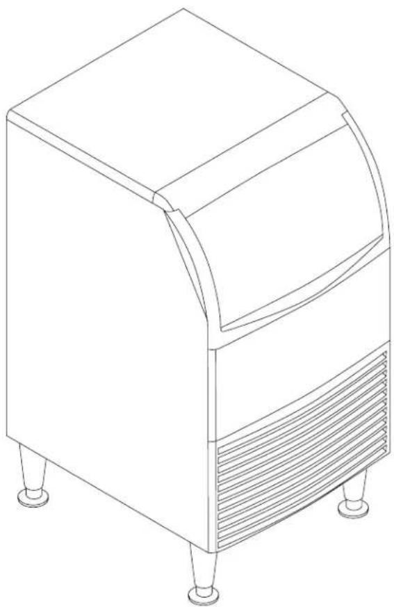
Installation and User's Manual for Cube Ice Machine with storage models CUR0415, CUR0715 and CUR0920
Introduction
The design of this product is the result of years of experience in developing commercial ice cube machines. It has been designed for simple operation in a wide range of locations. Please follow the instructions for installation and maintenance to get the most use from this ice machine.
Table of Contents
Important Details 2
Pre-Installation....3
Cabinet Layout, CUR0415 and CUR0715....4
Cabinet Layout, CUR0920....5
Component Location 6
Connect the water supply....7
Connect the power 8
Control Panel and Adjustments 9
Initial Start Up....10
Use and Operational Notes ...... 11
Maintenance....12
Before calling for service 14
208-230/60/1 wiring diagram....15
Observe the Caution and Warning notices. They are indicators of important safety information. Keep this manual for future reference.
Important Details
The machine is designed for use indoors in a controlled environment. It must be kept dry, not overheated or subjected to excessive cold. The water and power supply must be maintained or the machine will stop making ice.
There are limits to how hot or cold the room it's in can be.
• Minimum air temperature: 50 or 10°C
• Maximum air temperature: 10°F or 38°C.
There are also limits to how hot or cold the water supply can be:
• Minimum water temperature: 40 or 4.5°C
• Maximum water temperature: 10°F or 38°C.
There are limits to the voltage supply to the unit, voltages vary by model:
Voltage
| 220 (-32) | |
| Minimum 198 | |
| Maximum 242 | |
Water supply must be potable by the localities definition.
There are limits to the water pressure supplied to the unit:
• Maximum pressure. static: 80 psi or 5.5 bar or 551.6 kilopascals.
• Minimum pressure, dynamic: 15 psi or 1 bar or 103.4 kilopascals.
A drain will be needed for melted ice and rinse water.
Warranty:
The warranty statement for this product is provided separately from this manual. Refer to it for applicable coverage. In general warranty covers defects in material or workmanship. It does not cover maintenance, corrections to installations, or situations when the machine is operated in circumstances that exceed the limitations printed above.
The manufacturer has designed and produced this machine with the finest in materials. The manufacturer assumes no liability for units that have been altered in any way. Alterations or part substitutions will void the warranty. Specifications and designs are subject to change without notice.
Pre-Installation
This appliance is intended to be used in commercial applications including:
- Restaurant kitchens
- Bars
- Hotels
Spacing:
No additional spacing is required at the top or sides. However, suggested minimum side clearance for installation is 1/8 inch or 3 mm and suggested minimum top clearance is 1/4 inch or 7 mm.
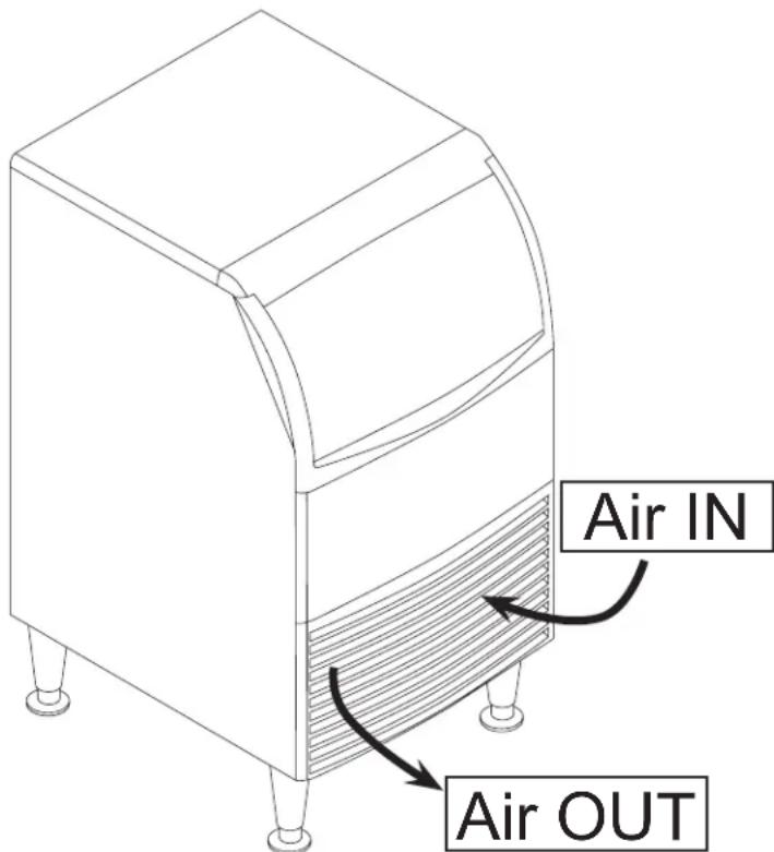
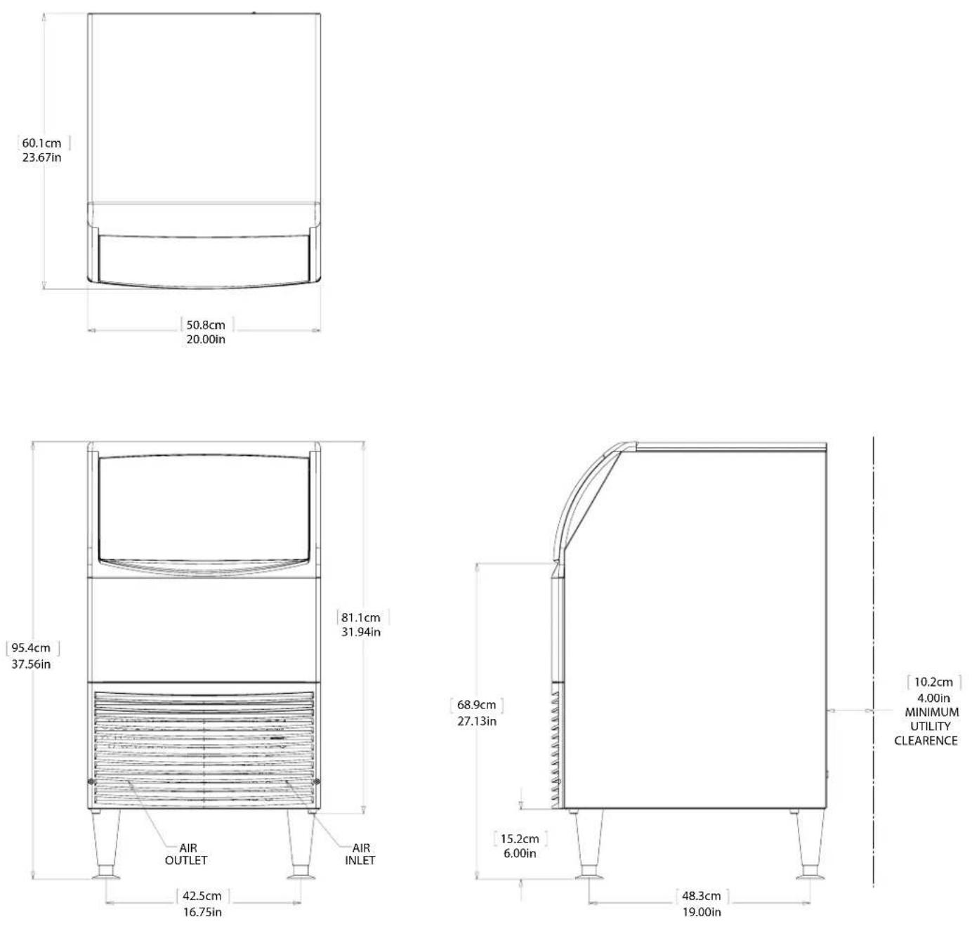
Allow 4 inches (100 mm) minimum space at the back for the utility connections. Do not block louvers at the front of the cabinet.
Dimensions and Electrical:
| Model Electrical | (volts/Hz/Phase) | Width(in / cm) | Depth(in/cm) | Height(in/cm) | Total Load Amps |
| CUR0415MA-32A 2 | 20/60/1 15 / 38 23.7 / | 60.3 31.9 / 81.1 | 4 | ||
| CUR0715MA-32A 2 | 20/60/1 15 / 38 23.7 / | 60.3 31.9 / 81.1 | 4 | ||
| CUR0920MA-32A 2 | 20/60/1 20 / 51 23.7 / | 60.3 31.9 / 81.1 | 4 |
Location:
The unit can be built into a cabinet as the air flow is in and out the front. The front of the machine must not be blocked. Certain maintenance or repair procedures will require removal of the top, back and side panels, so plan ahead for service and maintenance needs.
Unpacking and setup
Remove all shipping and packing materials that may be in the ice storage bin.
The unit can be installed with or without legs. The cabinet is equipped with small bumpers on the base to allow placement without legs. An optional floor mounting kit is also available to fill the gap between the machine and floor if not using legs. If using legs, carefully tip the machine and install the legs by screwing them into the leg sockets in the bottom of the machine. For reference, the thread size is 5/8 – 11. If the machine has been tipped onto its side or back allow 1 hour before starting the unit for the oil in the refrigeration system to return to the compressor.
Place the machine in its intended location and level it front to back and left to right. If using legs, adjust their feet in and out to level the cabinet.
If legs are not used the bottom edges of the cabinet must be sealed to the floor.
No additional means of support are needed.
If built into a cabinet, the adjacent cabinet walls will provide the means for containment. There are no means for attachment to the cabinet.
Cabinet Layout, CUR0415 and CUR0715

Cabinet Layout, CUR0920
Component Location
Connect the water supply
Plumbing information:
There is a single 3/4 gas BNF inlet water connection and a connecting hose is supplied.
Note: New connecting hose is supplied do not reuse old hose set.
- A hand actuated valve within site of the machine is required to isolate the unit when being serviced.
- The machine has a built-in back flow preventer (an air gap between the end of the water inlet hose and the top of the water), no additional back flow preventer is needed.
Units that are built into a cabinet:
Include a loop or coil of tubing between the water supply and the connection on the ice machine. When the machine is pushed back into the cabinet the tubing will coil and not kink.
Connection Information:
WARNING: connect to potable water supply only.
Important: Open the hand water valve to flush water through the tubing before connecting to the ice machine.
230 volt models: Connect cold potable water to the 3/4 gas fitting on the unit using the supplied hose.
Note: Do not use a piercing-type saddle valve to connect to the building's water supply. Valves of that type restrict water flow and clog easily.
Connect the drain
The drain connection is at the back panel. The fitting size is 3/4 FPT. Connect rigid tubing to this fitting and vent it at the machine, use an 8 inch or 200 mm vertical tube for the vent.
Drain tubing must slope down from the ice machine to the building drain and the slope must be at least
1/4 inch per foot or 20 mm per meter. Insulating the drain tubing will reduce condensation and is recommended for environments that have high humidity.
Due to the potential for leaks, condensate pumps are not recommended.

New Hose Set
Drain - Must be Vented
Connect the power
This is a cord-connected unit, and must be connected to its own dedicated power supply. Check the dataplate on the back of the machine for the proper voltage and per the dataplate use fuses or HACR circuit breakers.
Power Cords:
230 volt, 60 Hz models are equipped with a 14136 power cord and plug.
Note: In case the power cord is damaged, it must be replaced by a like cord. Replacement cords are available from the manufacturer's local representative. Replacement should only be done by a qualified technician to prevent possible risks.
The power cord plug will be the disconnect means for the machine and must be accessible when the unit is in its permanent location.
Follow All Local Codes - This Unit Must Be Grounded. Do not use extension cords and do not disable or by-pass ground prong on electrical plug.
Plug the power cord into the power supply.
Installation check list
- Has the machine been installed indoors in an environment suitable for it?
• Have all of the shipping items and packaging been removed?
• Is the ice chute in the correct position?
• Is the clear plastic curtain hanging down and free to move?
• Has the water supply been connected and confirmed to not leak? - Has a properly sized and sloped drain tube been attached?
- Has the correct voltage power supply been connected?

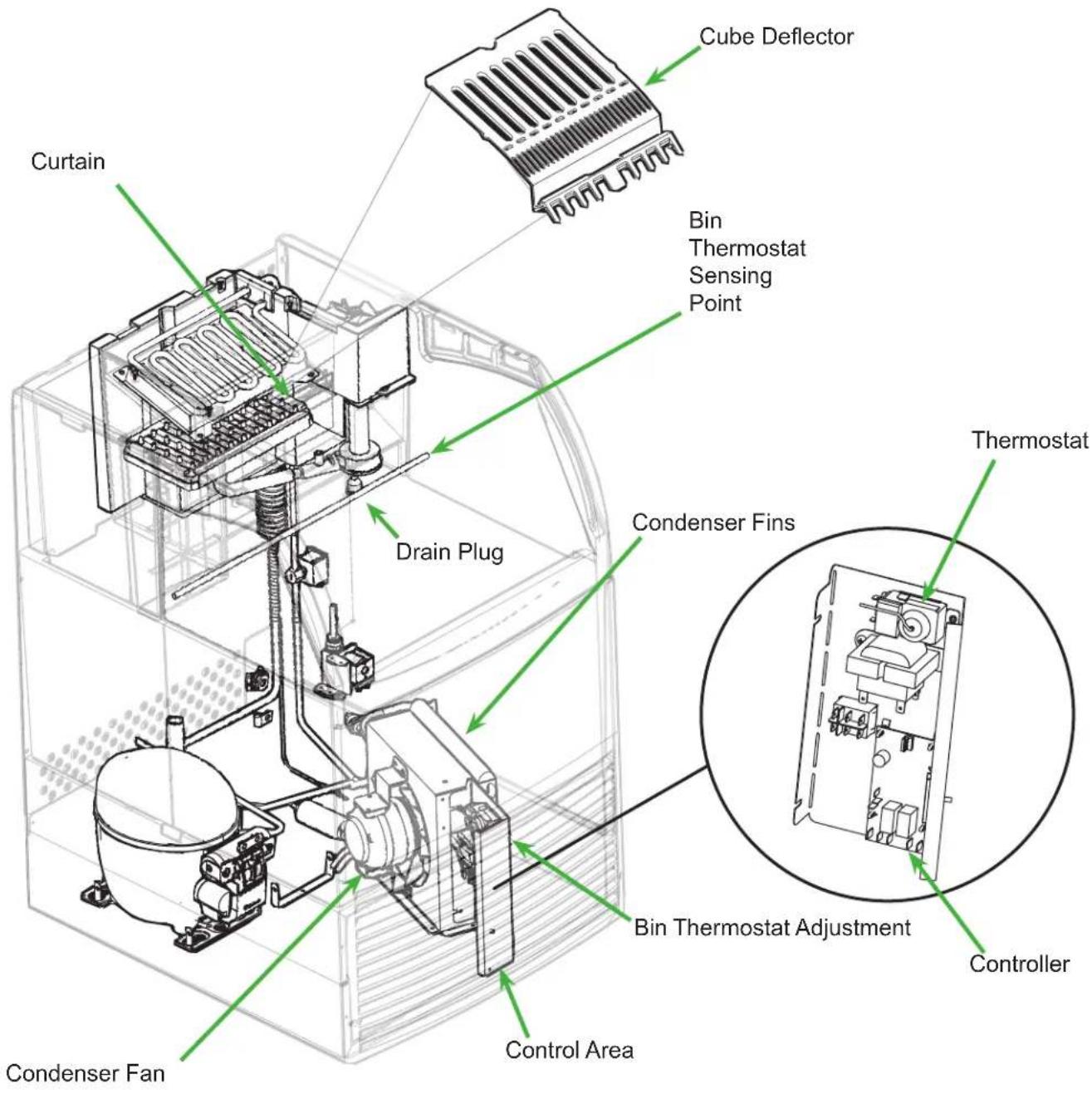
Front view of freezing compartment, right arrow points to clear plastic curtain. It must hang freely. Left arrow points to Cube Deflector, it must be positioned as shown.
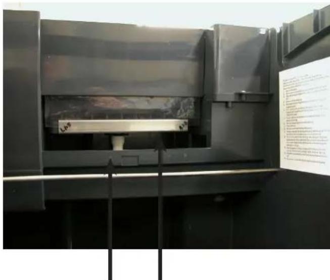
Front view of freezing compartment, shown without Ice Chute or Curtain. Right arrow points to Spray Platform, located under Ice Chute. Spray Platform inlet connects to pump hose and is snapped into clip at back of reservoir. Left arrow points to clip.
Control Panel and Adjustments
Ice Bridge Thickness Adjustment Area

Master Switch. Move to ON (left side depressed) to make ice, OFF (centered) to shut off and WASH (right side depressed) for use in cleaning.
Harvest Time Adjustment Area
Indicator Light Area.
Freeze mode light is ON when unit is in a Freeze cycle.
Timer On light is ON when trigger point temperature is reached in Freeze or Harvest.
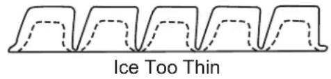
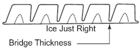
Ice Thickness Diagram Ice Bridge Thickness Adjustment

Adjustment Indicator Lights
Each push and release of the + or - button will change the lights that glow or blink indicating a change in ice size or harvest time. Example: pushing + one time changes a blinking light to steady on type. If the lights are on steady a single push of + will add one more light to the right and it will blink. There are 10 settings. All 5 lights on steady is the maximum setting and one blinking light is the minimum.
Refer to the Ice Thickness Diagram for proper ice size.
Adjust by pushing the + sign or – sign on the ice bridge adjustment section of the control panel. Changing bridge thickness should be a one-time adjustment as the machine will automatically maintain that ice thickness.
Harvest Cycle Time Adjustment
After ice has formed in the inverted mold, it must be released so it can be deposited in the storage bin section. The harvest cycle is when that occurs, and must be long enough for the ice to release. While the harvest cycle length is self adjusting it can also be manually adjusted if needed.
Proper harvest time is when the ice falls into the bin and there is about 10 seconds extra harvest time (pump and fan are off) before the freeze cycle restarts.
If the harvest time is too short to release the ice, the time may be increased by pushing the + sign on the harvest time adjustment section of the control panel. Operate the machine for another cycle to confirm that the adjustment was correct. Note that too much harvest time will slightly decrease making ice capacity.
Initial Start Up
- Remove the front panel by removing the two screws holding it to the cabinet and pulling the panel down and off the machine.
- Turn on the water supply, correct any leaks.
Note: Water supply MUST be turned on first to allow water to enter the machine properly.
- Locate the On/Off/Wash master switch.
- Move the switch to the On position.
- Ice bridge thickness and harvest time indicator lights will switch on. They will not change unless the cube size or harvest times are manually adjusted. The timer light will also be on.
- The unit begins to fill the reservoir with water. Two streams of water can be seen behind the curtain. The compressor and hot gas valve will be energized, but the fan motor and pump will be off. After a time the water will have filled the reservoir but will continue to fill and excess water will drain from the machine. This is normal and helps the machine from forming excessive mineral scale.
- After 2 minutes the water and hot gas valves will close and the pump and fan motors will start. A blue light in the control panel will glow indicating the beginning of the freeze cycle.
- Warm air will begin to blow out the left front of the machine and water will spray up at the inverted ice making mold. It is normal for a small amount of water to drip from the ice making area.
When the water temperature reaches a pre-set point the water pump will stop for about 30 seconds then resume.
Freezing then continues for many minutes until the temperature of the refrigeration system drops to a set point, indicated by a yellow light glowing on the control panel. In colder rooms the fan motor may turn on and off. After the yellow light switches on the freeze cycle continues for seven more minutes. At that time the unit changes to the ice release or harvest cycle. During the ice harvest the hot gas valve and inlet water valve are open, while the pump and fan motors will stop. The blue and yellow lights will go out. Water will refill the reservoir.
- Within a minute or so the ice formed in the mold will fall down and slide into the ice storage bin. The ice will release as a group so all of the ice formed will fall at once and the next freeze cycle will begin in a few seconds. The timer light may switch on at the end of the harvest cycle.
- Check the thickness of the ice connecting the cubes to each other, that connection is known as a bridge and it should be about 1/8 inch or 3 to 4 mm thick. It is preset from the factory and should be satisfactory.
Adjustments:
If the ice bridge is too big or too small, the thickness may be adjusted.
Note: The bridge thickness adjustment is used to obtain the CORRECT size, not to adjust to individual preferences. Do NOT make the ice bridge too thick or too thin, as either will reduce ice making capacity. Do NOT attempt to adjust the machine to release individual cubes. There is only ONE correct size.
- Ice making will continue until the ice level reaches the metal tube in the storage bin, when ice contacts that tube the machine will stop making ice. This can occur in any part of any cycle.
- Removing ice from the ice storage bin will restart the ice making process.
- Check for and correct any water leaks from the unit or drain system.
- Return the front panel to its normal position and secure it to the cabinet with the original screws.
Typical Cycle Times (minutes)
Note: First cycle after any restart will be longer than listed here.
| 70/50°F. (21/10°C.) 90/ | 70 °F. (32/21°C.) | |
| CUR0415 2 | 8-30 34-37 | |
| CUR0715 1 | 6-18 23-26 | |
| CUR0920 1 | 4-16 17-19 |
The time to fill a warm storage bin from empty varies by cabinet temperature and cycle time, but will take about 10-12 hours.
Use and Operational Notes
To use, simply lift the door by its bottom edge and slide it up and into the top of the machine. Use the scoop to remove ice and close the door.
The machine will make the most ice if it has plenty of room to breathe. This is an air cooled product and it must be able to take in room air and discharge air heated by the ice making process. Blockage of vents or exposure to excessive heat will reduce the ice making and storage capacity. The storage bin is insulated but not refrigerated, so ice will melt during use. That is normal and assures that fresh ice is available in the bin.
The fan will make some noise during operation, however rattles and other vibrations are not normal and should be attended to. When the air temperature surrounding the machine is cold, the fan might cycle on and off during the freeze mode.
If the machine is in a space colder than the minimums listed it will not switch on to make ice.
Minor adjustments may be made to compensate for local conditions by rotating the adjustment screw visible above the control area. If in a cold room, CW rotation changes the control to COLDER to fill the bin higher.
If installed at an altitude greater than 2000 ft or 610 meters above sea level, the bin thermostat may need internal adjustment. The adjustment screw is behind the front of the control, accessed through a hole for it
Bin Thermostat Altitude Adjustment Table:
| Altitude (ft) Altitude (meters) Degree of adjustment | |
| 0 0 11 CCW | |
| 500 150 none | |
| 1000 300 11 CW | |
| 2000 600 31 CW | |
| 3000 900 52 CW | |
| 4000 1200 72 CW | |
| 5000 1500 92 CW | |
| 6000 1800 111 CW | |
| 7000 2100 128 CW | |
| ▲CAUTION | No StepDo not stand on the machine.Severe damage can occur. |
This appliance is not intended for use by persons (including children) with reduced physical, sensory or mental capabilities, or lack of experience and knowledge, unless they have been given supervision or instruction concerning use of the appliance by a person responsible for their safety.
Children should be supervised to ensure that they do not play with the appliance.
Maintenance
Regularly vacuum the right side of the air cooled condenser with a brush to remove all loose dust and dirt. Be careful not to damage the fins.
Cubed ice machines of this type make ice that is more pure than the water supplied to it. Since the ice has fewer impurities, the water that remains in the reservoir has more. The water system dilutes that concentration but eventually it does build up and need to be removed. Over the years it has been determined that the scale removal frequency is about 2 times per year.
To remove scale from the water system.
Materials needed:
Food grade, nickel safe scale remover for ice machines, also known as ice machine cleaner.
- Sanitizer
- Hand tools.
- Clean bucket
- Clean cloths
• Rubber or plastic gloves
-
Remove front panel.
-
Move master switch to Off, wait a minute and then move it to On.
-
When the freeze cycle begins (blue light on), switch the machine to Off.
-
Remove and discard the ice.
-
Drain reservoir by pulling drain plug and return drain plug to its original position.
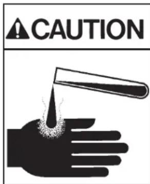
Ice machine scale remover contains acids. Acids can cause burns.
If concentrated cleaner comes in contact with skin, flush with water. If swallowed, do NOT induce vomiting. Give large amounts of water or milk. Call Physician immediately. Keep out of the reach of children.
- Mix a solution of 5 oz or 150 cc of Scotsman Clear 1 Scale Remover and 2.5 quarts or 2.4 liters of clean, warm (95°F/35°C to 115°F./46°C) water.
- Pour the solution into the reservoir by carefully adding it at the reservoir's front lip.
- Move the master switch to the Wash position.
- Wait 10 minutes.
- Move the master switch to the Off position.
- Drain the reservoir by removing drain plug and draining the solution into the bin. Return the drain plug to its normal position.
- Remove spray platform by removing cube chute and lifting spray platform up and off its connection. Open platform and confirm all jets are open. Rinse out any debris, reclose and return it and the cube chute to the unit.
- Pour 2.5 quarts or 2.4 liters of warm (95°F/35°C to 115°F./46°C) water into the reservoir by adding it at the reservoirs' front lip.
- Switch the master switch to Wash for 1 minute, then switch it to Off.
- Repeat step 11. Go to the next process to sanitize the machine.
Sanitize Water System – after completing prior scale removal and stopping at the end of its steps. - Mix a 1 gallon or 4 liter solution of locally approved sanitizer and clean, warm (95°F/35°C to 115°F./46°C) water. Use an EPA approved food equipment sanitizer at the solution mix recommended by the sanitizer manufacturer.
- Pour about half of the sanitizer mix into the reservoir.
- Remove the cube chute and spray platforms and wash them with the sanitizer, then return them to the ice machine.
- Move the master switch to the Wash position.
- Circulate the sanitizer for 2 minutes.
-
Move the master switch to Off.
-
Drain the reservoir into the storage bin by removing the drain plug. Return the drain plug to its normal position.
- Wash all interior surfaces of the ice machine storage bin, reservoir surface and inside of the door with the remaining sanitizer solution.
- Pour any excess sanitizer down the ice machine bin drain.
- Pour 2.5 quarts or 2.4 liters of warm (95°F/35°C to 115°F./46°C) water into the reservoir by adding it at the reservoirs' front lip.
- Move the master switch to the Wash position for 1 minute, then switch it to Off.
- Drain the reservoir by removing the drain plug and draining the solution into the bin. Return the drain plug to its normal position.
- Move switch to the On position. The machine will resume normal ice making.
- Return the front panel to its original position and secure it with the original screws.
Before calling for service
No ice – check water supply
No ice – check power supply. Remove front panel, if there are no lights on the control panel either the bin thermostat is open OR there is no power to the controller.
No ice – check temperature of cabinet. If too cold the machine will not operate.
Slow production – check condenser for dirt, clean condenser.
Slow production – check temperature of cabinet, if the room is hot or air flow restricted, production will be slow.
Ice is poorly formed. Check spray. If some spray jets are restricted, ice will be poorly formed. Clean water system to correct.
Note: In areas where the water supply has a high mineral content, the spray jets may need frequent clearing. Increasing the harvest time will flush more water and help to reduce the frequency of cleaning.
To increase harvest time:
- Confirm unit is in ice making mode. If the bin is full and the unit is off the controller cannot be adjusted.
- Remove the front louvered panel.
- Increase the time by pushing the + sign on the harvest time adjustment section of the control panel. Each push increases the time.
- Return the front louvered panel to its normal position.

COLDMIX INDUSTRIA, COMERCIO E REP. LTDA.
Rio de Janeiro, RJ Brazil,
CEP: 20.931-670
www.coldmix.com.br
+55-21-3147-1000
- INTRODUÇÃO
- INSTALLATION AND USER'S MANUAL FOR CUBE ICE MACHINE WITH STORAGE MODELS CUR0415, CUR0715 AND CUR0920
- INTRODUCTION
- TABLE OF CONTENTS
- IMPORTANT DETAILS
- WARRANTY
- PRE-INSTALLATION
- SPACING
- LOCATION
- UNPACKING AND SETUP
- CABINET LAYOUT, CUR0415 AND CUR0715
- CABINET LAYOUT, CUR0920
- COMPONENT LOCATION
- CONNECT THE WATER SUPPLY
- PLUMBING INFORMATION
- NOTE: NEW CONNECTING HOSE IS SUPPLIED DO NOT REUSE OLD HOSE SET
- CONNECT THE DRAIN
- CONNECT THE POWER
- INSTALLATION CHECK LIST
- CONTROL PANEL AND ADJUSTMENTS
- ICE THICKNESS DIAGRAM ICE BRIDGE THICKNESS ADJUSTMENT
- ADJUSTMENT INDICATOR LIGHTS
- HARVEST CYCLE TIME ADJUSTMENT
- INITIAL START UP
- ADJUSTMENTS
- TYPICAL CYCLE TIMES (MINUTES)
- USE AND OPERATIONAL NOTES
- MAINTENANCE
- BEFORE CALLING FOR SERVICE
- COLDMIX INDUSTRIA, COMERCIO E REP. LTDA
Brand : Scotsman
Model : CUR0715
Category : Ice Maker