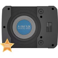
XLf 185 A - Subwoofer BLAUPUNKT - Free user manual and instructions
Find the device manual for free XLf 185 A BLAUPUNKT in PDF.


| Product Type | Active Subwoofer |
| Speaker Size | 8.0 inches |
| Cone Material | Aluminum |
| Magnet Type | Ferrite |
| Enclosure Material | Aluminum |
| Enclosure Dimensions (L x W x H) | 345 x 260 x 75 mm |
| Net Weight | 5 kg |
| Amplifier Technology | Class AB |
| RMS Power Output | 180 W |
| Max Power Output | 450 W |
| Frequency Response | 30 Hz – 150 Hz |
| Signal-to-Noise Ratio | 91 dB |
| Output Impedance | 2 ohms |
| Input Sensitivity (RCA) | 0.2 V – 10 V |
| Input Sensitivity (Speaker Level) | 0.6 V – 12 V |
| Low Pass Filter (LPF) | 50 Hz – 150 Hz |
| Variable Bass Boost | 0 – 18 dB |
| Phase Switch | 0° / 180° |
| Auto Power On/Off | High Level Only |
| Passive Radiator | 192 x 60 mm |
| Power Supply Voltage | 14.4 V (10 V – 16 V) |
| Fuse Rating | 25 A |
| Accessories Included | Remote control, DC cord, mounting brackets, screws, speaker extensions |
| Installation Positions | Down-firing, side-firing, up-firing |
| Safety Features | Protection LED, overload protection |
Frequently Asked Questions - XLf 185 A BLAUPUNKT
User questions about XLf 185 A BLAUPUNKT
0 question about this device. Answer the ones you know or ask your own.
Ask a new question about this device
Download the instructions for your Subwoofer in PDF format for free! Find your manual XLf 185 A - BLAUPUNKT and take your electronic device back in hand. On this page are published all the documents necessary for the use of your device. XLf 185 A by BLAUPUNKT.
USER MANUAL XLf 185 A BLAUPUNKT
ACTIVE SUBWOOFER XLf 185 A

Enjoy it.
Proper system planning is vital in order to maximize the device's performance and road safety. Plan your installation carefully to avoid compromising performance reliability of the system. Consult an authorized Blaupunkt dealer for installation or preparation. Read the manual carefully before operating the device for the first time.
Safety Notes
Ensure to follow below safety notes during installation and wiring connection: -
- Disconnect the negative terminal of the battery. Refer to the safety notes of the vehicle manufacturer.
- Ensure positions of the holes are nowhere near the vehicle component to avoid any damage during drilling.
- Ensure cross section of the cable is no less than 2.5mm2 if the positive and negative cables are too long.
- Incorrect installation may result in malfunction of the device or the car sound system.
Installation and Connection Instructions
- Select a dry and well-ventilated location to install the device.
- The device must not be installed in overly exposed location such on the rear shelf, rear seat etc.
- The installation location must be suitable for screw holes and have stable ground support.
Intergrated Fuse
- The integrated fuse in the device protects the output voltage and the entire electrical system in case of malfunction. Do not replace damaged fuse with higher current.
Switching On/Off
- This device will automatically turn on if audio signal is detected. The device will also automatically turn off if audio signal is received.
Disclaimer
In no event shall Blaupunkt be liable for any direct, indirect, punitive, incidental, special consequential damages to property or life and whatsoever arising out of or connected with the use or misuse of our products.
USA & CANADA: This product is not intended for sale in the United States and Canada. If purchased in the U.S. or Canada, this product is purchased on as-is basis. No warranty, whether expressed or implied is provided in the U.S. or Canada.
Remote Control

- Power Indicator
- Gain Adjustment
Turn the gain knob to adjust the volume to the desired level.
Disposal Notes
Do not dispose of your old unit in the household trash! Use the return and collection systems available to dispose of the old device.
This manual may be updated from time to time without any notice. Visit www.blaupunkt.com for more info.

- Power / Speaker Input
- RCA Input (CH1/CH2)
- Remote Control Input
- Phase (0°\~ 180°)
- Auto Power On (On/Off)
- Input Gain (200mV \~ 6V)
- Bass Boost (0 \~ +18dB)
- Low Pass (50Hz \~ 150Hz)
- Power LED Light
- Protection LED Light
INSTALLATION

Down Firing Position

natural_image
Line drawing of a rectangular electronic device with a mesh grille and mounting holes, no text or symbols present.Side Firing Position

natural_image
Technical line drawing of a mechanical component with mounting holes and a central cavity (no text or symbols)Up Firing Position

natural_image
Line drawing of a rectangular electronic device with a black cover and mounting holes, no text or symbols present.

Subwoofer
- Speaker Size: 8.0"
• Cone Composition : Aluminium - Magnet Type : Ferrite
• Enclosure Housing Material : Aluminum - Enclosure Dimension (L x W x H) : 345 x 260 x 75mm
• Enclosure Net Weight : 5kg
Amplifier
• Amplifier Technology : Class AB
• Normal Output Power (RMS) : 180W
• Max Output Power : 450W
- Audio in Sensitivity : RCA input 0.2V-10V, Speaker input 0.6V-12V
• Signal/Noise Ratio : 91dB
• Output Impedance : 2 ohms
• Frequency Response : 30Hz-150Hz
• Low Pass Filter (LPF) : 50Hz-150Hz
• Voltage : 14.4V (10V-16V)
• Phase Switch : 0 deg /180 deg
• Automatic On/Off : High Level Only
- Gain: 200mV - 6V
• Passive Radiator : 192 x 60mm
• Variable Bass Boost : 0 – 18dB
Accessories

2x Screws (M6x8)

2x Screws (M4x20)

2x Mounting Bracket (71 x 39.5 x 7mm)

natural_image
Line drawing of a handheld medical device with a probe and screwdriver (no text or symbols)1x 4.5m Remote Controller

1x 4.5m DC Cord

High level Input Speaker Extension

Low level Input Speaker Extension

natural_image
Pure electrical connector diagram without any text, numbers, or symbolsInput Plug Extension
Use the supplied cable and wire harness to connect the outputs correctly by referring to Diagram 1 & Diagram 2.
Diagram 1 (High Level Input -Speaker Input)

flowchart
graph TD
    A["AUTO POWER ON = ON"] --> B["REMOTE CONTROL"]
    B --> C["YELLOW WIRE"]
    C --> D["FUSE 25A"]
    D --> E["BATTERY 12V"]
    E --> F["CHASSIS GROUND"]
    B --> G["CONNECT BLACK WIRE TO THE CHASSIS OF THE VEHICLE"]
    G --> H["BLUE/WHITE WIRE = NOT IN USE IN THIS TYPE OF INSTALLATION"]
    H --> I["GREY/BLACK (-) & GREY WIRE (+)"]
    I --> J["WHITE/BLACK (-) & WHITE WIRE (+)"]
    J --> K["SPEAKER RIGHT CHANNEL OUTPUT WIRE"]
    K --> L["AUDIO DEVICE"]
    L --> M["SPEAKER LEFT CHANNEL OUTPUT WIRE"]
    M --> N["Chassis Ground"]
Diagram 2 (Low Level Input -RCA Input)

flowchart
graph TD
    A["AUTO POWER ON=OFF"] --> B["REMOTE CONTROL"]
    B --> C["RCA SIGNAL WIRE (NOT INCLUDED)"]
    C --> D["AUDIO DEVICE"]
    D --> E["25A FUSE"]
    E --> F["BATTERY"]
    F --> G["CHASSIS GROUND"]
    G --> H["AUDIO DEVICE CONTROL WIRE"]
    H --> I["AUDIO DEVICE"]
    I --> J["CONNECT BLACK WIRE TO THE CHASSIS OF THE VEHICLE"]
    J --> K["BLUE/WHITE WIRE"]
    K --> L["NOT IN USE IN THIS TYPE OF INSTALLATION"]
    L --> M["Yellow WIRE"]
    M --> N["FUSE"]
    N --> O["12V"]
If any of the following problem occur, please resort to Troubleshooting for the possible solutions. Consult Blaupunkt authorized dealer if problem persist.
| Problem | Solution |
| Amplifier power up failure | Examine if the ground connection is intact. |
| Examine if remote input has at least 5V DC. | |
| Examine if battery power is connected correctly to the + terminal. | |
| Ensure supplied voltage is minimum 12V. | |
| Examine if fuse is broken and replace if necessary. | |
| Restart the device if protection LED light is on. | |
| Protection LED lights on when turn on | Examine if speaker wire had short-circuit. |
| Turn volume down from head unit to prevent overdriving the device. | |
| Device might need service or repair, if protection LED light is still on after resetting the device. | |
| No sound output | Examine fuses and replace if necessary. |
| Examine if ground connection is intact. | |
| Examine if remote input has at least 5V DC. | |
| Examine if RCA audio cables are connected to the right inputs. | |
| Examine if speaker wiring is intact. | |
| Low sound output | Reset Level Control |
| Examine the Crossover Control setting. | |
| Buzzing noise | Observe if the device is still producing noise after turning on and off the amplifier. If yes, examine if the cables are correctly connected and if the cables and radio are in good condition. Repair or replace if the cables or the radio are not in good condition. |
| Squealing noise interference | Ensure RCA connections are properly connected. |
| Distorted sound output | Ensure input level of the device matches the signal level of the head unit. |
| Always set the input level to the lowest. | |
| Examine if crossover frequency is set correctly. | |
| Examine if speaker wire had short-circuit. | |
| Amplifier temperature increased | Examine if the minimum speaker impedance for the amp models is correct. |
| Ensure good air ventilation around the device. Add external cooling fan if necessary. | |
| Engine noise (static sound) interference | Usually caused by poor RCA cable quality, which release noise. Use only the best quality cables, and route them away from power cables. |
| Engine noise (alternator whine) interference | Examine if RCA cable are nowhere near or attached to the vehicle chassis. |
| Examine if head unit is properly connected to the wires. |


Brand : BLAUPUNKT
Model : XLf 185 A
Category : Subwoofer