
FFED3025LB - Frying Pan FRIGIDAIRE - Free user manual and instructions
Find the device manual for free FFED3025LB FRIGIDAIRE in PDF.


| Product Type | Electric Range |
| Brand | Frigidaire |
| Model | FFED3025LB |
| Width | 30 inches |
| Depth | 28.5 inches |
| Height | 47.25 inches |
| Weight | 150 lbs |
| Power Supply | 240V, 40A |
| Burner Configuration | 4 coil burners |
| Oven Capacity | 5.3 cu. ft. |
| Oven Functions | Bake, Broil, Self-Cleaning |
| Control Type | Knobs and digital display |
| Timer | Yes |
| Oven Light | Yes |
| Storage Drawer | Yes |
| Cleaning Method | Self-cleaning cycle |
| Safety Features | Auto shut-off, child lock |
| Color | Black |
| Warranty | 1 year limited |
| Certification | UL Listed |
Frequently Asked Questions - FFED3025LB FRIGIDAIRE
User questions about FFED3025LB FRIGIDAIRE
0 question about this device. Answer the ones you know or ask your own.
Ask a new question about this device
Download the instructions for your Frying Pan in PDF format for free! Find your manual FFED3025LB - FRIGIDAIRE and take your electronic device back in hand. On this page are published all the documents necessary for the use of your device. FFED3025LB by FRIGIDAIRE.
USER MANUAL FFED3025LB FRIGIDAIRE
INSTALLATION INSTRUCTIONS 30" ELECTRIC DROP-IN RANGE
INSTALLATION AND SERVICE MUST BE PERFORMED BY A QUALIFIED INSTALLER. IMPORTANT: SAVE FOR LOCAL ELECTRICAL INSPECTOR'S USE. READ AND SAVE THESE INSTRUCTIONS FOR FUTURE REFERENCE.
United States

WARNING FOR YOUR SAFETY: Do not store or use gasoline or other flammable vapors and liquids in the vicinity of this or any other appliance.
Table of Contents
Important Safety Instructions 2
Cutout Dimensions 3-4
Electrical Requirements 5
Electrical Connection 5-6
Serial Plate Location 6
Range Installation 7
Anti-tip Bracket Installation 8-9
Check Operation 10
Model and Serial Number Location 10
Before you call for Service 10
Important Notes to the Installer
- Read all instructions contained in these installation instructions before installing range.
- Remove all packing material from the oven and the drawer compartments before connecting the electrical supply to the range.
- Observe all governing codes and ordinances.
- Be sure to leave these instructions with the consumer.
Important Note to the Consumer
Keep these instructions with your owner's guide for future reference.
30" ELECTRIC DROP-IN RANGE INSTALLATION INSTRUCTIONS
IMPORTANT SAFETY INSTRUCTIONS
This manual contains important safety symbols and instructions. Please pay attention to these symbols and follow all instructions given.
WARNING This symbol will help alert you to situations that may cause serious bodily harm, death or property damage.
CAUTION This symbol will help alert you to situations that may cause bodily injury or property damage.
- Be sure your range is installed and grounded properly by a qualified installer or service technician.
- This range must be electrically grounded in accordance with local codes or, in their absence, with the National Electrical Code ANSI/NFPA No. 70—latest edition.
- The installation of appliances designed for manufactured (mobile) home installation must conform with Manufactured Home Construction and Safety Standard, title 24CFR, part 3280 [Formerly the Federal Standard for Mobile Home Construction and Safety, title 24, HUD (part 280)] or when such standard is not applicable, the Standard for Manufactured Home Installation 1982 (Manufactured Home Sites, Communities and Setups), ANSI Z225.1/NFPA 501A-latest edition, or with local codes.
- Make sure the wall coverings around the range can withstand the heat generated by the range.
- Before installing the range in an area covered with linoleum or any other synthetic floor covering, make sure the floor covering can withstand heat at least 90°F above room temperature without shrinking, warping or discoloring. Do not install the range over carpeting unless you place an insulating pad or sheet of 1/4" thick plywood between the range and carpeting.
WARNING Never leave children alone or unattended in the area where an appliance is in use. As children grow, teach them the proper, safe use of all appliances. Never leave the oven door open when the range is unattended.
WARNING Stepping, leaning or sitting on the door of this range can result in serious injuries and can also cause damage to the range.
- Do not store items of interest to children in the cabinets above the range. Children could be seriously burned climbing on the range to reach items.
- To eliminate the risk of burns or fire by reaching over heated surface units, cabinet storage space above the surface unit should be avoided.
If cabinet storage is to be provided the risk can be reduce by installing a range hood that project
horizontally a minimum of 5 inches beyond the bottom of the cabinet.
- Do not use the oven as a storage space. This creates a potentially hazardous situation.
- Never use your range for warming or heating the room. Prolonged use of the range without adequate ventilation can be dangerous.
- Do not store or use gasoline or other flammable vapors and liquids near this or any other appliance. Explosions or fires could result.
- Reset all controls to the "off" position after using a programmable timing operation.
FOR MODELS WITH SELF-CLEAN FEATURE:
- Remove broiler pan, food and other utensils before self-cleaning the oven. Wipe up excess spillage. Follow the pre cleaning instructions in the Use and Care Guide.
WARNING
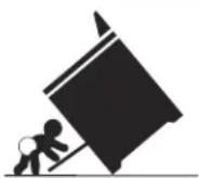
Tip Over Hazard
A child or adult can tip the • range and be killed.
Verify the rear bracket is • engaged with countertop or the anti-tip device has been installed to the walls of the
cabinet as per installation instructions.
Ensure the anti-tip bracket is re-engaged with • the countertop or to the cabinet side walls as per the installation instructions when the range is moved.
Do not operate the range without the anti-tip • device in place and engaged.
Failure to follow these instructions can result in • death or serious burns to children and adults.
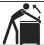
To check if the anti-tip bracket is installed properly, use both arms and grasp the rear edge of range back. Carefully attempt to tilt range forward. When properly installed, the
range should not tilt forward.
Refer to the anti-tip bracket installation instructions supplied with your range for proper installation.
30" ELECTRIC DROP-IN RANGE INSTALLATION INSTRUCTIONS
Cutout Dimensions

Grounded Junction Box in adjoining Cabinet

NOTE: Two sets of holes are provided under anti-tip bracket. Bracket is attached in the upper hole position at the factory. Refer also to page 6, item 9 for additional details.

| A. Cutout Width (Countertop and cabinet) | B. Cutout Depth (According to front of cabinet) | C. Height of Cutout |
| 30 ± 1/16" (76.2 ± 0.15 cm) | 21 3/4" (55.2 cm) min22 1/8" (56.2 cm) max | 29" (73.7 cm) |
30" ELECTRIC DROP-IN RANGE INSTALLATION INSTRUCTIONS
NOTES:
- Do not pinch the power supply cord between the range and the wall.
- Do not seal the range to the side cabinets.
- 24" (61 cm) minimum clearance between the cooktop and the bottom of the cabinet when the bottom of wood or metal cabinet is protected by not less than 1/4" (0.64 cm) flame retardant millboard covered with not less than No. 28 MSG sheet metal, 0.015" (0.4 mm) stainless steel, 0.024" (0.6 mm) aluminum, or 0.020" (0.5 mm) copper.
30" (76.2 cm)
minimum clearance when the cabinet is unprotected.
- Allow at least 20" (50.1 cm) clearance for door depth when it is open.
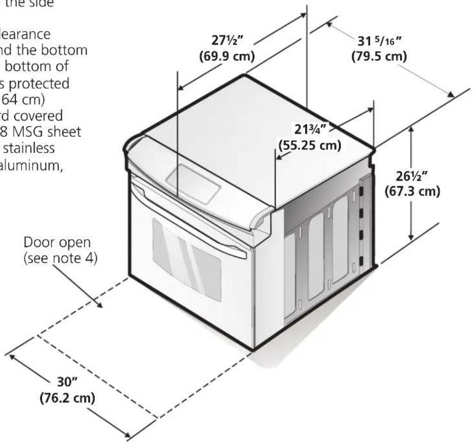
IMPORTANT: Cabinet and countertop width should match the cutout width.

* For cutouts below 22 7/8", appliance will slightly show out of the cabinet.
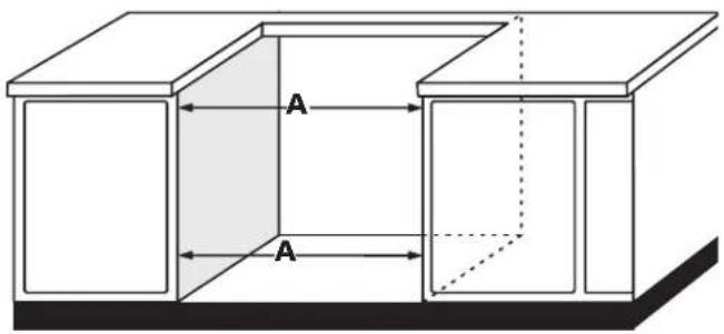
| A. Cutout Width(Countertop and cabinet) | B. Cutout Depth(According to front of cabinet) | C. Height of Cutout |
| 30 ± 1/16"(76.2 ± 0.15 cm) | 21 3/4" (55.2 cm) min22 1/8" (56.2 cm) max | 29" (73.7 cm) |
30" ELECTRIC DROP-IN RANGE INSTALLATION INSTRUCTIONS
1 Electrical Requirements
This appliance must be supplied with the proper voltage and frequency, and connected to an individual, properly grounded branch circuit, protected by a circuit breaker or fuse 40A or 50A.
Observe all governing codes and local ordinances
- A 3-wire or 4-wire single phase 120/240 or 120/208 Volt, 60 Hz AC only electrical supply is required on a separate circuit fused on both sides of the line (red and black wires). A time-delay fuse or circuit breaker is recommended. DO NOT fuse neutral (white wire).
NOTE: Wire sizes and connections must conform with the fuse size and rating of the appliance in accordance with the American National Electrical Code ANSI/NFPA No. 70-latest edition, or with Canadian CSA Standard C22.1, Canadian Electrical Code, Part 1, and local codes and ordinances.
WARNING An extension cord should not be used with this appliance. Such use may result in a fire, electrical shock, or other personal injury. If you need a longer power cord you can purchase a 10' (3 m) power cord kit #903056-9010 by calling the Service Center.
-
These appliances should be connected to the fused disconnect (or circuit breaker) box through flexible armored or nonmetallic sheathed cable. The flexible armored cable extending from the appliance should be connected directly to the junction box. The junction box should be located as shown in Figure 1 or Figure 2 and with as much slack as possible remaining in the cable between the box and the appliance, so it can be moved if servicing is ever necessary.
-
A suitable strain relief must be provided to attach the flexible armored cable to the junction box.
WARNING
Electrical Shock Hazard
• Electrical ground is required on this appliance.
- Do not connect to the electrical supply until appliance is permanently grounded.
- Disconnect power to the junction box before making the electrical connection.
- This appliance must be connected to a grounded, metallic, permanent wiring system, or a grounding connector should be connected to the grounding terminal or wire lead on the appliance.
- Do not use a gas supply line for grounding the appliance.
Failure to do any of the above could result in a fire, personal injury or electrical shock.
⚠️ CAUTION In cold weather shipping and storage conditions, make sure that oven is in final location at least three (3) hours before switching on power. Switching on power while oven is still cold may damage the oven controls.
2 Electrical connection
It is the responsibility and obligation of the consumer to contact a qualified installer to assure that the electrical installation is adequate and is in conformance with the National Electrical Code ANSI/NFPA No. 70-latest edition, or with CSA Standard C22.1, Canadian Electrical Code, Part 1, and local codes and ordinances.
WARNING Risk of electrical shock (Failure to heed this warning may result in electrocution or other serious injury.) This appliance is equipped with copper lead wire. If connection is made to aluminum house wiring, use only connectors that are approved for joining copper and aluminum wire in accordance with the National Electrical Code and local code and ordinances. When installing connectors having screws which bear directly on the steel and/or aluminum flexible conduit, do no tighten screws sufficiently to damage the flexible conduit. Do not over bend or excessively distort flexible conduit to avoid separation of convolutions en exposure of internal wires.
DO NOT ground to a gas supply pipe. DO NOT connect to electrical power supply until appliance is permanently grounded. Connect the ground wire before turning on the power.
WARNING (If your appliance is equipped with a white neutral conductor.)
30" ELECTRIC DROP-IN RANGE INSTALLATION INSTRUCTIONS
This appliance is manufactured with a white neutral power supply and a frame connected copper wire. The frame is grounded by connection of grounding lead to neutral lead at the termination of the conduit, if used in USA, in a new branch circuit installation (1996 NEC), mobile home, recreational vehicles, where local code do not permit grounding trough the neutral (white) wire or in Canada, disconnect the white and green lead from each other and use ground lead to ground unit in accordance with local codes, connect neutral lead to branch circuit-neutral conductor in usual manner see Figure 4. If your appliance is to be connected to a 3 wire grounded junction box (US only), where local code permit connecting the appliance-grounding conductor to the neutral (white) see Figure 3.
NOTE TO ELECTRICIAN: The armored cable leads supplied with the appliance are UL-recognized for connection to larger gauge household wiring. The insulation of the leads is rated at temperatures much higher than temperature rating of household wiring. The current carrying capacity of the conductor is governed by the temperature rating of the insulation around the wire, rather than the wire gauge alone.
Where local codes permit connecting the appliance-grounding conductor to the neutral (white) wire (US Only) (see figure 1):
- Disconnect the power supply.
- In the junction box:
connect appliance and power supply cable wires as shown in Figure 1.

Figure 1 3-WIRE GROUNDED JUNCTION BOX
If oven is used in a new branch circuit installation (1996 NEC), mobile home, recreational vehicle, or where local codes DO NOT permit grounding through the neutral (white) wire, the appliance frame MUST NOT be connected to the neutral wire of the 4-wire electrical system. (see figure 2):
- Disconnect the power supply.
- Separate the green (or bare copper) and white appliance cable wires.
- In the junction box: connect appliance and power supply cable wires as shown in Figure 2.

Figure 2 4-WIRE GROUNDED JUNCTION BOX
Serial Plate Location
You will find the model and serial number printed on the serial plate. The serial plate is located as shown.
Remember to record the serial number for future reference.

3 Range Installation
WARNING The electrical power to the range must be shut off while line connections are being made. Failure to do so could result in serious injury or death.
Countertop Preparation
- The cooktop sides of the range fit over the cutout edge of your countertop.
- If you have a square finish (flat) countertop, no countertop preparation is required. Cooktop sides lay directly on edge of countertop.
- Formed front-edged countertops must have molded edge shaved flat 3/4" (1.9 cm) from each front corner of opening (Figure 3).
- Tile countertops may need trim cut back 3/4"(1.9 cm) from each front corner and/or rounded edge flattened (Figure 3).
- If the existing cutout width is greater than 30 1/16" (76.4 cm), reduce the 34 " (1.9 cm) dimension.

Figure 3
This range is designed to hang from the countertop. It does not rest on the floor.
Be sure the bottom of any wall cabinets are a minimum of 30" (76.2 cm) above the rangetop area.
To eliminate the hazard or reaching over heated surface units, cabinet storage space located above the surface units should be avoided. If cabinet storage is to be provided, the hazard can be reduced by installing a range hood that projects horizontally a minimum of 5" (12.7 cm) beyond the bottom front edge of the cabinets.
Important Note: Door removal is not a requirement for installation of the range, but is an added convenience. The appliance should be placed on a table or the front of the appliance should be raised to be able to fully open the door. Please refer to the Use and Care Guide for oven door removal instructions.

natural_image
Illustration of hands installing or adjusting a door panel with a directional arrow (no text or symbols)- Install base cabinets 30" (76.2cm) apart, and be sure they are plumb and level before attaching to countertop.
- Cut countertop exactly as shown in Figure 1. Shave raised edge level to clear 31 1/2" (81cm) wide rim on rolled edge styled countertops.
- Install the wiring junction box in an adjoining cabinet or under the floor (range has 48"/122cm of conduit). Cut 1-1/4" (3.2cm) hole to bring conduit to the junction box.
- To provide an optimum installation, the top surface of the countertop must be level and flat (lie on the same plane) around the 3 sides that are adjacent to range cooktop. Proper adjustments to make the top flat should be made or gaps between the countertop may occur.
- ⚠️ CAUTION To reduce the risk of damaging your appliance, do not handle or manipulate it by the ceramic glass. Manipulate with care.
- Move range in front of cabinet opening.
- Push the electric conduit through the hole and attach it to the junction box. Leave enough slack in the conduit to allow the range to be pulled forward several inches for service if necessary.
- Oven door is heavy. It is advisable to remove door and eliminate its weight as range is lifted into position. See oven door removal instructions in the Use and Care Guide. NEVER lift the appliance by the control panel doing so may damage the control panel. Lift the range into position on the countertop and make sure the appliance is centered in the cutout opening to be sure that the flanges of the upper side panel are sitting on the countertop to avoid glass breakage.
30" ELECTRIC DROP-IN RANGE INSTALLATION INSTRUCTIONS
4 Anti-tip Bracket installation
A. Preferred Anti-tip installation (All models)
-
The range is equipped with an anti-tip bracket attached to the back of the range with two screws. If countertop thickness is greater than 1/2" (1.3cm), relocate anti-tip bracket to the lower position 1/4" (6.4 mm) below (see figure 4).
-
Anti-slide brackets Installation (Figure 5):
A. Place the range so that it is about 6" out of the cabinet.
B. Insert from below the shoulder screws in the bottom bracket (one on each side)
C. Slide the range into its final position.
D. Position the "L" bracket against the side of the cabinet so that it is retained by the shoulder screws, hold bracket and mark the holes on the inside of the cabinet. Drill pilot holes into cabinet where you just marked (Caution should be taken to avoid drilling through the opposite side of the cabinet). Attach the "L" bracket to the cabinet with the screws provided (don't forget to insert the shoulder screw into the bracket).
E. Repeat steps D on the other side.
- Install the decorative lower trim under the door using the screws provided with the range.
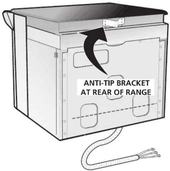
Figure 4

natural_image
Line drawing of an oven with a close-up inset showing the exterior wall detail (no text or symbols)Figure 5
B. Alternate Anti tip installation (All models)
- The range is equipped with two anti-tip "L" brackets located on each side of the range with two screws (see figure 6).

Figure 6
30" ELECTRIC DROP-IN RANGE INSTALLATION INSTRUCTIONS
- Anti-Tip cabinet "L" brackets Installation:
A. Install the anti-tip cabinet "L" brackets as shown on Figure 7, one on each side.
B. Slide the range into its final position. (The anti-tip L brackets attached to the range should be located under the anti-tip cabinet L brackets when the range is at its final position.)
- Install the decorative lower trim under the door using the screws provided with the range.

Figure 7
C. Alternate Anti tip installation (Model with lift-up cooktop only)
- Anti-tip/anti-slide screws installation:
A. Slide the range to its final position. B. Lift the cooktop and secure range burner box to cabinet with screws supplied to prevent range from tipping (Figure 8).
- Install the decorative lower trim under the door using the screws provided with the range.

30" ELECTRIC DROP-IN RANGE INSTALLATION INSTRUCTIONS
5 Checking Operation
Some models have manual controls. Refer to the Owner's Guide and check all controls for correct operation.
Some models are equipped with an electronic oven control. Each of the functions has been factory checked before shipping. However, it is suggested that you verify the operation of the electronic oven controls once more. Refer to the Owner's Guide for operation. Follow the instructions for the Clock, Timer, Bake, Broil, Convection (some models) and Clean (some models) functions.
Bake—After setting the oven to 350^ F ( 177^ C) for baking, the lower element in the oven should become red.
Broil—When the oven is set to BROIL, the upper element in the oven should become red.
Clean (some models)—When the oven is set for a self-cleaning cycle, the upper element should become red during the preheat portion of the cycle. After reaching the self-cleaning temperature, the lower element will become red.
Convection (some models)—When the oven is set for convection baking or roasting, both elements cycle on and off alternately and the convection fan will turn. The convection fan will stop turning when the oven door is opened during convection baking or roasting.
IMPORTANT NOTE: A fan inside the upper rear part above the oven (some models) provides additional cooling of the oven electrical and electronic components. The fan will continue to run after the oven has been operating at high temperatures.
Model and Serial Number Location
The serial plate is located along the side of the oven door in the open position.
When ordering parts for or making inquires about your oven, always be sure to include the model and serial numbers and a lot number or letter from the serial plate on your oven.
Before You Call for Service
Read the Avoid Service Checklist and operating instructions in your Owner's Guide. It may save you time and expense. The list includes common occurrences that are not the result of defective workmanship or materials in this appliance.
Refer to the warranty in your Owner's Guide for our toll-free service number and address. Please call or write if you have inquiries about your product and/or need to order parts.
natural_image
Illustration of hands installing or adjusting a door panel with a tool (no text or symbols visible)natural_image
Line drawing of a kitchen oven with an open lid and a magnified inset showing the interior structure (no text or symbols)Figura 5
Figura 7


- INSTALLATION INSTRUCTIONS 30" ELECTRIC DROP-IN RANGE
- Table of Contents
- Important Notes to the Installer
- Important Note to the Consumer
- 30" ELECTRIC DROP-IN RANGE INSTALLATION INSTRUCTIONS
- IMPORTANT SAFETY INSTRUCTIONS
- FOR MODELS WITH SELF-CLEAN FEATURE:
- Tip Over Hazard
- Cutout Dimensions
- NOTES:
- Electrical Requirements
- Observe all governing codes and local ordinances
- WARNING
- Electrical Shock Hazard
- Electrical connection
- Where local codes permit connecting the appliance-grounding conductor to the neutral (white) wire (US Only) (see figure 1):
- Serial Plate Location
- Range Installation
- Countertop Preparation
- Anti-tip Bracket installation
- Preferred Anti-tip installation (All models)
- Alternate Anti tip installation (All models)
- Alternate Anti tip installation (Model with lift-up cooktop only)
- Checking Operation
- Model and Serial Number Location
- Before You Call for Service
Brand : FRIGIDAIRE
Model : FFED3025LB
Category : Frying Pan