
Bully2000-240618 - Chopper ADE - Free user manual and instructions
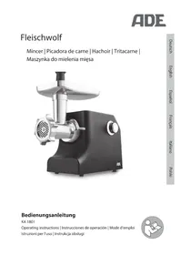
Find the device manual for free Bully2000-240618 ADE in PDF.


| Product Type | Electric Meat Mincer/Meat Grinder |
| Brand | ADE |
| Model | Bully2000-240618 |
| Power Supply | 220-240 V AC, 50/60 Hz |
| Power Consumption | 500 W |
| Dimensions (L x W x H) | 240 x 180 x 250 mm |
| Weight | 3.2 kg |
| Housing Material | Stainless steel and plastic |
| Cutting Plate Material | Stainless steel |
| Blade Material | Stainless steel |
| Capacity (Max per batch) | 1.5 kg |
| Minching Plate Hole Sizes | Fine (3 mm), Medium (5 mm), Coarse (8 mm) |
| Functions | Minching, Sausage stuffing (with included attachment), Reverse function |
| Safety Features | Overload protection, Non-slip feet, Safety lock for bowl |
| Cleaning | Detachable parts dishwasher safe (except motor base) |
| Accessories Included | 3 cutting plates, 2 stuffing tubes, Food pusher, Cleaning brush |
| Spare Parts Availability | Yes, through ADE service |
| Warranty | 2 years |
Frequently Asked Questions - Bully2000-240618 ADE
User questions about Bully2000-240618 ADE
0 question about this device. Answer the ones you know or ask your own.
Ask a new question about this device
Download the instructions for your Chopper in PDF format for free! Find your manual Bully2000-240618 - ADE and take your electronic device back in hand. On this page are published all the documents necessary for the use of your device. Bully2000-240618 by ADE.
USER MANUAL Bully2000-240618 ADE
Burger forming machine

natural_image
Technical line drawing of a mechanical device with no visible text or symbolsBully2000-230
Bully2000-240618-Rev002-UM-en
TABLE OF CONTENTS
- FOREWORD 2
1.1 Introduction....2
1.2 Intended Use 2
1.3 Residual risks 3 - OVERVIEW OF THE MACHINE....3
- INSTALLATION AND COMMISSIONING 5
3.1 Scope of delivery 5
3.2 Unpacking 6
3.3 Setting up the machine....6
3.4 Assembly of the conveyor belt 7
3.5 Mounting the wiper 7
3.6 Inserting the squeegee 7
3.7 Connection of the foot switch 8
3.8 Connection to the power supply 8
3.9 Electrical fuses 8
3.10 Safety precautions 8
3.11 Acceptance test....9 - USING THE BURGER FORMING MACHINE.... 10
4.1 Turn on the machine.... 10
4.2 Turn off the machine....10
4.3 Secure the machine against unauthorized switching on.... 10
4.4 Start manual operation 10
4.5 Stopping manual operation.... 10
4.6 Start operation using a foot switch.... 10
4.7 Regulate speed 10
4.8 Filling product and production.... 11 - LOAD RELEASE PAPER 12
- ADJUST PRODUCT THICKNESS AND WEIGHT 13
- CLEANING AND MAINTENANCE 15
- TRAINING 18
- DISPOSAL 18
- GUARANTEE 18
- TECHNICAL DATA.... 19
- DECLARATION OF CONFORMITY 20
- WIRING DIAGRAMS 21
1. FOREWORD

This symbol means: "Observe the instructions for use". Read the instructions for use carefully and follow the instructions contained therein. Keep the instructions for use for future reference.
This manual was written in accordance with the Machinery Directive in its current version.
The manufacturer wants to inform the customer about the basic operating principles, maintenance requirements and safety devices of the machine in a clear and easy-to-understand form in order to ensure a long service life and trouble-free operation of the machine.
The burger forming machine is subject to continuous improvements, which, however, does not affect the instructions and information provided in this manual.
Before using the burger forming machine, you must read this manual carefully.
If this manual becomes too worn over time or is lost, a copy should be requested from the manufacturer immediately.
The majority of accidents and injuries when using the machine are due to inadequate knowledge of its functions and safety devices. Before starting to work with the machine, you should therefore read the instructions and information contained here carefully.
1.1 Introduction
The burger forming machines are designed according to applicable safety standards. For this reason, you will find the "CE" mark on each of our burger forming machines, which certifies compliance with the above requirements.
1.2 Intended Use
This burger forming machine is used to form burger patties (or, when used together with the ball former, to form meat, fish or vegetable ball patties). The grinded food is pressed through a squeegee into a rotating forming drum. Afterwards, the burger patty can be automatically covered with a release paper ^1 . Then the patties or the burger patty blanks are pressed out of the mould and fall onto the conveyor belt. The conveyor belt transports the burger patty / ball blanks away from the drum.
The machine is equipped with a 130 mm diameter patty mould. The product thickness can be continuously adjusted (only when the machine is at a standstill) up to a thickness of 32 mm. Up to 1300 patties or 2600 ball blanks can (theoretically) be formed per hour.
Use the burger forming machine only for the purpose for which it was designed.

Frozen foods must not be processed with the burger forming machine.
Failure to observe the safety instructions can seriously damage the machine and possibly void any existing warranty claims.
The machine may only be used in its original condition and with original parts. Dismantling the protective devices is not permitted. In the event of damage to protective devices, the machine must be taken out of operation immediately and ADE must be informed for the purpose of renewal or replacement delivery.
1.3 Residual risks
Despite extensive safety precautions on the machine, there are still residual risks for the operator when working with the machine on a daily basis. These occur particularly in the area of rotating parts. To warn of the remaining risks, the following warning signs were placed on the machine:
| symbol | Meaning |
 | Warning of risk of cuts |
 | Hand injury warning |
- OVERVIEW OF THE MACHINE


| No. | Designation |
| 1 | Lid |
| 2 | funnel |
| 3 | Drum cover |
| 4 | Paper dispenser (optional) |
| 5 | Drum ring |
| 6 | (form) drum |
| 7 | scraper |
| 8th | Driven pulley |
| 9 | Free-running pulley |
| 10 | conveyor belt |
| 11 | Footswitch |
| 12 | Stop button |
| 13 | Machine housing |
| 14 |
| No. | Designation |
| 15 | Lid holder |
| 16 | Manual operating selector switch / foot switch |
| 15 | Lid holder |
| 17 | Speed controller |
| 18 | Magnetic sensor - lid |
| 19 | Magnetic sensor - protective flap |
| 20 | Magnetic sensor - drum |
| 21 | Display of the mains voltage |
| 22 | Display of operation |
| 23 | Main switch |
| 24 | Connection for foot switch |
3. INSTALLATION AND COMMISSIONING
3.1 Scope of delivery
The burger forming machine is delivered partially assembled. The scope of (optional) delivery includes:
operation manual
Release paper (D) – (optional)
Burger forming machine
Wiper (E)
Squeegee (A)
Funnel (F) - (factory assembled)
Conveyor belt (B) (short version)
(Form) drum (G) - (factory assembled)
Sliding plate for conveyor belt (C) (short version)
Cover (H) - (factory fitted)
Footswitch (I)

natural_image
Collection of industrial equipment and components labeled A through H, including metallic tanks, pipes, and a fan-like structure (no text or symbols beyond labels)3.2 Unpacking
natural_image
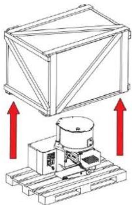
Technical diagram showing a crane lifting a box and a mechanical device with red arrows indicating upward motion (no text or symbols present)- When you receive the machine, examine the packaging and check whether the machine was delivered in perfect condition.
- Remove the screws at the bottom of the packaging and lift off the packaging walls.
- Check the contents of the packaging to ensure they match the information on the delivery note.
- Also ensure that the machine is free of any damage that may have occurred during transport.
- If the burger forming machine is damaged, this circumstance must be reported to the transport company in writing within three days from the date of the accompanying documents, detailing the damage discovered.

Packaging materials are recyclable materials and must under no circumstances be disposed of with household waste. Check with local authorities about options for proper disposal.
Local regulations must be strictly adhered to when disposing of waste.
3.3 Setting up the machine

natural_image
Top-down line drawing of a person with hands holding a circular object, no text or symbols presentYou can now lift the machine off the pallet.
- Handle the machine at the bottom of the machine housing as shown in the illustration, preferably with 3 people to ensure maximum safety.
- Set up the burger forming machine on a flat, smooth and vibration-free surface that offers sufficient stability and stability to ensure sufficient safety, taking into account the machine's own weight. The recommended table height should be approximately 70 cm and may vary depending on the height of the operator. Any unevenness can be corrected using the adjustable feet.
- The controls (on/off switch) point towards the operating personnel. In order to ensure pleasant and problem-free operation, cleaning and maintenance of the machine, a space requirement of 4 m^2 should be given.
- The room in which the machine is placed should be dry, well ventilated and free of heat sources.
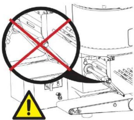
To move the machine, never touch the scraper arm! Remove the scraper arm before moving the device!
3.4 Assembly of the conveyor belt

natural_image
Mechanical assembly diagram showing a lever mechanism with red arrows indicating motion direction (no text or symbols present)
natural_image
Technical line drawing of a mechanical assembly with no visible text or symbols- Place the conveyor belt around the sliding plate that has not yet been installed
- Slide the sliding plate onto the guide pin of the machine and the conveyor belt over the drive roller installed on the machine side.
- Center the conveyor belt.
- Press the conveyor belt down with the slide bar so that the conveyor belt tightens.
3.5 Mounting the wiper
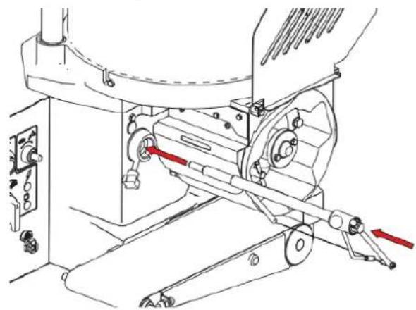
Insert the scraper into the holder.
natural_image
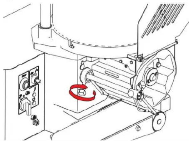
Technical line drawing of a mechanical assembly with no visible text or symbolsTighten the star handle screw.
natural_image
Technical line drawing of a mechanical assembly with no visible text or symbols3.6 Inserting the squeegee
natural_image
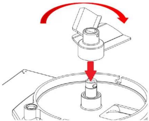
Mechanical assembly diagram showing a rotating component with red arrows indicating motion direction (no text or symbols)Open the lid (1). Place the squeegee on the drive shaft and turn it clockwise until it clicks into the drive shaft.
Note: The squeegee can only be used in one position.
3.7 Connection of the foot switch
natural_image
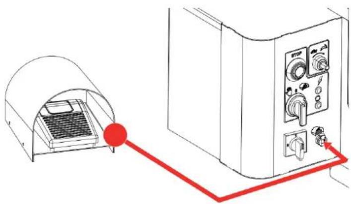
Line drawing of a device with a red arrow pointing to its connection to a control panel (no text or symbols present)Connect the cable of the foot switch (11) to the connection socket on the machine (23).
3.8 Connection to the power supply
The burger forming machine has a Schuko plug. Check whether the existing power network is equipped with a suitable circuit breaker and insert the plug into the socket.

Before connecting to the power supply, ensure that the local power supply and power frequency match those declared on the machine nameplate.
If there is a mismatch, the machine must not be connected, otherwise it could cause damage to the machine and cause fire!
When connecting, make sure that the connection cable is laid in such a way that it does not pose a risk of tripping or falling.
3.9 Electrical fuses
The burger forming machine has the following safety devices:
- Magnetic sensor on the lid axis to check whether the lid is closed (18).
- Magnetic sensor to check whether the protective flap is closed (19).
- Sensor to check whether the drum has been installed (20).
- The burger forming machine stops automatically in the event of a power failure. Restart the machine once the power outage ends.

All fuses are permanently installed on the machine and must not be removed. Unauthorized modifications to the machine turn it into a dangerous device.
Use the device only for the intended areas of use. Improper use and use of the device for purposes not intended can pose risks to the safety and health of people and cause economic damage.
The manufacturer declines all liability for damage caused by improper use of the device, by non-compliance with the information in these operating instructions and by manipulation or modifications to the device without its formal approval.
3.10 Safety precautions
- The burger forming machine may only be operated by previously trained personnel.
- It must be ensured that children, incompetent and untrained personnel cannot operate the device.
- It is forbidden to operate the machine under the influence of alcohol or drugs.
-
To avoid the risk of getting caught on moving parts of the machine, wear tight-fitting clothing. Long hair should be tied in a braid or worn under a hair net.
-
Do not wear rings, bracelets and/or necklaces.
- Never leave the machine unattended while it is in operation.
- When performing any type of maintenance work, unplug the machine from the power supply.
- Never clean the machine under running water or a basin of water.
- If you notice any unusual noises or smells coming from the machine, switch it off immediately, unplug it and contact your customer service center.
- Never use the machine with a damaged plug or cable. If you discover a defect, shut down the machine immediately and have it repaired by the manufacturer or one of the authorized service partners.
- Replacing the power cable may only be carried out by authorized and trained persons.
3.11 Acceptance test
Before acceptance testing, the hopper and lid, the conveyor belt and a forming drum must be assembled.
- Check whether all components of the burger forming machine have been assembled correctly.
- Close the lid (1) and the drum cover (3).
- Insert the plug into the socket.
- Set the main switch (23) to "I".
- Indicator light (21) must light up.
- Set the operating selector switch (16) to "Manual" and check whether the machine can actually be switched on.
- Indicator light (22) must light up.
- Check the direction of rotation of the conveyor belt (10) (direction of arrow).
- Press the stop button (142) and check whether the machine can actually be switched off.
- Check whether the machine switches off when the lid (1) is opened.
- Check that the machine switches off when the drum cover (3) is opened.


If you notice any malfunctions, put the machine out of operation immediately clearly mark it as "DEFECTIVE" and inform your service partner!
The machine cannot be switched on without the forming drum inserted. However, this is not a safety-relevant function, but simply prevents unwanted contamination of the machine.
4. USING THE BURGER FORMING MACHINE
4.1 Turn on the machine
To switch on, turn on the main switch (23).
4.2 Turn off the machine
In the event of interruptions in operation and every time you leave the workplace, the machine must be switched off using the main switch (23).
4.3 Secure the machine against unauthorized switching on
During maintenance work and when inserting/replacing the burger mold, the machine must be secured against unauthorized switching on. To do this, press the yellow lock on the main switch (23) in the 0 position and secure it with a small padlock.
4.4 Start manual operation
Set the operating selector switch to "manual" operation ( ) The machine starts running.
4.5 Stopping manual operation
To stop manual operation, press the red stop button (12).
4.6 Start operation using a foot switch
Set the operating selector switch to "foot operation" ( ). As soon as you press the foot switch, the machine starts running. The machine stops as soon as you stop pressing the foot switch. "Foot operation" is still active. When you press the foot switch, the machine starts running again.
4.7 Regulate speed
By turning the speed control you can continuously vary the production speed.
| symbol | Meaning |
 | Slow machine operation |
 | Fast machine operation |
4.8 Filling product and production
Open the lid (1) and put the minced food into the funnel (2). Close the lid. Switch the machine on at the main switch (23).
Select the desired operating mode (16).
The product falls onto the conveyor belt and is carried away by the drum. Remove the finished product from the conveyor belt by hand in a timely manner or adjust the subsequent production machine to fit the burger forming machine.

natural_image
Technical line drawing of a mechanical device with red directional arrows indicating movement or force (no text or symbols present)If necessary, the wire of the scraper must be freed from product residues during operation. To do this, if necessary, move the scraper once to the right and left during operation.
5. LOAD RELEASE PAPER
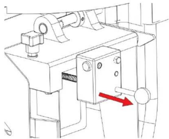
- Remove the optional paper holder by pressing the button (1) and pulling the paper holder out of the guide

natural_image
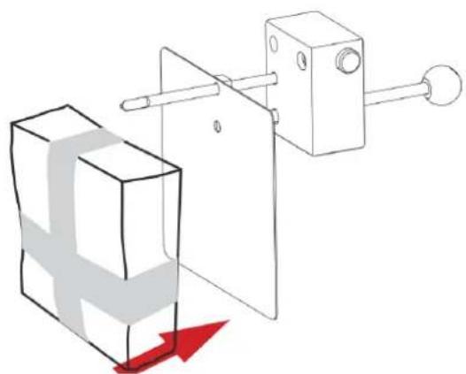
Technical line drawing of a mechanical device with a red directional arrow indicating motion or force (no text or symbols present)- Tension the compression spring. Place the paper pad on the support rod and then remove the banderoles and the cover cardboard.
natural_image
Diagram of a mechanical assembly with a block and lever mechanism, showing a red arrow indicating motion (no text or symbols present)- Insert the paper holder into the guide until it clicks into place. Press the button (2). The spring pushes the stack of paper forward.
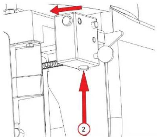
- Release the lock on the paper holder by pulling the lever (3) up and then pressing the entire paper insert against the drum.

- Start the machine. If the product is not positioned correctly under the product, turn the star handle screw (4) to position the paper correctly under the product.

6. ADJUST PRODUCT THICKNESS AND WEIGHT
The machine is preset by the manufacturer. If you want to change the thickness of the product and thus the weight, first switch off the machine using the main switch (16).
Flip the drum cover up.

natural_image
Mechanical assembly diagram showing a motor with rotating arm and guide rails (no text or symbols)Turn the drum ring clockwise and pull the drum off the drive shaft.

natural_image
Technical line drawing of a mechanical component with a red arrow indicating rotation or direction (no text or symbols)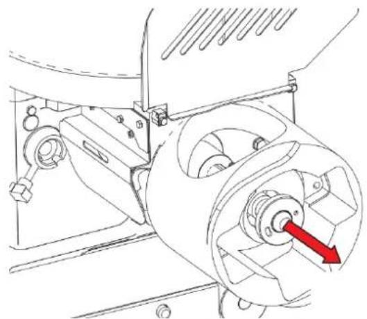
natural_image
Technical line drawing of a mechanical assembly with a red arrow indicating a component (no text or symbols present)Loosen the locking screw that holds the white regulating disk in place.

natural_image
Diagram of a mechanical component with a red circular arrow indicating rotational direction (no text or symbols)Turn the white control dial to change the product thickness.
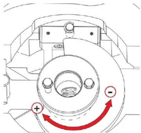

There is a spring in the forming drum that tensions when the regulating disk rotates. If you over-tighten the adjusting disk pin, the spring relaxes and can trap your finger!
Tighten the locking screw (A) again.
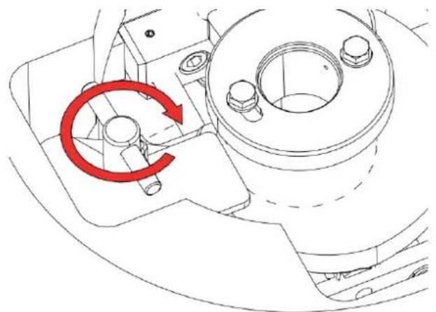
natural_image
Technical line drawing of a mechanical component with a red circular arrow indicating rotational motion (no text or symbols)Reinstall the drum.

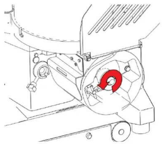
natural_image
Technical line drawing of a mechanical assembly with a red arrow pointing to a component (no text or symbols present)The drum is correctly installed when the drum ring clicks into the slot at the end of the drive shaft.
natural_image
Technical line drawing of a mechanical assembly with a red circular component (no text or symbols)7. CLEANING AND MAINTENANCE
For hygienic reasons, the burger forming machine must always be clean. It must be completely cleaned at the end of each working day and every time the food and/or type of meat is changed (e.g. from pork to beef or poultry).
All parts and cavities that come into contact with the food and where deposits can form must be cleaned.
Cleaning the burger forming machine is exclusively reserved for trained people.

Before cleaning, unplug the machine from the power supply!
Never clean the burger former or its parts in the dishwasher!
Exception: The conveyor belt (without the sliding plate!) and the forming drum can be cleaned in the dishwasher.
Under no circumstances use sodium-hypochlorite-based solutions or abrasive detergents as they would irreparably damage the machine's surfaces. Never use solvents, thinners or alcohol, etc. for cleaning.
The cleaning of the burger former with harmful products liable to affect the health of either operators or customers is strictly prohibited. Only use products with a pH value of 7-8 for cleaning.
Clean the structure of the machine with soft cloths, sponges, and rinse with water frequently. Finally dry with soft and dry cloths. If drying is insufficient, there is a risk of flash rust forming.

Under no circumstances must the machine or parts of it be cleaned with a powerful water jet, high-pressure or steam jet cleaner!
It is possible to rinse the machine with running water from the water hose.
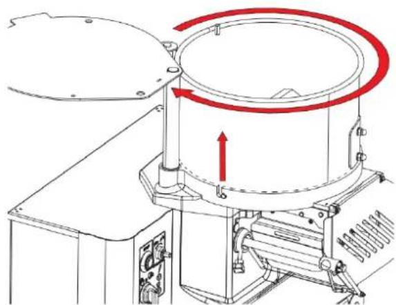
Removing the funnel
Open the lid. Turn the funnel clockwise and lift it off.
natural_image
Technical line drawing of a mechanical device with red motion arrows indicating rotational flow (no text or symbols)Turn the funnel counterclockwise and lift it off.

natural_image
Technical line drawing of a mechanical device with a red upward arrow indicating motion or force (no text or symbols present)Removing the squeegee
Turn it counterclockwise and lift it off.

natural_image
Technical line drawing showing mechanical assembly with red arrows indicating rotation or movement (no text or symbols)Removing the conveyor belt
Raise the front end of the conveyor belt approximately 30^ to 40^ .

natural_image
Mechanical assembly diagram showing a conveyor belt with a red upward arrow indicating motion (no text or symbols present)Pull the conveyor belt with the sliding plate off the machine.

natural_image
Mechanical assembly diagram showing a shaft and roller with red directional arrows indicating motion (no text or symbols)Remove the forming drum
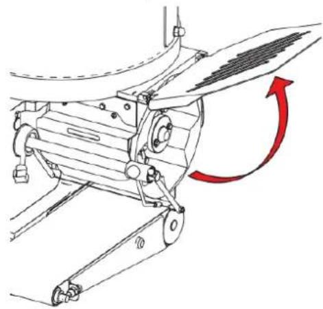
Flip the drum cover up.
natural_image
Mechanical assembly diagram showing a lever mechanism with a red curved arrow indicating rotational motion (no text or symbols present)Turn the drum ring clockwise and pull the drum off the drive shaft.

natural_image
Technical line drawing of a mechanical component with a red arrow indicating rotation or direction (no text or symbols)
natural_image
Technical line drawing of a mechanical assembly with a red arrow indicating direction (no text or symbols present)Remove wiper
Loosen the star handle screw.

natural_image
Technical diagram of a mechanical device with red spiral components and a magnified inset showing internal structure (no text or symbols)Pull the wiper out of the holder.

natural_image
Technical line drawing of a mechanical assembly with red arrows indicating motion direction (no text or symbols)Cleaning the dismantled parts
Clean the dismantled parts only with hot water and a neutral cleaning agent. Then dry the parts well.
Assembly of the cleaned parts
To reassemble the cleaned parts, proceed in the reverse order as described previously. The following must be taken into account:
Put on the funnel
Mount the funnel so that the magnet holder is positioned next to the lid axis.
Insert squeegee
Make sure that the squeegee is completely inserted onto the drive shaft and locks into the drive shaft when twisted.
Note: The squeegee can only be used in one position.
Insert drum
The drum is correctly installed when the drum ring clicks into the slot at the end of the drive shaft.

natural_image
Technical line drawing of a mechanical assembly with a red arrow pointing to a component (no text or symbols present)
natural_image
Technical line drawing of a mechanical assembly with a red circular component and rotating shaft (no text or symbols)8. TRAINING
During the installation of the burger forming machine, the adult operator of the machine must be adequately trained in the areas of use - cleaning - maintenance, paying particular attention to the dangers arising from improper use.
The training must be carried out by the person entrusted with the installation of the machine and who has sufficient knowledge of the EC standards in mechanical engineering.
9. DISPOSAL

Old electrical devices do not belong in household waste. Devices with this marking may not be disposed of as residual waste, but must be recycled.
10. GUARANTEE
ADE will repair or replace this product if it has failed due to poor quality workmanship or defective materials within 1 year from the date of sale (proof of purchase is required).
All moving parts such as scrapers, conveyor belts, squeegees, drums, etc. are excluded from this.
The warranty does not cover external normal wear and tear or damage caused by accident or misuse.
The warranty does not apply to devices that have been opened by unauthorized persons.
The customer's legally regulated rights are in no way affected by this guarantee agreement.
The dealer from whom you purchased the machine is responsible for complaints.
- TECHNICAL DATA
| Model | Bully2000 |
| Double mold drum | 2x ∅ 38 mm |
| (max.) product strength | max. 27 mm |
| Funnel volume | 40 litres |
| Conveyor belt length: | 900mm |
| Dimensions of the machine | |
| Width : | 618 mm (without conveyor belt boom) |
| Depth: | 637mm |
| Height: | 629mm |
| Performance | 0.75kW |
| own weight | 65kg |
| Type of current | 230V, 50Hz |
| IP-Protection (Machine) | IP65 |
| IP- Protection (Switch) | IP69 |
| Optional: | |
| Ball forming drum | Various diameters |
| Funnel, large | 40 l |
| Conveyor belt, large | 900 mm |
| Mobile base frame |
12. DECLARATION OF CONFORMITY
ADE
CE
EC declaration of conformity
Manufacturer:
ADE Germany GmbH
New Höltigbaum 15
22143 Hamburg / Germany
Person authorized to compile the technical documentation:
ADE Germany GmbH
New Höltigbaum 15
22143 Hamburg / Germany
Type/Model:
Burger forming machine
Bully2000
Serial numbers:
Bully2000-230
62891-xxxxxxxx-00001 until 62891-xxxxxxxx-99999
The above manufacturer declares under sole responsibility that the above machine complies with the requirements of the following EC directives in the currently valid version:
2006/42/EC
Machinery Directive
(OJ L 157, June 9, 2006, p. 24–86)
2014/30/EU
EMC directive
(OJ L 96, March 29, 2014, p. 79 – 106)
2011/65/EU
RoHS directive
(OJ L 174, July 1, 2011, p. 88–110)
Directive 2014/35/EU is complied with in terms of its protection objectives in accordance with Annex I No. 1.5.1 MRL 2006/42/EC.
This declaration only applies to the machine in the condition in which it was placed on the market. The declaration becomes invalid as soon as a change is made to the machine that has not been agreed with the manufacturer.
P. Mack
Hamburg, April 5 ^th , 2023
Managing Director
Location, Date
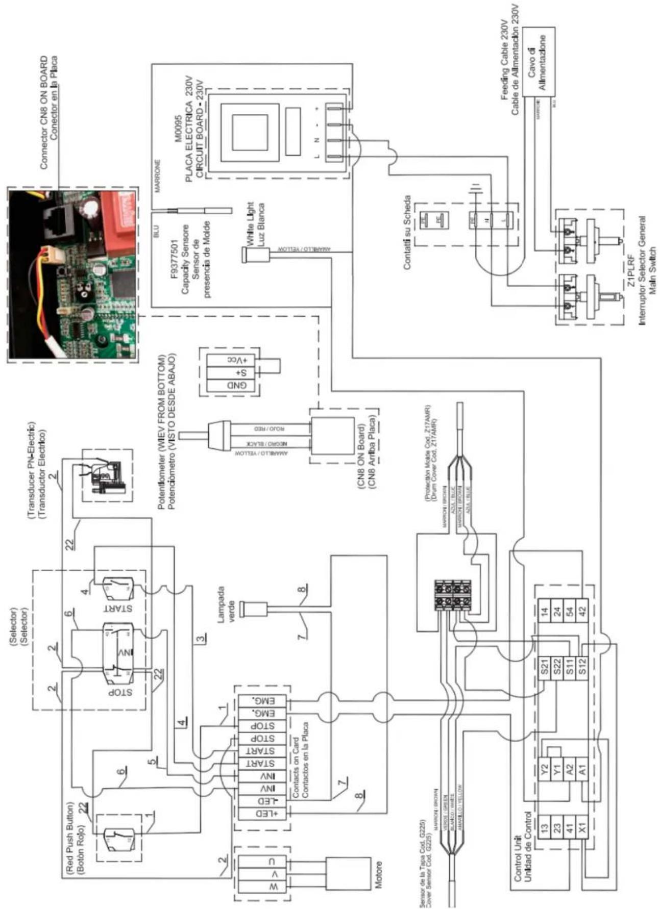
13. WIRING DIAGRAMS
Händler:
Manufacturer:
ADE Germany GmbH
New Höltigbaum 15
22143 Hamburg
+49 40 432 776 - 0
+49 40 432 776 - 10
info@ade-germany.de
www.ade-germany.de
- Burger forming machine
- TABLE OF CONTENTS
- FOREWORD
- Introduction
- Intended Use
- Residual risks
- INSTALLATION AND COMMISSIONING
- Scope of delivery
- Unpacking
- Setting up the machine
- Assembly of the conveyor belt
- Mounting the wiper
- Inserting the squeegee
- Connection of the foot switch
- Connection to the power supply
- Electrical fuses
- Safety precautions
- Acceptance test
- USING THE BURGER FORMING MACHINE
- Turn on the machine
- Turn off the machine
- Secure the machine against unauthorized switching on
- Start manual operation
- Stopping manual operation
- Start operation using a foot switch
- Regulate speed
- Filling product and production
- LOAD RELEASE PAPER
- ADJUST PRODUCT THICKNESS AND WEIGHT
- CLEANING AND MAINTENANCE
- Removing the funnel
- Removing the squeegee
- Removing the conveyor belt
- Remove the forming drum
- Remove wiper
- Cleaning the dismantled parts
- Assembly of the cleaned parts
- Put on the funnel
- Insert squeegee
- Insert drum
- TRAINING
- DISPOSAL
- GUARANTEE
- DECLARATION OF CONFORMITY
- ADE
- CE
- EC declaration of conformity
- WIRING DIAGRAMS
- Manufacturer:
Brand : ADE
Model : Bully2000-240618
Category : Chopper