
X650CS - Drone Dahua Technology - Free user manual and instructions
Find the device manual for free X650CS Dahua Technology in PDF.


| Type de produit | Drone quadrirotor |
| Marque | Dahua Technology |
| Modèle | X650CS |
| Dimensions (plié) | Approx. 35 x 35 x 10 cm |
| Poids (avec batterie) | Environ 1,5 kg |
| Alimentation | Batterie LiPo 14,8 V 5200 mAh |
| Autonomie | Environ 25 minutes |
| Portée de la télécommande | Jusqu'à 1 km en champ libre |
| Caméra | Intégrée, résolution 1080p, stabilisation |
| GPS | Oui, avec retour au point de décollage |
| Fonctions principales | Vol autonome, suivi de sujet, mode orbite |
| Entretien et nettoyage | Nettoyer après utilisation avec un chiffon doux, éviter l'humidité |
| Sécurité | Ne pas voler près de personnes, respecter la réglementation locale |
| Pièces détachées | Hélices, batterie, chargeur, télécommande |
| Réparabilité | Modules remplaçables, assistance technique disponible |
Frequently Asked Questions - X650CS Dahua Technology
User questions about X650CS Dahua Technology
0 question about this device. Answer the ones you know or ask your own.
Ask a new question about this device
Download the instructions for your Drone in PDF format for free! Find your manual X650CS - Dahua Technology and take your electronic device back in hand. On this page are published all the documents necessary for the use of your device. X650CS by Dahua Technology.
USER MANUAL X650CS Dahua Technology
© 2018 ZHEJIANG DAHUA VISION TECHNOLOGY CO., LTD. All rights reserved.
Any or full contents of the user's manual cannot be copied, transmitted, distributed, partially or wholly, by any means, without the prior written notice of ZHEJIANG DAHUA VISION TECHNOLOGY CO., LTD.
Dahua or the third party may reserve the right of the product described in this user's manual. Without the prior written approval of the corresponding party, any person cannot (including but not limited to) copy, distribute, amend, excerpt, reverse compile, disassemble, decode, reverse engineering, rent, transfer or sublicense the software.
Trademark
alhua , , and are the trademarks of registered
trademarks of Dahua and its branch companies in various jurisdictions. Other trademarks or company names mentioned are the properties of their respective owners.
Update and Modification
- In order to enhance the product security and provide better user experience, Dahua may improve the product via software auto update, but Dahua doesn't need to inform in advance and isn't liable to any responsibility.
- Dahua reserves the right to modify any information in this document at any time; the modified contents will be added to the new version without prior announcement. There may be minor differences about some product functions after it is updated.
Document Overview
The manual is to comprehensively introduce function features, structure parameters, installation, dismounting and flight guide etc. of the product.
Applied Model
X650
Application Object
End users
Reading Guide
| Chapter No. | Chapter Name | Main Content |
| 1 | Product Overview | It is to introduce the function features and application scenarios of the product. |
| 2 | Product Component | It is to comprehensively introduce main components of the product. Read the chapter before use; understand product structure and application methods of main components. |
| 3 | Flight Preparation | It is to elaborate the complete flow of aircraft unlock before takeoff. Strictly conform to the installation debugging sequence of the chapter, install each component and make initial debugging before first use.If it is not the first time to use the device, you can select the installation content according to the dismounting situation last time. However, confirm that all the components (unnecessary steps excluded) listed in the chapter have been stably installed. Please conform to the operating steps in this chapter strictly and follow the operating sequence. |
| 4 | Enable Flight | It is to elaborate the complete flow of aircraft formal launch and landing. Complete the preparation steps listed in Chapter 3. Confirm that all the inspection items, including environment and the device itself, conform to flight requirements before enabling flight. Please operate by strictly conforming to the steps described in the chapter; the operation sequence can't be reversed. |
| 5 | End Flight | It is to elaborate the operation steps after aircraft landing. Please operate by strictly conforming to the steps described in this chapter; the operation sequence can't be reversed. |
| 6 | Upgrade | It is to introduce upgrade methods and points of attention. |
| 7 | Appendix 1 | It is to introduce the technical parameters. |
| 8 | Appendix 2 | It is to introduce the indicator definition of the aircraft. |
| 9 | Appendix 3 | It is to introduce the matching method among the components. |
| 10 | Appendix 4 | It is to list possible problems and solutions when using the product. |
Symbol Definition
The following symbol may appear in the document. Please refer to the table below for the respective definition.
| Symbol | Note |
 Danger Danger | It indicates a potentially hazardous situation which, if not avoided, could result in death or serious injury. |
 Warning Warning | It indicates a moderate or low level of potential danger which, if not avoided, could result in minor or moderate injury. |
 Caution Caution | It indicates a potential risk that, if ignored, could result in damage to device, degraded performance, or unpredictable results. |
 Tips Tips | It means that it can help you to solve some problems or save your time. |
 Note Note | It means the additional information, which is the emphasis and supplement of the main body. |
Document Material
The product includes the following document materials. Please search according to your requirements:
- Quick Start Guide
It applies to the first simple flight. Please refer to User's Manual for operation details when it is used for the second time or it has to use some other advanced functions.
Check the paper material in the packaging box or log in www.hovfree.com to obtain the User's Manual.
- User's Manual (this document)
It comprehensively introduces the product function features, structure parameters, installation, dismounting and flight guide etc.
Log in www.hovfree.com and search X650 to obtain the User's Manual.
Revision Record
| No. | Version No. | Revision Content | Release Date |
| 1 | V1.0.0 | First release | 2018.4 |
Important Safeguards and Warnings
The following description is the correct application method of the device. Please read the manually carefully before use, in order to prevent danger and property loss. Strictly conform to the manual during application and keep it properly after reading.

Danger
- Please operate the aircraft in the environment which meets flight conditions, and keep away from no-fly zone.
• After unlocking, operators shall keep at least 5m away from the aircraft.

Warning
- Please transport, use and store the product and all its components in the environment which satisfies the requirements.
- Please strictly conform to operation flows described in the manual when dismantling the device. Please do not dismantle other components privately.

Caution
- Please do not touch the lens of PTZ camera directly. Use hair drier to remove the dust or dirt from the lens surface.
- Please operate the device by strictly conforming to the steps described in the manual; the operation sequence can't be reversed.
- Get to know local laws and regulations before using the aircraft. Please apply to local authorities for flight permission if necessary.
- For the first flight, please adopt loiter mode (before takeoff, it is suggested that GPS satellites are ≥12 and horizontal dilution of precision (HDOP) is ≤1).
- Please make sure that the device antenna has been properly installed before enabling the power of remote control and aircraft. Otherwise, it may cause damages to internal module or shorten the control distance.
Flight Environment

Warning
Please make flight in the environment which meets the following conditions:
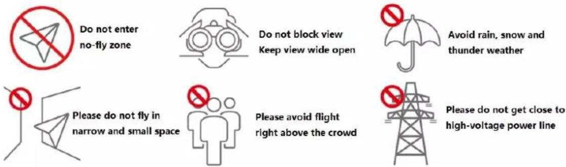
- Keep away from no-fly zone; please do not enter no-fly zone.
- Keep view wide open; make sure the device is flying within field of view; please do not block field of view.
- Please do not fly the aircraft in rain, snow and thunder weather.
- Please do not fly in narrow and small space.
• Try not to fly right above the crowd, in order to prevent personal injury. - Please do not get close to high-voltage power line. Keep more than 10m distance.
Power Requirement
Caution
- The product shall use electric wires (power wires) recommended by this area, which shall be used within its rated specification!
- Products with category I structure shall be connected to grid power output socket, which is equipped with protective grounding.
- Please conform to local electrical safety standards strictly.
- Before operation, please check whether power supply is correct.
- Please use power supply that meets SELV (safety extra low voltage) requirements, and supply power with rated voltage that conforms to Limited Power Source in IEC60950-1. For specific power supply requirements, please refer to device labels.
- Prevent power cord from being trampled or pressed, especially the plug, power socket and the junction extruded from the device.
Battery Points of Attention
Warning
- It has to use the exclusive power adapter provided by Dahua Technology to charge the device. Otherwise, it may damage the battery or lead to other unpredictable consequences.
- Charge the device at a temperature between 0 and 50^ .
- Distinguish positive and negative poles when charging the device, to prevent short circuit.
- Charge and discharge at least once every month; prohibit storing the device without electricity.
- Please do not place the device close to fire source or inflammables.
-
Please do not charge and discharge the device in unattended conditions.
-
Please do not use undesignated battery to the device.
- Please do not dismantle and destroy the battery without permission; water is not allowed to enter the device; man-made damages are not covered by warranty.
- Please do not throw the battery into fire or expose it to high-temperature environment.
- Please do not dismantle, modify or deform the battery.
- Avoid short circuit between positive and negative contacts (please do not place the battery together with the objects such as necklace and hairpin etc. when carrying or storing the battery).
- Please replace new battery timely when it is damaged. Please contact local relevant agency to deal with damaged battery properly, in order to prevent accidents.
- Please charge the battery or discharge it to 50%\~60% remaining capacity if it won't be used for a long time, and place it in a dry and cool environment.
- For air transport, according to relevant aviation requirement, please discharge aircraft battery and remote control battery to below 30%.
- If the battery leaks and the liquid enters eyes accidentally, please do not rub your eyes; wash your eyes with clean water and see a doctor immediately.
! Caution
- It is normal that the battery heats up after it is running for a period of time, because the discharge power is quite big.
- It is normal that the battery heats up when it is being charged.
- The cycle times of aircraft power battery is 300 in normal application situation.
- During charging of power battery, charging is completed when the charger displays "FULL" and beeps continuously. Don't take down batteries before charging is completed.
Application Environment Requirements
- Please do not aim the PTZ camera at strong light (such as lighting, sunlight and so on).
- Please transport, use and store the device within the allowed humidity and temperature range.
- Please do not let any liquid flow into the device.
- Please do not block the device ventilation.
- Please do not press, vibrate or soak the device.
- Please pack the device with original package or material with equivalent quality.
Operation and Maintenance Requirements
Warning
- Please do not dismantle the device privately.
- Please do not touch sensor CCD or CMOS directly; use hair drier to remove dust or dirt from the lens surface.
- Please use soft dry cloth or clean soft cloth to dip a little mild detergent to clean the device.
- Please do not touch or wipe the lens surface directly.
-
Please use the accessories provided by manufacturer and it shall be installed and repaired by professional staffs.
-
Please avoid laser beam radiation to the surface when using laser beam device.
- Please do not provide two or more power supply modes to the device at the same time; otherwise, it may damage the device.
- Max 1 aircraft is allowed to fly in the same area at the same time.
- Please make sure that there is no occlusion above the flight.
Privacy Protection Notice
As the device user or data controller, you might collect personal data of others' such as face, fingerprints, car plate number, Email address, phone number, GPS and so on. You need to be in compliance with the local privacy protection laws and regulations to protect the legitimate rights and interests of other people by implementing measures include but not limited to: providing clear and visible identification to inform data subject the existence of surveillance area and providing related contact.
About the Manual
- The Manual is for reference only. If there is inconsistency between the Manual and the actual product, the actual product shall prevail.
• We are not liable for any loss caused by the operations that do not comply with the Manual. - The Manual would be updated according to the latest laws and regulations of related regions. For detailed information, see the paper User's Manual, CD-ROM, QR code or our official website. If there is inconsistency between paper User's Manual and the electronic version, the electronic version shall prevail.
- All the designs and software are subject to change without prior written notice. The product updates might cause some differences between the actual product and the Manual. Please contact the customer service for the latest program and supplementary documentation.
- There still might be deviation in technical data, functions and operations description, or errors in print. If there is any doubt or dispute, please refer to our final explanation.
- Upgrade the reader software or try other mainstream reader software if the Guide (in PDF format) cannot be opened.
- All trademarks, registered trademarks and the company names in the Manual are the properties of their respective owners.
- Please visit our website, contact the supplier or customer service if there is any problem occurred when using the device.
- If there is any uncertainty or controversy, please refer to our final explanation.
Legal Statement...... I
Preface....II
Important Safeguards and Warnings ...... V
1 Product Introduction....1
1.1 Overview ...... 1
1.2 Functional Features .... 1
2 Structure....3
2.1 Aircraft....3
2.1.1 Product Dimensions....3
2.1.2 Structural Component....5
2.2 Airborne Device....6
2.2.1 The 2MP Visible Light PTZ Camera....6
2.2.2 Structural Component....8
2.3 Remote Control 9
2.3.1 Dimensions 9
2.3.2 Structural Component.... 10
2.3.3 Buttons.... 14
2.3.4 Operation Interface....16
3 Flight Preparation.... 25
3.1 Unpack 25
3.2 Check Remaining Power 25
3.2.1 Aircraft.... 26
3.2.2 Remote Control.... 27
3.3 Charging....27
3.3.1 Aircraft Battery Charging 28
3.3.2 Remote Control Charging.... 29
3.4 Prepare Airborne Device....29
3.4.1 Demount PTZ Camera 29
3.4.2 Install PTZ Camera.... 30
3.5 Prepare Aircraft 30
3.5.1 Unfold Arm....30
3.5.2 Open Antenna.... 31
3.5.3 Remove Sheath.... 31
3.5.4 Open Propeller.... 32
3.5.5 Install and Enable Aircraft Battery 32
3.6 Prepare Remote Control.... 33
3.6.1 Install Micro SD Card.... 33
3.6.2 Open Antenna.... 34
3.6.3 Enable Remote Control Power 34
3.6.4 Confirm Remote Control Mode 34
3.6.5 Set Quick Operation 35
3.7 Enable Aircraft Power 41
3.8 Check and Debugging 41
3.8.1 Remote Control Calibration 41
3.8.2 Accelerometer Calibration 42
3.8.3 Initialization Failure 43
3.8.4 Geomagnetic Abnormity 43
3.8.5 GPS Satellites Insufficiency.... 45
4 Enable Flight.... 47
4.1 Flight Mode 47
4.2 Manual Flight Mode 48
4.2.1 Introduction to Manual Flight Flow 48
4.2.2 Unlock Flight Control 48
4.2.3 Manual Takeoff.... 49
4.2.4 Manual Flight Control 50
4.2.5 Manual RTH and Landing....51
4.2.6 Manual Locking....52
4.3 Intelligent Mode....53
4.3.1 Intelligent Flight Mode 53
4.3.2 Intelligent Locking Mode....57
4.3.3 Intelligent Operation....58
4.4 Intelligent Protection Mechanism 60
4.4.1 Low Battery 60
4.4.2 Out of Control 60
4.5 Remote Control Setting 60
4.5.1 Remote Button User-defined....60
4.5.2 Flight Control Settings 61
4.5.3 Preview Settings....64
4.5.4 Camera Settings 65
4.5.5 General Settings....69
5 End Flight....73
5.1 Turn off Power 73
5.2 Dismantle Air-borne Device....74
5.3 Fold Aircraft....74
5.4 Copy Video of Camera Micro SD Card 75
5.5 Remove Other Components....76
6 Upgrade and Update....77
6.1 Firmware Update....77
6.2 Remote Control Update....77
6.2.1 APP Update 77
6.2.2 Download and Update Offline Map of Remote Control....78
Appendix 1 Main Technical Parameters ...... 79
Appendix 2 Aircraft State Indicator 82
Appendix 3 System Pairing....84
Appendix 4 FAQ....86
Appendix 4.1 FAQ and Solutions of Aircraft....86
Appendix 4.2 FAQ and Solutions of Remote Control....86
Appendix 4.3 FAQ and Solutions of Airborne Device....86
1.1 Overview
This product is a quadrotor drone designed for public security, transportation, firefighting, border defense, agriculture, forest and energy source fields. It provides integrated solutions of aerial video surveillance.
This product consists of aircraft, airborne device and remote control.
- Aircraft: It consists of navigation system, flight control system and power system.
- Airborne device: It consists of the PTZ control system and mission device.
- Remote control: It consists of the remote control system and data chain software.
1.2 Functional Features
Integrated Design
- The aircraft adopts integrated design and neat appearance.
- The remote control integrates the remote control and touch screen together. It is easy to operate and has clear indicator.
Folded Packages
Propeller, arm and antenna adopt folded design, suitable to be carried, transported and stored conveniently.
HD Video
- The shock absorber board and shock absorber ball work together to guarantee PTZ camera stability.
- Industrial 30x optical zoom visible light camera is optional, with professional HD video effect.
- IR thermal camera is optional, suitable for special environments such as fire scene or night environment, so as to guarantee clear video and high restoration.
- The remote control has snapshot button and record button, which are easy to operate and instantly start snapshot and record function.
Accurate Positioning
Built-in GPS system ensures that positioning is accurate and real-time.
Wireless Transmission
- Aircraft has 4 antennas. Connect the remote control and image transmission device to send and receive radio wave signals.
- The remote control has 3 antennas. Connect the aircraft to send and receive radio wave signals.
- Support to insert a general 4G SIM card, connect with the background and transmit real-time images.
Low Electric Quantity Protection
When electric quantity is lower than preset value, trigger low electric quantity protection automatically, including alarm, return home and landing.
Intelligent Battery of Aircraft
- Display remaining electric quantity: Aircraft battery has built-in power indicator light.
- Balanced charging protection function: Automatically balance the aircraft battery cell voltage to protect battery.
- Overcharge protection function: Aircraft battery automatically stops charging when the voltage is full.
- Sleep protection function: Aircraft battery automatically goes to sleep status when there is no operation within 5 minutes.
- Charging temperature protection function: The aircraft battery charging temperature ranges from 0°C to 50°C. Once the temperature is too high, battery automatically stops charging; otherwise, it may result in battery damage.
- Communication: The remote control can get current remaining capacity and voltage information in a real-time way.
Flight Control
- The aircraft adopts quadrotor power system. It can switch among several flight modes and is easy to control the flight direction.
• Maximum take-off weight is 8110g.
Electronic Fence (e-fence)
- Support e-fence function; prevent the aircraft from leaving the specified zone.
- Support customized e-fence settings.
This product mainly consists of aircraft, airborne device and remote control. This chapter introduces the structures of these three components. The detailed operations will be introduced in Chapter 3.

Note
All figures listed below and all dimensions listed here are for reference only. The figure and the dimensions may be slightly different from the user data due to measurement position, measurement accuracy and position indication. Please refer to the actual product for detailed information.
2.1 Aircraft
This part will be introduced when the propellers are installed and the fuselage is fully unfolded. Please refer to "Chapter 3" for details.
2.1.1 Product Dimensions
The unit is mm.

natural_image
Technical line drawing of a quadcopter drone with four propellers and a central body, shown with dimension lines (no text or symbols on the diagram itself)Figure 2-1

Figure 2-2
2.1.2 Structural Component
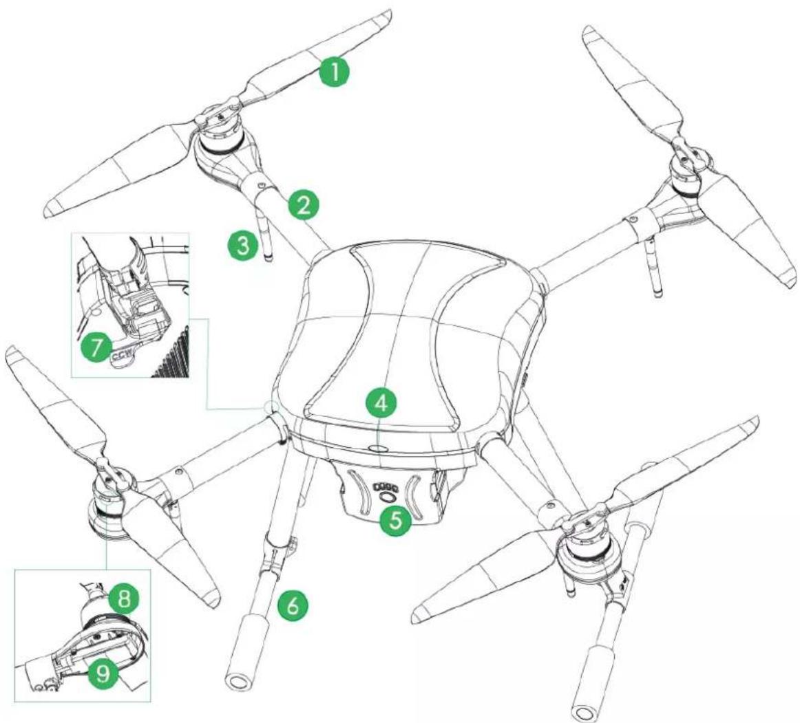
Figure 2-3
| No. | Name | Function |
| 1 | Propeller | High-speed revolution to turn the motor power to propulsive force. There are two pairs of propellers with different structures. Please adjust the installation positions according to the actual situation. |
| 2 | Arm | Fold or unfold. |
| 3 | Antenna | Fold or unfold.2 antennas are to receive the remote control signal.2 antennas are used for wireless image transmission. |
| 4 | Aircraft status indicator | There are two modes: normally on and flashing. It displays five colors: red, yellow, blue, green and purple, to indicate system status, flight mode, upgrade status and etc.NoteRefer to “Appendix 2 Aircraft State Indicator” for indicator light information and definition. |
| 5 | Aircraft battery | After the battery is inserted into the aircraft, electric quantity indicator turns on and shows green. |
| 6 | Landing gear | Fixed under the fuselage, support the aircraft. |
| 7 | Arm wrench | It is used to fold the arm. |
| 8 | Motor | Bring along propeller revolution. |
| 9 | Electronic speed controller | Adopt sine wave driving and boast good acceleration and deceleration performance. |
Table 2-1
2.2 Airborne Device

Note
- This part takes visible light PTZ camera and thermal PTZ camera as an example, and introduces airborne device.
- For detailed info about various airborne devices, please refer to their user's manuals and quick start guides.
The aircraft supports to carry 2MP visible light PTZ camera and various airborne devices.
2.2.1 The 2MP Visible Light PTZ Camera
The unit is mm.
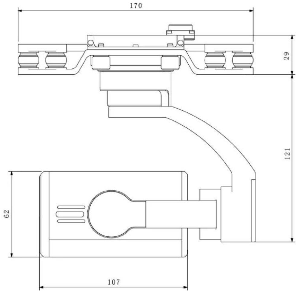
Figure 2-4

Figure 2-5
2.2.2 Structural Component

Figure 2-6
| No. | Name | Function |
| 1 | Shock absorber ball | Reduce PTZ camera vibration during the flight, to get clearer video. |
| 2 | Shock absorber board | |
| 3 | Installation screw | Secure the PTZ camera on the aircraft. |
| 4 | Yaw motor | Control rotation angle of yaw axis of the camera. |
| 5 | Yaw rotation arm | |
| 6 | Roll motor | Control rotation angle of roll axis of the camera. |
| 7 | Roll rotation arm | |
| 8 | Pitch motor | Control rotation angle of pitch axis of the camera. |
| 9 | Camera | Take pictures. |
| 10 | Lens |
Table 2-2
2.3 Remote Control
2.3.1 Dimensions
The unit is mm.
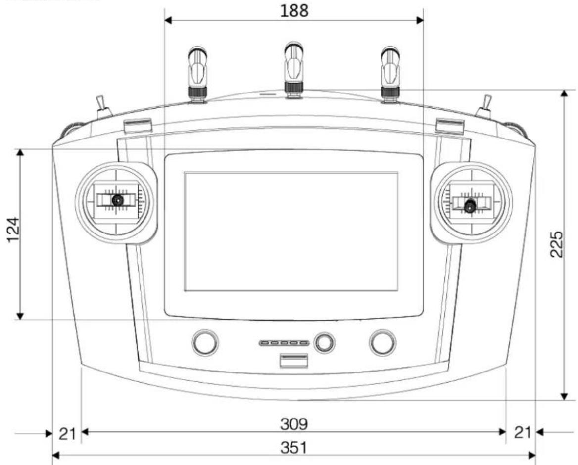
Figure 2-7

Figure 2-8
2.3.2 Structural Component
Front panel, side panel and rear panel of the remote control are shown in Figure 2-9, Figure 2-10 and Figure 2-11.
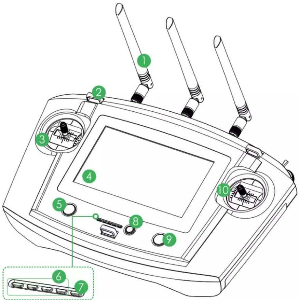
Figure 2-9
| No. | Name | Function |
| 1 | Antenna | Establish the remote control relationship with the aircraft to receive images. One silver antenna is installed in the middle, while two yellow antennas are installed at both sides. |
| 2 | Hanger | Fix the hanger belt. |
| 3 | Left control stick | Control the aircraft flight status. |
| 4 | Touch screen | Set parameters and preview the video. |
| 5 | Customized button | Control the PTZ to return to center and carry out 90° operation with one button. |
| 6 | Battery indicator | Each bar represents 25% battery power. |
| 7 | Charging indicator | Indicator light is on when connecting power to the charging port.Red light is normally on: charging.Yellow-green light is normally on: charging is finished. |
| 8 | One-click return button | Control aircraft to return home automatically. |
| 9 | One-click takeoff/ landing button | Control aircraft to take off and land with one button. Takeoff height is 2m. |
| 10 | Right control stick | Control the aircraft flight status. |
Table 2-3
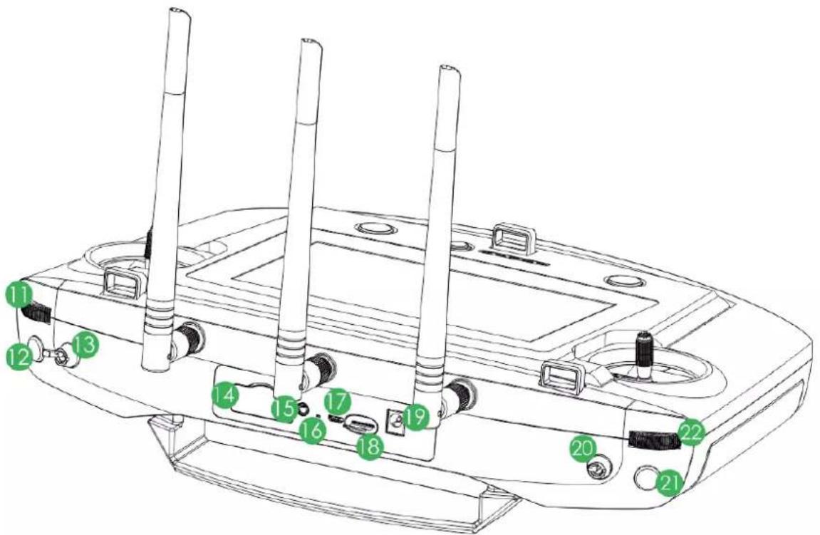
Figure 2-10
| No. | Name | Function |
| 11 | PTZ course scroll wheel | Control horizontal shooting angle of camera lens. |
| 12 | Snapshot | Press this button shortly to snapshot present image. |
| 13 | Flight mode lever | 3-level lever to select flight mode.Upper level: intelligent flight mode. The aircraft flights automatically according to the specified course.Middle level: flight at the specified height. When the throttle lever is at the central mode, the aircraft flights at the same height automatically.Lower level: flight at the specified position. When all levers are at the central mode, the aircraft hovers at the same position. |
| 14 | 4G SIM slot | Support 4G function. |
| 15 | Audio output port | Connect to earphone, sound box and etc. It is to play audio. |
| 16 | Reserved | Reserved function. |
| 17 | Micro-USB port | Insert data cable to connect PC. It is to transmit the data to the PC. |
| 18 | SD slot | Insert SD card: The SD card with the chip is facing down.Insert the card to the slot horizontally.Remove SD card: Press SD card inwards, so SD card pops up a little bit, and can be pulled out. |
| 19 | Power port | Input DC 12V power. |
| 20 | PTZ mode lever | 2-level lever. It is to select PTZ mode.Upper level: Course following mode. The PTZ camera angle changes with aircraft flight direction.Lower level: Course locking mode. No matter what the aircraft flight angles are, the PTZ camera always faces the same degree to shoot. |
| 21 | Record button | Press this button shortly to start recording, and press it again to stop recording. |
| 22 | PTZ pitch scroll wheel | Control vertical shooting angle of camera lens. |
Table 2-4
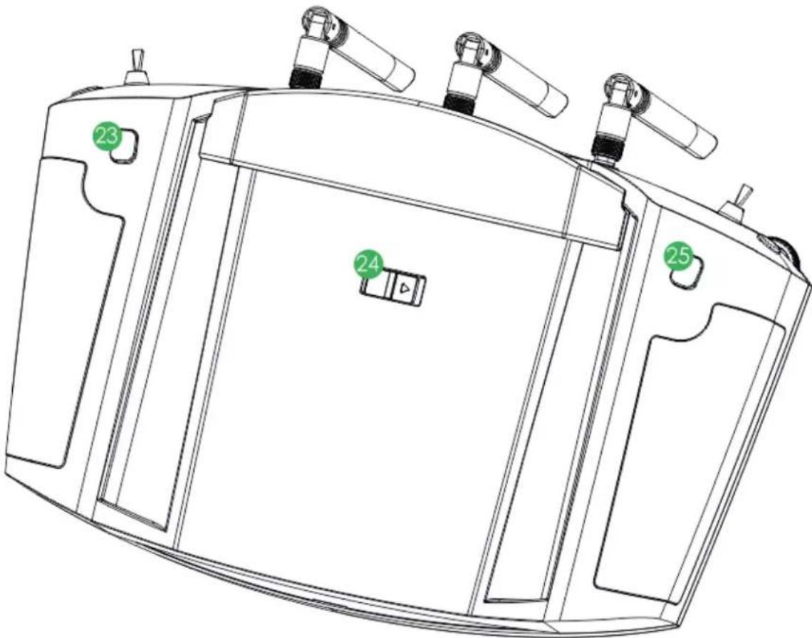
Figure 2-11
| No. | Name | Function |
| 23 | Zoom in button | Short press the button to zoom in the camera.Long press the button, to zoom in until the camera reaches the maximum magnification. |
| 24 | Power switch | Turn on or turn off the remote control.“ON” means to turn on the device, and “OFF” means to turn off the device. |
| 25 | Zoom out button | Short press the button to zoom out the camera.Long press the button, to zoom out until the camera reaches the minimum magnification. |
Table 2-5
2.3.3 Buttons

Note
Refer to "Chapter 4" for the joystick and flight mode lever button information.
2.3.3.1 Scroll Wheel

Note
Besides "PTZ course scroll wheel" and "PTZ pitch scroll wheel", at "Status Bar > Quick Operation > PTZ", control "PTZ Center" and "PTZ 90°" by reference to "3.6.5.2 PTZ".
- PTZ course scroll wheel: control horizontal shooting angle of camera lens, as shown in Figure 2-12.
Scroll wheel turns to the left: PTZ turns to the left. ◇
Scroll wheel turns to the right: PTZ turns to the right. ◇

natural_image
Technical line drawing of a mechanical assembly with mounting holes and directional arrows indicating motion (no text or symbols)Figure 2-12
- PTZ pitching scroll wheel: control vertical shooting angle of camera lens, as shown in Figure 2-13.
Scroll wheel turns to the left: camera lens turns downwards. ◇
Scroll wheel turns to the right: camera lens turns upwards. ◇

natural_image
Technical line drawing of a vehicle front panel with airflow indicators (no text or symbols)Figure 2-13
2.3.3.2 PTZ Mode Lever
Working mode of PTZ camera is controlled with PTZ mode lever, as shown in Figure 2-14.
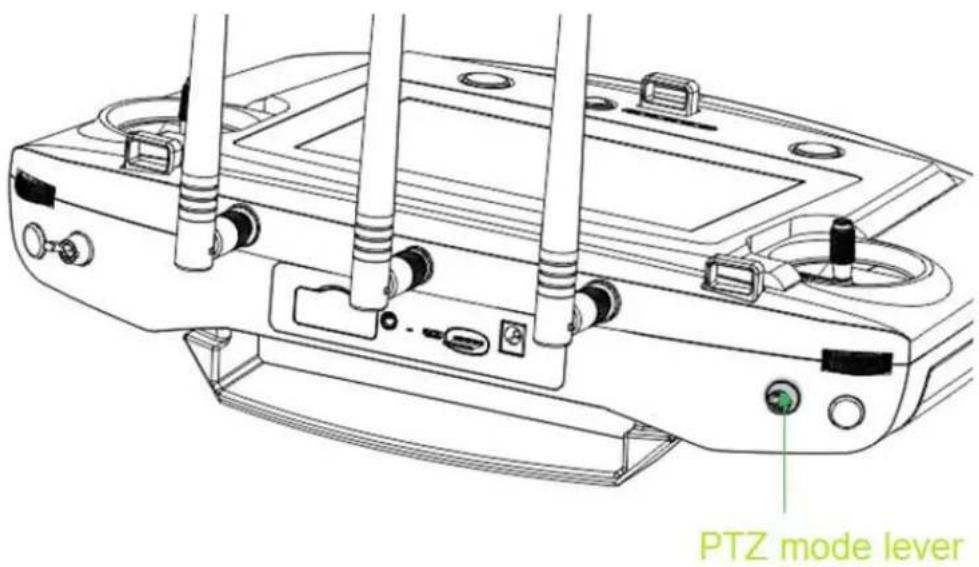
Figure 2-14
2-level lever:
- Upper level: Course following mode. Shooting angle of PTZ camera changes with aircraft flight direction.
- Lower level: Course locking mode. No matter what the aircraft flight angles are, the PTZ camera always faces the same degree to shoot.
- Lever returns to the center: start from any position, move the lever for three times continuously. Shooting angle of PTZ camera will be consistent with aircraft flight direction
2.3.3.3 Shooting

Figure 2-15
- Snapshot: Short press snapshot button to snapshot the present image.
- Record: Short press record button to begin recording video. Short press it again to stop recording.
2.3.4 Operation Interface
After turning on with the remote control, enter main interface. It consists of the following function modules, as shown in Figure 2-16.
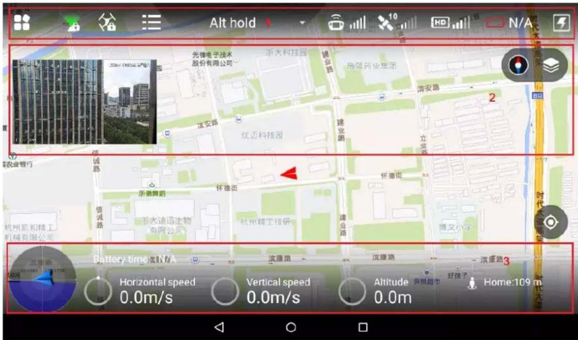
Slide up at any position on the main interface to hide the setting menu, function bar and state bar. Slide down at any position on the main interface to view them again.
| No. | Name | Function |
| 1 | Function setting and state bar | Set the menu and aircraft course; display PTZ mode, flight state list, flight mode, remote control signal intensity, GPS signal intensity, image transmission signal quality, aircraft battery and quick viewing.Please refer to “4.5 Remote Control Setting” for specific setting items and descriptions. |
| 2 | Preview window | Quickly switch video preview and map preview to display prompt information and PTZ control. Please refer to “2.3.4.3 Preview” for details. |
| 3 | State bar | Display remaining flight time, aircraft speed, height and distance from the HOME. Please refer to “2.3.4.2 State Display Bar” for details. |
Table 2-6
2.3.4.1 Function Setting and State Bar

Figure 2-17
| Icon | Name | Function |
 | Settings | Click this icon to enter setting menu.Please refer to “2.3.4.1.1 Setting” for details. |
 | PTZ mode | Display present PTZ mode (PTZ locking or PTZ following mode).: When the PTZ lever is at the lower level, the PTZ camera has locked the course direction. No matter how aircraft angle changes, the PTZ camera is still facing the same direction to shoot.: When the PTZ lever is at the upper level, the PTZ camera direction is flight following mode. The shooting angle changes with the aircraft course angle. |
 | Locking mode | Click this icon to set aircraft course locking or return locking mode.Please refer to “2.3.4.4.2 Locking Mode” for details. |
 | Drone state list | Click this icon, and aircraft state list will pop up.View compass, accelerometer, gyro, remote mode, GPS signal, drone battery and camera SD card remaining/total capacity info. |
| [SYHY] | Flight mode display | Display present flight mode of the aircraft, including intelligent flight, loiter and fixed point mode. |
 | Remote control signal intensity | Display signal intensity of remote control and aircraft. There are max. 5 bars. The more the highlighted bar amount is, the stronger the remote control effect is. |
| [DWDB] | GPS satellite and signal intensity | The number on the left side is the GPS satellite amount.The GPS signal intensity is shown on the right. There are max. 5 bars. The more the highlighted bar amount is, the stronger the remote control effect is. |
 | Image transmission signal quality | Click this icon, and image transmission signal quality frame will pop up. Display general signal quality of image transmission antenna. |
 | Remaining battery of aircraft | Display battery info of the aircraft. Display N/A when the aircraft is not connected; display present aircraft battery percentage after pairing connection. |
 | Quick operation | Click this icon to enter quick entry interface, and set dashboard, PTZ, image transfer and other quick options. Please refer to “3.6.5 Set Quick Operation” |
| for details. |
Table 2-7
2.3.4.1.1 Setting

Click to enter setting interface, as shown in Table 2-8.
| Level 1 Menu | Level 2 Menu | Level 3 Menu | Function |
| Remote Control | Control joystick mode | - | Provide two modes.Please refer to “4.2.4 Manual Flight Control” for details. |
| Remote control calibration | - | Calibrate the remote control.Please refer to “3.8.1 Remote Control Calibration” for details. | |
| Remote pair | - | Pair the remote control and aircraft again.Please refer to “Appendix 3 System Pairing” for details. | |
| Remote button user-defined | - | Indicate A1 button and function of the remote control.Please refer to “4.5.1 Remote Button User-defined” for details. | |
| Flight | Fence enable | - | Enable or disable e-fence.Please refer to “4.5.2.2 Enable Electronic Fence” for details. |
| Fence settings | Fence type | Set e-fence type.Please refer to “4.5.2.1.1 Fence Type” for details. | |
| Fence action | Select fence action.Please refer to “4.5.2.1.2 Fence Action” for details. | ||
| Max height | Set max. height, max. radius and reach distance of the fence.Please refer to “4.5.2.1.3 Other Settings” for details. | ||
| Max radius | |||
| Reach distance | |||
| Preview | Image transmission settings | - | Set preview image size.Please refer to “4.5.3 Preview Settings” for details. |
| Camera | Photo settings | - | Set photo size.Please refer to “4.5.4.1 Photo Settings” for details. |
| Video settings | - | Set relevant parameters of video.Please refer to “4.5.4.2 Video Settings” for details. | |
| Advanced | Image settings | Set brightness, contrast, saturation, sharpness and gamma value.Please refer to “4.5.4.3 Image Settings” for details. | |
| General | Aircraft firmware upgrade | - | Check firmware status and upgrade.Please refer to “6.1 Firmware Update” for details. |
| APP upgrade | - | Check APP status and upgrade.Please refer to “6.2.1 APP Update” for details. | |
| Other | Geomagnetic calibration | Calibrate geomagnetism.Please refer to “3.8.4 Geomagnetic Abnormity” for details. | |
| Accelerometer calibration | Calibrate accelerometer.Please refer to “3.8.2 Accelerometer Calibration” for details. | ||
| Offline map | Add or delete offline map.Please refer to “6.2.2 Download and Update Offline Map of Remote Control” for details. | ||
| Brightness | Adjust brightness of tablet PC.Please refer to “4.5.5.1.3 Brightness” for details. | ||
| Date and time | Set the date and time of remote control.Please refer to “4.5.5.1.4 Date and time” for details. | ||
| Network setting | Set networking mode.Please refer to “4.5.5.1.1 Network Settings” for details. | ||
| Language | Set software language of remote control.Please refer to “4.5.5.1.5 Language” for details. | ||
| Storage setting | View total storage space of Micro SD card and the space occupied by every part.Please refer to “4.5.5.1.2 Micro SD Settings” for details. | ||
| About | Hardware version | Display hardware info. |
Table 2-8
On settings interface, click to return to the previous menu and click to exit settings.
Click it to select locking mode of the aircraft on the popped up dialog box, as shown in Figure 2-18.
Figure 2-18
2.3.4.1.3 Flight State List
Click the icon to display drone state list, as shown in Figure 2-19.
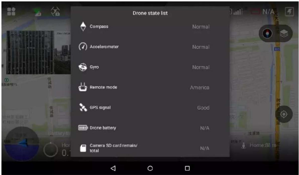
Figure 2-19
View drone state info in a real-time way.
2.3.4.1.4 Quick Operation
Realize quick setting of dashboard, PTZ, image transfer and others. Please refer to "3.6.5 Set Quick Operation" for details.
Click the icon to display quick operation, as shown in Figure 2-20.
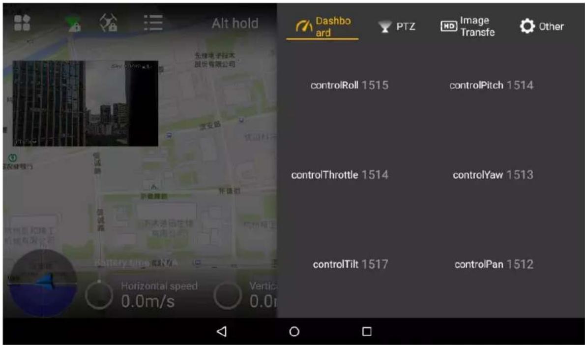
Figure 2-20
2.3.4.2 State Display Bar

Figure 2-21
| Icon | Name | Function |
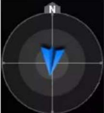 | Aircraft direction and camera lens direction | Blue triangle: it indicates the aircraft direction on the geographic position. |
 | Battery time | Display remaining flight time of the aircraft. It displays N/A when the aircraft is not connected.NoteThis estimated value is for reference only. Actual flight time may be affected by environment and etc., so it may be different from the actual flight time. |
 | Horizontal speed | Horizontal forward and backward speed of the aircraft. It displays N/A when the aircraft is not connected. |
 | Vertical speed | Vertical ascending and descending speed of the aircraft. It displays N/A when the aircraft is not connected. |
 | Altitude | Relative altitude from the takeoff position. It displays N/A when the aircraft is not connected. |
 | Distance from the HOME | Distance between the aircraft and Home. This value is planar projection distance. |
Table 2-9
2.3.4.3 Preview
Click the window at the top left corner, to switch between video preview mode and map preview mode.

Prompt information is displayed on the right side of the icon. Click the icon to view message list.
2.3.4.3.1 Video Preview Mode
Default preview mode is shown in Figure 2-22.
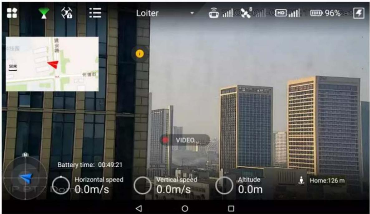
Figure 2-22
- In this mode, the map is displayed in a small window at the top left corner of the preview interface.
- In this mode, the large window displays the real-time image transmitted by the camera to the remote control.
2.3.4.3.2 Map Preview Mode

- In this mode, the image transmitted by the camera to the remote control is displayed in a small window at the top left corner of the preview interface.
• In this mode, the large window displays aircraft position on the map.
Buttons in map preview mode are described as follows:

- Map direction locking button: When it is unlocked, press the map interface with two fingers to rotate the map; when it is locked, map direction cannot be changed.

- Map display mode switching button: Switch to display the map in the form of satellite imagery or 2D image.

- Central button: Switch to current position of the aircraft quickly and center at current position of the aircraft.
2.3.4.4 General Functions
2.3.4.4.1 Set Home Point
Click the icon to set current location of the aircraft to be Home, as shown in Figure 2-24.

Figure 2-24
2.3.4.4.2 Locking Mode
Click the icon to select locking mode of the aircraft on the popped up dialog box, as shown in Figure 2-25.

Figure 2-25

Note
- This chapter elaborates complete flow before the aircraft is unlocked and takes off.
- Please select operation according to the actual situation after the first flight is over, if it is not the used for the first time.

Caution
Please operate by strictly conforming to the steps described in this chapter; the operation sequence can't be reversed.

flowchart
graph TD
    A["Unpack"] --> B["Check remaining power → Please charge in case of low battery"]
    B --> C["Prepare airborne device"]
    C --> D["Prepare aircraft"]
    D --> E["Prepare remote control"]
    E --> F["Enable aircraft power"]
    F --> G["Check debugging → All debugging is normal"]
    G --> H["Start flight"]
Figure 3-1
3.1 Unpack
Take out aircraft, battery and remote control from the packing box.
3.2 Check Remaining Power
Check the remaining power of aircraft battery and remote control. Implement the subsequent steps after confirming that the battery reaches the standard.
Please refer to "3.3 Charging" when the battery is low. Please implement the subsequent steps after charging.
3.2.1 Aircraft
3.2.1.1 Aircraft Battery Check
Short press the aircraft battery indicator button once, and then long press it for 3s, and check the state of indicator lights, as shown in Figure 3-2.

natural_image
Illustration of a hand pressing a button on a human torso, with a green screen displaying four squares (no text or symbols)Figure 3-2
- At normal temperature, the remaining power shall be ≥ 2 .
- The aircraft shall take off with full power when temperature is lower than -10°C.

Note
When the aircraft battery is installed onto the aircraft, battery indicator button is red and battery indicator is green.
3.2.1.2 Aircraft Remaining Power
There are three states for each indicator light of the aircraft battery, which are normally on, flash and off.
The following table describes remaining power percentage in different status. “●” means normally on, “◎” means flash and “○” means off, as shown in Table 3-1.
| No. | Indicator Light Status | Remaining Battery Percentage Range |
| 1 | ●●●●~●●●◎ | 100%~87.5% |
| 2 | ●●●◎~●●●○ | 87.5%~75% |
| 3 | ●●●○~●●◎○ | 75%~62.5% |
| 4 | ●●◎○~●●○○ | 62.5%~50% |
| 5 | ●●○○~●◎○○ | 50%~37.5% |
| 6 | ●◎○○~●○○○ | 37.5%~25% |
| 7 | ●○○○~◎○○○ | 25%~12.5% |
| 8 | ◎○○○~○○○○ | 12.5%~0 |
Table 3-1
3.2.2 Remote Control
3.2.2.1 Remote Control Battery Check
Move the power switch to the arrow location; view the number of indicator lights which are on.

natural_image
Illustration of a hand pressing a smartphone with an arrow indicating action (no text or symbols)
Figure 3-3

Figure 3-4
- At normal temperature, the remaining power shall be ≥ 2 .
- Remaining power shall be ≥ 3 when the temperature is lower than -10^ .
3.2.2.2 Remaining Power of Remote Control
There are two statuses for each indicator light of remote control, which are normally on and off. The following table describes remaining power percentage in different status, “●” means normally on and “○” means off, as shown in Table 3-2.
| No. | Indicator Light Status | Remaining Battery Percentage Range |
| 1 | ●●●●~○●●● | 100%~75% |
| 2 | ○●●●~○○●● | 75%~50% |
| 3 | ○○●●~○○○● | 50%~25% |
| 4 | ○○○●~○○○○ | 25%~0 |
Table 3-2
3.3 Charging

Note
It doesn't need to implement the following chapter if the remaining power is enough.
3.3.1 Aircraft Battery Charging

During charging of power battery, charging is completed when the charger displays "FULL" and beeps. Don't take down batteries before charging is completed.
The entire charging period (from 0 to full) is about 1.5 hours. Charging period is related with remaining power and charging current.

natural_image
Technical line drawing of a device with ports and wiring, no text or symbols presentFigure 3-5
Take out the battery: press the snap joints at both ends of the battery, keep the battery Step 1 horizontal and take it out.
Connect AC: connect charger power wire with charger port, and connect AC power. Step 2
Connect DC: insert charging adapter cable into battery and charger port. Step 3
Select charging mode: open charger switch, turn the black button, select BLC and short Step 4 press the black button. The value displayed by LED nixie tube bounces and flashes.
Step 5 Select charging current: turn the button to adjust current, whose proposed value is 12A.
After adjustment, short press the black button to confirm.
____ Open the battery: short press the battery indicator light button once, and then long Step 6 press it for 3 seconds, to turn on the electric quantity indicator light and check present battery.
Long press the button to start charging and wait for the charger prompt. It means Step 7 charging is completed when the charger beeps for 5 times and LED nixie tube displays FULL.

natural_image
Simple diagram showing a green rectangular object above a gray circular ring, with no text or symbols present.Figure 3-6
____ After charging is completed, disconnect it from the power socket, and then disconnect Step 8 all other cables.
3.3.2 Remote Control Charging
The entire charging period (from 0 to full) needs approximately 3.5 hours.
Please charge the remote control when its power is off.
Connect DC: connect the remote control and power adapter with a charging cable. Step 1

natural_image
Diagram of a device with ports, cables, and connectors (no text or symbols)Figure 3-7
Connect AC: connect power adapter with AC power (AC 100V- AC 240V). Step 2
____ Check charging state: it means the remote control is charging when the indicator light is Step 3 red and normally on. It means charging is done when the indicator light becomes yellow-green and normally on, as shown in Figure 3-8.

Figure 3-8
____ Disconnect it from the power socket, and then disconnect other cables after charging is Step 4 completed.
3.4 Prepare Airborne Device

Note
- The following chapter is optional for operation. It is for your reference when airborne device shall be replaced.
- This chapter introduces operation of airborne device with PTZ camera as an example. Please refer to actual product.
- Please implement demounting step first and then connection step when the PTZ camera needs to be replaced.
- It only needs to implement demounting step when the aircraft flies directly without PTZ camera.
3.4.1 Demount PTZ Camera
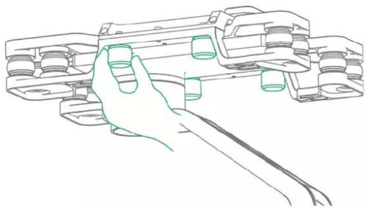
Loosen 4 mounting screws, as shown in Figure 3-9. Step 1
natural_image
Line drawing of a hand holding a mechanical component, no text or symbols presentFigure 3-9
Take down PTZ camera. Step 2
3.4.2 Install PTZ Camera
Insert the upper port on the vibration damper plate of the PTZ camera into Step 1 corresponding port at the bottom of the aircraft, as shown in Figure 3-10.

natural_image
Technical line drawing of a mechanical assembly with two views (top and side), no text or symbols present.Figure 3-10
____ Align 4 mounting screws with the hole positions at the bottom of the aircraft, and tighten Step 2 the screws.
3.5 Prepare Aircraft
3.5.1 Unfold Arm
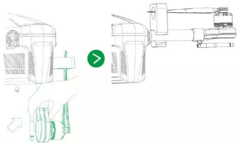
Unfold the arm to horizontal position. When you hear "clicking" sound, it means that the arm has been fixed, as shown in Figure 3-11.
! Caution
The subsequent steps can be implemented only when the arm is fixed. Please contact our company if the arm is loose.
natural_image
Technical line drawing of a mechanical device with a green arrow indicating direction (no text or symbols)Figure 3-11
3.5.2 Open Antenna

Tips
It is recommended to unfold the antenna to vertical position, in order to realize optimum communication effect.
Unfold the aircraft antenna, move it to vertical position and make it firmly stuck, as shown in Figure 3-12.

natural_image
Line drawing of a handheld device with a green circular indicator showing an arrow pointing to the handle (no text or symbols present)Figure 3-12
3.5.3 Remove Sheath
Remove sheath from the propellers, as shown in Figure 3-13.

natural_image
Technical line drawing of two identical mechanical components with a green circular indicator (no text or symbols)Figure 3-13
3.5.4 Open Propeller
After removing the sheath, unfold the propeller manually, as shown in Figure 3-14.

natural_image
Line drawing of a propeller with three blades and a base mount (no text or symbols)Figure 3-14
3.5.5 Install and Enable Aircraft Battery
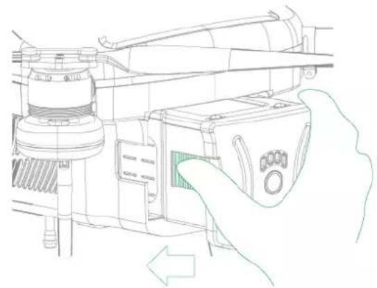
____ Pick up the battery and push it into the battery compartment horizontally, as shown in Step 1 Figure 3-15.
natural_image
Line drawing of a hand inserting a device into a machine (no text or symbols present)Figure 3-15
Step 2 When you hear "clicking" sound, the battery is put into the battery compartment completely, so the installation is completed, as shown in Figure 3-16.

natural_image
Technical line drawing of a mechanical assembly with no visible text or symbolsFigure 3-16
Short press it once and long press it for 3s. The battery is power-on, and the aircraft Step 3 enters self-inspection status.

Please don't move during self-inspection of the aircraft.
3.6 Prepare Remote Control
3.6.1 Install Micro SD Card
Remote control owns about 3G memory space. Please choose and install micro SD Card according to actual needs.

- The following chapter is optional for operation. It is for your reference when the user needs to install micro SD card.
- Micro SD card needs to be configured on your own.
• Micro SD card supports max. 16G.

Figure 3-17
Make the metal surface of micro SD card face downward and insert it into the micro SD card slot of the remote control side panel horizontally.
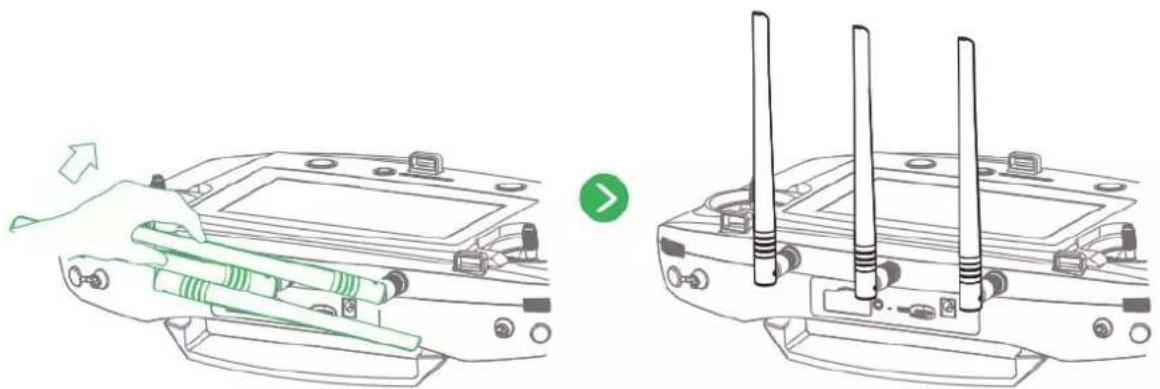
3.6.2 Open Antenna
Open the antenna of remote control to proper location, as shown in Figure 3-18.
natural_image
Technical line drawing of a device with two views showing internal components and a green arrow indicating motion (no text or symbols)Figure 3-18
3.6.3 Enable Remote Control Power

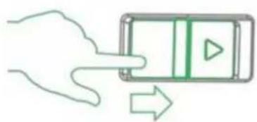
Please skip the chapter if the power is not turned off after checking remaining battery. Enable remote control power: move the power button of remote control to the arrow location, as shown in Figure 3-19.
natural_image
Illustration of a hand interacting with a smartphone displaying a play button (no text or symbols)
Figure 3-19
3.6.4 Confirm Remote Control Mode
It is mode 2 by default. Please set in "Settings > RC Settings > Joystick Mode" to switch mode, as shown in Figure 3-20.
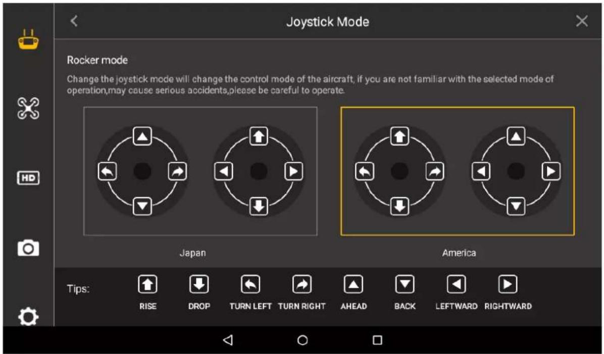
Figure 3-20
Please refer to "4.2.4 Manual Flight Control" for remote control mode and its corresponding relations.
3.6.5 Set Quick Operation
Click the upper right corner of main interface, set quick operation items of remote control interface, view dashboard, and set PTZ, image transfer, flight task, flight path and stop beep.
3.6.5.1 Dashboard
View parameters of remote control dashboard.
Click "Dashboard", and the system enters "Dashboard" interface, as shown in Figure 3-21.
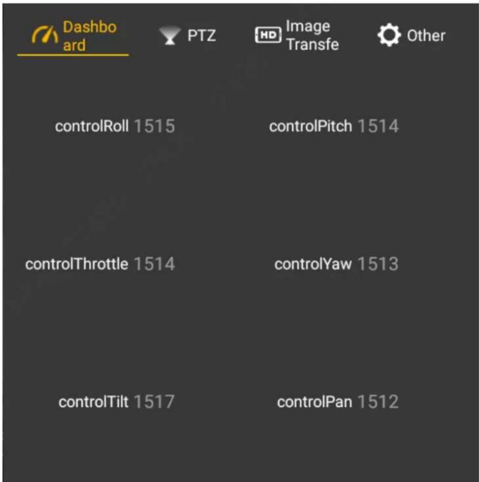
Figure 3-21
3.6.5.2 PTZ
Set the PTZ, such as PTZ position and throwing.
Step 1 Click "PTZ", and the system enters "PTZ" interface, as shown in Figure 3-22.

Figure 3-22
Set parameters according to actual needs. Please refer to Table 3-3 for details. Step 2
| Parameter | Note |
| PTZ Mode | View present mode of PTZ. |
| PTZ Position | Set PTZ position, including PTZ 90 degrees and PTZ center.PTZ 90 degrees: the camera is vertically downward.PTZ center: the camera lens faces the front. |
| Throwing | Set throwing, including throwing device A and throwing device B. |
Table 3-3

Click key A on the remote control, to carry out PTZ control.
3.6.5.3 Image Transfer
Set resolution ratio, frame rate and maximum bandwidth of preview image according to needs. Step 1 Select "Image Transfer", and the system enters "Image Transfer" interface, as shown in Figure 3-23.
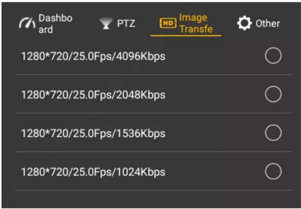
Figure 3-23
____ Select resolution ratio, frame rate and maximum bandwidth of preview image according Step 2 to actual needs.
3.6.5.4 Other
Set the flight task, flight path and stop beep here.
3.6.5.4.1 Fly Task
Set the flight task of remote control according to actual needs, including flight path and flight time.
Select "Other > Flight Task". Step 1 The system displays "Flight Task" interface, as shown in Figure 3-24.

Figure 3-24
Configure flight task according to actual needs. Step 2
- Append: click this icon to enter waypoint setting interface, set waypoint flight task according to actual needs and save it.
- Download: click this icon to download present saved flight path automatically. Modify waypoint according to actual needs and save the task at remote control.
- Select: click this icon to select one task or multiple tasks, and delete the task.
3.6.5.4.2 Flight Data
Save and delete the flight path data of the aircraft.
Select "Other > Flight Data". Step 1
The system displays "Flight Data" interface, as shown in Figure 3-25.

Select the flight path which shall be deleted and saved according to actual needs, as shown in Figure 3-26.
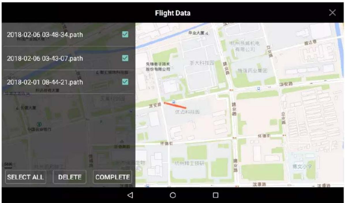
Click "Complete" to complete flight data setting. Step 3

Tips
Click "Select All" to operate all flight data together.
3.7 Enable Aircraft Power

Caution
After power on, when the remote control doesn't require other operations, please always keep the aircraft horizontal and static; otherwise, it may result in initialization failure.
Insert intelligent battery of the aircraft, so the aircraft is power-on and indicator light indicates present battery electricity, as shown in Figure 3-27.

natural_image
Hand pressing a circular diagram with red and green segments (no text or symbols)Figure 3-27
3.8 Check and Debugging
Warning
The subsequent steps can be implemented only after checking and debugging all the items listed in the chapter below. Besides, the remote control prompts that each state is normal and the aircraft indicator light flashes green.
Tips
It is recommended to set the display image of remote control as video preview mode before taking off.
Check operation condition. Please debug each component to make it operate normally when both remote control prompts abnormality.
It is going to list common calibration items, abnormalities and solutions in the following chapter.
3.8.1 Remote Control Calibration
Caution
If it isn't turned to maximum value end, it may not respond to operation, operation is not smooth, and the aircraft may even explode after calibration.
Note
- After calibration, view "3.6.5.1 Dashboard", and turn corresponding buttons to confirm if calibration is successful. After successful calibration, each parameter is about 1514. Turning the endpoint, maximum value is 19XX while minimum value is 10XX.
• The remote control can be normally used about 30s after calibration.
Step 1 Select "Settings > Remote Control Settings> Joystick Calibration".
The system displays "Joystick Calibration" interface, as shown in Figure 3-28.

Figure 3-28
Move both the left and right joysticks back to the middle. Step 2
Click "Start Calibration". Step 3
____ Turn two joysticks and turn to the maximum value end of each direction for several Step 4 times.
____ Slide the rolling wheels on both sides, slide to the maximum value end of two directions Step 5 for several times.
Step 6 Click "Complete Calibration" after turning the rolling wheels and joysticks.
3.8.2 Accelerometer Calibration

Caution
Pay attention to levelness and perpendicularity during calibration. Non-standard posture during calibration will lead to abnormal flight and even explosion.
Select "Settings > General > Other > Accelerometer Calibration" to enter "Accelerometer Calibration" interface, as shown in Figure 3-29.

Figure 3-29
Place the aircraft on a flat surface, and click "Start Calibration".
- The remote control will prompt "Calibration Success" if it is successfully calibrated.
- The remote control will prompt "Calibration Failure" if it fails to calibrate. Click "Retry" till it is successfully calibrated.
3.8.3 Initialization Failure
Abnormity Prompt
Remote control prompts "Initialization Failure".
Possible Reasons
After power on and before taking off, it may result in initialization failure if you move the aircraft.
Solutions
Power on the aircraft again after the power is cut off, and keep the aircraft horizontal and static during initialization. Please contact our company if initialization fails for several times.
3.8.4 Geomagnetic Abnormity
Abnormity Prompt
- Aircraft indicator flashes ● ● ●
- Remote control prompts "Geomagnetic Abnormity".
Possible Reasons
- The use position has changed a lot, which means the geographical location is quite far away from the last geographical location where the aircraft is used, causing big change to geomagnetic field.
- There is another intensive magnetic field or abrupt change in the environment, affecting geomagnetic field.
Solutions
Step 1 Select "Settings > General > Other > Geomagnetic Calibration" on the remote control. The system displays "Geomagnetic Calibration" interface, as shown in Figure 3-30.
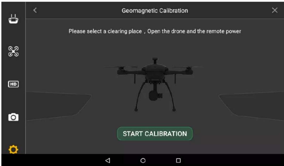
Figure 3-30
____ Click "Start Calibration". Step 2
____ Keep the aircraft horizontal and rotate it for 360° horizontally, as shown in Figure 3-31. Step 3

natural_image
Diagram of a quadcopter drone with four propellers and a green circular motion indicator (no text or symbols)Figure 3-31
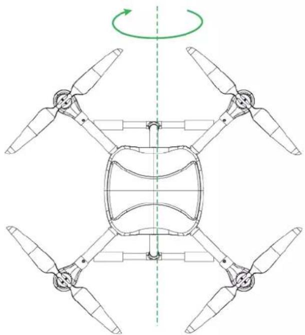
____ Keep the aircraft vertical and rotate it for 360^ vertically, as shown in Figure 3-32. Step 4
natural_image
Top-down technical diagram of a four-blade propeller assembly with a green rotation arrow indicating rotational motion (no text or symbols)Figure 3-32
- It will prompt geomagnetic calibration success if it is successfully calibrated.
- It will prompt geomagnetic calibration failure if it fails to calibrate. Repeat Step 2, 3 and 4 to calibrate again.
3.8.5 GPS Satellites Insufficiency
Abnormity Prompt
- Displayed number of satellites of remote control is less than 6.
- GPS HDOP: 📄 at the top status bar of remote control is less than 1 bar or there is no signal.
Possible Reasons
- The flying environment is not wide open enough, which is severely blocked.
- There is some other interference around the surroundings.
Solutions
Move the aircraft to a wider area and wait for 30s.

Note
This chapter will elaborate the complete flow of formal takeoff and landing of the aircraft.

Danger
Please stay away from the rotating propellers or motor, to avoid personal injury.

Warning
For your personal and property safety, please make sure to check the following items carefully before enabling flight.
- Flight preparations listed in Chapter 3 are all completed.
- All the components have been correctly and stably installed.
- Make sure that each spare part is in good condition. Please do not fly the aircraft if some parts are aged or damaged.
- Flight environment meets the requirements listed in important safeguards and warnings.

Caution
Please do not block the ventilation near heat dissipation hole when the motor is operating.
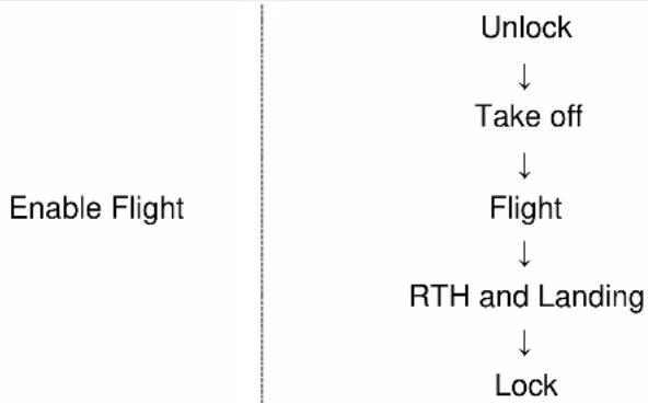
flowchart
graph TD
    A["Unlock"] --> B["Take off"]
    B --> C["Flight"]
    C --> D["RTH and Landing"]
    D --> E["Lock"]
Figure 4-1
4.1 Flight Mode
Control flight mode via driving lever during flight phase, as shown in Figure 4-2.

Figure 4-2
Three-level driving lever:
- Upper level: Intelligent flight mode. The aircraft will fly automatically according to the pre-set flight route.
- Medium level: It is the fixed height flight mode in manual flight mode. The aircraft will maintain the current flight height when the throttle joystick is in the middle.
- Lower level: Fixed point flight mode in manual flight mode. The aircraft will maintain the current location when all sticks are located in the middle.
4.2 Manual Flight Mode
4.2.1 Introduction to Manual Flight Flow
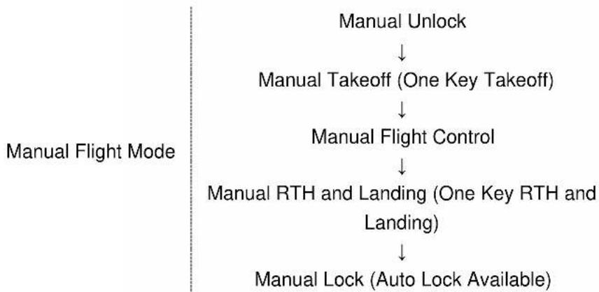
flowchart
graph TD
    A["Manual Unlock"] --> B["Manual Takeoff (One Key Takeoff)"]
    B --> C["Manual Flight Control"]
    C --> D["Manual RTH and Landing (One Key RTH and Landing)"]
    D --> E["Manual Lock (Auto Lock Available)"]
Figure 4-3
4.2.2 Unlock Flight Control
Move the left joystick to lower left, meanwhile move the right joystick to lower right (or move the left joystick to lower right, meanwhile move the right joystick to lower left), and keep the status for 2s. At this moment, the propellers are unlocked and start to rotate. Move all the sticks back to middle, as shown in Figure 4-4.
Mode 1

Figure 4-4
! Caution
- If there is obvious difference about rotating speed of the propellers, move the left joystick to lower left and meanwhile move the right joystick to lower right (or move the left joystick to lower right, and meanwhile move the right joystick to lower left), and then keep the status till the propellers stop rotating. Turn off the aircraft and contact our company.
- The aircraft will be automatically locked if it stays on the ground and doesn't take off within 10s after it is unlocked.
4.2.3 Manual Takeoff
Slightly push the throttle to mid-point or higher, as shown in Figure 4-5.

Figure 4-5
4.2.4 Manual Flight Control
Set remote control mode and control flight direction of the aircraft.

flowchart
graph TD
    A["Course right turn"] --> B["Accelerator up, ascend"]
    B --> C["Horizontal, backward"]
    C --> D["Move left"]
    D --> E["Horizontal, forward"]
    E --> F["Move right"]
    F --> G["Accelerator down, descend"]
    G --> H["Course left turn"]
    style A fill:#f9f,stroke:#333
    style B fill:#ccf,stroke:#333
    style C fill:#cfc,stroke:#333
    style D fill:#fcc,stroke:#333
    style E fill:#cff,stroke:#333
    style F fill:#ffc,stroke:#333
    style G fill:#cfc,stroke:#333
    style H fill:#fcc,stroke:#333
Figure 4-6
The joystick presets two remote control modes.
It is mode 2 by default. Please modify in "Settings > Remote Control Settings > Joystick Mode" to switch to mode 1.
- Mode 1:
-
Vertical direction of left joystick is pitching joystick, which controls the aircraft to go forward and backward horizontally.
◇ Horizontal direction of left joystick is course joystick, which controls the aircraft to make left and right turn horizontally. -
Vertical direction of right joystick is throttle joystick, which controls the aircraft to ascend and descend.
Horizontal direction of right joystick is rolling joystick, which controls the aircraft to move left and right horizontally.

flowchart
graph TD
    A["Left Turn"] --> B["Forward"]
    B --> C["Right Turn"]
    C --> D["Back"]
    E["Move Left"] --> F["Ascend"]
    G["Move Right"] --> H["Ascend"]
    I["Descend"] --> J["Ascend"]
Figure 4-7
- Mode 2:
- Moving the left joystick up and down (throttle joystick) to control aircraft's ascending and descending.
- Moving the left joystick left and right (course joystick) to control aircraft's left and right turn horizontally.
- Moving the right joystick up and down (pitching joystick) to control aircraft's forward and backward movement horizontally.
- Moving the right joystick left and right (rolling joystick) to control aircraft's left and right movement horizontally.
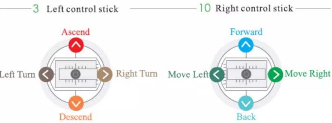
Figure 4-8
4.2.5 Manual RTH and Landing
- Manual RTH: Control the aircraft to hover over a proper landing point.
- Manual landing: Reduce the throttle to make the aircraft land slowly.

Figure 4-9
4.2.6 Manual Locking
Move the left joystick to lower left and move the right joystick to lower right at the same time (or move the left joystick to lower right and move the right joystick to lower left at the same time).
Mode 1

Mode 2
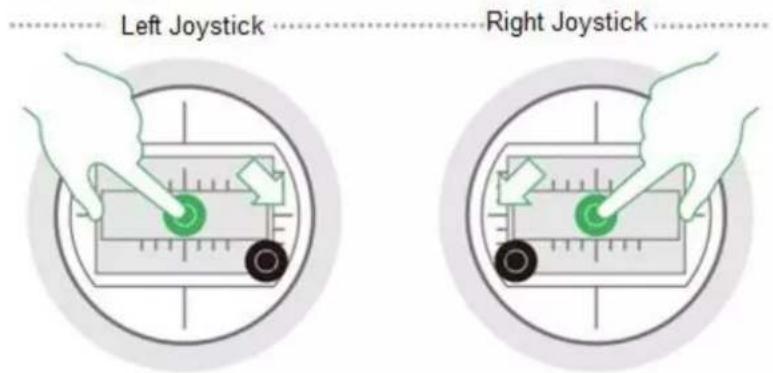
Figure 4-10
4.3 Intelligent Mode
4.3.1 Intelligent Flight Mode
Intelligent flight mode includes waypoints and circle around point of interest.
- Waypoints flight: Set waypoint flight mission according to requirements. Move the flight mode joystick at right rear of remote control to intelligent mode after the aircraft takes off, select proper flight mission and click "Start Mission".
- Circle (around point of interest) flight: Set circle flight mission according to requirements. Move the flight mode joystick at right rear of remote control to intelligent mode after the aircraft takes off, select proper flight mission and click "Start Mission".

Note
- When the flight mode joystick of remote control is moved to any mode (point, elevation or intelligent mode), you can set waypoint flight or circle flight and save flight mission.
- The aircraft is allowed to implement flight mission only when the flight mode joystick of remote control is moved to the intelligent mode (Mode F).
- It can realize waypoint flight or point of interest circle flight only after the aircraft takes off, and it can't be realized on the ground.
Click the button on the main interface of the remote control, and enter the interface of intelligent flight mode, as shown in Figure 4-11.
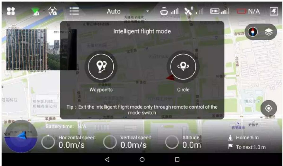
Figure 4-11
4.3.1.1 Waypoints
Select "Waypoints". Step 1
The system displays "Waypoints" interface, as shown in Figure 4-12.

Note
Check total route length, estimated flight time and set "Cycle Flight" at the bottom of the interface.
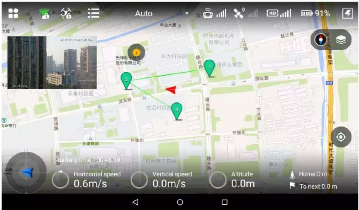
____ Click the map and the position can be set as a waypoint; several waypoints can be Step 2 connected together and form a route.

Note
Check total route length, estimated flight time and set "Cycle Flight" at the bottom of the interface.
____ Click a waypoint and it will become red. Waypoint setting interface will display on the Step 3 right of the interface, as shown in Figure 4-13.

Figure 4-13
Set waypoint parameters. Please refer to Table 4-1 for more details. Step 4
| Parameter | Note |
| Altitude | Set flight altitude of waypoint. |
| Speed | Set flight speed of waypoint |
| Head orientation | Set head orientation of waypoint according to requirement during flight. |
| Residence time | Set hovering time after the aircraft reaches a waypoint. |
| Latitude and longitude | Automatically acquire latitude and longitude of the waypoint when adding the waypoint.Manually set waypoint latitude and longitude. Waypoint position will skip to manual setting point after setting is done. |
| Waypoint action | No action: it is not to set waypoint action.Shutter: it will take photos after the aircraft arrives at the waypoint. |
| Action cycle | Action cycle setting is invalid when the waypoint action selects “No Action”.When waypoint action selects “Shutter”, input time. The aircraft arrives at the waypoint and it will take a photo after a period of time.[KX35]NoteAction cycle shall be less than or equal to residence time. |
Table 4-1
Click "Save" to make configuration valid. Step 5

Note
Click to set waypoint parameters in batches. Meanwhile, it can modify or delete several waypoints.
Step 6 Click ★ to input mission name, click "Save" and you can check saved flight missions in the list.

Click to enter flight mission interface. There are three operations:
- Add mission: Click the icon to enter waypoint setting interface, set waypoint flight mission and save it according to actual requirements.
- Download mission: Click the icon to automatically download the currently saved flight route. You can modify the waypoint according to actual requirement and save it into the remote control.
- Select mission: Click the icon, select one or more missions on the interface, and delete the mission(s).
4.3.1.2 Circle
Select "Circle". Step 1
The system displays "Circle" interface, as shown in Figure 4-14.
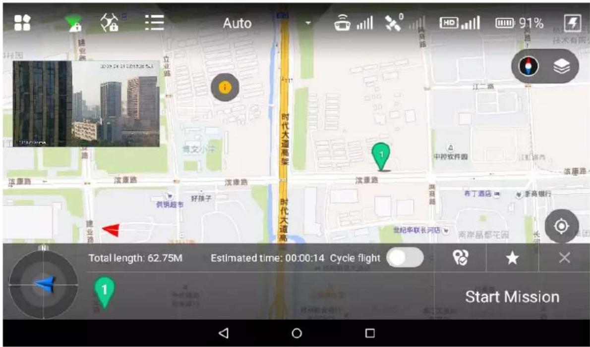
____ Click the map and the position can be set as interest point. Step 2
____ Click the interest point, and the point icon will become red. Settings interface of interest Step 3 point will be displayed on the right of main interface, as shown in Figure 4-15.

Figure 4-15
Set the parameters of interest point. Please refer to Table 4-2 for more details. Step 4
| Parameter | Note |
| Altitude | Set flight altitude of interest point. |
| Speed | Set flight speed of interest point. |
| Cycle radius | Set flight radius of aircraft flying around interest point. |
| Cycle mode | Select the flight direction of aircraft flying around interest point, clockwise optional. |
Table 4-2
Click "Save" to make configuration valid. Step 5

Note
Set one interest point only for each flight mission.
Step 6 Click to input mission name, click "Save" to save flight mission.
4.3.2 Intelligent Locking Mode
Click will pop out a dialog box. Select locking mode of the aircraft. Step 1

Figure 4-16
There are two types of intelligent locking modes, namely course lock and return lock.
- Course lock: Click it to lock the present head direction as its forward direction. During the following flight process, the aircraft course has nothing to do with the head direction; the aircraft will always move forward according to the locked head direction.
- Return lock: Click it and the aircraft course has nothing to do with the head direction. Always take the straight line direction far away from HOME point as forward direction and the straight line direction close to HOME point as backward direction.
If both modes are canceled: the aircraft head direction is forward direction.
Step 2 Click "Return Lock" and the icon becomes yellow, and it will prompt "Return Lock Enabled".
Click "Course Lock" and the icon becomes yellow, and it will prompt "Course Lock Enabled".
4.3.3 Intelligent Operation
4.3.3.1 Auto Takeoff
In fixed point mode, first unlock flight control, and then short press the takeoff and landing button on the front panel of the remote control. The aircraft will take off automatically and begin flight according to the pre-set route.
natural_image
Illustration of a hand interacting with a touchscreen icon and a circular button (no text or symbols)Figure 4-17
4.3.3.2 Auto RTH and Landing

Note
The landing under the condition of low battery or in the uncontrollable situation has been introduced in other chapters; this chapter will only introduce the landing modes in other situations.
Short press RTH button on the front panel of the remote control, and the aircraft will return Home.

natural_image
Illustration of a hand interacting with a green circular button and two gray circular icons (no text or symbols)Figure 4-18
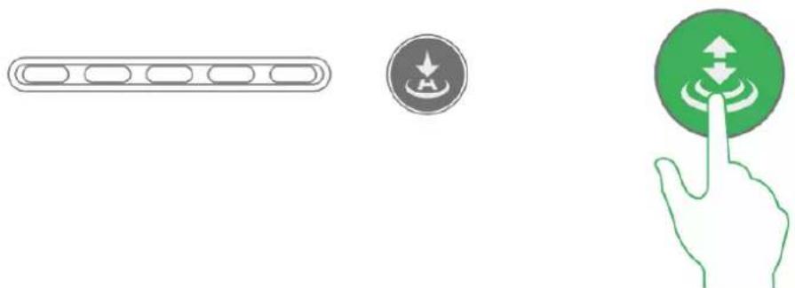
4.3.3.3 One-key Landing
Under the present condition, the aircraft needs to land vertically.
Short press the takeoff and landing button on the front panel of the remote control, and the aircraft will land at the current position automatically.

natural_image
Illustration of a finger pressing a green circular button with arrows, alongside a gray rectangular button and a starburst icon (no text or symbols)Figure 4-19

Note
One-key landing doesn't return Home, but the aircraft will land at the current position immediately.
4.4 Intelligent Protection Mechanism
4.4.1 Low Battery
There are totally three prompts of aircraft low battery for the remote control, and each prompt is more serious than the previous one.
- Level-one low battery, remote control prompts message: "Low Voltage Alarm", along with alarm sound.
- Level-two low battery, remote control prompts message: "Serious low voltage home", along with alarm sound. First ascend to 120m, and return to HOME point.
- Level-three low battery, remote control prompts message: "Serious low voltage landing", along with alarm sound. Meanwhile, the aircraft triggers landing mode.
4.4.2 Out of Control
- The aircraft may run into the following out of control situations:
◇ The aircraft or remote control antenna is damaged, and it fails to receive and send signals.
- Intensive magnetic field arises in ambient environment, which interferes with the aircraft and remote control.
- Solutions:
Out of control auto return: ascend the aircraft to 120m first and then return to HOME point.
4.5 Remote Control Setting
4.5.1 Remote Button User-defined
Set the function of "A" button on the remote control, including "One button to return to center" and "One button 90°".
Select "Settings > Flight Control Settings > Remote Control Settings > Remote Button User-defined". The system displays "Remote Button User-defined" interface, as shown in Figure 4-20.
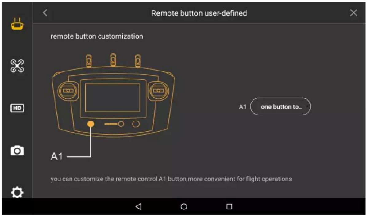
Figure 4-20
4.5.2 Flight Control Settings
4.5.2.1 Fence Settings
Select "Settings > Flight Control Settings > Fence Settings". The system displays "Fence Settings" interface, as shown in Figure 4-21.

Figure 4-21
Draw electronic fence area.
Select "Settings > Flight Control Settings > Fence Settings > Fence Type", as shown in Figure 4-22.
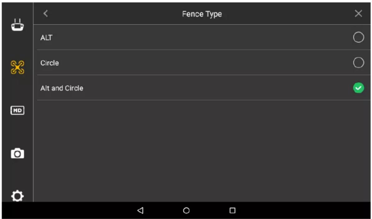
Figure 4-22
- ALT (Limited altitude): limit the max. flight altitude of the aircraft, but there is no limit in horizontal direction of the aircraft.
- Circle: Take HOME point as circle center and the set value as radius. The aircraft is restricted to fly within the circle, and there is no limit to the altitude.
- ALT and Circle: Take HOME point as circle center and set value as radius. The set height is considered as max. flight altitude; the aircraft is restricted to fly within the cylindrical area.
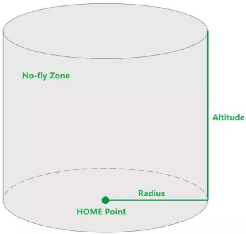
Figure 4-23
4.5.2.1.2 Fence Action
Select "Settings > Flight Control Settings > Fence Settings > Fence Action", as shown in Figure 4-24.
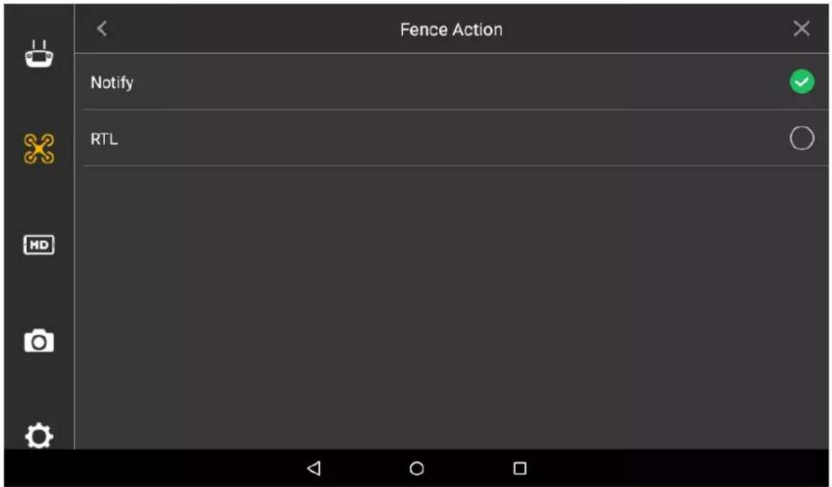
Figure 4-24
- Notify: The aircraft hovers in the air when electronic fence is triggered. Preview interface of remote control gives a prompt, along with buzzing.
- RTL: When electronic fence is triggered, preview interface of remote control gives a prompt, along with buzzing. Meanwhile, the aircraft returns automatically.
4.5.2.1.3 Other Settings
Select "Settings > Flight Control Settings > Fence Settings".
- Set radius and altitude.
- Set trigger distance.
For example, when the fence type is set as radius + altitude, the radius is set as A meters and altitude is set as B meters, and if the trigger distance is set as C meters, then it will trigger RTH or landing when the aircraft is (A-C) meters away from the HOME point horizontally or flight altitude exceeds (B-C) meters; the aircraft will implement the action of RTH or landing.
4.5.2.2 Enable Electronic Fence
Enable electronic fence after setting fence area.
Select "Settings > Flight Control Settings", enable electronic fence on the right of the "Fence Enable".

Figure 4-25
4.5.3 Preview Settings
Set resolution, frame rate and max. bandwidth of preview image according to requirements. Step 1 Select “Settings > Flight Control Settings > Preview Settings” and enter the preview setting interface, as shown in Figure 4-26.
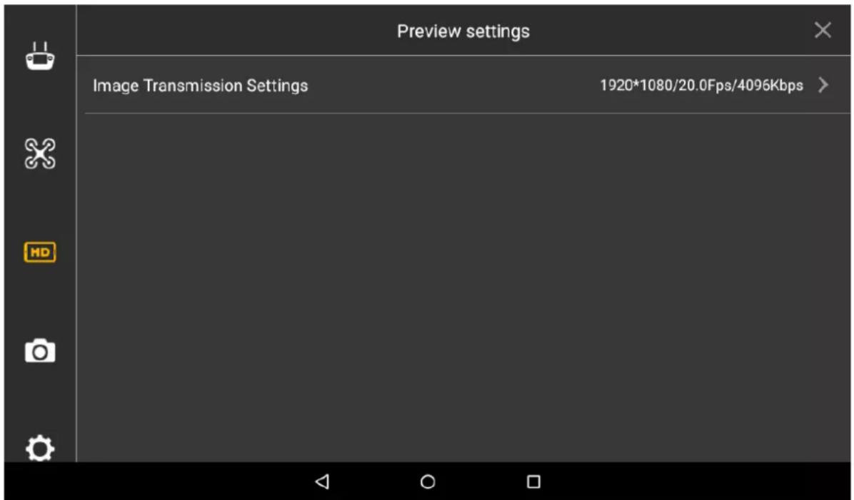
Figure 4-26
Step 2 Select "Settings > Flight Control Settings > Preview Settings > Image Transmission Settings".
The system displays "Image Transmission Settings" interface, as shown in Figure 4-27.
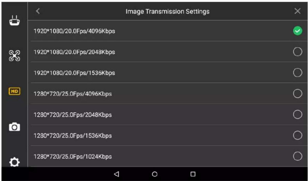
Figure 4-27
Select one option. Step 3
Icon at the end of selected line becomes green and checked, which makes it valid immediately.
4.5.4 Camera Settings
4.5.4.1 Photo Settings
Set resolution, frame rate and max. bandwidth of photos taken by PTZ camera according to requirements.
Select "Settings > Camera Settings > Photo Settings". Step 1
The system displays "Photo Settings" interface, as shown in Figure 4-28.
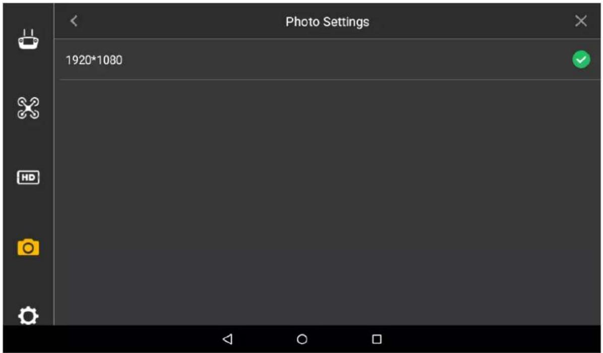
Figure 4-28
Select one line. Step 2
Icon at the end of selected line becomes green and checked, which makes it valid immediately.
4.5.4.2 Video Settings
Select to enable "Camera Auto-take Video When Unlock" or not; select the resolution, frame rate, stream and coding format of PTZ camera.

Note
Please ensure that the aircraft is unlocked during video setting. Video setting can be realized only under unlocked status.
Select "Settings > Camera Settings > Video Settings". Step 1
The system displays "Video Settings" interface, as shown in Figure 4-29.

Figure 4-29
Step 2 Select the switch behind "Camera Auto-take Video When Unlock". When the switch turns green and ticked, it means that the function is enabled.
Step 3 Select "Resolution/FPS/KBps", click a line, and icon at the end of selected parameter line becomes green and checked, which makes it valid immediately.
Select "Stream Format", as shown in Figure 4-30. Step 4
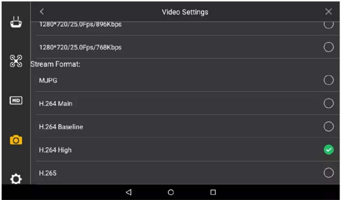
Figure 4-30
____ Click a line, and icon at the end of selected parameter line becomes green and Step 5 checked, which makes it valid immediately.
- MJPG: In this mode, video image needs relatively high stream value to guarantee definition. To obtain a good effect, it is suggested to use maximum stream value among reference stream value.
• H.264 Main: Main Profile mode.
• H.264 Baseline: Baseline Profile mode.
• H.264 High: High Profile mode.
• H.265: Main Profile mode.
4.5.4.3 Image Settings
Set the brightness, contrast, saturation, sharpness and gamma value of the preview image of PTZ camera.
Step 1 Select "Settings > Camera Settings > Advanced Settings > Image Settings".
The system displays "Image Settings" interface, as shown in Figure 4-31.

Figure 4-31
Set the parameter items on the right of the interface. Step 2
- Brightness: Adjust the overall brightness of the image; adjust the value when the overall brightness of image is too bright or too dark.
- Contrast: Adjust the image contrast. Adjust the value when overall brightness is proper but the image contrast is not enough.
- Saturation: Adjust the bright degree of the color, which will not affect the overall brightness of the image.
- Sharpness: Adjust the image resolution and sharpness degree of image edge.
- Gamma: Optimize brightness and contrast, and adjust slight brightness and darkness layer of the image.
Set parameter value by sliding, and it is valid immediately. Step 3
4.5.5 General Settings
Realize firmware update and other settings, including brightness, date and time, network setting, language and Micro SD card setting.
4.5.5.1 Other Settings
4.5.5.1.1 Network Settings
Network access of remote control includes Wi-Fi, mobile hotspot and 4G.
Step 1 Select "Settings > General Settings > Other Settings > Network Settings".
The system displays "Network Settings" interface, as shown in Figure 4-32.
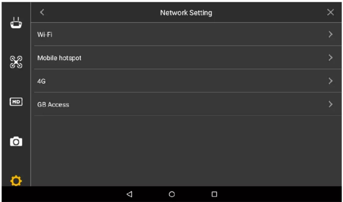
Figure 4-32
Select "Network Setting". Step 2
- Wi-Fi: Enable "WLAN", connect the remote control with wireless network, and thus transmit data through wireless network.
- Mobile hotspot: Enable "Mobile WLAN Hotspot", so the user's mobile phone or other devices are connected with the network through mobile hotspot.
- 4G: Select "Connect", enable 4G mode of the remote control and connect the remote control with 4G network.
4.5.5.1.2 Micro SD Settings
View total space of Micro SD card and the space occupied by every part.
Select "Settings > General Settings > Other Settings > Micro SD Card Settings > Storage Settings". The system displays "Storage Settings" interface, as shown in Figure 4-33.
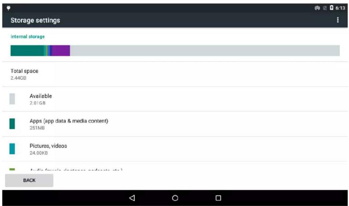
Figure 4-33
4.5.5.1.3 Brightness
Set the overall display brightness of the remote control touch screen.
Step 1 Select "Settings > General Settings > Other Settings > Brightness". The system displays "Brightness" interface, as shown in Figure 4-34.
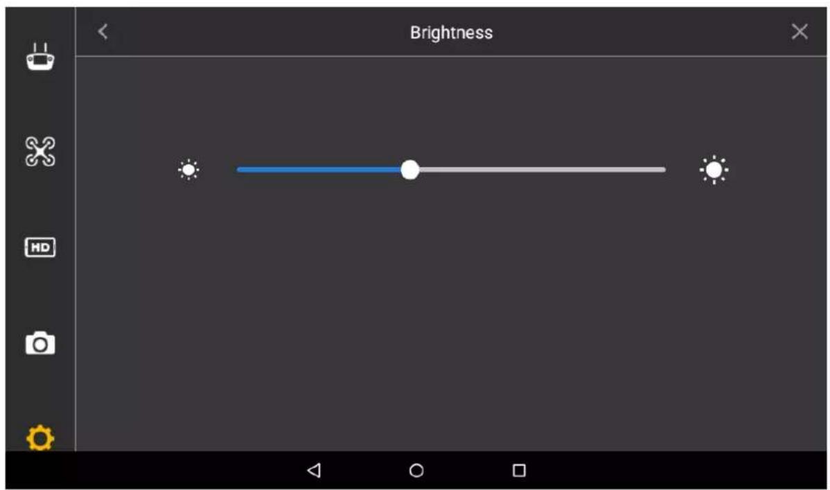
Figure 4-34
Drag the adjustment bar to set overall brightness of remote control. Step 2 It becomes darker when the adjustment bar moves left, and becomes brighter when it moves right.
4.5.5.1.4 Date and time
Set the date, time and time zone displayed on the remote control.
Step 1 Select "Settings > General Settings > Other Settings > Date and Time". The system displays "Date and Time" interface, as shown in Figure 4-35.

Figure 4-35
Set parameters according to actual needs. Please refer to Table 4-3 for more details. Step 2
| Parameter | Note |
| Date | Click it to set date of remote control. |
| Time | Click it to set time of remote control. |
| Time Zone | Click it to set present time zone of remote control. |
Table 4-3
4.5.5.1.5 Language
Set the language displayed on the remote control.
Step 1 Select "Settings > General Settings > Other Settings > Language". The system displays "Language" interface, as shown in Figure 4-36.

Figure 4-36
According to actual needs, select English or Chinese. Step 2
4.5.5.2 About
View hardware device model and version info.
Select "Settings > General Settings > About" to enter "About" interface, as shown in Figure 4-37.

Figure 4-37

Note
• This chapter elaborates the operation steps after aircraft landing.
- Please operate according to the following flows to make sure normal application for the next time. Some of the operations are not indispensable. Please select according to the actual situation.
End Flight

flowchart
graph TD
    A["Turn off power"] --> B["Fold aircraft"]
    B --> C["Dismantle image transmission antenna"]
    C --> D["Take out other components"]
Figure 5-1
5.1 Turn off Power

Caution
It has to turn off the aircraft power first, and then turn off the power of remote control.
Short press the power switch of aircraft battery once, and long press it for 3s, so as to Step 1 turn off aircraft power.
____ Press the snap joints at both ends of the battery, and separate the battery from battery Step 2 compartment.
____ Keep the battery horizontal and take it out, as shown in Figure 5-2. Step 3
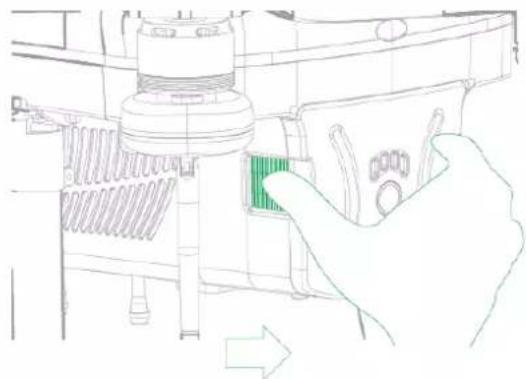
natural_image
Line drawing of a hand operating a device with a green control panel (no text or symbols)Figure 5-2
Move the power switch on the rear panel of the remote control to the other side. It Step 4 means that remote control power has been turned off when the indicator light of remote control front panel is off.
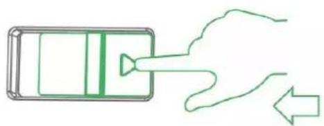
natural_image
Simple line drawing of a hand pouring liquid into a rectangular container with a triangular inlet (no text or symbols)
Closed
Figure 5-3
5.2 Dismantle Air-borne Device
Loosen 4 mounting screws, as shown in Figure 5-4. Step 1
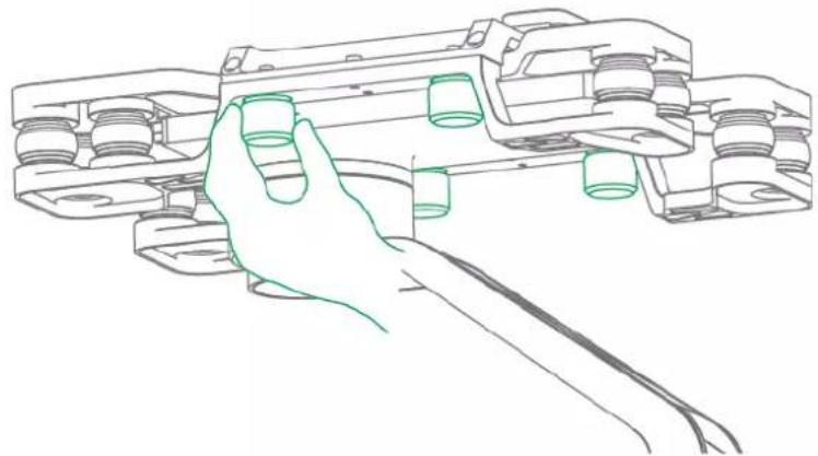
natural_image
Line drawing of a hand holding a mechanical component (no text or symbols)Figure 5-4
Dismantle the PTZ camera. Step 2
5.3 Fold Aircraft
Fold propeller blades, and and fix them onto the arm with sheath, as shown in Figure Step 1 5-5.
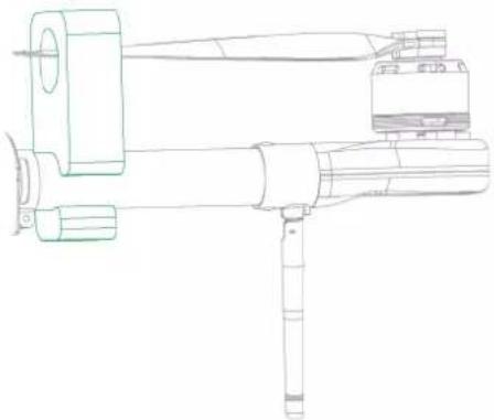
natural_image
Technical line drawing of a mechanical device with no visible text or symbolsFigure 5-5
____ Restore the antenna and keep it close to the arm, as shown in Figure 5-6. Step 2

Figure 5-6
____ Hold the arm with hand, move the arm wrench, fold the arm downwards and keep it Step 3 close to landing gear, as shown in Figure 5-7.

natural_image
Line drawing of hands operating a mechanical device with a tool (no text or symbols)
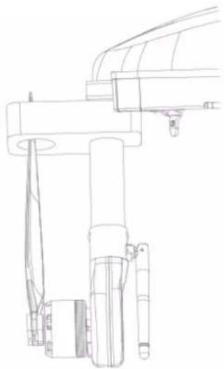
natural_image
Technical line drawing of a mechanical assembly with no visible text or symbolsFigure 5-7
5.4 Copy Video of Camera Micro SD Card

Figure 5-8
____ Open micro SD card plug with hands. Step 1
____ Slightly press micro SD card and it will pop out. Pull out the micro SD card. Step 2
Insert the micro SD card into the card reader, and connect the card reader to computer. Step 3
Copy the micro SD card video into the computer via card reader and save it.
5.5 Remove Other Components
- Remove SIM card: open silicone cover of side panel, pull out SIM card and close the silicone cover.
- Fold remote control antenna: Fold the antenna and make it close to the front panel of remote control.
This chapter elaborates upgrade methods of the device.
6.1 Firmware Update

Note
The aircraft and remote control have to be enabled and connected during firmware update, in order to pair them successfully.

Warning
Don't upgrade the firmware during flight!
Update flight control, transmitting and receiving firmware of the aircraft, as well as transmitting and receiving firmware of the remote control.
Insert the micro SD card with firmware update package into the micro SD card slot of Step 1 the remote control.
Select "Remote Control > Settings > General Settings". Step 2 The system displays "Firmware Update" interface, as shown in Figure 6-1.
Firmware Update
UPDATE NOW
Figure 6-1
Select "Update Now". Step 3
The system starts to update the firmware.

Note
If micro SD card isn't inserted, it will display the latest version on the right of each firmware.
6.2 Remote Control Update
6.2.1 APP Update
Insert the micro SD card with APP update package into the micro SD card slot of the Step 1 remote control.
Select "Settings > General Settings". Step 2
It will display the current APP version number or update software on the right of "APP Update", as shown in Figure 6-2.
APP Update
1.2.14
Figure 6-2
- It doesn't need to update when it displays the version number, and it means that the current APP is the latest version.
- Update is available when it displays "Update Now".
Select "Update Now". Step 3
Update automatically and display update progress.
After successful update, version number in the above figure will be the same as update software.
6.2.2 Download and Update Offline Map of Remote Control
Insert 4G-SIM card or connect Wi-Fi, so the remote control accesses the network. Step 1 Step 2 Select "Settings > General Settings > Other Settings > Offline Map".
The system displays the interface of "Offline Map", as shown in Figure 6-3.
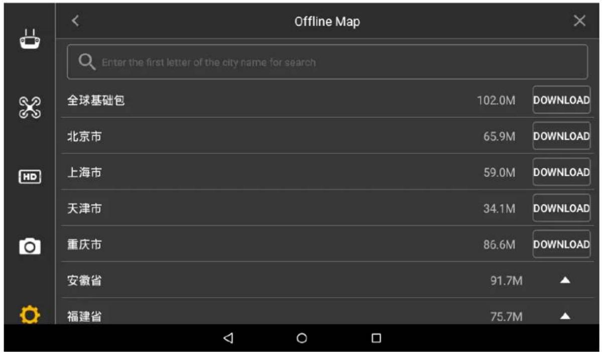
Figure 6-3
Step 3 Select the city which needs to be updated, and then click "Download" button in the right.
The map takes effect immediately, without need for other operations. Step 4
| Parameter Item | Parameter Value | |
| Model | Navigator X650 | |
| System Environment Adaptability | Operating temperature | -20°C~60°C |
| Operating humidity | Operating humidity is 95%, non-condensation. | |
| Aircraft | Wheel base | 650mm |
| Aircraft type | 4 rotor wings | |
| Mechanical features of arm | Foldable | |
| Rack weight (except battery and load, only power system) | 2530g | |
| Battery weight | 1700g | |
| Satellite positioning module | GPS | |
| Max. flight altitude | No less than 5000m | |
| Battery | 6S LiPo 12000mAh intelligent battery | |
| Max hovering time | 30min | |
| Power System | Propeller wing material | Carbon fiber |
| Propeller wing dimension | 16 inch | |
| Mechanical features of propeller wing | Foldable | |
| Flight Control | Hovering accuracy (relative accuracy) | Horizontal: ±0.2mVertical: ±0.5m |
| Wind resistance capacity | 6 wind scale | |
| Max. attitude angle velocity | Course: 150°/sPitch: 250°/s | |
| Max. attitude angle | 35° | |
| Cruising speed | 10m/s | |
| Built-in function | Fixed elevation, fixed point, autonomous cruise and several other flight modesAuto takeoff and landingLow voltage protectionLED and remote control APP promptAuto RTHPreset no-fly zoneElectronic fence | |
| PTZ | Weight (including load) | 880g |
| Angle control accuracy | ±0.01° | |
| Max. controllable rotation speed | Course: ±130°/sPitch: ±130°/s | |
| Controllable rotation range | Course:±173°Pitch: -90° to +45° | |
| Installation mechanical feature | Quick mount and demount | |
| Built-in function | Two working modes:◇ Course follow mode (relative position of aircraft and PTZ doesn't change)◇ Course lock mode (the angle between PTZ and the ground doesn't change)Built-in independent IMU moduleX650 exclusive servo drive moduleEthernet video transmission and camera PTZ control | |
| Visible Light Camera (2 MP, 30X optical zoom) | Sensor | 1/2.8" 2MP CMOS |
| Max resolution | 1920 (H) *1080 (V) | |
| View angle | 67.8° ~2.77° | |
| WDR | Support | |
| Video compression standard | H.264 Base line Profile | |
| Frame rate | 20fps@1080p, 25/30fps@720p | |
| Iris | F1.6~F4.4 | |
| Focal length | 4.5mm~135mm (30x optical zoom) | |
| Digital NR | 3D&2D | |
| SNR | ≥55dB (AGC Off, Weight ON) | |
| Min illuminance | Color: 0.005Lux@F1.6Black and white: 0.0005Lux@F1.6 | |
| Backlight compensation mode | BLC/HLC | |
| Day/night switch | Auto/Manual | |
| WB | Auto/Manual/Tracking/Outdoors/Indoors/Outdoors Auto/Sodium Lamp Auto/Sodium Lamp | |
| Electronic shutter | 1/1s~1/30000s | |
| Storage | 128GB Micro SD card | |
| Integrated remote control | Features | Integrated design of remote control display |
| Remote control distance | ≥5km | |
| Remote control dimension | 350mm×228mm×85mm | |
| Battery | 7800 mAh | |
| Output port | micro USB, headset port | |
| Operating screen and system | Screen size: 7" (Multi-point capacitance)Resolution: 1024*600OS: Android 5.1 | |
| Network | Wi-Fi IEEE802.11 b/g/n | |
| Image transmission distance | Max. 10km | |
| Data transmission distance | Max. 10km | |
| Storage | 128GB Micro SD card | |
| Software function | Parameter settingAuto planning of tour missionPattern template import/exportAuto takeoff/landingReal-time switch of video and mapSmart flight mode:Course lockRTH lockCircle around point of interestWaypoint flightMission record2D map | |
Appendix Table 1-1
The aircraft status indicator over the power switch is turned on after the aircraft is enabled. Different colors and statuses mean differently. Please refer to the Appendix Table 2-1.
Please do understand the contents listed in the table below before flight, which is to help you quickly understand the aircraft status or positioning problem during flight. The actual operation methods will be specifically introduced in other chapters.
| Phase | Indicator color and status | Implication | Operation | |
| Start | ●●● ●●● ●●●... | Self-check and preheating | Wait | |
| ●Normally on | System self-check report error | - | ||
| ●●●... | Aircraft in no-fly zone | Move the aircraft out of no-fly zone.[CBXH] NotePlease refer to “3.8 Check and Debugging” for the flight area. | ||
| Compass calibration | ●Normally on | Horizontal calibration of compass | Wait | |
| ●Normally on | Vertical calibration of compass | Wait | ||
| ●●●●●... | Calibration failure of compass | Manually calibrate compass | ||
| Pair | ●Normally on | Pairing success | - | |
| Flight | ●●●... | Take off normally | - | |
| ●●●●●●●... | - | Disconnected from remote control for more than 3s | - | |
| ●●●●●●●... | Level 1 low battery warning | - | ||
| ●●●●●●●... | Level 2 low battery warning | - | ||
| ●●●●●●●... | - | Disconnected from remote control for more than 3s | - | |
| ●●●●●●●... | Level 1 low battery warning | - | ||
| ●●●●●●●●... | Level 2 low battery warning | - | ||
| ●●●●●●●... | Disconnected fromremote control for more than 3s | - | ||
| ... ... | Level 1 low battery warning | - | ||
| ... ... | Level 2 low battery warning | - | ||
| ... ... | Return | Image transmission disconnected | - | |
| ... ... | Disconnected from remote control for more than 3s | - | ||
| ... ... | Level 1 low battery warning | - | ||
| ... ... | Level 2 low battery warning | - | ||
| ... ... | Disconnected from remote control for more than 3s | - | ||
| ... ... | Level 1 low battery warning | - | ||
| ... ... | Level 2 low battery warning | - | ||
| Firmware upgrade | ... ... | Firmware upgrade in progress | Wait | |
| •Normally on | Upgrade failed | Check upgrade step. Upgrade again | ||
| •Normally on | Upgrade succeeded | - | ||
Appendix Table 2-1
Caution
The aircraft and remote control have been paired before factory delivery.
Abnormity
It needs to pair again when the remote control relation between remote control and aircraft loses effect.
Specific Operations
____ With pair pin, long press the pair button of the aircraft (on the right of power switch) for Step 1 6s.

Appendix Figure 3-1
Step 2 Select "Settings > Remote Control Settings > Remote Pair" on the remote control. The system displays the interface of "Remote Pair", as shown in Appendix Figure 3-2.
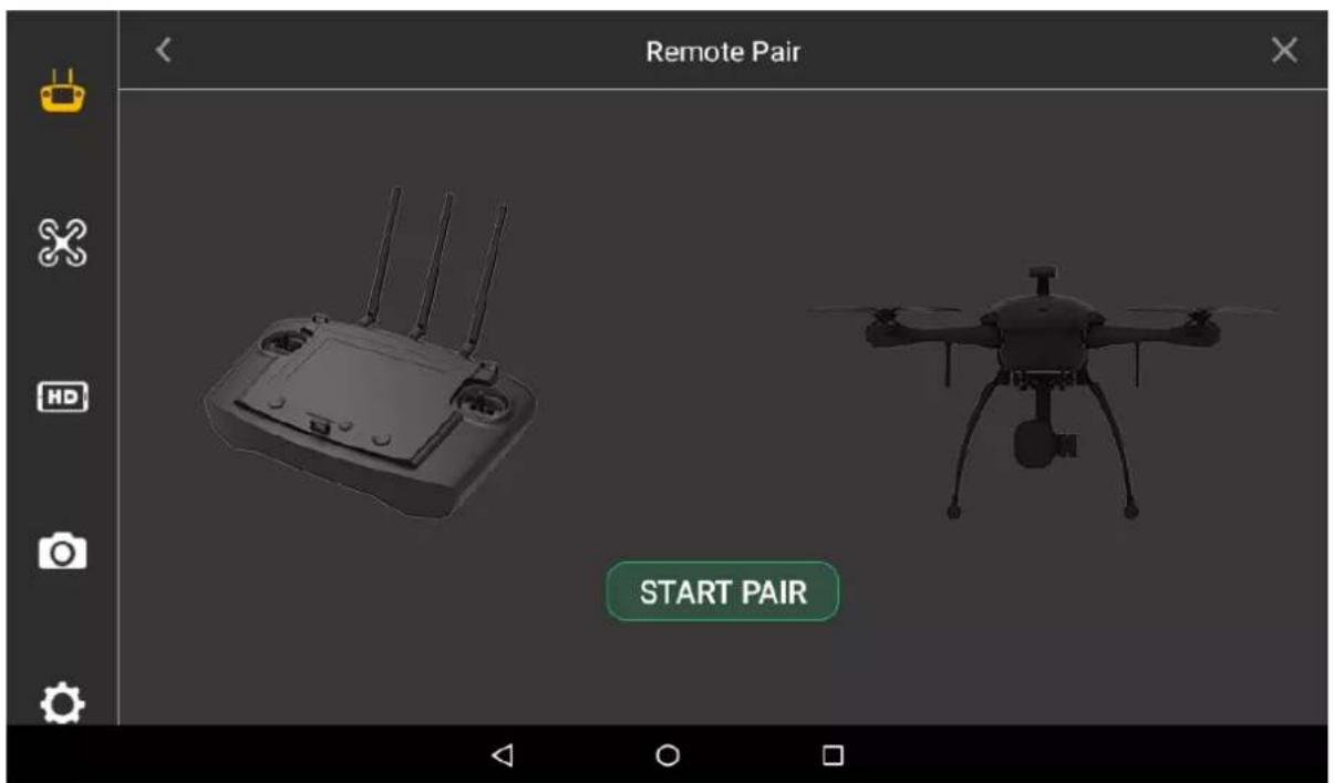
Appendix Figure 3-2
Step 3 Click "Start Pair" on the remote control, and the system starts pairing automatically.
Step 4 It means pairing is successful when the remote control prompts "Success".
Step 5 If the interface prompts pairing failure, click "Retry" and repeat above step 1-4.
Appendix 4.1 FAQ and Solutions of Aircraft
Question: Images are subject to water ripple and jitter in case of gale.
Solution: Prevent PTZ from facing the gale directly.
Appendix 4.2 FAQ and Solutions of Remote Control
Question: Response speed of remote control touch screen becomes slow and has other abnormalities.
Solution: Restart the remote control with power switch at the back of remote control. Please timely contact the supplier if it is not improved.
Appendix 4.3 FAQ and Solutions of Airborne Device
Question: Recorded video loss (including failure to copy data from micro SD card).
Solution: Check the aircraft version. Please contact the supplier if the version is too low.
Appendix 4.4 FAQ and Solutions of Charger
Question: Charger displays error prompts: ERR1 (Starting Connection Error), ERR2 (Current Abnormity Protection), ERR3 (Balance Port Fault), ERR4 (AC Input Fault) and ERR5 (Charging Connection Error).
Solution: Please inspect whether connection between AC power line and charger, or connection between charger and battery is abnormal or not. Please contact the manufacturer if it fails to be solved.

ZHEJIANG DAHUA VISION TECHNOLOGY CO., LTD.
Address: No. 1199, Bin'an Road, Binjiang District, Hangzhou, P.R. China
Postcode: 310053
Tel: +86-571-87688883
Fax: +86-571-87688815
Email: overseas@dahuatech.com
Website: www.dahuasecurity.com
- Trademark
- Update and Modification
- Document Overview
- Applied Model
- Application Object
- Symbol Definition
- Document Material
- Revision Record
- Important Safeguards and Warnings
- Danger
- Warning
- Caution
- Flight Environment
- Power Requirement
- Battery Points of Attention
- ! Caution
- Application Environment Requirements
- Operation and Maintenance Requirements
- Privacy Protection Notice
- About the Manual
- Legal Statement...... I
- Preface....II
- Important Safeguards and Warnings ...... V
- Product Introduction....1
- Structure....3
- Flight Preparation.... 25
- Enable Flight.... 47
- End Flight....73
- Upgrade and Update....77
- Appendix 1 Main Technical Parameters ...... 79
- Appendix 2 Aircraft State Indicator 82
- Appendix 3 System Pairing....84
- Appendix 4 FAQ....86
- Overview
- Functional Features
- Integrated Design
- Folded Packages
- HD Video
- Accurate Positioning
- Wireless Transmission
- Low Electric Quantity Protection
- Intelligent Battery of Aircraft
- Flight Control
- Electronic Fence (e-fence)
- Note
- Aircraft
- Product Dimensions
- Structural Component
- Airborne Device
- The 2MP Visible Light PTZ Camera
- Structural Component
- Remote Control
- Dimensions
- Structural Component
- Table 2-5
- Buttons
- Scroll Wheel
- PTZ Mode Lever
- 2-level lever:
- Shooting
- Operation Interface
- Function Setting and State Bar
- Setting
- Flight State List
- Quick Operation
- State Display Bar
- Preview
- Video Preview Mode
- Map Preview Mode
- General Functions
- Set Home Point
- Locking Mode
- Unpack
- Check Remaining Power
- Aircraft
- Aircraft Battery Check
- Aircraft Remaining Power
- Remote Control
- Remote Control Battery Check
- Remaining Power of Remote Control
- Charging
- Aircraft Battery Charging
- Remote Control Charging
- Prepare Airborne Device
- Demount PTZ Camera
- Install PTZ Camera
- Prepare Aircraft
- Unfold Arm
- Open Antenna
- Tips
- Remove Sheath
- Open Propeller
- Install and Enable Aircraft Battery
- Prepare Remote Control
- Install Micro SD Card
- Open Antenna
- Enable Remote Control Power
- Confirm Remote Control Mode
- Set Quick Operation
- Dashboard
- PTZ
- Image Transfer
- Other
- Fly Task
- Flight Data
- Enable Aircraft Power
- Check and Debugging
- Remote Control Calibration
- Accelerometer Calibration
- Initialization Failure
- Abnormity Prompt
- Possible Reasons
- Solutions
- Geomagnetic Abnormity
- GPS Satellites Insufficiency
- Flight Mode
- Manual Flight Mode
- Introduction to Manual Flight Flow
- Unlock Flight Control
- Manual Takeoff
- Manual Flight Control
- - Mode 2:
- Manual RTH and Landing
- Manual Locking
- Intelligent Mode
- Intelligent Flight Mode
- Waypoints
- Circle
- Intelligent Locking Mode
- Intelligent Operation
- Auto Takeoff
- Auto RTH and Landing
- One-key Landing
- Intelligent Protection Mechanism
- Low Battery
- Out of Control
- Remote Control Setting
- Remote Button User-defined
- Flight Control Settings
- Fence Settings
- Fence Action
- Other Settings
- Enable Electronic Fence
- Preview Settings
- Camera Settings
- Photo Settings
- Video Settings
- Image Settings
- General Settings
- Other Settings
- Network Settings
- Micro SD Settings
- Brightness
- Date and time
- Language
- About
- Turn off Power
- Dismantle Air-borne Device
- Fold Aircraft
- Copy Video of Camera Micro SD Card
- Remove Other Components
- Firmware Update
- Firmware Update
- UPDATE NOW
- Figure 6-1
- Remote Control Update
- APP Update
- APP Update
- 1.2.14
- Figure 6-2
- Download and Update Offline Map of Remote Control
- Abnormity
- Specific Operations
- Appendix 4.1 FAQ and Solutions of Aircraft
- Appendix 4.2 FAQ and Solutions of Remote Control
- Appendix 4.3 FAQ and Solutions of Airborne Device
- Appendix 4.4 FAQ and Solutions of Charger
Brand : Dahua Technology
Model : X650CS
Category : Drone