
OMX-01HMBT0013 - Audio/video converter Ocean Matrix - Free user manual and instructions
Find the device manual for free OMX-01HMBT0013 Ocean Matrix in PDF.


| Product Type | Audio/Video Converter |
| Brand | Ocean Matrix |
| Model | OMX-01HMBT0013 |
| Dimensions (approx.) | 10 x 5 x 2 cm |
| Weight (approx.) | 100 g |
| Power Supply | USB 5V DC (cable included) |
| Input Interface | HDMI |
| Output Interface | HDMI |
| Supported Resolutions | Up to 1080p @60Hz |
| Audio Support | Stereo audio pass-through |
| Plug and Play | Yes, no drivers required |
| LED Indicators | Power and signal status |
| Housing Material | Aluminum alloy |
| Operating Temperature | 0°C to 45°C |
| Storage Temperature | -10°C to 60°C |
| Cleaning Instructions | Wipe with a dry, soft cloth |
| Safety Precautions | Keep away from water and moisture |
| Spare Parts Availability | Not available separately |
| Repairability | Non-repairable, replace unit |
| Package Contents | Converter, USB cable, manual |
Frequently Asked Questions - OMX-01HMBT0013 Ocean Matrix
User questions about OMX-01HMBT0013 Ocean Matrix
0 question about this device. Answer the ones you know or ask your own.
Ask a new question about this device
Download the instructions for your Audio/video converter in PDF format for free! Find your manual OMX-01HMBT0013 - Ocean Matrix and take your electronic device back in hand. On this page are published all the documents necessary for the use of your device. OMX-01HMBT0013 by Ocean Matrix.
USER MANUAL OMX-01HMBT0013 Ocean Matrix
Description:
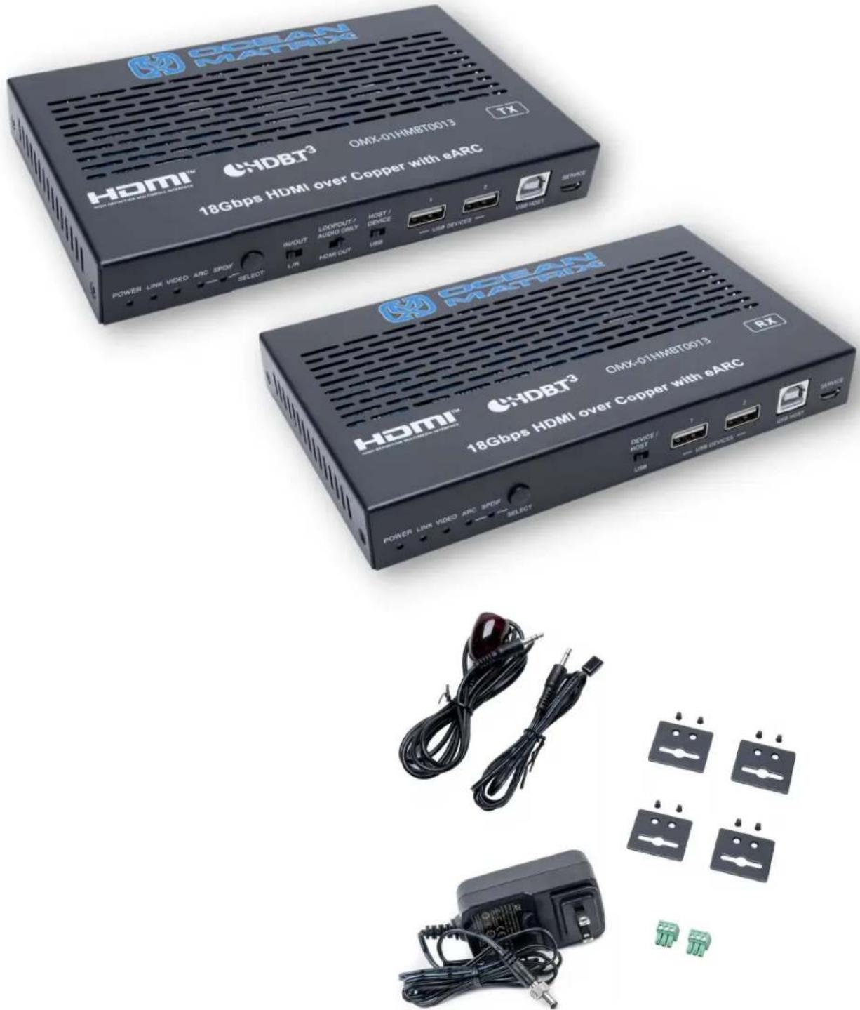
The Ocean Matrix OMX-01HMBT0013 is an HDBaseT 3.0 extender that can send uncompressed HD/UHD video and audio signals, eARC/ARC, RS-232, bi-directional IR, 1GbE ethernet, and USB2.0 signals up to 100m/328ft via a single Cat6a/7 cable. This extender is a convenient solution for extension of HDMI and other signals via a single CAT cable over long distances, making it the perfect solution for most commercial applications.
Features:
• HDMI 2.0b, HDCP 2.2 and HDBaseT 3.0 Compliant
• Uncompressed 4K @ 60HZ 4:4:4 up to 18Gbps Video Bandwidth
• HDR, HRD10, HDR10+, Dolby Vision, and HLG Pass Through
- LPCM, Dolby Digital/Plus/EX, Dolby TrueHD, DTS, DTS-EX, DTS-96/24, DTS High Res, DTS-HD Master Audio, DSD Pass Through
• Transmission Distance up to 328ft (100m via a Single Cat 6a/7 Cable)
• Supports eARC/ARC Function
• Bi-Directional IR, RS-232, and 1G Ethernet Signal Pass Through
• Supports USB2.0 Transmission, Host/Device is Configurable
• Bi-Directional 24V POC Function
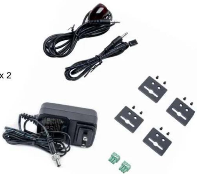
Item Includes:
- IR Blaster Cable
- IR Receiver Cable
- Mounting Ears x 4
• Machine Screws (KM3*4) x 8
• 3PIN-3.81mm Phoenix Connector x 2
• 24V/1A Locking Power Adapter
Specifications:
• HDMI Compliance: HDMI 2.0b
• HDCP Compliance: HDCP 2.2
• Video Bandwidth: 18Gbps
• Video Resolution: Up to 4K @ 60Hz 4:4:4
• Transmission Distance: 328ft / 100m (via Single Cat 6a/7C Cable)
- HDBaseT Bandwidth 16Gbps on Main and 2Gbps on Return Link
• HDR: HDR, HDR10, HDR10+, Dolby Vision, HLG
• Color Space: RGB, YCbCr 4:4:4, YCbCr 4:2:2, YCbCr 4:2:0
• Color Depth: 8/10/12-bit
- Audio Formats: LPCM, Dolby Digital/Plus/EX, Dolby TrueHD, DTS, DTS-EX, DTS-96/94, DTS High Res, DTS-HD Master Audio, DSD
• L/R Audio Formats: PCM 2.0
• SPDIF Audio Formats: LPCM 2.0, AC3 5.1, DTS 5.1
- IR Level: 12Vp-p
• IR Bandwidth: 20K-60KHz
• USB Bandwidth: Up to 350Mbps
- Ethernet: 1000Mbps
• RS-232: Up to 921600bps
• TX Inputs: 1 x HDMI In (Type A, 19-Pin Female)
- TX Outputs: 1 x HDMI Out (Type A, 19-Pin Female), 1 x HDBaseT Out (RJ45, 8-Pin Female), 1 x SPDIF Out (S/PDIF), 1 x L/R Out (3.5mm Stereo Mini-Jack)
- TX Controls: 1 x IR In (3.5mm Stereo Mini-Jack), 1 x IR Out (3.5mm Stereo Mini-Jack), 1 x RS-232 (3-Pin-3.81 Phoenix Jack), 1 x Service (Mini-USB, Update Port), 1 x USB Host (USB Type B), 2 x USB Devices (USB Type A), 1 x LAN (RJ45)
- RX Inputs: 1 x HDBaseT In (RJ45, 8-Pin Female), 1 x SPDIF In (S/PDIF)
• RX Outputs: 1 x HDMI Out (Type A, 19-Pin Female), 1 x L/R Out (3.5mm Stereo Mini-Jack)
- Controls: 1 x IR In (3.5mm Stereo Mini-Jack), 1 x IR Out (3.5mm Stereo Mini-Jack), 1 x RS-232 (3-Pin- 3.81 Phoenix Jack), 1 x Service (Mini-USB, Update Port), 1 x USB Host (USB Type B), 2 x USB Devices (USB Type A), 1 x LAN (RJ45)
• Dimensions (LxWxH): TX/RX 6.69 x 4.04 x 0.89in (170 x 102 x 22mm)
• Weight: TX: 0.98lbs (425g) / RX: 0.96lbs (437g)
- Power Supply: Input: AC 100-240V 50/60Hz / Output: DC 24V/1A (US/EU Standard, CE/FCC/UL Certified)
• Power Consumption: 15.36W (POC)
• Operating Temperature: 32 - 104°F (0 - 40°C)
• Storage Temperature: -4 - 140°F (-20 - 60°C)
• Relative Humidity: 20 - 90% RH (No Condensation)
Operation Controls and Functions: Transmitter:
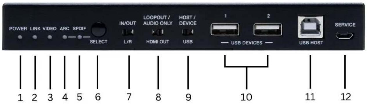

- Power LED Indicator - Red light indicates that the TX is powered on
- Link LED - Light on: TX and RX are in good connection status. Light Flashing: TX and RX are in low power mode. Light Off: TX and RX are not connected.
- Video LED - Light on: The video is encrypted. Light flashing: the video is not encrypted. Light Off: no HDMI input.
- ARC LED - Light on: The device is switched to the ARC mode. Light off: the device is switched to the SPDIF mode.
- SPDIF LED - Light on: The device is switch to SPDIF mode. Light off: the device is switched to ARC mode.
- Select Button- Used for switching the ARC mode and the SPDIF mode.
- L/R IN/OUT Switch - Switch to the left (loopout), the HDMI out port is the loopout port for the HDMI in port.
- Loopout/Audio Only Switch - Switch to the left (loopout), the HDMI out port is the loopout port for the HDMI in port; switch to the right (audio only) the HDMI out port outputs 720p black screen image, and the audio is from ARC or SPDIF.
- Host/Device USB Switch - Switch to the left (host), the USB host mode is enabled; switch to the right (device), the USB device is enabled.
- USB Devices - Two USB device ports. connected to UDISK, mouse or keyboard.
- USB Host - USB extension host port, connected to PC.
- Service - For factory use only.
- DC 24V - DC 24V/1A power supply input port.
- LAN - 1G network port.
- HBDT Out - 10G network port, connected to the HDBT in port of receiver with a CAT6a/7 cable. It is used for various signals pass-through.
- HDMI In - HDMI signal input port, connected to signal source device, supporting EARC/ARC amplifier.
- HDMI Out - HDMI signal loopout port. It can choose to be a loopout or audio only port through the loopout/audio only switch.
- L/R/In/Out - Audio embedding / de-embedding port. It can be used for audio embedding/de-embedding through the L/R in/out switch.
- SPDIF Out - Optical output port.
Operation Controls and Functions: Receiver:

- Power LED Indicator - Red light indicates that the TX is powered on
- Link LED - Light on: TX and RX are in good connection status. Light Flashing: TX and RX are in low power mode. Light Off: TX and RX are not connected.
- Video LED - Light on: The video is encrypted. Light flashing: the video is not encrypted. Light Off: no HDMI input.
- ARC LED - Light on: The device is switched to the ARC mode. Light off: the device is switched to the SPDIF mode.
- SPDIF LED - Light on: The device is switch to SPDIF mode. Light off: the device is switched to ARC mode.
- Select Button- Used for switching the ARC mode and the SPDIF mode.
- Host/Device USB Switch - Switch to the left (host), the USB host mode is enables; switch to the right (device), the USB device is enabled.
- USB Devices - Two USB device ports. connected to UDISK, mouse or keyboard.
- USB Host - USB extension host port, connected to PC.
- Service - For factory use only.
- DC 24V - DC 24V/1A power supply input port.
- LAN - 1G network port.
- HBDT In- 10G network port, connected to the HDBT out port of transmitter with a CAT6a/7 cable. It is used for various signals pass-through.
- HDMI Out - HDMI signal output port. It can choose to be a loopout or audio only port through the loopout/audio only switch.
- L/R/In/Out - Audio de-embedding output port.
- SPDIF In- Optical input port.
- IR IN - IR signal input port, connected to the IR receiver cable.
- IR Out - IR signal output port, connected to IR blaster cable.
19.RS-232 - RS-232 serial port, used for serial port command transmission.
Connection Instructions:
1) Connect the source to the transmitter
2) Connect the display to the receiver
3) Connect a CAT6a/7 cable between the units
4) Connect the included power supply to either the transmitter or the receiver.
Input and Output Switching:
The Ocean Matrix OMX-01HMBT0013 can switch to ARC/SPDIF mode by pressing the SELECT button on the front panel of both the transmitter and receiver. The HDMI OUT port of the transmitter can turn to LOOP OUT or AUDIO ONLY through the LOOP OUT/AUDIO ONLY switch. The input and output routing are different for different scenarios, as shown in the diagrams below:
1) Set the Extender to SPDIF Mode. Then switch the LOOP OUT/AUDIO ONLY switch to right, the HDMI OUT port of the transmitter is set to AUDIO ONLY.
![graph LR A["DVD"] -->|HDMI IN ARC AUDIO ONLY| B["TX"] C["Audio Amplifier"] -->|SPDIF OUT| B D["Speakers"] -->|SPDIF OUT| B B -->|UTP Cable| E["RX"] E -->|HDMI OUT| F["TV"] E -->|SPDIF IN| F](/content/2026/05/1084103/images/21ea7e1f5086655f6fbc023c437d212782d41575cd27284d4172ac4beecdd895.jpg)
2) Set the Extender to SPDIF Mode. Then switch the LOOP OUT/AUDIO ONLY switch to left, the HDMI OUT port of the transmitter is set to LOOP OUT.
![graph LR A["TV"] -->|HDMI IN ARC LOOP OUT| B["TX"] B -->|UTP Cable| C["RX"] C -->|HDMI OUT| D["TV"] B -->|SPDIF OUT| E["Audio Amplifier"] E --> A](/content/2026/05/1084103/images/443e9f83a74e8032385e7b75e30a9191741a8ba143cd14ce0a3f81529802cb36.jpg)
3) Set the Extender to ARC Mode. Then switch the LOOP OUT/AUDIO ONLY switch to right, the HDMI OUT port of the transmitter is set to AUDIO ONLY.
![graph LR A["Soundbar with ARC"] -->|HDMI IN ARC AUDIO ONLY| B["TX"] C["Audio Amplifier"] -->|SPDIF OUT| B D["Speakers"] -->|SpdIF OUT| B B -->|UTP Cable| E["RX"] E -->|HDMI OUT ARC| F["TV with ARC"]](/content/2026/05/1084103/images/f0af487022c951ca540292ef7c5b4e95b00f77465e29232efd991c8a9639b020.jpg)
Input and Output Switching:
4) Set the Extender to ARC Mode. Then switch the LOOP OUT/AUDIO ONLY switch to left, the HDMI OUT port of the transmitter is set to LOOP OUT.
![graph LR A["Soundbar with ARC"] -->|HDMI IN ARC| B["TX"] B -->|UTP Cable| C["RX"] C -->|HDMI OUT ARC| D["TV with ARC"] E["Audio Amplifier"] -->|SPDIF OUT| B](/content/2026/05/1084103/images/dee9d60c39653a6bbddb08e9de8bab3379529b0fa59bc5bed9af0fd919ac9d1d.jpg)
5) Set the Extender to eARC Mode. Then switch the LOOP OUT/AUDIO ONLY switch to right, the HDMI OUT port of the transmitter is set to AUDIO ONLY.
![graph LR A["Soundbar with eARC"] -->|HDMI IN eARC| B["TX"] C["Audio Amplifier"] -->|AUDIO ONLY| B D["Speakers"] -->|SPDIF OUT ≤ 5.1CH| B B -->|UTP Cable| E["RX"] E -->|HDMI OUT eARC| F["TV with eARC"]](/content/2026/05/1084103/images/d4c1167a6f530061a4bf51dfcf97586a813cf432fd2dee60cc63aeb33df6249f.jpg)
6) Set the Extender to eARC Mode. Then switch the LOOP OUT/AUDIO ONLY switch to left, the HDMI OUT port of the transmitter is set to LOOP OUT.
![graph LR A["Soundbar with eARC"] -->|HDMI IN eARC| B["TX"] B -->|UTP Cable| C["RX"] C -->|HDMI OUT eARC| D["TV with eARC"] E["Audio Amplifier"] -->|SPDIF OUT ≤ 5.1CH| B](/content/2026/05/1084103/images/98f0b6441a3abc0a4d0ca499fd5a1f4f9717f67ab12ebca5314e4c8b5e44e251.jpg)
Audio Embedding and De-embedding:
The Transmitter supports audio embedding and de-embedding. The L/R IN/OUT port can be used for audio embedding or de-embedding through the L/R IN/OUT switch.
• TX Audio Embedding:
When the L/R IN/OUT switch is switched to left, the audio from external audio devices will be embedded to the L/R IN/OUT port.
![graph LR A["MP3 Player"] -->|L/R IN| B["TX"] C["DVD"] -->|HDMI IN| B B -->|UTP Cable| D["RX"] D -->|HDMI OUT| E["TV"]](/content/2026/05/1084103/images/8f14ee5203f4566c03a62d2b0854574081358169519e52ac9fd9fdf68022b73f.jpg)
• TX Audio De-embedding:
When the L/R IN/OUT switch is switched to right, The L/R IN/OUT port will output the audio de-embedded from the HDMI IN port.
![graph LR A[" DVD "] -->|HDMI IN| B["TX"] C[" Audio Amplifier "] -->|L/R OUT| B B -->|UTP Cable| D["RX"] D -->|HDMI OUT| E["TV"]](/content/2026/05/1084103/images/8b3fd2434c283874380aa0ea050f0cc667efe1dfda99a8bc5077eec74b37517f.jpg)
USB Mode Applications:
The Extender supports USB 2.0 transmission, and Host/Device is configurable.
• Mode 1: USB forward from TX to RX
Switch the HOST/DEVICE USB switch to left, then power off and reboot the transmitter to set to USB Host mode. Meanwhile, switch the DEVICE/HOST USB switch to left, then power off and reboot the receiver to set to USB Device mode.
![graph LR A["Computer Host"] -->|HDMI IN USB Host LOOPOUT| B["TX"] C["Local Monitor"] -->|USB Devices| B D["Keyboard & Mouse"] -->|USB Devices| B B -->|UTP Cable| E["RX"] E -->|USB Device| F["Remote Monitor"] E -->|USB Host| G["No Function"] E -->|USB Device| H["Keyboard & Mouse"] style A fill:#f9f,s…](/content/2026/05/1084103/images/ef30437a12cb9708367560260c64671ea4a58fa8f6be10e6cee1802b39b37f80.jpg)
• Mode 2: USB forward from RX to TX
Switch the HOST/DEVICE USB switch to right, then power off and reboot the transmitter to set to USB Device mode. Meanwhile, switch the DEVICE/HOST USB switch to right, then power off and reboot the receiver to set to USB Host mode.
![graph LR A["NoteBook"] -->|No Function| B["Local Monitor"] B -->|USB Devices| C["TX"] C -->|UTP Cable| D["RX"] D -->|USB Host| E["Computer Host"] D -->|USB Devices| F["Remote Monitor"] F --> G["Keyboard & Mouse"] C -->|HDMI IN USB Host LOOPOUT| B B -->|USB Devices| H["Keyboard & Mouse"]](/content/2026/05/1084103/images/86e5f18ee831745a0989a44e793637c87cd682dbf60471f68b43c3b30eb2b1cc.jpg)
IR Pin Definition:
IR Receiver and Blaster pin configuration is as follows:


Note: When the angle between the IR receiver and the remote control is ±45° , the transmission distance is 0-5 meters; when the angle between the IR receiver and the remote control is ±90° , the transmission distance is 0-8 meters.
Application Example Diagram

PRODUCT SERVICE
Damage requiring service:
- The unit should be serviced by qualified service personnel if:
• (a) The DC power supply cord or AC adaptor has been damaged
• (b) Objects or liquids have gotten into the unit
• (c) The unit has been exposed to rain
(d) The unit does not operate normally or exhibits a marked change in performance; The unit has been dropped or the cabinet is damaged.
• (2) Servicing Personnel: Do not attempt to service the unit beyond that described in these operating instructions. Refer all other servicing to authorized servicing personnel.
• (3) Replacement parts: When parts need replacing ensure the servicer uses parts specified by the manufacturer. Unauthorized substitutes may result in fire, electric shock, or other hazards.
• (4) Safety check: After repairs or service, ask the servicer to perform safety checks to confirm that the unit is in proper working condition.
SAFETY PRECAUTIONS
Please read all instructions before attempting to unpack, install or operate this equipment and before connecting the power supply.
Please keep the following in mind as you unpack and install the unit:
- Always follow basic safety precautions to reduce the risk of fire, electrical shock and injury to persons.
- To prevent fire or shock hazard, do not expose the unit to rain, moisture or install this product near water.
- Never spill liquid of any kind on or into this product.
- Never push an object of any kind into this product through any openings or empty slots in the unit, as you may damage parts inside the unit.
- Do not attach the power supply cabling to building surfaces.
- Use only the supplied power supply unit (PSU). Do not use the PSU if it is damaged.
- Do not allow anything to rest on the power cabling or allow any weight to be placed upon it or any person walk on it.
- To protect the unit from overheating, do not block any vents or openings in the unit housing that provide ventilation and allow for sufficient space for air to circulate around the unit
WARRANTY
1 Year
- DESCRIPTION
- FEATURES
- ITEM INCLUDES
- SPECIFICATIONS
- OPERATION CONTROLS AND FUNCTIONS: TRANSMITTER
- OPERATION CONTROLS AND FUNCTIONS: RECEIVER
- CONNECTION INSTRUCTIONS
- INPUT AND OUTPUT SWITCHING
- AUDIO EMBEDDING AND DE-EMBEDDING
- TX AUDIO EMBEDDING
- TX AUDIO DE-EMBEDDING
- USB MODE APPLICATIONS
- MODE 1: USB FORWARD FROM TX TO RX
- MODE 2: USB FORWARD FROM RX TO TX
- IR PIN DEFINITION
- PRODUCT SERVICE
- DAMAGE REQUIRING SERVICE
- SAFETY PRECAUTIONS
- WARRANTY
Brand : Ocean Matrix
Model : OMX-01HMBT0013
Category : Audio/video converter